EP3099614B1 - Verlegearm für eine vorrichtung zum wickeln eines strangförmigen wickelguts - Google Patents
Verlegearm für eine vorrichtung zum wickeln eines strangförmigen wickelguts Download PDFInfo
- Publication number
- EP3099614B1 EP3099614B1 EP15701478.8A EP15701478A EP3099614B1 EP 3099614 B1 EP3099614 B1 EP 3099614B1 EP 15701478 A EP15701478 A EP 15701478A EP 3099614 B1 EP3099614 B1 EP 3099614B1
- Authority
- EP
- European Patent Office
- Prior art keywords
- winding
- laying arm
- laying
- winding drum
- arm
- Prior art date
- Legal status (The legal status is an assumption and is not a legal conclusion. Google has not performed a legal analysis and makes no representation as to the accuracy of the status listed.)
- Active
Links
- 238000004804 winding Methods 0.000 title claims description 644
- 239000000463 material Substances 0.000 title claims description 123
- 230000033001 locomotion Effects 0.000 claims description 92
- 238000012546 transfer Methods 0.000 claims description 10
- 230000007246 mechanism Effects 0.000 claims description 5
- 238000006073 displacement reaction Methods 0.000 description 40
- 239000004033 plastic Substances 0.000 description 38
- 238000000034 method Methods 0.000 description 24
- 230000001105 regulatory effect Effects 0.000 description 21
- 230000008859 change Effects 0.000 description 17
- 238000005096 rolling process Methods 0.000 description 17
- 238000011161 development Methods 0.000 description 15
- 230000008569 process Effects 0.000 description 14
- 230000005540 biological transmission Effects 0.000 description 13
- 230000007935 neutral effect Effects 0.000 description 6
- 230000033228 biological regulation Effects 0.000 description 5
- 239000003000 extruded plastic Substances 0.000 description 5
- 238000001125 extrusion Methods 0.000 description 5
- 238000004519 manufacturing process Methods 0.000 description 5
- 230000001960 triggered effect Effects 0.000 description 5
- 230000008878 coupling Effects 0.000 description 4
- 238000010168 coupling process Methods 0.000 description 4
- 238000005859 coupling reaction Methods 0.000 description 4
- 238000013016 damping Methods 0.000 description 4
- 230000007423 decrease Effects 0.000 description 4
- 238000010276 construction Methods 0.000 description 3
- 238000012937 correction Methods 0.000 description 3
- 238000010586 diagram Methods 0.000 description 3
- 238000005516 engineering process Methods 0.000 description 3
- OKTJSMMVPCPJKN-UHFFFAOYSA-N Carbon Chemical group [C] OKTJSMMVPCPJKN-UHFFFAOYSA-N 0.000 description 2
- 239000004952 Polyamide Substances 0.000 description 2
- 239000007853 buffer solution Substances 0.000 description 2
- 238000001816 cooling Methods 0.000 description 2
- 238000001514 detection method Methods 0.000 description 2
- 238000009434 installation Methods 0.000 description 2
- 230000000737 periodic effect Effects 0.000 description 2
- 229920002647 polyamide Polymers 0.000 description 2
- 230000000284 resting effect Effects 0.000 description 2
- 239000002023 wood Substances 0.000 description 2
- 238000013459 approach Methods 0.000 description 1
- 230000015572 biosynthetic process Effects 0.000 description 1
- 239000000872 buffer Substances 0.000 description 1
- 238000006243 chemical reaction Methods 0.000 description 1
- 210000000078 claw Anatomy 0.000 description 1
- 238000004891 communication Methods 0.000 description 1
- 230000000295 complement effect Effects 0.000 description 1
- 230000003111 delayed effect Effects 0.000 description 1
- 230000001419 dependent effect Effects 0.000 description 1
- 230000001066 destructive effect Effects 0.000 description 1
- 230000005284 excitation Effects 0.000 description 1
- 239000000835 fiber Substances 0.000 description 1
- 229910021389 graphene Inorganic materials 0.000 description 1
- 230000005484 gravity Effects 0.000 description 1
- 238000003780 insertion Methods 0.000 description 1
- 230000037431 insertion Effects 0.000 description 1
- 238000003032 molecular docking Methods 0.000 description 1
- 238000012544 monitoring process Methods 0.000 description 1
- 210000000056 organ Anatomy 0.000 description 1
- 230000002093 peripheral effect Effects 0.000 description 1
- 230000036316 preload Effects 0.000 description 1
- 238000004886 process control Methods 0.000 description 1
- 238000012545 processing Methods 0.000 description 1
- 230000002035 prolonged effect Effects 0.000 description 1
- 238000000926 separation method Methods 0.000 description 1
- 230000008054 signal transmission Effects 0.000 description 1
- 238000009751 slip forming Methods 0.000 description 1
- 239000007787 solid Substances 0.000 description 1
- 238000003860 storage Methods 0.000 description 1
- 238000013519 translation Methods 0.000 description 1
- XLYOFNOQVPJJNP-UHFFFAOYSA-N water Substances O XLYOFNOQVPJJNP-UHFFFAOYSA-N 0.000 description 1
- 210000003857 wrist joint Anatomy 0.000 description 1
Images


Classifications
-
- B—PERFORMING OPERATIONS; TRANSPORTING
- B65—CONVEYING; PACKING; STORING; HANDLING THIN OR FILAMENTARY MATERIAL
- B65H—HANDLING THIN OR FILAMENTARY MATERIAL, e.g. SHEETS, WEBS, CABLES
- B65H54/00—Winding, coiling, or depositing filamentary material
- B65H54/02—Winding and traversing material on to reels, bobbins, tubes, or like package cores or formers
- B65H54/28—Traversing devices; Package-shaping arrangements
- B65H54/2848—Arrangements for aligned winding
- B65H54/2851—Arrangements for aligned winding by pressing the material being wound against the drum, flange or already wound material, e.g. by fingers or rollers; guides moved by the already wound material
-
- B—PERFORMING OPERATIONS; TRANSPORTING
- B65—CONVEYING; PACKING; STORING; HANDLING THIN OR FILAMENTARY MATERIAL
- B65H—HANDLING THIN OR FILAMENTARY MATERIAL, e.g. SHEETS, WEBS, CABLES
- B65H54/00—Winding, coiling, or depositing filamentary material
- B65H54/02—Winding and traversing material on to reels, bobbins, tubes, or like package cores or formers
- B65H54/28—Traversing devices; Package-shaping arrangements
- B65H54/2848—Arrangements for aligned winding
- B65H54/2854—Detection or control of aligned winding or reversal
- B65H54/2857—Reversal control
- B65H54/286—Reversal control by detection that the material has reached the flange or the reel end
-
- B—PERFORMING OPERATIONS; TRANSPORTING
- B65—CONVEYING; PACKING; STORING; HANDLING THIN OR FILAMENTARY MATERIAL
- B65H—HANDLING THIN OR FILAMENTARY MATERIAL, e.g. SHEETS, WEBS, CABLES
- B65H2701/00—Handled material; Storage means
- B65H2701/30—Handled filamentary material
- B65H2701/33—Hollow or hose-like material
- B65H2701/331—Hollow or hose-like material leaving an extruder
Definitions
- the invention relates to a laying arm for a device for winding winding a strand-shaped winding material, such as a continuously extruded tube, preferably made of plastic on a rotating winding drum.
- a strand-shaped winding material such as a continuously extruded tube, preferably made of plastic on a rotating winding drum.
- the winding material such as an extruded plastic pipe, such as a cable duct, in which a fiber optic cable can be installed protected, it is inter alia important to keep the winding material in a length of several hundred meters in a limited building site in stock, in particular underground to move long distances.
- the take-up operation directly adjoins the production process, in particular the extrusion, of the winding material, so that the just-extruded plastic material to be wound leaves a cooling station without being cut and is fed to the winding device.
- the winding process itself is then usually controlled by an operator and optionally manipulated manually.
- a standard winding drum made of wood When using a cable protection tube as a winding material usually a standard winding drum made of wood is used. The cable protection tube wrapped on the wooden winding drum is delivered to construction sites to install it as needed.
- Such cheap, standardized wooden winding drums or other winding drums have proven themselves due to a relatively low price and the possible reusability especially in use on construction sites.
- the winding drums have rotationally asymmetric axial and radial impacts due to imbalances on the lateral side flanges and on the drum core. Because of the geometric irregularity of the winding drum is a constantly supervised by an operator according to the prior art and manipulated winding of the winding material necessary.
- Winding methods and winding devices are known per se in automation technology, in which electric cables are wound onto geometry-precise rollers.
- EP 0203046 B1 discloses, for example, a cable winder in which a guide arm, which is directed to the winding roll, a plurality of arm members, which are interconnected by means of a plurality of wrist joints.
- a cable winder in which a guide arm, which is directed to the winding roll, a plurality of arm members, which are interconnected by means of a plurality of wrist joints.
- Straight wire winders are products of high material quality and uniform and constant material properties. For such windings, a higher cost is operated to provide ideal geometric, unbalance winding coils.
- the known automated winding techniques can not be used successfully when a winding material and a winding drum are used whose material or geometry properties are unpredictable.
- EP 0 147 619 A2 shows a guide device for a cable conveyor for unwinding a cable on a limited by flanges and rotationally driven cable drum.
- a traverse unit moves a transfer arm between the flanges to wind the cable over the drum width.
- the laying arm has, at its drum-side end, in each case a contact area facing the respective side wall flange, with which the laying arm comes into contact with the respective flange when the end position is reached.
- US 3,951,355 A discloses an automatic cable winding device in which a cable is wound by means of a traversing on a rotatably driven drum, wherein a Traversierarm is moved oscillating parallel to the axis of rotation of the drum via a Traversierbett and signaled by reaching the end positions proximity switches the achievement of the respective Sowandflanschs.
- the laying arm may preferably be carried and placed by an actuating device, such as a robot, preferably in accordance with a control and / or regulating routine.
- the laying arm serves to channelize the stranded or wound material to the winding drum and to transfer it for winding, while the laying arm is moved back and forth, in particular substantially transversely to its longitudinal extent and linearly between the axial ends, such as the side wall flanges ,
- the laying arm follows in particular stepwise the axial winding progress of the wound on the winding drum winding material.
- the laying arm has a winding drum-side end which is in a contact, in particular rolling contact, with the winding drum or the winding layer already wound thereon for a large part of the entire winding process and on which a contact region facing the respective side flange of the winding drum is formed the laying arm comes into abutting contact with one of the two side flanges, in particular when a turning operation is carried out.
- the contact can be formed as 6.3schleif- or rolling contact.
- the device according to the invention has a displacement sensor arranged at the winding end, such as a contactor which emits a control signal, such as a turning operation trigger signal, at least when reaching at least one predefined winding position, at least one triggering position for the turning operation.
- the control signal is sent to an electronic control and / or regulating device, whereby a control for changing a specific control variable of the winding method can be triggered.
- the control and / or regulating device performs a turning operation in which the old winding position is completed and the new winding position on the old winding position is started. In the turning operation, a change of direction of the laying movement of the laying arm is accompanied.
- the displacement sensor in the region of each abutment region has an actuating projection which protrudes in an unactuated position from the respective abutment region in forward or Herverlegeschulsraum and preferably such movable, in particular pivotally mounted on the laying arm, that the respective actuating projection in its release position the respective contact area for the contact with the side wall flange releases.
- the inventors have found that for the winding technology difficult turning or wall operation, the placement of the winding drum-side end and thus of the laying arm relative to the winding drum is essential in order to realize higher winding speeds of more than 80 m / min can.
- the timing at which distance to the side wall flange of the winding drum and when the turning operation is triggered and terminated is important to realize a faultless completion of the spiral or winding layer and rebuild a solid winding layer base.
- the contactor with its actuating projection projecting in the direction of displacement movement, realizes triggering of the control signal prior to reaching the laying movement limiting outer position of the laying arm achieved when the winding drum end of the laying arm contacts the sidewall flange of the winding drum stands.
- the yielding, in particular rotatable actuating projection allows the contact of the winding drum-side end with the 9.wandflansch to.
- the relevant actuating projection in its release position, is recessed in a vertical view into the laying arm, in particular in a housing structure of the laying arm.
- the laying arm may comprise a transport space limited in particular by plates, preferably completely closed, in which a pivot axis of the actuating projection is arranged, and the respective actuating projection has disappeared on reaching the side flange wall.
- an actuating outer side of the actuating projection comes into sliding contact with the soflanschwand, wherein in particular the operating outer side of the respective actuating projection is substantially flat and planar.
- the actuation outer side of the respective actuation projection is contour-adapted to an outer surface of the abutment region, so that in the release position the actuation outer side lies substantially free of excitation substantially in the plane of the outer surface of the particularly planar abutment region.
- the actuating projection in its unactuated position is at least halfway or around a whole winding material thickness and at most around two winding material thicknesses of the respective contact surface in forward or Herverleeschulsraum.
- an optimized, preliminary triggering of the control signal can be achieved before the contact area of the laying arm comes into contact with the side wall flange. It is clear that the period and / or the winding path between triggering of the control signal and contacting the contact area can be adjusted by triggering the control signal only after exceeding it an adjustable amplitude of movement of the actuating projection is changed from its unactuated position.
- the laying arm has a Wickelgutabgabeö réelle at its winding drum-side end at which the winding material leaves the transport space of the laying arm, to be transferred then in particular guide or contactless of the winding drum.
- the displacement sensor on the laying arm is arranged closer to a substantially cylindrical drum core of the winding drum than the winding material output at which the winding material leaves the laying arm without guidance, under the exclusive influence of gravity and the internal winding force of the winding material.
- the displacement sensor is arranged in the vertical direction below the winding material delivery, wherein in particular the winding material extends without contact on the components of the displacement sensor over to the winding drum.
- the laying arm according to the invention comprises a sword-shaped housing, which is preferably formed of two mutually parallel, extending in the longitudinal direction of the laying arm housing plates delimiting a transport space of the laying arm extending from an actuator-side base portion to the winding drum end of the Laying arms extends.
- the winding material is passed through the transport space extending in the longitudinal direction completely through the laying arm until it reaches a winding material discharge opening.
- the housing plates in particular have an outer surface, which preferably lies in a vertical plane.
- the abutment portion where the winding drum-side end comes into abutting contact with the side wall flange of the winding drum is formed at an axial end portion of the outer surface of the respective housing plate.
- the contact area can be formed by a particular demountable wear plate, in particular of a material of lower friction, such as polyamide.
- the wear plate is preferably arranged interchangeably at the axial end portion of the two housing plates, in particular screwed.
- the contactor has a relative to the laying arm fixedly mounted pivot axis.
- the pivot axis is rotatably mounted on the housing of the laying arm in the interior of the transport space.
- the pivot axis remains stationary in each operating position of the actuating projection within the transport space of the laying arm.
- the pivot axis preferably extends substantially in the vertical direction, so that the respective actuating projection of the contactor is pivoted substantially in a horizontal plane.
- an additional rotary motion sensor accesses the pivot axis of the contactor, so that in particular after exceeding a predetermined pivoting amplitude of the respective actuating projection, the control signal can be generated and delivered.
- a pivoting movement transmission mechanism is housed, in particular within the transport space of the laying arm.
- the swing motion transmission mechanism serves to transmit the pivotal movement of the contactor away from the winding drum end to the base end of the laying arm, preferably without the transmission of motion being realized by conversion to an electronic signal.
- an electrical signal generator can be arranged, which is preferably disposed within or optionally outside the transport space of the laying arm, and generates and forwards the control signal based on the transmitted pivoting movement.
- the pivotal movement transmission mechanism is realized by an angular gear which transmits the pivoting movement of the substantially vertically extending operating projection-side pivot axis of the contactor to a transmission shaft extending in the longitudinal direction (horizontal direction) of the laying arm.
- the actuating projection-side, in particular substantially vertically extending pivot axis of the contactor is biased such, in particular spring-biased that the actuating projection is always forced by its respective release position in the unactuated neutral position.
- the transmission shaft is at least two parts, so that a shaft axis side shaft portion of a pivot axis remote shaft portion is non-destructive disassembled. The division is used for the modular replacement of the entire winding drum-side end of the laying arm to adapt the latter to different strong winding goods can.
- the contactor has a closed ring structure forming a bow shape.
- the bracket is realized axially symmetrically. In the unactuated position of the contactor coincides with the symmetry axis of the ring structure the longitudinal direction of the laying arm together.
- the two actuating projections are part of the bow-shaped triangular structure.
- the triangular structure is preferably realized isosceles, wherein a respective corner of the corner of the triangular bracket shape is rounded off the respective actuating projection.
- the same legs are arranged at an angle of less than 35 ° to each other, preferably about 30 °.
- article of invention is a laying arm for a device for winding winding a strand-shaped winding material, such as a continuously extruded tube, preferably made of plastic on a rotary driven winding drum.
- the laying arm which is part of the winding device, can be provided by an actuating device, such as a robot, in order to transfer the winding material to the winding drum in the case of a particularly substantially linear reciprocating movement.
- the laying arm has a remote from the winding drum arm base, which may be attached to a support of the winding device in particular pivotally mounted in a vertical plane.
- a rail-slide arrangement may be provided for linearly guiding the carrier relative to the actuating device.
- the arm base may in particular be pivotably articulated to the carrier in a vertical plane.
- the laying arm extends from the arm base along an elongated structure constituting the arm shape to an end of the laying arm facing the winding drum.
- the winding drum-side end carries a winding material delivery, which determines a predetermined discharge direction of the winding material away from the laying arm.
- the Wickelgutabgabe may be designed winding specific and therefore suitable only for a certain winding material size.
- the winding drum-side end is coupled to the supporting structure via a mechanical mounting interface which is suitable for detachably detaching or fastening the winding drum-side end from the supporting structure.
- screws are provided, over which the winding drum-side end is releasably secured to the support arm.
- Other alternative fasteners may also be used to ensure interchangeable docking of the winding drum end to the structure.
- winding drum-side end preferably carries all winding material-specific functional components, such as the displacement sensor, which will be explained later, the winding material delivery, a Abrollrad and the like.
- the mechanical mounting interface is realized without electrical connection.
- the mounting interface has only mechanical coupling components, wherein winding operation information, which mainly arise at the winding drum end during winding, are only mechanically detected at the winding drum end and transferred via the mounting interface in the supporting structure of the laying arm.
- winding operation information which mainly arise at the winding drum end during winding
- the structure may be provided for processing a variety of different sized winding goods with corresponding guide elements that can guide several different winding material sizes between the arm base and the winding material delivery of the laying arm through the transport space of the laying arm.
- the structure preferably has a plurality of guide wheels that can accommodate a winding material with a diameter between 5 mm and 50 mm.
- a displacement sensor such as a contactor, arranged at least one predefined position of the winding drum end relative to the winding drum a particular kinematic control signal, such as a turning operation trigger signal, preferably by means of a predetermined movement, in particular pivotal movement , emits a releasably mounted on the winding drum end end release part and mechanically transmits over the mounting interface in the structure.
- a control signal is triggered and transmitted, For example, it can be converted into an electrical signal, ie beyond the exchangeable winding drum-side end, and supplied to a control and / or regulating device, which controls the actuating device such that a turning operation is carried out.
- the displacement sensor is preferably dimensioned in a manner specific to the winding material, wherein a different triggering movement amplitude of the triggering part is preferably set depending on the winding material thickness in order to initiate and deliver the kinematic control signal. The larger the winding material thickness, the greater the triggering movement amplitude.
- the triggering part is mounted for a pivoting movement about a particular vertical bearing arm fixed bearing arm.
- the mounting interface comprises a releasably coupled to the trigger part coupling, such as a dog clutch on which a trigger part-side shaft part is detachably coupled to a support-side shaft part.
- the trigger part-side shaft part is fixedly mounted rotatably on the winding drum-side end, while the support-side shaft part is rotatably mounted on the supporting structure stationary.
- both shaft parts are mounted horizontally, in the longitudinal direction of the laying arm, wherein the trigger part-side shaft part is connected to the vertical bearing axis of the release part via an angle gear.
- the laying arm has an electrical signal generator which is coupled to the support-side shaft part and fixed to the supporting structure.
- the signal generator can be designed as a Hall sensor and serves to convert the pivotal movement of the supporting member side shaft part into an electrical control signal, which is to be transmitted in particular to the control and / or regulating device.
- the electrical signal generator is designed to generate the electrical control signal only after exceeding a predetermined pivoting movement amplitude of the triggering part. This is to ensure that no false triggering of the control signal is accompanied, which can often occur when the trigger member is not stored with a bias on the winding drum side end, which must overcome the trigger part to be moved .
- the predetermined swing amplitude can be set winding specific be.
- the bearing axis of the release part and / or the shaft parts of the coupling are accommodated within a preferably closed transport space of the laying arm.
- the majority of the transport space is along the elongated structure.
- the electrical signal generator can be housed within the transport space of the structure.
- the release part of the displacement sensor in the region of lateral contact areas of the laying arm, at which the winding drum end comes into contact with the 9.flanschwand the winding drum each having an actuating projection which in an unactuated position of the respective investment area in Hin- or Laid out Herverleeddlingsraum and the movable, in particular pivotally mounted on the winding drum end, so that the respective actuating projection releases in a release position in the respective contact area for the contact.
- the actuating projection may be, for example, a rigid bracket which comes into sliding contact with the side flanges.
- the actuating projections and the vertical pivot axis of the trigger part are made in one piece or at least rigidly attached to each other.
- the actuating projection may also be formed by a rotatably mounted Abrollrad which projects laterally on both sides of the contact area, and comes to form a Abrolltures with the side flanges by means of which.
- the triggering part can be arranged closer to a substantially cylindrical drum core of the winding drum than the winding material delivery.
- the release part can be arranged in the vertical direction below the Wickelgutabgabe.
- the respective actuating projection in a vertical viewing in the laying arm, in particular on one side completely retracted, in particular an actuating outer side of the actuating projection comes into sliding contact with the Soflanschwand the winding drum and / or has a particular rectilinear operation outside, which on an outer surface of the contact area contour-adapted, so that in the release position, the Betrelifactsaus callseite lies in the plane of the outer surface of the contact area.
- the actuating projection projects at least by half or all of the winding material thickness and by at most two winding material thicknesses from the respective abutment region in forward or rearward movement direction.
- the laying arm has two parallel, extending in the longitudinal direction of the laying arm housing plates, in particular extending from the arm base on the structure towards the winding drum end.
- the housing plates form part of the winding drum-side end, which may have its own outer walls.
- the housing plates limit a transport space for the winding material along the structure.
- the outer surfaces of the housing plates are substantially in a vertical plane.
- the abutment region, at which the winding drum-side end comes into contact with the side flange walls of the winding drum, can be formed by, in particular, demountable wear disks, in particular of a material of lesser friction, such as polyamide.
- the friction coefficient of the wear plates is less than that of the housing plate outer surface.
- the wear plates are releasably secured to the winding drum end.
- the wear plates are preferably arranged in each case at the axial end portion of the two housing plates, in particular screwed.
- the respective actuating projection of the trigger part is mounted pivotably substantially in a horizontal plane.
- the particular vertical bearing axis of the trigger member is biased such that the trigger member is forced into an unactuated middle position in which no or a small bias on the trigger member acts upon deflection of the trigger member depending on the biasing member, such as Spring, raised.
- the invention relates to a device for winding winding a strand-like winding material, such as a continuously extruded tube, preferably made of plastic on a rotary driven winding drum, wherein the developing device comprises the laying arm according to the invention.
- the invention relates to a modular system for a laying arm of a device for winding winding a strand-shaped winding material, such as a continuously extruded tube, preferably made of plastic on a rotationally driven winding drum.
- the modular system has a laying arm according to the invention with at least two interchangeable winding drum side ends in order to process at least two different winding materials by exchanging the winding drum side ends and a modular support structure of the laying arm system.
- the back and forth laying movement of the laying arm is limited by the side wall flanges of the winding drum.
- the direction of the back and forth laying movement can be predominantly parallel and / or slightly inclined to the axial direction.
- the winding device may comprise an active laying arm adjusting device for vertically positioning the laying arm relative to the winding drum, which in particular can lift and lower the laying arm only in the vertical direction.
- the displacement sensor can also be used to detect at least one predetermined position of the laying arm, wherein upon reaching the at least one position preferably via a control and / or regulation cause the Verlegearmstell issued, the laying arm by about at least half a thickness of the winding material, preferably at least about a winding material, and to remove at most a twofold of the winding material thickness from the winding drum or from the winding already laid thereon away, in particular to lift in an exclusive vertical movement.
- the vertical lifting of the laying arm, in particular of the winding drum end, for the change of direction of the forward and Herverleegraphy be limited insofar as the winding drum end to be taken after laying the first winding loop of the new winding position of the winding loop in a substantially axial Verleebewungsungsraum to the Drive arm to drive for the moving back and forth.
- the laying arm adjusting device provides exclusively vertical lifting movement to initiate the directional change of the reciprocating motion, and subsequently, after the first winding loop of the new winding layer has come in lateral engagement with the raised winding drum end of the laying arm, the laying arm adjusting device returns the laying arm as far back settles until the winding drum side End in particular either rolling or sliding comes in a radial contact to the completed winding position.
- the displacement sensor is arranged on a winding drum-side end of the laying arm.
- the displacement sensor is a contactor, which then emits an electrical control signal, in particular to a control and / or regulation or directly to the Verlegearmstell responded when the laying arm, in particular its winding drum side end, which reaches at least one predefined position.
- the predefined position corresponds to the end of the forward and herverlee Gay.
- the at least one predefined position when contacting the contactor is defined with an inner side of a side flange of the winding drum.
- the end of the reciprocating motion may be accompanied without structural contact with the side flange of the winding drum, for example, by achieving a certain minimum separation of the winding drum end from the side flange, which may be, for example, between about two times the winding material thickness or about one winding material thickness or less.
- the displacement sensor has a freely rotatably mounted wheel, the bearing axis of rotation in particular in the axial direction of the side flange of the winding drum is pivotally away, whereby the triggering of the electrical control signal can be achieved.
- the wheel of the displacement sensor is rotatably mounted in such a way that it can roll in contact with the rotating side flange and can be pivoted in the axial direction from a passive position to an active position in a further displacement of the laying arm, in which the electrical control signal optionally via a controller and / / or regulation of Verlegerearmstell sensible is communicated.
- the freely rotatably mounted wheel of the displacement sensor is located at the winding drum end of the laying arm in the region of a 12 o'clock position with respect to the winding drum, in particular under the influence of the weight of the laying arm on the winding drum or on an already laid winding position substantially tangentially.
- the winding drum-side end of the laying arm is designed to stand in the forth and Herverlegeterrorism, in particular at least when reaching the predetermined position, in a continuous lateral contact with a free lateral side of the last laid on the winding drum winding loop.
- the winding drum side End loses the contact with the winding position when removing from the winding and remains in the contactless position until the winding drum end by forming the lateral contact with the free lateral side of the new, last-placed winding loop for starting the back and forth laying movement after the change of direction is taken.
- the Verlegearmstell Marie has a pivot bearing for pivoting a winding drum-side end of the laying arm, in particular only in a vertical plane.
- the pivot bearing allows a relative pivoting movement between the laying bar of the laying arm and the laying arm base, which in turn is movably mounted on the carrier of the winding apparatus via the laying arm, in particular linearly substantially along the axial direction of the winding drum.
- On the carrier handles the handling device, such as the positioning robot, which is responsible for the vertical movement for lifting the pivot axis of the pivot bearing.
- the handling device can also be responsible for moving the carrier in the direction of the back and forth movement, so that the carrier can follow the laying arm leading by the axial winding increase.
- the Verlegearmstell Marie has a lifter for particular linear lifting and / or lowering the pivot axis of the pivot bearing, wherein the lifter can be realized in a component union by the handling device, such as the positioning robot.
- the laying arm adjusting device may have a damper for damping the pivoting movement.
- the pivot bearing can rest the winding drum-side end of the laying arm on the winding drum or on an already laid winding position under the influence of the weight.
- the Verlegearmstell adopted, in particular the pivot bearing may include a support stop in particular as a lower pivot limit for limiting the vertical mobility of the laying arm towards the winding drum.
- the support stop can serve to remove the laying arm, in particular the laying bar the winding drum-side end away from the winding drum or away from the winding position away.
- the winding device comprises a laying arm, which leads the laying arm in a particular direction depending on the axial position along the laying path rotatable laying direction relative to the carrier in particular linear, and a restoring or biasing device relative to the displacement of the laying arm in the laying direction to the carrier the restoring arm informs a restoring or biasing force to urge the laying arm laterally, substantially axially against a last laid on the winding drum winding loop.
- the laying arm support may comprise a carriage-rail arrangement, according to which the laying arm is guided linearly in the laying direction relative to the carrier.
- the axial direction is defined by the axis of rotation of the winding drum.
- the rotatable laying direction may be parallel to the axial direction, in particular depending on the position of the laying arm along the laying path and / or inclined to produce a free running angle of the laying arm, in particular less than 20 ° with respect to the horizontal radial extent of the side flange of the winding drum.
- the carriage is designed Verlegearm paragraph, the rail is realized carrier side.
- a handling device such as a positioning robot, advances the carrier, following the laying arm, and serves to reduce the increasing displacement of the laying arm, caused by the axial growth of the winding layer and always leading past the advancing carrier.
- the restoring force serves to constantly press the laying arm against the last-laid winding loop and in particular to maintain a bias against the winding loop and thus the winding loop contact when the handling device tracks the carrier following the laying arm.
- the carrier may only be tracked so far that continues to remain a sufficient biasing force on the laying arm against the last-placed winding loop.
- the winding drum-side end is mounted such that at least a part, preferably for the entirety of the back and forth laying movement in particular up to the laying direction change the winding drum end to form a substantially axial lateral contact with a free lateral side of the last the winding drum wound winding loop through the axially extending winding position along the laying path is driven.
- a correctively flexible behavior of the laying arm required for the automation is realized which already comes very close to the manual manipulation of an experienced operator, whereby in particular geometric imbalances of the winding drum or the winding do not impair an automated winding process.
- the winding drum-side end is preferably formed by a freely rotatably mounted on the laying arm wheel, of which at least a portion of the side portion projects beyond the laying arm in order to come into contact with the still free lateral side of the last wound winding loop, and in the direction of rotation only the winding drum or is rotationally driven by the already lying on the winding drum winding.
- the wheel In the laying direction, the wheel is taken along by the constantly axially growing winding position along the laying path and moved axially. At the same time, the wheel rolls on the winding drum or the already completely laid winding position, at least under the influence of the weight of the laying arm.
- a preferred embodiment of the invention relates to an adjusting or releasing device which, at least during the laying movement near the side flange of the winding drum, inclines the laying arm away from the one side flange in a "positive" angle of attack for the horizontal radial extent of the one side flange and the laying arm in the course the back and forth laying movement towards the opposite side flange in a "negative" angle of attack from the other side flange inclined inclined.
- the adjusting device is preferably formed by the handling device, such as the positioning robot, which, in order to operate the desired pivoting movement about the winding loop contact, provides the carrier.
- the pivot axis of the pivoting movement is preferably in the region of the winding drum-side end of the laying arm.
- the pivot point can migrate along the forward and Herverlegewegs. It is sufficient to set a clearance angle of 1 ° to 20 °.
- the rotatable laying direction of the laying arm defined by the laying support is also inclined with respect to the axial direction, whereby the angle of inclination is correspondingly greatest at the axial ends of the displacement movement and in the course of the reciprocating movement, such as the free-standing angle, decreases and disappears about halfway along the way and then gradually increases in particular gradually.
- a winding material brake is arranged on the laying arm, which is a braking force to the winding material before reaching the winding drum communicates to bias the winding material to train.
- the braking force can be adjusted according to the operation in particular by a control and / or regulation.
- the invention relates to a method for winding the strand-like winding material, such as the continuously extruded tube, preferably made of plastic on the winding drum.
- the winding material is transferred to the rotating winding drum via the laying arm mounted for the transferring movement.
- At least one predetermined position of the laying arm is predetermined for a change of direction of the forward and herverleeh, wherein the achievement of at least one position is determined by means of sensors.
- the laying arm Upon reaching the at least one predefined position of the laying arm, the laying arm is preferably controlled and / or regulated by about at least half a thickness of the winding material, preferably by about one winding material thickness, and at most about twice the winding material thickness by the winding drum or by the already placed on winding position away, in particular raised.
- the predetermined position for changing direction of the back and forth laying movement is achieved when the winding drum end of the laying arm, which is in a particular displacement of the laying arm along the laying path constant contact with the winding drum and / or the already placed winding position, an inside of a Side flange of the winding drum contacted or at the latest when it is at a distance of at most twice the winding material thickness, preferably of about a winding material thickness, to the inside of the respective side flange.
- the invention may relate to a winding device having the laying arm according to the invention.
- the device preferably comprises a carrier, on which various functional parts of the winding device can be attached, such as the support arm movably mounted on the support according to the invention with the winding material receiving for accepting the winding material leaving in particular an extruding station and the winding drum end on which the winding material of the rotating Winding drum to be handed over in a particularly linear reciprocating movement of the laying arm along a rotation axis of the winding drum wound up.
- the carrier receives the winding material on a support receptacle, which may be formed for example by a cross-shaped roller arrangement.
- the displacement movement of the laying arm is preferably purely translatory for each winding position in a horizontal plane.
- the laying arm is mounted on the carrier in such a way that the winding drum-side end of the laying arm follows the axially expanding winding position to form a lateral contact with a free lateral side of the wound winding wound on the winding drum, at least in one part of the particularly linear reciprocating motion.
- the winding device does not provide the winding drum end according to a predefined control routine, but provides for the winding gain yielding freedom of movement for the laying arm, whereby geometric imbalances and changes in geometry during the winding process can be compensated.
- the winding device according to the invention achieves automation even when unpredictable geometry changes and geometric properties have to be considered.
- the winding drum-side end of the laying arm contacted constantly the last-placed winding loop and according to the invention taken from this, preferably by the laying arm an elastic force acting on the winding drum end against the last laid winding loop, so even with imbalances and axial or radial blows the lateral contact between the last laid winding loop and the winding drum side end is not lost in particular due to inertia.
- winding drum end may also maintain radial contact with a drum core of the winding drum or with the already completed winding position.
- the required radial contact forces are preferably realized due to the influence of the weight of the laying arm with a corresponding pivot bearing for the laying arm on the support.
- the laying arm is mounted on the carrier in such a way that the winding drum end temporarily loses contact with the winding for a change in the direction of the reciprocating movement, in particular in the formation of a next winding position, and so long without contact Winding remains until the winding drum-side end to form the renewed lateral contact from the free lateral side of the newly forming, first winding loop in the axial laying direction is taken. Only at the two axial ends of the laying movement path of the permanent contact between the winding drum end and the winding position and / or the drum core is repealed.
- the winding drum-side end of the axial extension of the winding position compliant follows in particular continuously, by an elastic restoring or biasing force of a restoring or biasing means presses the winding drum end against the lateral side of the last laid winding loop.
- the elastic restoring force is directed substantially in the axial direction, in particular parallel to the axis of rotation of the winding drum, that the substantially exclusively lateral forces are introduced from the winding drum side end in the last-placed winding loop, so that the last-laid winding loop against the adjacent winding loop laterally , is axially biased.
- the elastic restoring force or axial prestressing against the last-lying winding loop is preferably realized by the restoring device, which may have, for example, a pneumatic actuator or another spring system.
- the restoring device can act between the carrier and the carrier arm movably mounted to the carrier.
- the winding drum-side end has a freely rotatably mounted on the laying arm engaging wheel.
- the bearing of the engagement wheel should be free of any other drive forces, but should only be placed in a rotational movement when it comes into contact with the winding drum or laterally with an already laid winding position.
- the sprocket may have a verlegearm terme fixed axis of rotation, which may be arranged substantially parallel or slightly inclined to the axis of rotation of the winding drum.
- the laying arm can be inclined in accordance with an angle of attack to the radially extending inside of the side flange. In this case, the rotation axis of the engagement wheel does not coincide with the rotation axis of the winding drum, but is inclined by a few degrees.
- the engagement wheel has a circumferential cylindrical rolling surface, which runs on the cylindrical drum core of the winding drum or on an already laid on the winding drum winding position.
- the rolling surface of the sprocket presses under the influence of the self-weight force of the vertical direction pivotally mounted on the carrier laying arm on the drum core or the winding position.
- the engagement wheel protrudes in sections over the winding drum end in such a way that a blank, freely accessible, lateral side region is formed, which is preferably a smooth flat surface situated in a vertical plane in the case of a disk-shaped engagement wheel.
- a blank, freely accessible, lateral side region is formed, which is preferably a smooth flat surface situated in a vertical plane in the case of a disk-shaped engagement wheel.
- the freely accessible side region of the engagement wheel can be dimensioned such that the lateral side of the winding material engages exclusively with the side region to form the lateral contact.
- the tread of the engagement wheel comes into rolling engagement with the radially underlying winding layer or drum core.
- the laying arm is mounted on the carrier such that the winding drum end extends along a linear engagement path on the outer circumference of the winding drum core or on a winding position last laid on the winding drum in accordance with the gradually increasing axial extension of the winding layer to be wound around the winding material thickness gradually crazy.
- the engagement path may preferably be substantially at a 12 o'clock circumferential position to most effectively utilize the weight forces of the dead weight of the laying arm.
- the laying arm lies tangentially on the engagement path under the influence of its own weight.
- the laying arm has the shape of a sword.
- the shaft of the sword is the carrier side, while the tip of the sword protrudes towards the winding drum.
- the tip of the sword is in constant contact with the winding drum or already laid winding position, at least during the back and forth laying movement.
- the laying arm may be formed by two substantially parallel plates whose longitudinal direction extends towards the winding drum and whose width direction is aligned in the vertical direction.
- the parallel plates can form a guide space or gap between them, in which the winding material is guided within the laying arm towards the winding drum end.
- the leadership of the winding material within the laying arm can preferably by at least one particular free-running role and / or by at least a particular freely running roller pair may be formed.
- the roller and / or the pair of rollers may be rotatably mounted on the plates.
- a pair of delivery rollers is preferably freely rotatably mounted on the winding drum end over which the winding material leaves the laying arm to be wound in the course of the winding drum without influencing a further mechanical structure such as the sprocket.
- the carrier-laying arm has a carriage-rail arrangement through which the laying arm is guided in particular substantially parallel to a rotation axis of the winding drum relative to the carrier.
- the rails and the laying arm of the carriages are preferably fastened to the carrier, wherein in particular the restoring device acts between the carriage and the rail.
- the restoring device serves to generate an elastic spring force in order to bias the winding drum-side end against the last-laid winding loop.
- the winding device comprises a laying arm, which leads the laying arm in a particular direction depending on the axial position along the laying path rotatable laying direction relative to the carrier in particular linear, and a restoring or biasing device relative to the displacement of the laying arm in the laying direction to the carrier the restoring arm informs a restoring or biasing force to urge the laying arm laterally, substantially axially against a last laid on the winding drum winding loop.
- the laying arm support may comprise a carriage-rail arrangement, according to which the laying arm is guided linearly in the laying direction relative to the carrier.
- the axial direction is defined by the axis of rotation of the winding drum.
- the rotatable laying direction may be parallel to the axial direction, in particular depending on the position of the laying arm along the laying path and / or inclined to produce a free running angle of the laying arm, in particular less than 20 ° with respect to the horizontal radial extent of the side flange of the winding drum.
- the carriage is designed Verlegearm paragraph, the rail is realized carrier side.
- a handling device such as a positioning robot, advances the carrier, following the laying arm, and serves to reduce the increasing displacement of the laying arm, caused by the axial growth of the winding layer and always leading past the advancing carrier.
- the restoring force serves to constantly push the laying arm against the last-placed winding loop and in particular then maintain a bias against the winding loop and thus the winding loop contact when the handling device tracks the carrier following the laying arm.
- the carrier may only be tracked so far that continues to remain a sufficient biasing force on the laying arm against the last-placed winding loop.
- a preferred embodiment of the invention relates to an adjusting or releasing device which, at least during the laying movement near the side flange of the winding drum, inclines the laying arm away from the one side flange in a "positive" angle of attack for the horizontal radial extent of the one side flange and the laying arm in the course the back and forth laying movement towards the opposite side flange in a "negative" angle of attack from the other side flange inclined inclined.
- the adjusting device is preferably formed by the handling device, such as the positioning robot, which, in order to operate the desired pivoting movement about the winding loop contact, provides the carrier.
- the pivot axis of the pivoting movement is preferably in the region of the winding drum-side end of the laying arm.
- the pivot point can migrate along the forward and Herverlegewegs. It is sufficient to set a clearance angle of 1 ° to 20 °.
- the rotatable laying direction of the laying arm defined by the laying support is also inclined with respect to the axial direction, whereby the angle of inclination is correspondingly greatest at the axial ends of the displacement movement and in the course of the reciprocating movement, such as the free-standing angle, decreases and disappears about halfway along the way and then gradually increases in particular gradually.
- a Verlegearmstellinnate is provided for the vertical positioning of the laying arm relative to the winding drum for the proper operation of the laying arm especially in a change of direction of back and forth laying.
- the Verlegearmstellinnate cooperates with a displacement sensor for detecting at least a predetermined position of the laying arm along the laying path, wherein optionally the displacement sensor causes upon reaching the at least one predefined position, the Verlegearmstell issued, the laying arm by at least about half the thickness of the winding material, preferably by about a winding material or by more than one winding material thickness, and at most two times the winding material thickness of the winding drum away or away from the already applied winding position away.
- the Verlegearmstell Marie may have a particular vertical pivot bearing for the laying arm, wherein a pivot axis of the laying arm is arranged on the carrier side.
- the pivot bearing can be realized, for example, in that a winding drum-side laying arm blade is pivotable relative to the carrier-side laying arm base in the vertical direction.
- the laying arm adjustment device can have a lift for, in particular, vertical lifting of the pivot axis in the vertical direction, wherein the lift is formed, for example, by the handling device, such as the setting robot, which accesses the carrier in order to lift the carrier together with the laying arm pivot axis vertically linearly.
- the pivot bearing In order to take the pivotable winding drum-side end when lifting, the pivot bearing has an abutment stop, which limits a lowering of the winding drum-side end of the laying arm.
- the pivot bearing allows on the one hand a flexible contact sequence of the winding drum side end of the already placed winding layer and thus a free contour following the already laid winding layer and its radial imbalances, on the other hand limits the investment stop lowering the winding drum end from the support to the winding position by at most half Wickelungsguther , the winding drum end should come between two adjacent adjacent winding loops.
- a winding material brake is arranged on the laying arm, which informs the winding material before reaching the winding drum of a braking force to bias the winding material to train.
- the braking force can be adjusted according to the operation in particular by a control and / or regulation.
- the invention relates to a method. Thereafter, a strand-shaped winding material, such as a continuously extruded tube, preferably wound from plastic onto a winding drum by the winding material of the rotating winding drum is transferred via a mounted for a Her and laying movement laying arm.
- a winding drum side end of the laying arm is maintained in a constant lateral contact with a free lateral side of the wound on the winding drum windings of the winding material at least in a part of the particular linear back and forth laying movement, so that the winding drum side end of the axially expanding winding position follows.
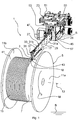
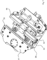
- the winding device according to the invention is generally provided with the reference numeral 1.
- the winding device 1 serves to wind a continuously extruded from an extrusion, not shown, plastic tube 3, such as a so-called cable protection tube on a winding drum 5, wherein a uniform possible winding without space between the individual winding loops 17 and with a substantially constant winding pitch of a plastic pipe width per Rotation should be achieved, as for example in the Figures 1 to 4b is shown.
- the winding drum 5 comprises a substantially cylindrical drum core 7, at the two axial ends of which in each case a lateral, radially extending side flange 11a, 11b is attached.
- a rotation axis 13 of the winding drum 5 is fixedly mounted (relative to a reference bottom B on which the winding device 1 stands) about which the winding drum 5 rotates to perform the winding operation.
- the axis of rotation 13 defines an axial direction, to which reference will also be made in the following to define movements of moving components of the winding device 1.
- the standardized winding drum 5 is often made of wood, wherein the drum core 7 and the side flanges 11a, 11b may differ slightly, but not negligibly from an ideal symmetrical shape.
- the cylindrical drum core 7 may have radial impacts, while the side flanges 11a, 11b may form axial imbalances.
- winding drums 5 made of other material, such as plastic often deviate from an ideal symmetric rotational shape at random or due to production.
- the extruded plastic tube 3 is already wound in an initial winding position by more than the axial half of the winding drum 5 to the drum core 7.
- the winding loop which has just been applied last to the drum core 7, shall be provided with the reference numeral 17.
- the winding loop 17 has, until the next winding loop is completely encircling and has applied laterally, a circumferential portion free axial lateral side 18, to which reference is made in the following mainly at an approximately 12 o'clock circumferential location (contact with the engagement wheel 43) shall be.
- the plastic pipe 3 is extruded continuously cylindrical along its extension and may have an outer diameter of 5 mm to 30 mm or 40 mm.
- the thickness of the plastic pipe 3 may be about 10% to 60% of the outer pipe radius.
- the plastic pipe 3 is continuously formed in an extrusion station (not shown) and passes through a cooling line (water bath) in the winding device 1, which may be preceded by a plastic pipe (3) buffer system (not shown), through the different conveying speeds of Plastic tube 3 to be compensated in the longitudinal direction during the extrusion process and during winding.
- the buffer system may for example be designed as a vertical pendulum, which can compensate for the vertical displacement of a diverter wheel too little / too high speed of the winding device 1 relative to the extruding device by the guide wheel occupies a higher / lower vertical position. In this way, a buffer line for the extruded plastic pipe (3) can be achieved for a continuous manufacturing process before it enters the winding device 1.
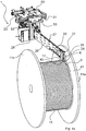
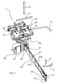
- the winding device 1 consists essentially of four main components, namely a carrier 23, a restoring device 61, a merely in FIG. 5 indicated positioning robot 71 and a laying arm 27 according to the invention.
- the laying arm 27 has the shape such as a chainsaw with a Verlegerearmbasis 28 (actuator / motor base) and a laying blade 29, which extends from the Verlegerearmbasis 28 substantially in the horizontal direction to the winding drum 5 and these touches directly or indirectly.
- the laying arm base 28 has on its end facing away from the winding drum 5 a receptacle 21 (FIG. FIGS. 6 . 9 and 10
- the receptacle 21 comprises star-shaped pairs of rollers 25 which delimit a threading opening to ensure a horizontally and vertically guided threading of the plastic pipe 3 into the laying arm 27.
- the laying arm base 28 is mainly formed by a profile support 57 which is composed of a plurality of mutually joined support plates. Functional components of the winding device 1, such as a microcomputer, actuators, etc., can be attached to the support plates.
- the carrier 23 movably supports the laying arm 27 and, in the illustrated embodiment, has a rail 51 to which a gripping arm of the setting robot 71 is attached.
- the rail 51 cooperates with a carriage 53 of the laying arm base 28 such that the laying arm 27 can be reciprocated along the linear carriage path.
- the laying blade 29 extends predominantly in a horizontal direction, approximately perpendicular to the axial direction 13 of the Verlegerearmbasis 28 away to the winding drum 5, wherein the laying arm 27 is dimensioned so that in the longitudinal direction over the drum core 7 (to about in the axial center) protrudes (considered in lifting direction A).
- the laying blade 29 has two vertical, mutually parallel guide and holding plates 31a, 31b. Between the two holding and guide plates 31a, 31b, which have a substantially constant vertical width in their essentially horizontal extension direction, a guide gap is formed for forming a transport space 32 for the plastic tube 3. In order that the plastic tube 3 can slide safely from the receptacle 21 along the laying arm 27 between the holding and guide plates 31a, 31b, guide rollers can be rotatably mounted in the guide gap on the holding and guiding plates 31a, 31b and a guide channel defined by the transport space 32 through.
- a winding material delivery 34 in particular in the form of a pair of delivery rollers 35 with horizontal axes of rotation is still stored in the transport space 34, which ensure guided delivery of the plastic pipe 3 from the winding drum-side end 33 of the laying arm 27 to the winding drum 5.
- the structure 30 may be bounded laterally by vertically arranged plates and limit the transport space 32.
- On the support structure 30 a plurality of guide rollers for carrying out the winding material are rotatably mounted.
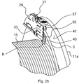
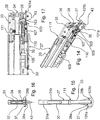
- a displacement sensor 36 is positioned in a first embodiment of a contactor 37.
- the contactor 37 comprises a freely rotatably mounted contact wheel whose axis of rotation is arranged vertically. Another known from the prior art displacement sensor can be used.
- the contact wheel has a passive operating state in the course of the laying movement W of the laying arm 27 between the left side flange 11b and the opposite right side flange 11a, in which the axis of rotation lies in a guide gap of the laying bar 29.
- the contactor 37 outputs an electrical contact signal to a control and / or regulating device (not shown), which processes the contact signal for the further winding operation of the winding device 1.
- the triggering of the electrical contact signal can be initiated and transmitted immediately after moving the contact wheel from its unactuated middle position or with a path-dependent delay after reaching a predetermined pivoting amplitude.
- a contact region 38 is formed, on which the winding drum-side end 33 of the laying arm can come into sliding contact with the side flange wall 11a, 11b of the winding drum 5.
- the pivot bearing 39 of the displacement sensor 34 is designed such that the contact wheel of the contactor 37 is pivoted away at least to the level of the outside of the respective abutment portion 38, so that the actuating projection of the contact wheel is completely sunk in the lateral direction and the respective abutment portion 38 is released .
- an engagement wheel 43 is mounted so as to be freely rotatably mounted on the laying arm 27 whose axis of rotation lies substantially horizontally parallel to the axis of rotation 13 of the winding drum 5.
- the running surface of the engagement wheel 43 is in direct rolling contact with the driven drum core 7 or an already placed winding position.
- a freely accessible side region of the engagement gear 43 abuts when winding with a predominantly axial pressure biasing contact on the axial lateral side 18 of the winding loop 17 last laid.
- the axial width of the tread of the engagement wheel 43 is dimensioned such that it is greater than half the outer diameter of the plastic tube 3, but smaller than the outer diameter of the plastic tube 3.
- the laying arm 27 is pivotally mounted vertically via a carrier-side (23) pivot bearing, which is not illustrated in detail, wherein a carrier-side pivot axis S horizontal, at least depending on the laying position parallel to the axis of rotation 13 of the winding drum 5 runs.
- a damping unit 45 is provided, which is fastened on the one hand to the carrier 23 and on the other hand to a projection 47 on the upper side of the laying bar 29.
- the damping unit 45 ensures a damped pivoting movement of the laying arm 27 about the carrier-side pivot axis S.
- a pivot stop (not shown) is provided, which limits pivoting of the laying arm 27 in the vertical plane down to the winding drum 5.
- the pivotal stop ensures that the engagement gear 43 does not press between two already laid winding loops and completely penetrates between them, in order to avoid contact engagement of the engagement wheel 43 with an underlying complete winding position.
- the pivoting mobility of the laying arm 27 and the position of the pivot stop are set relative to the laying arm 27 such that the engagement wheel 43 is in rolling contact in rolling contact with the cylindrical drum core 7 or the last laid winding position.
- the pivot stop stops a lowering of the engagement roller 43 from at most half the thickness of the plastic tube 3, so that a rolling contact on the last completely laid winding position is prevented.
- the carrier 23 is displaceable relative to the stationary rotational axis 13 or the stationary reference base B of a production hall by the positioning robot 71, which is fixedly mounted on the reference bottom B, the carrier 23 engages, holds and according to the winding process controls positioned.
- FIG. 5 are partially the axes of movement of the positioning robot 71, wherein the positioning robot 71 can move the carrier 23 in the horizontal direction, which corresponds to the axial direction (rotation axis 13) and substantially the laying direction V, and in lifting direction A linear and wherein the positioning robot 71, the carrier 23 to the lateral contact K (about the rotation axis D) can pivot.
- the point of engagement of the engagement wheel 43 with the drum core 7 or the winding position already laid forms an actuating point at which the laying arm 27 is axially displaced axially relative to the carrier 23 by the axial increase of the winding position 15.
- This may be referred to as a flexibly responding following movement of the laying arm 27, which immediately follows the continuous axial laying of the winding loops 17 and the axial growth of the winding layer 15.
- the Nachgebegraphy the laying arm 27 and the Nachstellterrorism the carrier 23 are with the double arrows V, A in FIG. 5 indicated.
- the positioning robot 71 holds the carrier 23 by means of the rail 51, which cooperates with the carriage 53, which is formed from a base plate 55 and a downwardly extending profile carrier 57.
- the carriage 53 and the rail 51 form a translatory bearing, the translational laying direction V is set substantially or approximately parallel to the horizontal axial direction (rotation axis 13).
- the carriage (53) rails (51) arrangement gives the laying arm 27 a freedom of movement relative to the carrier 23 only in the laying direction V, so that the carriage 53 only in the laying direction V relative to the positioning robot 71, in particular its gripping arm (not shown). , can be relocated.
- the rail (51) sled (53) arrangement provides axial compliance for the laying arm 27.
- the axial compliance is provided by the degree of freedom of movement in the laying direction V.
- the engagement wheel 43 in the laying process between the two side flanges 11a, 11b does not lose contact with the lateral side of the last winding loop 17, acts between the carriage 53 and the rail 51, a restoring or biasing means 61 which an elastic restoring or biasing force generated when the laying arm 27 from a predefined neutral position relative to the carrier 23, in which no restoring forces of the restoring device 61 between the rail 51 and the carriage 53 act in the laying direction V, driven by the axial expansion of the winding layer 15, is deflected.
- the amount of the restoring force is greater, the greater the deflection of the laying arm 27 from the neutral position.
- the return device 61 is formed by a pair of pneumatic actuators 63, 65, whose details in the FIGS. 7 to 10 are indicated.
- a pneumatic actuator 65 or 63 is active for generating the restoring force only in one of the laying directions V (for example, from the side flange 11a to the side flange 11b), while the other pneumatic actuator (65 or 63) in the opposite laying direction V (from the side flange 11b to the side flange 11a) is active.
- the end 33 of the laying arm 27 together with the slide 53 moves in a linear laying direction V relative to the rail 51, which is unaffected in the meantime stationary provisionally remains in its position until it is adjusted, for example, when exceeding a deflection threshold of the carriage 53 by the positioning robot 71, which reduces the restoring force of the return device.
- the pneumatic actuator 63 or 65 (depending on the axial laying direction) pneumatically clamped, so that in the pneumatic actuator 63, 65, the pneumatically elastic restoring force is generated, which via the carriage 53 to the laying arm 27 is communicated and finally the sprocket 43 biases axially against the free lateral side 18 of the last wound winding loop 17.
- the axial return bias ensures that all winding loops 17 are placed close together in the axial direction to achieve the desired uniform winding sequence, and can be flexibly adapted to geometrical and material-specific anomalies.
- the pneumatic actuator 63, 65 can also generate independently of the laying of the laying arm 27 an actively controlled, pneumatic restoring force, for example by the pneumatic actuator via a control and / or regulating device, not shown, for example, depending on a predetermined operating condition is pneumatically activated.
- the pneumatic actuator 63 is uncontrolled and builds up (only) elastic restoring forces when the laying arm 27 is moved out of its neutral position in the laying direction V.
- the axial deflection between the carriage 53 and the rail 51 is kept substantially constant or at least in a boundary region.
- an unillustrated position sensor is used, which monitors a predefined minimum and maximum Sollausschamplitude by means of a control and / or regulating device (not shown in detail). If this is exceeded or fallen short of, the positioning robot 71 follows the rail 51 following the deflection movement of the laying arm 27, wherein the Nachschreib intimid can correspond approximately to a thickness of the plastic pipe 3. In this way, it is ensured that the elastic restoring force is reduced by the trailing of the rail 51 by the periodic structure of the deflection.
- the plastic tube 3 when winding around the drum core 7 as far as possible claimed in the longitudinal direction with a constant tensile prestressing force.
- an electromagnetic brake in particular an eddy current brake 67
- the carrier 23 in particular on the carriage 53, which consists of an active operating position, as shown in FIG FIG. 10 it can be seen in a passive operating position (see FIG. 9 ) can be spent.
- the eddy current brake 67 which may optionally be provided and manipulated by an unspecified control and / or regulating device, serves to communicate the substantially uniform tensile prestressing force to the plastic pipe 3.
- the eddy current brake 67 may include two magnet rotors that rotate in an electromagnetically generated magnetic field, wherein the respective magnet rotor may be retracted and extended to adjust the electromagnetic braking force.
- a toothed belt 72 is provided, which is stretched around two pulleys of the eddy current brake 67.
- the timing belt 72 has transverse teeth to ensure a desired engagement with the plastic pipe 3 and the friction force transmission.
- the belt 72 may also be provided a longitudinally extending mountain-valley profile, which is shaped complementary to the plastic pipe 3.
- FIG. 2a and 2 B is an operating condition can be seen in which a first winding layer 15 is approximately completed on the drum core 7.
- the engagement wheel 43 runs on the cylindrical drum core 7, wherein the axial restoring force generated by the restoring device 61 presses the winding loop 17 just laid down axially against the adjacent winding loop.
- the contact wheel of the contactor 37 comes into rolling engagement with the inside 41 of the side flange 11a. With continuation of the winding process, the contact wheel is deflected horizontally, whereby the control signal of the contactor 37 is sent to a control and / or regulating device, not shown.
- FIG. 6 it can be seen that the laying arm 27 at its in FIG. 6 shown axial end position to the horizontal radial direction H R is inclined at an angle ⁇ , according to which the laying arm 27 is inclined starting from the winding drum side end 33 of the right side flange 11a towards the winding drum center.
- This ensures that the contact wheel of the contactor 37 has sufficient space for pivoting to the Control signal to generate and deliver without the end 33 of the laying arm 27 comes into contact conflict with the inside 41 of the side flange 11a, 11b.
- the radially extending side flange 11a, 11b does not interfere with the inclined laying arm 27.
- control and / or regulating device can be used exclusively for the angular velocity of the winding drum 5 in dependence of the radial and / or axial position of the guide (the laying arm 27), in particular its winding drum end 33, adjust. It is clear that the control and / or regulating device can also assume the above-mentioned control functions. Preferably, the control and / or regulating device is firmly connected to the base plate 55. However, other mounting locations for the control and / or regulating device may also be considered.
- the leading end of the plastic pipe is first threaded through an opening in the side flange 11 of the winding drum 5 and immediately adjacent to the inside 41 of the side flange 11a, 11b manually by an operator for the first winding layer at a low Angular velocity (see FIG. 11 ; START), with the angular velocity U gradually increasing.
- the displacement detection of the laying arm 27 in the control and / or regulating device is initialized, namely set to "0". From this initialization of the laying process (at START according to FIG. 11 ) begins a particular continuous Detecting the position of the laying arm 27.
- the winding speed U is increased to a maximum winding speed U max , so that from a variable or pre-fixed Stellpositon X 1 for the first winding layer 15, the maximum winding speed U max is reached.
- the helical laying of the winding layer 15 in the so-called axial center region C of the winding drum 5 see FIG.
- the control triggers and / or regulating device a so-called Soflansch- or turning operation, in which first the angular velocity is reduced gradually, namely to a minimum angular velocity U min , which is to be kept constant during the further delicate wall operation (X 3 -X 4 ) ( Fig. 11 ).
- the winding speed between X 4 and X 5 according to the previous winding speed decrease between X 2 and X 3 is continuously steadily increasing and reaches the maximum angular velocity U max in the setting position X 5 , which may be predetermined or calculated during the winding process.
- the setting positions can either be predetermined by input to the control and / or regulating device, or calculated during the winding process and changed depending on the winding progress.
- FIG. 12 is the turning operation illustrated by a path-time diagram in which the axial displacement X is shown with respect to the time t.
- the time t 0 is decisive.
- a stepped graphene form can be seen, in which the stepwise advancement of the laying arm 27 is to be illustrated in the axial direction relative to the leading winding layer during the normal winding operation. It is clear that no step shape is necessary, but also other curved paths are possible.
- axial restoring forces which urge the laying arm 27 against the free lateral side 18 of the last winding loop are built up by advancing the laying arm 27 relative to the support 23 of the guide in the axial direction X by the progress of the winding; the coil winding, which builds up axially, presses the laying arm 27 against the elastic pretensioning device acting within the guide, as a result of which elastic restoring forces build up due to the relative movement.
- the turning operation Upon reaching the turning position X 0 at the time t 0 , the turning operation is triggered. If the reversing position X 0 is reached, the control and / or regulating device causes a vertical free travel of the laying arm 27 away from the winding drum 5, and experience has shown that a radial clearance of 30 mm is sufficient to compensate for maximum radial balancing of the drum core 7 of the winding drum 5. Essential in the free movement of the laying arm 27 is to always make the drum-side end 33 contactless to the last laid winding layer 15.
- the laying arm 27 is not displaced in the axial direction and remains at the turning position X 0 . Until the time t 1 , the axial distance (X) does not change.
- FIG. 11 and FIG. 12 are related insofar as the turning position X 0 according to FIG. 12 essentially the position X 2 or X 6 according to FIG. 11 equivalent.
- the angular velocity U remains unchanged.
- the carrier 23 and thus the laying arm 27 (whose end 33 is no longer resting on the laid winding layer) are advanced further in the axial direction towards the side wall flange 11a, 11b of the winding drum 5, in order to completely abut the winding drum end 33 of the laying arm 27 on the side wall flange 11a, 11b always ensure during the entire circulation of the winding drum 5.
- the axial advance path is in FIG. 12 with X 0 to X 1 illustrated. After completion of the advance at time t 2 , the winding drum 5 can be further rotated by about 0.4 turns.
- a position correction of the laying arm 27 and the carrier 23 can be performed, for example, to adjust the restoring forces in the rail carriage storage or to change the position of the laying arm 27 relative to the winding drum 5 ,
- the correction phase may take about 0.6 revolutions of the winding drum 5.
- the guide namely the carrier 23 together with the laying arm 27, is set in the direction of insertion movement direction opposite Her laying movement direction to make the laying arm 27 with respect to the sowandflansches 11 a, 11 b of the winding drum 5 contactless.
- the return return path is approximately equal to the advance travel, but can also be realized larger or smaller, so that it is ensured that the winding drum end 33 of the laying arm 27 no longer reaches the contact area of the side wall flange 11a, 11b of the winding drum 5.
- the return can take about 0.2 revolutions of the winding drum 5.
- the axial displacement X refers to the actuating movement of the carrier 23, wherein the displacement of the carrier 23 by the positioning robot 71 and the flexible displacement of the laying arm 27 due to the sliding bearing on the carrier 23 and the winding progress in the case is about the same the laying arm 27 is not supported on the side wall flange 11a, 11b of the winding drum 5 or the lateral side of the last winding loop.
- FIGS. 13 to 18 Details of a preferred embodiment of the laying arm 27 according to the invention are shown, wherein for similar or identical components of the laying arm 27, which was previously described with reference to the previous figures, the same reference numerals are used to facilitate the readability of the figure description.
- the laying arm 27 comprises three main components, namely the arm base 28, at which the winding material is introduced, the winding drum end 33, on which the winding material is discharged, and an intermediate elongate support structure 30, which forms the majority of the laying arm 27.
- the winding drum-side end 33 is releasably and interchangeably-connected via interfaces 110, 111 with the structure 30. In this way, it is sufficient, when changing the dimension of the winding material, only to exchange the winding drum-side end 33 for a dimension-adapted, while all other components (28, 30) of the laying arm 27 can be maintained. These other components are independent of the dimension of the winding material. Only the winding drum-side end 33 is winding material specific due to the contactor 37, which will be explained below as an alternative embodiment, and the winding material delivery 34 executed.
- the contactor 37 is formed in an alternative embodiment without contact wheel, but realized with running on the soflanschwand 11a, 11b expiring actuating projections 101a, 101b.
- the actuating projections 101a, 101b are part of a closed bow or ring structure of the contactor 37, which in plan view has a triangular shape with two equal length long legs, which lie at an angle of about 15 ° to the longitudinal direction of the laying arm 27.
- the long legs extend to a connecting front short leg, which forms the free end of the contactor 37 and the winding drum end 33. Corners of the triangular ring structure are rounded.
- the actuating projections 101a, 101b are pivotally mounted together with the ring structure about a vertically extending pivot axis 100, so that the respective actuating projections 101a, 101b respectively with the respective sowandflansch 11a, 11b are pivotally retractable such that its corner at the level of the outer surface of the contact area 38a, 38b and no distance projects laterally beyond the outer surface.
- the abutment region 38 of the winding drum-side end 33 of the laying arm 27 contacts the inside of the respective side flange wall 11a, 11b.
- a non-illustrated coercion means such as a spring, preferably a torsion spring.
- the spring preload can directly engage the ring structure or on a gear part, such as the pivot axis 100, etc.
- the contactor 37 is provided with an angle gear 103 for transmitting the pivotal movement of the vertical pivot axis 100, which is rigidly coupled to the ring structure, into pivotal movement about a transmission shaft 105 extending in the longitudinal direction of the laying arm 27.
- the translation of the angular gear 103 for transmitting the pivoting movement is preferably 1: 1.
- a signal generator (not shown) arranged on the supporting structure 30 is coupled to the transmission shaft 105 and outputs an electrical control signal after the start of movement or after exceeding a predetermined swing amplitude of the ring structure in order to inform the control and / or regulating device that the turning operation is to be initiated.
- the control signal can be triggered immediately at the start of the swing or only delayed after reaching a predetermined swing amplitude.
- the transmission shaft 105 is divided into two, with the path sensor-side shaft portion 107 coupled to the support (30) side shaft portion 109 by means of a releasable dog clutch 110 that allows disassembly of the front and rear shaft portions 107, 109 from each other.
- a releasable dog clutch 110 that allows disassembly of the front and rear shaft portions 107, 109 from each other.
- the guide and holding plates 31b and 31a form a separable interface 111 for separating a housing plate portion facing the winding drum 5 from a base-side housing plate portion.
- the mounting interfaces (110, 111) allow the winding drum end 33 together with its functional elements, such as the Wickelgutabgabe 34, Abgabelig 35, Kunststoffgebermaschine and decouple the mechanical communication of the contactor 37 toward the signal generator to the device of the invention and in particular the majority of Verlegearms invention 27 to adapt depending on the application for a certain sized winding material. It has been found that those components in the transport space 32 on this side of the mounting interfaces (110, 111) can be interpreted for a large number of different sized winding goods, but the winding drum-side end 33 is to be adapted to the winding material specific to the dimensioning. In particular, the winding material delivery 34 and the actuation projections 101a, 101b projecting from the abutment region 38 can be adapted to the winding material thickness.
- the winding material delivery 34 and the actuation projections 101a, 101b projecting from the abutment region 38 can be adapted to the winding material thickness.
- an exchange of the winding drum end 33 can be done purely mechanically, whereby even inexperienced operators can perform a change of the winding drum end 33 for adjusting the laying arm 27 to be wound winding.
Landscapes
- Storing, Repeated Paying-Out, And Re-Storing Of Elongated Articles (AREA)
- Tyre Moulding (AREA)
- Winding Of Webs (AREA)
Priority Applications (1)
| Application Number | Priority Date | Filing Date | Title |
|---|---|---|---|
| PL15701478T PL3099614T3 (pl) | 2014-01-28 | 2015-01-28 | Ramię do układania dla urządzenia do nawijania pasmowego materiału nawijanego |
Applications Claiming Priority (3)
| Application Number | Priority Date | Filing Date | Title |
|---|---|---|---|
| DE102014001057.0A DE102014001057A1 (de) | 2014-01-28 | 2014-01-28 | Verlegearm für eine Vorrichtung zum Wickeln eines strangförmigen Wickelguts |
| DE102014001135.6A DE102014001135B3 (de) | 2014-01-28 | 2014-01-28 | Verlegearm für eine Vorrichtung zum Wickeln eines strangförmigen Wickelguts |
| PCT/EP2015/000164 WO2015113763A1 (de) | 2014-01-28 | 2015-01-28 | Verlegearm für eine vorrichtung zum wickeln eines strangförmigen wickelguts |
Publications (2)
| Publication Number | Publication Date |
|---|---|
| EP3099614A1 EP3099614A1 (de) | 2016-12-07 |
| EP3099614B1 true EP3099614B1 (de) | 2018-12-12 |
Family
ID=52432782
Family Applications (1)
| Application Number | Title | Priority Date | Filing Date |
|---|---|---|---|
| EP15701478.8A Active EP3099614B1 (de) | 2014-01-28 | 2015-01-28 | Verlegearm für eine vorrichtung zum wickeln eines strangförmigen wickelguts |
Country Status (7)
| Country | Link |
|---|---|
| EP (1) | EP3099614B1 (es) |
| DK (1) | DK3099614T3 (es) |
| ES (1) | ES2724461T3 (es) |
| HU (1) | HUE041608T2 (es) |
| PL (1) | PL3099614T3 (es) |
| PT (1) | PT3099614T (es) |
| WO (1) | WO2015113763A1 (es) |
Families Citing this family (3)
| Publication number | Priority date | Publication date | Assignee | Title |
|---|---|---|---|---|
| CN109928265B (zh) * | 2019-04-03 | 2023-10-31 | 山东海岱智能设备有限公司 | 用于打轴机双向摆动机构的平衡装置 |
| CN114620546B (zh) * | 2022-03-29 | 2023-08-25 | 南通禾欧服饰有限公司 | 一种络筒机用绕线管筒的固定设备 |
| EP4375223A1 (en) | 2022-11-24 | 2024-05-29 | Techspeed Bendkowski, Mazur sp.j. | Autonomous device for winding cable wires |
Family Cites Families (10)
| Publication number | Priority date | Publication date | Assignee | Title |
|---|---|---|---|---|
| GB836412A (en) * | 1956-05-18 | 1960-06-01 | British Insulated Callenders | Improvements in or relating to apparatus for reeling electric cables and other elongated flexible articles |
| AU495293B2 (en) * | 1974-08-27 | 1976-03-04 | Sumitomo Electric Industries, Ltd. | Automatic cable winding apparatus |
| FI67350C (fi) * | 1983-11-22 | 1985-03-11 | Nokia Oy Ab | Styranordning foer en foerdelningsapparat foer spolning av en kabel pao en flaensfoersedd trumma |
| SE8601484L (sv) | 1985-04-29 | 1986-10-30 | Skaltek Ab | Arm for upplindning av en kabel |
| DE3612743A1 (de) * | 1986-04-16 | 1987-10-22 | Prym Werke William | Verlegeeinrichtung fuer spulmaschinen |
| DE102013002019A1 (de) | 2013-02-06 | 2014-08-07 | Gabo Systemtechnik Gmbh | Wickelungsvorrichtung für ein strangförmiges Wickelgut und Verfahren dazu |
| DE102013002023A1 (de) | 2013-02-06 | 2014-08-07 | Gabo Systemtechnik Gmbh | Vorrichtung und Verfahren zum Wickeln eines strangförmigen Wickelguts |
| DE102013002017A1 (de) | 2013-02-06 | 2014-08-07 | Gabo Systemtechnik Gmbh | Wickelungsvorrichtung und -verfahren für ein strangförmiges Wickelgut |
| DE102013002022A1 (de) | 2013-02-06 | 2014-08-07 | Gabo Systemtechnik Gmbh | Vorrichtung zum Wickeln eines strangförmigen Wickelguts und Verfahren dazu |
| DE102013002020B4 (de) | 2013-02-06 | 2023-02-09 | Gabo Systemtechnik Gmbh | Wickelungsvorrichtung und Wickelungsverfahren für ein strangförmiges Wickelgut |
-
2015
- 2015-01-28 EP EP15701478.8A patent/EP3099614B1/de active Active
- 2015-01-28 HU HUE15701478A patent/HUE041608T2/hu unknown
- 2015-01-28 PL PL15701478T patent/PL3099614T3/pl unknown
- 2015-01-28 DK DK15701478.8T patent/DK3099614T3/en active
- 2015-01-28 ES ES15701478T patent/ES2724461T3/es active Active
- 2015-01-28 PT PT15701478T patent/PT3099614T/pt unknown
- 2015-01-28 WO PCT/EP2015/000164 patent/WO2015113763A1/de active Application Filing
Non-Patent Citations (1)
| Title |
|---|
| None * |
Also Published As
| Publication number | Publication date |
|---|---|
| DK3099614T3 (en) | 2019-03-18 |
| HUE041608T2 (hu) | 2019-05-28 |
| WO2015113763A1 (de) | 2015-08-06 |
| PL3099614T3 (pl) | 2019-05-31 |
| EP3099614A1 (de) | 2016-12-07 |
| ES2724461T3 (es) | 2019-09-11 |
| PT3099614T (pt) | 2019-03-25 |
Similar Documents
| Publication | Publication Date | Title |
|---|---|---|
| DE102013002020B4 (de) | Wickelungsvorrichtung und Wickelungsverfahren für ein strangförmiges Wickelgut | |
| DE102014001134B4 (de) | Wickelungsvorrichtung für ein strangförmiges Wickelgut und Verfahren dazu | |
| DE102013002017A1 (de) | Wickelungsvorrichtung und -verfahren für ein strangförmiges Wickelgut | |
| DE69507490T2 (de) | Verfahren und vorrichtung zum aufwickeln einer laufenden bahn in eine bahnrolle | |
| EP3180283B1 (de) | Spulvorrichtung zum spulen eines wickelguts und verfahren zum betrieb einer spulvorrichtung zum spulen eines wickelguts | |
| EP3099614B1 (de) | Verlegearm für eine vorrichtung zum wickeln eines strangförmigen wickelguts | |
| DE102013002022A1 (de) | Vorrichtung zum Wickeln eines strangförmigen Wickelguts und Verfahren dazu | |
| DE2917295A1 (de) | Wickelsystem fuer metallische straenge | |
| DE68922482T2 (de) | Auflegevorrichtung für gummierte Bahnen. | |
| DE102012005374A1 (de) | Spulenwechselvorrichtung | |
| DE102013002023A1 (de) | Vorrichtung und Verfahren zum Wickeln eines strangförmigen Wickelguts | |
| EP3099613B1 (de) | Vorrichtung und verfahren zum wickeln eines strangförmigen wickelguts | |
| DE2816840C2 (es) | ||
| DE102013002019A1 (de) | Wickelungsvorrichtung für ein strangförmiges Wickelgut und Verfahren dazu | |
| AT412622B (de) | Greifzangenanordnung für roboteranlagen | |
| DE102014001135B3 (de) | Verlegearm für eine Vorrichtung zum Wickeln eines strangförmigen Wickelguts | |
| DE102014001058B4 (de) | Vorrichtung und Verfahren zum Wickeln eines strangförmigen Wickelguts | |
| EP3173217A1 (de) | Ablegeeinheit, vorrichtung und verfahren zum herstellen eines faserverbundbauteils | |
| DE2526962A1 (de) | Wickeltraeger | |
| EP2953876B1 (de) | Vorrichtung und verfahren zum wickeln eines strangförmigen wickelguts | |
| DE102011001835A1 (de) | Verfahren und Vorrichtung zur Verarbeitung eines Bandes | |
| DE102014001057A1 (de) | Verlegearm für eine Vorrichtung zum Wickeln eines strangförmigen Wickelguts | |
| EP2750995A1 (de) | Doppeltragwalzenroller | |
| DE2741534C2 (de) | Verfahren zum Herstellen von Schraubenfedern mit ösen aus Draht und Maschine zur Durchführung des Verfahrens | |
| EP4067274B1 (de) | Sicheres handhaben von hülsen oder metallbunden mit kleinem aussendurchmesser an einem haspeldorn |
Legal Events
| Date | Code | Title | Description |
|---|---|---|---|
| PUAI | Public reference made under article 153(3) epc to a published international application that has entered the european phase |
Free format text: ORIGINAL CODE: 0009012 |
|
| STAA | Information on the status of an ep patent application or granted ep patent |
Free format text: STATUS: REQUEST FOR EXAMINATION WAS MADE |
|
| 17P | Request for examination filed |
Effective date: 20160531 |
|
| AK | Designated contracting states |
Kind code of ref document: A1 Designated state(s): AL AT BE BG CH CY CZ DE DK EE ES FI FR GB GR HR HU IE IS IT LI LT LU LV MC MK MT NL NO PL PT RO RS SE SI SK SM TR |
|
| AX | Request for extension of the european patent |
Extension state: BA ME |
|
| DAX | Request for extension of the european patent (deleted) | ||
| GRAP | Despatch of communication of intention to grant a patent |
Free format text: ORIGINAL CODE: EPIDOSNIGR1 |
|
| STAA | Information on the status of an ep patent application or granted ep patent |
Free format text: STATUS: GRANT OF PATENT IS INTENDED |
|
| INTG | Intention to grant announced |
Effective date: 20180126 |
|
| GRAS | Grant fee paid |
Free format text: ORIGINAL CODE: EPIDOSNIGR3 |
|
| GRAJ | Information related to disapproval of communication of intention to grant by the applicant or resumption of examination proceedings by the epo deleted |
Free format text: ORIGINAL CODE: EPIDOSDIGR1 |
|
| GRAL | Information related to payment of fee for publishing/printing deleted |
Free format text: ORIGINAL CODE: EPIDOSDIGR3 |
|
| STAA | Information on the status of an ep patent application or granted ep patent |
Free format text: STATUS: REQUEST FOR EXAMINATION WAS MADE |
|
| GRAP | Despatch of communication of intention to grant a patent |
Free format text: ORIGINAL CODE: EPIDOSNIGR1 |
|
| STAA | Information on the status of an ep patent application or granted ep patent |
Free format text: STATUS: GRANT OF PATENT IS INTENDED |
|
| INTC | Intention to grant announced (deleted) | ||
| INTG | Intention to grant announced |
Effective date: 20180619 |
|
| GRAA | (expected) grant |
Free format text: ORIGINAL CODE: 0009210 |
|
| STAA | Information on the status of an ep patent application or granted ep patent |
Free format text: STATUS: THE PATENT HAS BEEN GRANTED |
|
| AK | Designated contracting states |
Kind code of ref document: B1 Designated state(s): AL AT BE BG CH CY CZ DE DK EE ES FI FR GB GR HR HU IE IS IT LI LT LU LV MC MK MT NL NO PL PT RO RS SE SI SK SM TR |
|
| REG | Reference to a national code |
Ref country code: GB Ref legal event code: FG4D Free format text: NOT ENGLISH |
|
| REG | Reference to a national code |
Ref country code: CH Ref legal event code: EP |
|
| REG | Reference to a national code |
Ref country code: AT Ref legal event code: REF Ref document number: 1075712 Country of ref document: AT Kind code of ref document: T Effective date: 20181215 |
|
| REG | Reference to a national code |
Ref country code: DE Ref legal event code: R096 Ref document number: 502015007182 Country of ref document: DE |
|
| REG | Reference to a national code |
Ref country code: IE Ref legal event code: FG4D Free format text: LANGUAGE OF EP DOCUMENT: GERMAN |
|
| REG | Reference to a national code |
Ref country code: CH Ref legal event code: NV Representative=s name: TROESCH SCHEIDEGGER WERNER AG, CH |
|
| REG | Reference to a national code |
Ref country code: DK Ref legal event code: T3 Effective date: 20190311 |
|
| REG | Reference to a national code |
Ref country code: PT Ref legal event code: SC4A Ref document number: 3099614 Country of ref document: PT Date of ref document: 20190325 Kind code of ref document: T Free format text: AVAILABILITY OF NATIONAL TRANSLATION Effective date: 20190312 |
|
| REG | Reference to a national code |
Ref country code: SE Ref legal event code: TRGR |
|
| REG | Reference to a national code |
Ref country code: NL Ref legal event code: FP |
|
| REG | Reference to a national code |
Ref country code: LT Ref legal event code: MG4D |
|
| PG25 | Lapsed in a contracting state [announced via postgrant information from national office to epo] |
Ref country code: HR Free format text: LAPSE BECAUSE OF FAILURE TO SUBMIT A TRANSLATION OF THE DESCRIPTION OR TO PAY THE FEE WITHIN THE PRESCRIBED TIME-LIMIT Effective date: 20181212 Ref country code: LT Free format text: LAPSE BECAUSE OF FAILURE TO SUBMIT A TRANSLATION OF THE DESCRIPTION OR TO PAY THE FEE WITHIN THE PRESCRIBED TIME-LIMIT Effective date: 20181212 Ref country code: LV Free format text: LAPSE BECAUSE OF FAILURE TO SUBMIT A TRANSLATION OF THE DESCRIPTION OR TO PAY THE FEE WITHIN THE PRESCRIBED TIME-LIMIT Effective date: 20181212 Ref country code: BG Free format text: LAPSE BECAUSE OF FAILURE TO SUBMIT A TRANSLATION OF THE DESCRIPTION OR TO PAY THE FEE WITHIN THE PRESCRIBED TIME-LIMIT Effective date: 20190312 |
|
| REG | Reference to a national code |
Ref country code: NO Ref legal event code: T2 Effective date: 20181212 |
|
| REG | Reference to a national code |
Ref country code: HU Ref legal event code: AG4A Ref document number: E041608 Country of ref document: HU |
|
| PG25 | Lapsed in a contracting state [announced via postgrant information from national office to epo] |
Ref country code: GR Free format text: LAPSE BECAUSE OF FAILURE TO SUBMIT A TRANSLATION OF THE DESCRIPTION OR TO PAY THE FEE WITHIN THE PRESCRIBED TIME-LIMIT Effective date: 20190313 Ref country code: AL Free format text: LAPSE BECAUSE OF FAILURE TO SUBMIT A TRANSLATION OF THE DESCRIPTION OR TO PAY THE FEE WITHIN THE PRESCRIBED TIME-LIMIT Effective date: 20181212 Ref country code: RS Free format text: LAPSE BECAUSE OF FAILURE TO SUBMIT A TRANSLATION OF THE DESCRIPTION OR TO PAY THE FEE WITHIN THE PRESCRIBED TIME-LIMIT Effective date: 20181212 |
|
| PG25 | Lapsed in a contracting state [announced via postgrant information from national office to epo] |
Ref country code: SM Free format text: LAPSE BECAUSE OF FAILURE TO SUBMIT A TRANSLATION OF THE DESCRIPTION OR TO PAY THE FEE WITHIN THE PRESCRIBED TIME-LIMIT Effective date: 20181212 Ref country code: EE Free format text: LAPSE BECAUSE OF FAILURE TO SUBMIT A TRANSLATION OF THE DESCRIPTION OR TO PAY THE FEE WITHIN THE PRESCRIBED TIME-LIMIT Effective date: 20181212 Ref country code: IS Free format text: LAPSE BECAUSE OF FAILURE TO SUBMIT A TRANSLATION OF THE DESCRIPTION OR TO PAY THE FEE WITHIN THE PRESCRIBED TIME-LIMIT Effective date: 20190412 Ref country code: SK Free format text: LAPSE BECAUSE OF FAILURE TO SUBMIT A TRANSLATION OF THE DESCRIPTION OR TO PAY THE FEE WITHIN THE PRESCRIBED TIME-LIMIT Effective date: 20181212 Ref country code: RO Free format text: LAPSE BECAUSE OF FAILURE TO SUBMIT A TRANSLATION OF THE DESCRIPTION OR TO PAY THE FEE WITHIN THE PRESCRIBED TIME-LIMIT Effective date: 20181212 |
|
| REG | Reference to a national code |
Ref country code: ES Ref legal event code: FG2A Ref document number: 2724461 Country of ref document: ES Kind code of ref document: T3 Effective date: 20190911 |
|
| REG | Reference to a national code |
Ref country code: DE Ref legal event code: R097 Ref document number: 502015007182 Country of ref document: DE |
|
| PLBE | No opposition filed within time limit |
Free format text: ORIGINAL CODE: 0009261 |
|
| STAA | Information on the status of an ep patent application or granted ep patent |
Free format text: STATUS: NO OPPOSITION FILED WITHIN TIME LIMIT |
|
| PG25 | Lapsed in a contracting state [announced via postgrant information from national office to epo] |
Ref country code: MC Free format text: LAPSE BECAUSE OF FAILURE TO SUBMIT A TRANSLATION OF THE DESCRIPTION OR TO PAY THE FEE WITHIN THE PRESCRIBED TIME-LIMIT Effective date: 20181212 Ref country code: SI Free format text: LAPSE BECAUSE OF FAILURE TO SUBMIT A TRANSLATION OF THE DESCRIPTION OR TO PAY THE FEE WITHIN THE PRESCRIBED TIME-LIMIT Effective date: 20181212 |
|
| 26N | No opposition filed |
Effective date: 20190913 |
|
| PG25 | Lapsed in a contracting state [announced via postgrant information from national office to epo] |
Ref country code: TR Free format text: LAPSE BECAUSE OF FAILURE TO SUBMIT A TRANSLATION OF THE DESCRIPTION OR TO PAY THE FEE WITHIN THE PRESCRIBED TIME-LIMIT Effective date: 20181212 |
|
| PG25 | Lapsed in a contracting state [announced via postgrant information from national office to epo] |
Ref country code: MT Free format text: LAPSE BECAUSE OF FAILURE TO SUBMIT A TRANSLATION OF THE DESCRIPTION OR TO PAY THE FEE WITHIN THE PRESCRIBED TIME-LIMIT Effective date: 20181212 |
|
| PG25 | Lapsed in a contracting state [announced via postgrant information from national office to epo] |
Ref country code: CY Free format text: LAPSE BECAUSE OF FAILURE TO SUBMIT A TRANSLATION OF THE DESCRIPTION OR TO PAY THE FEE WITHIN THE PRESCRIBED TIME-LIMIT Effective date: 20181212 |
|
| PG25 | Lapsed in a contracting state [announced via postgrant information from national office to epo] |
Ref country code: MK Free format text: LAPSE BECAUSE OF FAILURE TO SUBMIT A TRANSLATION OF THE DESCRIPTION OR TO PAY THE FEE WITHIN THE PRESCRIBED TIME-LIMIT Effective date: 20181212 |
|
| P01 | Opt-out of the competence of the unified patent court (upc) registered |
Effective date: 20230527 |
|
| REG | Reference to a national code |
Ref country code: DE Ref legal event code: R082 Ref document number: 502015007182 Country of ref document: DE Representative=s name: SKM-IP SCHMID KRAUSS KUTTENKEULER MALESCHA SCH, DE |
|
| PGFP | Annual fee paid to national office [announced via postgrant information from national office to epo] |
Ref country code: NL Payment date: 20240123 Year of fee payment: 10 |
|
| PGFP | Annual fee paid to national office [announced via postgrant information from national office to epo] |
Ref country code: LU Payment date: 20240122 Year of fee payment: 10 |
|
| PGFP | Annual fee paid to national office [announced via postgrant information from national office to epo] |
Ref country code: IE Payment date: 20240118 Year of fee payment: 10 Ref country code: ES Payment date: 20240216 Year of fee payment: 10 |
|
| PGFP | Annual fee paid to national office [announced via postgrant information from national office to epo] |
Ref country code: AT Payment date: 20240118 Year of fee payment: 10 |
|
| PGFP | Annual fee paid to national office [announced via postgrant information from national office to epo] |
Ref country code: HU Payment date: 20240125 Year of fee payment: 10 Ref country code: FI Payment date: 20240119 Year of fee payment: 10 Ref country code: DE Payment date: 20240119 Year of fee payment: 10 Ref country code: CZ Payment date: 20240118 Year of fee payment: 10 Ref country code: GB Payment date: 20240124 Year of fee payment: 10 Ref country code: CH Payment date: 20240201 Year of fee payment: 10 Ref country code: PT Payment date: 20240116 Year of fee payment: 10 |
|
| PGFP | Annual fee paid to national office [announced via postgrant information from national office to epo] |
Ref country code: SE Payment date: 20240123 Year of fee payment: 10 Ref country code: PL Payment date: 20240117 Year of fee payment: 10 Ref country code: NO Payment date: 20240122 Year of fee payment: 10 Ref country code: IT Payment date: 20240131 Year of fee payment: 10 Ref country code: FR Payment date: 20240123 Year of fee payment: 10 Ref country code: DK Payment date: 20240123 Year of fee payment: 10 Ref country code: BE Payment date: 20240122 Year of fee payment: 10 |