EP3099345B1 - Queue de cochon pour imagerie et alignement complexes valvulaires aortiques optimaux - Google Patents
Queue de cochon pour imagerie et alignement complexes valvulaires aortiques optimaux Download PDFInfo
- Publication number
- EP3099345B1 EP3099345B1 EP15743048.9A EP15743048A EP3099345B1 EP 3099345 B1 EP3099345 B1 EP 3099345B1 EP 15743048 A EP15743048 A EP 15743048A EP 3099345 B1 EP3099345 B1 EP 3099345B1
- Authority
- EP
- European Patent Office
- Prior art keywords
- distal
- catheter
- branches
- outer sheath
- lumen
- Prior art date
- Legal status (The legal status is an assumption and is not a legal conclusion. Google has not performed a legal analysis and makes no representation as to the accuracy of the status listed.)
- Active
Links
- 238000003384 imaging method Methods 0.000 title description 45
- 230000002093 peripheral effect Effects 0.000 claims description 56
- 239000000994 contrast dye Substances 0.000 claims description 38
- 239000003550 marker Substances 0.000 claims description 18
- 210000003709 heart valve Anatomy 0.000 claims description 12
- 229940079593 drug Drugs 0.000 claims description 6
- 239000003814 drug Substances 0.000 claims description 6
- 210000001765 aortic valve Anatomy 0.000 description 112
- 238000000034 method Methods 0.000 description 58
- 238000012384 transportation and delivery Methods 0.000 description 17
- 238000013158 balloon valvuloplasty Methods 0.000 description 13
- 238000002560 therapeutic procedure Methods 0.000 description 10
- 239000000463 material Substances 0.000 description 9
- 241001465754 Metazoa Species 0.000 description 8
- 230000002792 vascular Effects 0.000 description 8
- 208000031481 Pathologic Constriction Diseases 0.000 description 7
- 230000036262 stenosis Effects 0.000 description 7
- 208000037804 stenosis Diseases 0.000 description 7
- 241000282412 Homo Species 0.000 description 6
- 230000008901 benefit Effects 0.000 description 6
- 201000010099 disease Diseases 0.000 description 6
- 208000037265 diseases, disorders, signs and symptoms Diseases 0.000 description 6
- 239000000975 dye Substances 0.000 description 6
- 238000002513 implantation Methods 0.000 description 6
- 210000004115 mitral valve Anatomy 0.000 description 6
- 239000012530 fluid Substances 0.000 description 5
- 238000012800 visualization Methods 0.000 description 5
- 241000283690 Bos taurus Species 0.000 description 4
- 241000124008 Mammalia Species 0.000 description 4
- 210000001367 artery Anatomy 0.000 description 4
- 239000008280 blood Substances 0.000 description 4
- 210000004369 blood Anatomy 0.000 description 4
- 230000000747 cardiac effect Effects 0.000 description 4
- 238000002347 injection Methods 0.000 description 4
- 239000007924 injection Substances 0.000 description 4
- 210000005240 left ventricle Anatomy 0.000 description 4
- 206010002091 Anaesthesia Diseases 0.000 description 3
- 241000283086 Equidae Species 0.000 description 3
- 230000037005 anaesthesia Effects 0.000 description 3
- 206010002906 aortic stenosis Diseases 0.000 description 3
- 210000000038 chest Anatomy 0.000 description 3
- 210000005248 left atrial appendage Anatomy 0.000 description 3
- 230000007246 mechanism Effects 0.000 description 3
- 238000012986 modification Methods 0.000 description 3
- 230000004048 modification Effects 0.000 description 3
- 230000001575 pathological effect Effects 0.000 description 3
- 210000005166 vasculature Anatomy 0.000 description 3
- 206010002915 Aortic valve incompetence Diseases 0.000 description 2
- 241000282472 Canis lupus familiaris Species 0.000 description 2
- 241000700198 Cavia Species 0.000 description 2
- 229940123900 Direct thrombin inhibitor Drugs 0.000 description 2
- 241000282326 Felis catus Species 0.000 description 2
- HTTJABKRGRZYRN-UHFFFAOYSA-N Heparin Chemical compound OC1C(NC(=O)C)C(O)OC(COS(O)(=O)=O)C1OC1C(OS(O)(=O)=O)C(O)C(OC2C(C(OS(O)(=O)=O)C(OC3C(C(O)C(O)C(O3)C(O)=O)OS(O)(=O)=O)C(CO)O2)NS(O)(=O)=O)C(C(O)=O)O1 HTTJABKRGRZYRN-UHFFFAOYSA-N 0.000 description 2
- 208000020128 Mitral stenosis Diseases 0.000 description 2
- 206010027727 Mitral valve incompetence Diseases 0.000 description 2
- 241000699670 Mus sp. Species 0.000 description 2
- 102000007327 Protamines Human genes 0.000 description 2
- 108010007568 Protamines Proteins 0.000 description 2
- 241000700159 Rattus Species 0.000 description 2
- 206010067171 Regurgitation Diseases 0.000 description 2
- 206010039897 Sedation Diseases 0.000 description 2
- 201000001943 Tricuspid Valve Insufficiency Diseases 0.000 description 2
- 206010044640 Tricuspid valve incompetence Diseases 0.000 description 2
- 206010044642 Tricuspid valve stenosis Diseases 0.000 description 2
- 210000003484 anatomy Anatomy 0.000 description 2
- 210000000709 aorta Anatomy 0.000 description 2
- 201000002064 aortic valve insufficiency Diseases 0.000 description 2
- 238000013459 approach Methods 0.000 description 2
- 230000009286 beneficial effect Effects 0.000 description 2
- 210000004763 bicuspid Anatomy 0.000 description 2
- 239000012620 biological material Substances 0.000 description 2
- 230000017531 blood circulation Effects 0.000 description 2
- 210000004204 blood vessel Anatomy 0.000 description 2
- 230000006835 compression Effects 0.000 description 2
- 238000007906 compression Methods 0.000 description 2
- 238000002591 computed tomography Methods 0.000 description 2
- 238000012377 drug delivery Methods 0.000 description 2
- 238000005516 engineering process Methods 0.000 description 2
- 230000002169 extracardiac Effects 0.000 description 2
- 238000002695 general anesthesia Methods 0.000 description 2
- 208000018578 heart valve disease Diseases 0.000 description 2
- 229960002897 heparin Drugs 0.000 description 2
- 229920000669 heparin Polymers 0.000 description 2
- 239000007943 implant Substances 0.000 description 2
- 230000006698 induction Effects 0.000 description 2
- 238000002690 local anesthesia Methods 0.000 description 2
- 230000001404 mediated effect Effects 0.000 description 2
- 208000006887 mitral valve stenosis Diseases 0.000 description 2
- BASFCYQUMIYNBI-UHFFFAOYSA-N platinum Chemical compound [Pt] BASFCYQUMIYNBI-UHFFFAOYSA-N 0.000 description 2
- 238000002360 preparation method Methods 0.000 description 2
- 229940048914 protamine Drugs 0.000 description 2
- 208000009138 pulmonary valve stenosis Diseases 0.000 description 2
- 208000030390 pulmonic stenosis Diseases 0.000 description 2
- 238000005070 sampling Methods 0.000 description 2
- 230000036280 sedation Effects 0.000 description 2
- 238000001356 surgical procedure Methods 0.000 description 2
- 239000003868 thrombin inhibitor Substances 0.000 description 2
- ZCYVEMRRCGMTRW-UHFFFAOYSA-N 7553-56-2 Chemical compound [I] ZCYVEMRRCGMTRW-UHFFFAOYSA-N 0.000 description 1
- 208000027896 Aortic valve disease Diseases 0.000 description 1
- 206010003445 Ascites Diseases 0.000 description 1
- 241000282421 Canidae Species 0.000 description 1
- 241000282693 Cercopithecidae Species 0.000 description 1
- 241000282994 Cervidae Species 0.000 description 1
- 229910000684 Cobalt-chrome Inorganic materials 0.000 description 1
- 241000699800 Cricetinae Species 0.000 description 1
- 241000283074 Equus asinus Species 0.000 description 1
- 206010073306 Exposure to radiation Diseases 0.000 description 1
- 241000282818 Giraffidae Species 0.000 description 1
- 206010019280 Heart failures Diseases 0.000 description 1
- 241001272567 Hominoidea Species 0.000 description 1
- 108060003951 Immunoglobulin Proteins 0.000 description 1
- AMDBBAQNWSUWGN-UHFFFAOYSA-N Ioversol Chemical compound OCCN(C(=O)CO)C1=C(I)C(C(=O)NCC(O)CO)=C(I)C(C(=O)NCC(O)CO)=C1I AMDBBAQNWSUWGN-UHFFFAOYSA-N 0.000 description 1
- 206010028980 Neoplasm Diseases 0.000 description 1
- 241000283973 Oryctolagus cuniculus Species 0.000 description 1
- 241000282579 Pan Species 0.000 description 1
- 241000282320 Panthera leo Species 0.000 description 1
- 241000282376 Panthera tigris Species 0.000 description 1
- 241001494479 Pecora Species 0.000 description 1
- 241000276498 Pollachius virens Species 0.000 description 1
- 241000282405 Pongo abelii Species 0.000 description 1
- 241000288906 Primates Species 0.000 description 1
- 241000283984 Rodentia Species 0.000 description 1
- 241000282887 Suidae Species 0.000 description 1
- WAIPAZQMEIHHTJ-UHFFFAOYSA-N [Cr].[Co] Chemical compound [Cr].[Co] WAIPAZQMEIHHTJ-UHFFFAOYSA-N 0.000 description 1
- 210000000683 abdominal cavity Anatomy 0.000 description 1
- 230000007910 cell fusion Effects 0.000 description 1
- 238000006243 chemical reaction Methods 0.000 description 1
- 230000004087 circulation Effects 0.000 description 1
- 239000010952 cobalt-chrome Substances 0.000 description 1
- 238000010968 computed tomography angiography Methods 0.000 description 1
- 238000010276 construction Methods 0.000 description 1
- 229940039231 contrast media Drugs 0.000 description 1
- 239000002872 contrast media Substances 0.000 description 1
- 230000007547 defect Effects 0.000 description 1
- 238000009795 derivation Methods 0.000 description 1
- 206010012601 diabetes mellitus Diseases 0.000 description 1
- 238000000502 dialysis Methods 0.000 description 1
- 238000002592 echocardiography Methods 0.000 description 1
- 210000003754 fetus Anatomy 0.000 description 1
- 238000002594 fluoroscopy Methods 0.000 description 1
- 230000004927 fusion Effects 0.000 description 1
- PCHJSUWPFVWCPO-UHFFFAOYSA-N gold Chemical compound [Au] PCHJSUWPFVWCPO-UHFFFAOYSA-N 0.000 description 1
- 229910052737 gold Inorganic materials 0.000 description 1
- 239000010931 gold Substances 0.000 description 1
- 210000002837 heart atrium Anatomy 0.000 description 1
- 208000006750 hematuria Diseases 0.000 description 1
- 102000018358 immunoglobulin Human genes 0.000 description 1
- 229940072221 immunoglobulins Drugs 0.000 description 1
- 229910052740 iodine Inorganic materials 0.000 description 1
- 239000011630 iodine Substances 0.000 description 1
- 229960004359 iodixanol Drugs 0.000 description 1
- NBQNWMBBSKPBAY-UHFFFAOYSA-N iodixanol Chemical compound IC=1C(C(=O)NCC(O)CO)=C(I)C(C(=O)NCC(O)CO)=C(I)C=1N(C(=O)C)CC(O)CN(C(C)=O)C1=C(I)C(C(=O)NCC(O)CO)=C(I)C(C(=O)NCC(O)CO)=C1I NBQNWMBBSKPBAY-UHFFFAOYSA-N 0.000 description 1
- 229960001025 iohexol Drugs 0.000 description 1
- NTHXOOBQLCIOLC-UHFFFAOYSA-N iohexol Chemical compound OCC(O)CN(C(=O)C)C1=C(I)C(C(=O)NCC(O)CO)=C(I)C(C(=O)NCC(O)CO)=C1I NTHXOOBQLCIOLC-UHFFFAOYSA-N 0.000 description 1
- 229960004537 ioversol Drugs 0.000 description 1
- 230000002262 irrigation Effects 0.000 description 1
- 238000003973 irrigation Methods 0.000 description 1
- 230000003907 kidney function Effects 0.000 description 1
- 210000005244 lower chamber Anatomy 0.000 description 1
- 210000004072 lung Anatomy 0.000 description 1
- 238000002483 medication Methods 0.000 description 1
- 239000000203 mixture Substances 0.000 description 1
- 238000010369 molecular cloning Methods 0.000 description 1
- HLXZNVUGXRDIFK-UHFFFAOYSA-N nickel titanium Chemical compound [Ti].[Ti].[Ti].[Ti].[Ti].[Ti].[Ti].[Ti].[Ti].[Ti].[Ti].[Ni].[Ni].[Ni].[Ni].[Ni].[Ni].[Ni].[Ni].[Ni].[Ni].[Ni].[Ni].[Ni].[Ni] HLXZNVUGXRDIFK-UHFFFAOYSA-N 0.000 description 1
- 229910001000 nickel titanium Inorganic materials 0.000 description 1
- 230000035479 physiological effects, processes and functions Effects 0.000 description 1
- 229910052697 platinum Inorganic materials 0.000 description 1
- 230000002035 prolonged effect Effects 0.000 description 1
- 230000000069 prophylactic effect Effects 0.000 description 1
- 230000002685 pulmonary effect Effects 0.000 description 1
- 210000003102 pulmonary valve Anatomy 0.000 description 1
- 239000002994 raw material Substances 0.000 description 1
- 239000000376 reactant Substances 0.000 description 1
- 230000002966 stenotic effect Effects 0.000 description 1
- 230000001954 sterilising effect Effects 0.000 description 1
- 238000004659 sterilization and disinfection Methods 0.000 description 1
- 229910052715 tantalum Inorganic materials 0.000 description 1
- GUVRBAGPIYLISA-UHFFFAOYSA-N tantalum atom Chemical compound [Ta] GUVRBAGPIYLISA-UHFFFAOYSA-N 0.000 description 1
- 230000001225 therapeutic effect Effects 0.000 description 1
- 210000000591 tricuspid valve Anatomy 0.000 description 1
- 238000002604 ultrasonography Methods 0.000 description 1
- 230000002861 ventricular Effects 0.000 description 1
Images


Classifications
-
- A—HUMAN NECESSITIES
- A61—MEDICAL OR VETERINARY SCIENCE; HYGIENE
- A61M—DEVICES FOR INTRODUCING MEDIA INTO, OR ONTO, THE BODY; DEVICES FOR TRANSDUCING BODY MEDIA OR FOR TAKING MEDIA FROM THE BODY; DEVICES FOR PRODUCING OR ENDING SLEEP OR STUPOR
- A61M25/00—Catheters; Hollow probes
- A61M25/0067—Catheters; Hollow probes characterised by the distal end, e.g. tips
- A61M25/0068—Static characteristics of the catheter tip, e.g. shape, atraumatic tip, curved tip or tip structure
- A61M25/0071—Multiple separate lumens
-
- A—HUMAN NECESSITIES
- A61—MEDICAL OR VETERINARY SCIENCE; HYGIENE
- A61B—DIAGNOSIS; SURGERY; IDENTIFICATION
- A61B5/00—Measuring for diagnostic purposes; Identification of persons
- A61B5/05—Detecting, measuring or recording for diagnosis by means of electric currents or magnetic fields; Measuring using microwaves or radio waves
- A61B5/055—Detecting, measuring or recording for diagnosis by means of electric currents or magnetic fields; Measuring using microwaves or radio waves involving electronic [EMR] or nuclear [NMR] magnetic resonance, e.g. magnetic resonance imaging
-
- A—HUMAN NECESSITIES
- A61—MEDICAL OR VETERINARY SCIENCE; HYGIENE
- A61B—DIAGNOSIS; SURGERY; IDENTIFICATION
- A61B5/00—Measuring for diagnostic purposes; Identification of persons
- A61B5/68—Arrangements of detecting, measuring or recording means, e.g. sensors, in relation to patient
- A61B5/6846—Arrangements of detecting, measuring or recording means, e.g. sensors, in relation to patient specially adapted to be brought in contact with an internal body part, i.e. invasive
- A61B5/6847—Arrangements of detecting, measuring or recording means, e.g. sensors, in relation to patient specially adapted to be brought in contact with an internal body part, i.e. invasive mounted on an invasive device
- A61B5/6852—Catheters
- A61B5/6857—Catheters with a distal pigtail shape
-
- A—HUMAN NECESSITIES
- A61—MEDICAL OR VETERINARY SCIENCE; HYGIENE
- A61B—DIAGNOSIS; SURGERY; IDENTIFICATION
- A61B6/00—Apparatus or devices for radiation diagnosis; Apparatus or devices for radiation diagnosis combined with radiation therapy equipment
- A61B6/02—Arrangements for diagnosis sequentially in different planes; Stereoscopic radiation diagnosis
- A61B6/03—Computed tomography [CT]
- A61B6/032—Transmission computed tomography [CT]
-
- A—HUMAN NECESSITIES
- A61—MEDICAL OR VETERINARY SCIENCE; HYGIENE
- A61B—DIAGNOSIS; SURGERY; IDENTIFICATION
- A61B6/00—Apparatus or devices for radiation diagnosis; Apparatus or devices for radiation diagnosis combined with radiation therapy equipment
- A61B6/50—Apparatus or devices for radiation diagnosis; Apparatus or devices for radiation diagnosis combined with radiation therapy equipment specially adapted for specific body parts; specially adapted for specific clinical applications
- A61B6/503—Apparatus or devices for radiation diagnosis; Apparatus or devices for radiation diagnosis combined with radiation therapy equipment specially adapted for specific body parts; specially adapted for specific clinical applications for diagnosis of the heart
-
- A—HUMAN NECESSITIES
- A61—MEDICAL OR VETERINARY SCIENCE; HYGIENE
- A61B—DIAGNOSIS; SURGERY; IDENTIFICATION
- A61B8/00—Diagnosis using ultrasonic, sonic or infrasonic waves
- A61B8/08—Detecting organic movements or changes, e.g. tumours, cysts, swellings
- A61B8/0883—Detecting organic movements or changes, e.g. tumours, cysts, swellings for diagnosis of the heart
-
- A—HUMAN NECESSITIES
- A61—MEDICAL OR VETERINARY SCIENCE; HYGIENE
- A61B—DIAGNOSIS; SURGERY; IDENTIFICATION
- A61B8/00—Diagnosis using ultrasonic, sonic or infrasonic waves
- A61B8/48—Diagnostic techniques
- A61B8/481—Diagnostic techniques involving the use of contrast agent, e.g. microbubbles introduced into the bloodstream
-
- A—HUMAN NECESSITIES
- A61—MEDICAL OR VETERINARY SCIENCE; HYGIENE
- A61F—FILTERS IMPLANTABLE INTO BLOOD VESSELS; PROSTHESES; DEVICES PROVIDING PATENCY TO, OR PREVENTING COLLAPSING OF, TUBULAR STRUCTURES OF THE BODY, e.g. STENTS; ORTHOPAEDIC, NURSING OR CONTRACEPTIVE DEVICES; FOMENTATION; TREATMENT OR PROTECTION OF EYES OR EARS; BANDAGES, DRESSINGS OR ABSORBENT PADS; FIRST-AID KITS
- A61F2/00—Filters implantable into blood vessels; Prostheses, i.e. artificial substitutes or replacements for parts of the body; Appliances for connecting them with the body; Devices providing patency to, or preventing collapsing of, tubular structures of the body, e.g. stents
- A61F2/02—Prostheses implantable into the body
- A61F2/24—Heart valves ; Vascular valves, e.g. venous valves; Heart implants, e.g. passive devices for improving the function of the native valve or the heart muscle; Transmyocardial revascularisation [TMR] devices; Valves implantable in the body
- A61F2/2427—Devices for manipulating or deploying heart valves during implantation
-
- A—HUMAN NECESSITIES
- A61—MEDICAL OR VETERINARY SCIENCE; HYGIENE
- A61M—DEVICES FOR INTRODUCING MEDIA INTO, OR ONTO, THE BODY; DEVICES FOR TRANSDUCING BODY MEDIA OR FOR TAKING MEDIA FROM THE BODY; DEVICES FOR PRODUCING OR ENDING SLEEP OR STUPOR
- A61M25/00—Catheters; Hollow probes
- A61M25/0067—Catheters; Hollow probes characterised by the distal end, e.g. tips
- A61M25/0068—Static characteristics of the catheter tip, e.g. shape, atraumatic tip, curved tip or tip structure
- A61M25/007—Side holes, e.g. their profiles or arrangements; Provisions to keep side holes unblocked
-
- A—HUMAN NECESSITIES
- A61—MEDICAL OR VETERINARY SCIENCE; HYGIENE
- A61M—DEVICES FOR INTRODUCING MEDIA INTO, OR ONTO, THE BODY; DEVICES FOR TRANSDUCING BODY MEDIA OR FOR TAKING MEDIA FROM THE BODY; DEVICES FOR PRODUCING OR ENDING SLEEP OR STUPOR
- A61M25/00—Catheters; Hollow probes
- A61M25/01—Introducing, guiding, advancing, emplacing or holding catheters
- A61M25/0105—Steering means as part of the catheter or advancing means; Markers for positioning
- A61M25/0108—Steering means as part of the catheter or advancing means; Markers for positioning using radio-opaque or ultrasound markers
-
- A—HUMAN NECESSITIES
- A61—MEDICAL OR VETERINARY SCIENCE; HYGIENE
- A61M—DEVICES FOR INTRODUCING MEDIA INTO, OR ONTO, THE BODY; DEVICES FOR TRANSDUCING BODY MEDIA OR FOR TAKING MEDIA FROM THE BODY; DEVICES FOR PRODUCING OR ENDING SLEEP OR STUPOR
- A61M31/00—Devices for introducing or retaining media, e.g. remedies, in cavities of the body
- A61M31/005—Devices for introducing or retaining media, e.g. remedies, in cavities of the body for contrast media
-
- A—HUMAN NECESSITIES
- A61—MEDICAL OR VETERINARY SCIENCE; HYGIENE
- A61M—DEVICES FOR INTRODUCING MEDIA INTO, OR ONTO, THE BODY; DEVICES FOR TRANSDUCING BODY MEDIA OR FOR TAKING MEDIA FROM THE BODY; DEVICES FOR PRODUCING OR ENDING SLEEP OR STUPOR
- A61M5/00—Devices for bringing media into the body in a subcutaneous, intra-vascular or intramuscular way; Accessories therefor, e.g. filling or cleaning devices, arm-rests
- A61M5/007—Devices for bringing media into the body in a subcutaneous, intra-vascular or intramuscular way; Accessories therefor, e.g. filling or cleaning devices, arm-rests for contrast media
-
- A—HUMAN NECESSITIES
- A61—MEDICAL OR VETERINARY SCIENCE; HYGIENE
- A61B—DIAGNOSIS; SURGERY; IDENTIFICATION
- A61B6/00—Apparatus or devices for radiation diagnosis; Apparatus or devices for radiation diagnosis combined with radiation therapy equipment
- A61B6/48—Diagnostic techniques
- A61B6/481—Diagnostic techniques involving the use of contrast agents
-
- A—HUMAN NECESSITIES
- A61—MEDICAL OR VETERINARY SCIENCE; HYGIENE
- A61B—DIAGNOSIS; SURGERY; IDENTIFICATION
- A61B8/00—Diagnosis using ultrasonic, sonic or infrasonic waves
- A61B8/08—Detecting organic movements or changes, e.g. tumours, cysts, swellings
- A61B8/0833—Detecting organic movements or changes, e.g. tumours, cysts, swellings involving detecting or locating foreign bodies or organic structures
- A61B8/085—Detecting organic movements or changes, e.g. tumours, cysts, swellings involving detecting or locating foreign bodies or organic structures for locating body or organic structures, e.g. tumours, calculi, blood vessels, nodules
-
- A—HUMAN NECESSITIES
- A61—MEDICAL OR VETERINARY SCIENCE; HYGIENE
- A61B—DIAGNOSIS; SURGERY; IDENTIFICATION
- A61B8/00—Diagnosis using ultrasonic, sonic or infrasonic waves
- A61B8/12—Diagnosis using ultrasonic, sonic or infrasonic waves in body cavities or body tracts, e.g. by using catheters
-
- A—HUMAN NECESSITIES
- A61—MEDICAL OR VETERINARY SCIENCE; HYGIENE
- A61M—DEVICES FOR INTRODUCING MEDIA INTO, OR ONTO, THE BODY; DEVICES FOR TRANSDUCING BODY MEDIA OR FOR TAKING MEDIA FROM THE BODY; DEVICES FOR PRODUCING OR ENDING SLEEP OR STUPOR
- A61M25/00—Catheters; Hollow probes
- A61M25/01—Introducing, guiding, advancing, emplacing or holding catheters
- A61M25/06—Body-piercing guide needles or the like
- A61M25/0662—Guide tubes
- A61M2025/0681—Systems with catheter and outer tubing, e.g. sheath, sleeve or guide tube
Definitions
- This invention relates to devices for aortic valve complex imaging and/or for transcatheter aortic valve replacement, which may be used to diagnose and/or treat aortic valve diseases.
- Valvular heart disease is characterized by damage to or a defect in one of the four heart valves: the mitral, aortic, tricuspid or pulmonary.
- the mitral and tricuspid valves control the flow of blood between the atria and the ventricles (the upper and lower chambers of the heart).
- the pulmonary valve controls the blood flow from the heart to the lungs, and the aortic valve governs blood flow between the heart and the aorta, and thereby to the blood vessels in the rest of the body.
- the mitral and aortic valves are the ones most frequently affected by valvular heart disease.
- Transcatheter valve therapies are one treatment option for patients.
- transcatheter aortic valve replacement is a procedure for select patients with severe symptomatic aortic stenosis (narrowing of the aortic valve opening) who are not candidates for traditional open chest surgery or are high-risk operable candidates.
- a replacement valve is inserted percutaneously using a catheter and implanted in the orifice of the native aortic valve.
- Replacement valves may be artificial (prosthetic valves) or made from animal tissue (bioprosthetic valves). The type of replacement valve selected depends on the patient's age, condition, and the specific valve affected. Examples of devices used on the aortic valve can be found in WO9915223 or WO9617644 .
- Optimal orientation of X-ray fluoroscopic imaging is fundamental to the success of TAVR.
- An aortic valve has three leaflets: the right coronary leaflet, the left coronary leaflet, and the non-coronary leaflet.
- a conventional pigtail catheter is normally oriented in the non-coronary leaflet and used to inject a contrast dye for X-ray imaging. Since dye injection through the pigtail catheter takes place only in the non-coronary leaflet, the other two leaflets depend on dye spilling back and over to be imaged. Hence, this imaging method is unreliable, and may require multiple injections and large amount of contrast dye for completely visualizing the aortic root and determining the co-axial plane of radiographic projection.
- This imaging method is sometimes supplemented with pre-procedural imaging such as CT scanning.
- Reducing the amount of contrast dye used is of particular benefit to patients on certain drugs or with one or more pre-existing medical condition, such as diabetes, heart failure or reduced kidney function. Such patients are at a greater risk of prolonged or permanent damage from the dye, often resulting in the need for further medical attention or dialysis.
- a focused and more precise delivery of contrast may also limit the patient's exposure to radiation.
- Another challenging step during a TAVR procedure is to advance an instrument (e.g., a guidewire, a catheter, and/or a pressure sensor) across the aortic valve retrogradely from the aorta to the left ventricle.
- This step of retrograde crossing is usually performed with a curved catheter (for example, an AL1, AL2 or JR4 catheter) and a straight wire, and sometimes requires considerable manipulation, especially for an aortic valve with a high level of stenosis.
- compositions, devices, systems and methods which are meant to be exemplary and illustrative, not limiting in scope.
- the applicants have developed a system of catheters incorporating two, three, or more distal branches that can properly align and orient a catheter system for either: (1) injecting a contrast dye, (2) imaging an aortic valve complex or other internal structure (e.g, various blood vessels), and/or (3) for advancing an instrument across an aortic valve or other valvular structures.
- the distal branches may form three pigtails that can each engage the base of each of the three leaflets of an aortic valve. By lining up and engaging each of the three pigtails, clear visualization of a co-axial radiographic projection can be obtained, even without injection of a contrast dye, in order to efficiently orient the device for transcatheter aortic valve therapies.
- the device also has a central lumen that, when positioned with the three distal branches as described herein, is oriented co-axially with the orifice of the aortic valve complex. Accordingly, once the central lumen and valve orifice are lined up, another instrument such as a wire can be passed centrally via the central lumen to cross the aortic valve orifice retrogradely in a more efficient manner.
- each of the multiple pigtails of the device may be advanced independently of one another to optimize position.
- each of the multiple pigtails can be advanced independently, with or without a guiding wire, to different vessels, chambers, or cavities within or outside the heart or vascular system, to facilitate focused contrast delivery or drug delivery or sampling of blood or fluid through their respective central lumens or pressure comparison via their respective central lumens.
- the multiple pigtail device may be of larger profile and may be used as a delivery sheath designed to facilitate precise device orientation through its orientation with native anatomy, for example, but not restricted to, delivery of a transcatheter aortic valve.
- a device for imaging an aortic valve complex and/or for advancing an instrument across an aortic valve retrogradely.
- the device may include: a catheter comprising an interior wall and an exterior wall, wherein the catheter has a proximal portion, a distal portion, and a center portion between the proximal portion and the distal portion.
- the interior wall forms a central lumen along the longitudinal axis of the catheter.
- the interior wall and the exterior wall form a peripheral lumen around the central lumen along the longitudinal axis of the catheter.
- the interior wall and the exterior wall form three distal branches at the distal portion of the catheter, and the peripheral lumen branches into three peripheral lumen branches inside the three distal branches.
- Each of the three distal branches can comprises one radiographic marker and/or one or more side openings at or near the distal end of the distal branch.
- the device further comprises a tube, wherein the tube is inserted into the central lumen and may be advanced over a guide wire to cross a valve or stenosis independent from the other components of the device.
- a device for imaging an aortic valve complex may include a catheter comprising a wall, wherein the catheter has a proximal portion, a distal portion, and a center portion between the proximal portion and the distal portion.
- the wall forms one tube along the longitudinal axis of the catheter at the center portion and forms two, three, four or more distal branches at the distal portion. Accordingly, the lumen of the tube branches into two, three, four or more lumen branches inside the two, three, four or more distal branches.
- each distal branch can comprises one radiographic marker and/or one or more side openings at or near the distal end of the distal branch.
- the method may include the following steps: (1) providing an outer sheath; (2) maneuvering the outer sheath to reach the sinotubular junction of a subject; (3) providing a device comprising: a catheter comprising an interior wall and an exterior wall, wherein the catheter has a proximal portion, a distal portion, and a center portion between the proximal portion and the distal portion, wherein the interior wall forms a central lumen along the longitudinal axis of the catheter, wherein the interior wall and the exterior wall form a peripheral lumen around the central lumen along the longitudinal axis of the catheter, wherein the interior wall and the exterior wall form three distal branches at the distal portion of the catheter, wherein the peripheral lumen branches into three peripheral lumen branches inside the three distal branches, and wherein each of the three distal branches comprises one or more side openings at or near the distal end of the distal branch; (4) inserting the device into the outer sheath, wherein the three distal
- the method may include the following steps: (1) providing an outer sheath; (2) maneuvering the outer sheath to reach the sinotubular junction of a subject; (3) providing a device comprising: a catheter comprising an interior wall and an exterior wall, wherein the catheter has a proximal portion, a distal portion, and a center portion between the proximal portion and the distal portion, wherein the interior wall forms a central lumen along the longitudinal axis of the catheter, wherein the interior wall and the exterior wall form a peripheral lumen around the central lumen along the longitudinal axis of the catheter, wherein the interior wall and the exterior wall form three distal branches at the distal portion of the catheter, wherein the peripheral lumen branches into three peripheral lumen branches inside the three distal branches, and wherein each of the three distal branches comprises one radiographic marker at or near the distal end of the distal branch; (4) inserting the device into the outer sheath, wherein the three distal branches
- the method may include the following steps: (1) providing an outer sheath; (2) maneuvering the outer sheath to reach the sinotubular junction or the aortic root just above the aortic valve of a subject; (3) providing a device comprising: a catheter comprising an interior wall and an exterior wall, wherein the catheter has a proximal portion, a distal portion, and a center portion between the proximal portion and the distal portion, wherein the interior wall forms a central lumen along the longitudinal axis of the catheter, wherein the interior wall and the exterior wall form a peripheral lumen around the central lumen along the longitudinal axis of the catheter, wherein the interior wall and the exterior wall form three distal branches at the distal portion of the catheter, wherein the peripheral lumen branches into three peripheral lumen branches inside the three distal branches, and wherein each of the three distal branches comprises one radiographic marker and one or more side openings at or near the distal end of the distal
- the method may include the following steps: (1) providing an outer sheath; (2) maneuvering the outer sheath to reach the sinotubular junction or aortic root, just above the aortic valve, of a subject; (3) providing a device, comprising: a catheter comprising a wall, wherein the catheter has a proximal portion, a distal portion, and a center portion between the proximal portion and the distal portion, wherein the wall forms one tube along the longitudinal axis of the catheter at the center portion and forms two, three, four or more distal branches at the distal portion, wherein the lumen of the tube branches into two, three, four or more lumen branches inside the two, three, four or more distal branches; (4) inserting the device into the outer sheath, wherein the two, three, four or more distal branches are straightened inside the outer sheath; (5) advancing the device out of the outer sheath, wherein the two, three, four
- the central lumen of the catheter is relatively large (for example, 8-24 Fr) and acts as a long delivery sheath for a balloon aortic valvuloplasty (BAV) balloon or TAVR delivery system.
- the device comprises a mechanism (for example, a radiographic maker) for aligning the ridges, lines, points or alternative markers of the central lumen and the BAV or TAVR delivery system to facilitate precise rotational positioning of the BAV or TAVR delivery system in relation to the three native aortic valve leaflets.
- a device having two rather than three distal branches is employed in correspondence to the two-leaflet configuration of the native aortic valve with anatomical variation.
- the device may be used for the imaging and correct orientation of other valves.
- the number of distal branches corresponds to the number of leaflets in a native valve of interest. For instance, when the valve of interest is the mitral valve, which has two leaflets, a device having correspondingly two distal branches would be employed.
- the device may be used to facilitate treatment of any vessel stenosis that requires a balloon or stent therapy, any aneurysmal vessel that requires a stent therapy, any vascular sac that requires a vascular closure, including but not limited to the left atrial appendage.
- each of the pigtails of the device may be advanced independently of one another to optimize position.
- each of the multiple pigtails can be advanced independently, with or without a guiding wire, to different vessels to facilitate focused contrast delivery through their respective central lumens or pressure comparison via their respective central lumens.
- the distal branches of the device may be used at both cardiac and extracardiac sites to administer medications, inject contrast dye into a cavity, vessel or structure, drain or sample blood or fluid or irrigate.
- extracardiac applications include, but are not limited to, drainage of fluid from the peritoneal space with ascites, injecting contrast dye into the abdominal cavity, or transurethral irrigation of the bladder in the setting of hematuria.
- the central shaft formed by the interior lumen of the catheter may be advanced over a wire independently of the other layers of the catheter to cross a valve or stenosis.
- the double/triple pigtail device has no central lumen and is simply two/three or more hollow tubes connected to a common hollow tube from which they branch and is inserted through the outer sheath to the appropriate position.
- the device may not have continuous lumens and may be only used for imaging without contrast dye.
- the applicants have developed a system of catheters incorporating two, three, or more distal branches that can properly align and orient a catheter system for either: (1) injecting a contrast dye or drug, (2) draining or sampling blood or fluid, (3) imaging an aortic valve complex or other internal structures (e.g. vessels), (4) calculating pressure differences between the branches or cavities, (5) for advancing an instrument across an aortic valve, other valve, or other internal structures.
- the three distal branches may form or end in three pigtails that can each be navigated to the one of the three aortic valve leaflets in order to engage the base of each of the three leaflets .
- the device By lining up the three distal branches with the base of the leaflets, the device will be efficiently oriented to (1) inject contrast dye to visualize the leaflets and/or (2) visualize the valvular complex using radiographic markers inside the distal branches,
- the device may also have a central lumen that is oriented co-axially with the orifice of the aortic valve complex, when the distal branches are appropriately positioned by engaging or contacting the base of the leaflets of a valve complex. Accordingly, once the central lumen and valve orifice are lined up, another instrument such as a wire can be passed centrally via the central lumen to cross the aortic valve orifice retrogradely in a more efficient manner.
- each of the multiple pigtails of the device may be advanced independently of one another to optimize position. This may allow a caregiver to optimally position each of the branches independently, in order to allow the device to accommodate a wider range of variability in physiology and different types of physiological structures.
- the lumens and sidewall of the distal branches may slide with respect to the central lumen. In some examples, this will allow the distal branches to telescope from the central lumen and rotate to optimally orient the device.
- each of the multiple pigtails can be advanced independently, with or without a guiding wire, to different vessels, chambers, or cavities within or outside the heart or vascular system, to facilitate focused contrast delivery or drug delivery through their respective central lumens or pressure comparison via their respective central lumens.
- the multiple pigtail device may be of larger profile and may be used as a delivery sheath designed to facilitate precise device orientation through its orientation with native anatomy, for example, but not restricted to, delivery of a transcatheter aortic valve.
- FIG. 1 A non-limiting example of a device according to the present disclosure is shown in FIG. 1 .
- the catheter 101 is covered by an outer sheath 102.
- the length of the catheter 101 may be but is not limited to about 90-300 cm depending on the precise application.
- the diameter of the catheter may be but is not limited to about 4-23 Fr.
- the length of the outer sheath 102 may be but is not limited to about 80-290 cm.
- the diameter of the outer sheath 102 may be but is not limited to about 5-24 Fr.
- the catheter 101 may have an interior wall 106 and an exterior wall 107. In some embodiments, a central lumen is defined by the interior wall 106 at the center of the catheter 101.
- the central lumen may be used for inserting another instrument (e.g., a guidewire, a catheter, and a pressure sensor).
- the catheter 101 may be advanced over a guidewire in the central lumen to be guided to reach the sinotubular junction or other internal structure, or a guidewire may be inserted in the central lumen to be guided through an aortic valve orifice or other orifice that is co-axially aligned with the central lumen.
- a peripheral lumen is be formed between the interior wall 106 and the exterior wall 107.
- the peripheral lumen may be formed by a separate tube and wall that may be able to move relative to the central lumen.
- the peripheral lumen(s) may be used as a contrast dye reservoir for filling a contrast dye and/or as a fluid commutation channel for injecting a contrast dye or drug.
- the peripheral lumen may branch into two lumens, three lumens, four lumens, five lumens, six lumens, or other amount of lumens in the distal branches of the catheter 101 and allow the contrast dye to flow down the peripheral lumen into the distal branches 105 and out of the side openings of the distal branches.
- the diameter of the tubular interior wall may be but is not limited to about 1-6 Fr.
- the diameter of the tubular exterior wall may be but is not limited to about 2-8 Fr.
- the catheter 101 has a proximal portion (close to a user, shown at the top), where the central lumen and the peripheral lumen each form two separate inlets 103 and 104. As described above, these may be formed by two separate, non-coaxial tubes, or coaxial tubes with an interior wall 106 and an exterior wall 107.
- the central lumen inlet 103 may be used for inserting another instrument (e.g., a guidewire, a catheter, and a pressure sensor).
- the peripheral lumen inlet 104 may be used for filling and/or injecting a contrast dye.
- the catheter 101 may have a distal portion (away from a user, shown at the bottom), where, in some examples, the catheter 101 branches into two, three, four, five, six, or more distal branches 105 and the peripheral lumen accordingly branches into as many peripheral lumen branches inside the distal branches 105.
- the length of the distal branches 105 may be but is not limited to about 2-20 cm.
- the diameter of the distal branches 105 may be but is not limited to about 1-6 Fr.
- each distal branch 105 there are one or more side openings 108.
- Side openings 108 may be any suitable openings in the distal branches 105 of the catheter 108 that allow the contrast dye to flow out from the peripheral lumen into the heart.
- side openings 108 may be a plethora of tiny openings to allow more even dispersal of the contrast dye into the cardiac space.
- side openings may be one or two openings that are larger.
- the branches 105 spring out and extend to a natural orientation when they are not restrained by the sheath 102.
- the natural orientation positions the distal branches 105 so they are equally spaced from one another on a radial plane perpendicular to the longitudinal axis of the catheter. This spatial alignment is illustrated in panels E-E and D-D of FIGS. 1 and 5 respectively, where each of the lumen branches 105, and 505 are equally spaced from each other.
- the three distal branches 105 are straightened.
- the three distal branches 105 curl into a pigtail or J form.
- the distal branches 105 may take on any other morphology that would prevent puncture of any cardiac structures and allow for positioning the three distal branches 105 in close proximity to the aortic valve leaflets.
- the three pigtails offer a unique advantage as they can deliver smaller amounts of contrast dye precisely to the base of each of the three cusps of an aortic valve, and the curved edge prevents the device from damaging the leaflets or other internal structures of the patient.
- alignment of the three pigtails to approach the three leaflets can be used to determine the critical co-planar fluoroscopic projection, even without a contrast dye (for example, when the three pigtails are made of or impregnated with a radiographic material for clear visualization of the three pigtails themselves, or when radiographic markers are placed on the three pigtails for clear visualization of the tips of the three pigtails).
- the three pigtails also can orient the central lumen with respect to the orifice of the aortic valve so that another instrument such as a wire can be delivered retrogradely and precisely through the center of a stenotic valve, thereby increasing procedural efficiency.
- the central lumen will be aligned with the center of the aortic valve (in a cross section) which will be the most likely portion of the valve to have an opening.
- Panels A-A through E-E show various cross-sections of various examples a device according to the present disclosure that illustrate the positioning of the various lumens.
- Panel A-A is a cross-section view of the device at its proximal end, showing the central lumen inlet 103 and the peripheral lumen inlet 104.
- Panel B-B is a cross-section view of the proximal portion of the device, showing the central lumen formed by the interior wall 106 and the peripheral lumen formed between the interior wall 106 and the exterior wall 107.
- Panel C-C is a cross-section view of the center portion of the device, showing the central lumen formed by the interior wall 106, the peripheral lumen formed between the interior wall 106 and the exterior wall 107, and the retractable outer sheath 102 covering the catheter 101.
- Panel D-D is a cross-section view of the distal portion of the device, showing the central lumen formed by the interior wall 106 and the peripheral lumen formed between the interior wall 106 and the exterior wall 107.
- Panel E-E is a cross-section view of the three distal branches 105 on the distal portion of the device.
- the central lumen may be formed by an interior wall 106
- the peripheral lumen may be formed from an exterior wall 107 that is not coaxial with the interior wall 106, and therefore forms two separate tubes.
- the separate tubes may move in a longitudinal direction with respect to each other and rotate freely about a longitudinal axis.
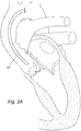
- FIGS. 2A-E A non-limiting example of a method according to the present disclosure is shown in FIGS. 2A-E .
- standard steps may be performed, including induction of anesthesia (local or general), sterile preparation and other necessary and standard steps in a transcatheter and percutaneous operation (for example, incising and/or pre-closing an artery, threading and/or removing a guidewire, and inserting and/or withdrawing a catheter).
- FIG. 2A illustrates an outer sheath 102 that has been maneuvered to reach the sinotubular junction of a subject via transfemoral, transaxillary/subclavian, or transaorticroute. Some routine steps are not shown or described here.
- a guidewire may be mounted to the outer sheath's distal end to guide the outer sheath through the subject's vasculature system.
- a catheter 101 may be inserted into the outer sheath 102.
- the outer sheath 102 encloses the distal portion of the catheter 101, the three distal branches 105 are flattened and become relatively straight inside the outer sheath 102.
- FIG. 2B illustrates the catheter 101 advanced to the distal end of the outer sheath 102. ( FIG. 2B ).
- catheter 101 may be further advanced, so that the distal end of the catheter 101 may extend from the outer sheath 102 exposing the distal branches 105 so they are no longer restrained by the sheath 102.
- the cross-sectional diameter of the tips or pigtails may be equal or slightly larger than the aortic space near the aortic valve. This will allow the tips to naturally orient the catheter into position and center the lumen in the valve. The tips can then be brought to just touching the valve or base of the valve leaflets, and also touching the sidewalls of the aortic valve and space. In other examples, the tips of the distal branches 105 may naturally fall into depressions or wells formed by the flat portion and/or base of each leaflet as illustrated in FIG. 2C . This will allow a physician to appropriately navigate the catheter 101 into position using tactile feedback from the aortic valve.
- each of the three digital branches 105 there are one or more side openings 108.
- a contrast dye may then be injected into the peripheral lumen inlet 104, through the peripheral lumen, out of the side openings 108 on the three distal branches 105, and directly to each of the three aortic leaflets ( FIG. 2D ). Then, once the dye has been injected, the aortic valve complex may be imaged using standard imaging technologies and with the aid of the contrast dye.
- each of the three distal branches 105 engages (e.g. closely abuts, touches or comes within close proximity) one of the three aortic leaflets
- a contrast dye can be directly injected into each aortic leaflet to minimize the injection frequency and amount.
- the three distal branches 105 may be configured to be equally spaced from one another on a radial plane and aligned with the three aortic leaflets, a clear visualization of a co-axial radiographic projection of the aortic valve complex can be achieved to guide a user to best orientate and implant a TAVR device (e.g., a replacement heart valve).
- a TAVR procedure may be performed before, during, or after imaging the aortic valve complex.
- the distal end of the catheter is then centered with respect to a cross sectional plane of the aortic valve complex.
- the central lumen of the catheter 101 is also co-axially aligned with the aortic valve orifice, and thus another instrument 201 (e.g., a guidewire, a catheter, and/or a pressure sensor) can be passed through the central lumen through the aortic valve orifice, in order to cross the aortic valve retrogradely in a more efficient manner.
- another instrument 201 e.g., a guidewire, a catheter, and/or a pressure sensor
- an instrument 201 (for example, a guidewire) may be inserted into the central lumen inlet 103, through the central lumen, out of the distal opening of the central lumen, further across the aortic valve orifice and into the left ventricle.
- heparinization and that the artery incision is closed either by manual compression, suture-mediated pre-closure or surgical closure.
- the procedure may be performed by local anesthesia with conscious sedation or general anesthesia, in which case the patient is generally woken up immediately after the procedure.
- Heparinization may be reversed at the end of the procedure by administration of protamine.
- Heparin intolerant individuals may be anticoagulated during the procedure using direct thrombin inhibitors.
- FIGS. 3A-E Another non-limiting example of the method is shown in FIGS. 3A-E .
- a caregiver may perform sterile preparation and other necessary and standard steps in a transcatheter and percutaneous operation (for example, incising and/or pre-closing an artery, threading and/or removing a guidewire, and inserting and/or withdrawing a catheter).
- an outer sheath 102 may be maneuvered to reach the sinotubular junction of a subject via transfemoral, transaxillary/subclavian, or transaortic route.
- a guidewire may be mounted to the outer sheath's distal end to guide the outer sheath through the subject's vasculature system.
- a catheter 101 may then be inserted into the outer sheath 102 and advanced to the distal end of the outer sheath 102.
- the three distal branches 105 are relatively straighten inside the outer sheath 102. Then, once the distal end of the catheter 101 is advanced out of the outer sheath 102 allowing the distal branches 105 to fan out into a position so each tip is equally spaced from each of the other two tips.
- the three distal branches 105 curl into a pigtail or J form. Then, as illustrated in FIG. 3C , the catheter 101 and pigtails may be navigated to engage (e.g., touch, come within close proximity, or slide into a depression formed by each leaflet) the three aortic leaflets in the aortic valve complex.
- a radiographic marker e.g., a radiopaque or radiodense marker.
- the aortic valve complex may be imaged with the aid of the radiographic markers.
- a contrast dye may be used for imaging the aortic valve complex.
- the three distal branches 105 may also have side openings 109 at or near their distal ends ( FIG. 4C ), and a contrast dye is injected into the peripheral lumen inlet 104, through the peripheral lumen, out of the side openings 109 on the three distal branches 105, and directly to each of the three aortic leaflets to aid imaging.
- a clear visualization of a co-axial radiographic projection of the aortic valve complex can be achieved to guide a user to best orientate and implant a TAVR device (e.g., a replacement heart valve).
- a TAVR procedure may be performed before, during, or after imaging the aortic valve complex.
- there may be other numbers of distal branches For example, there may be six distal branches, where pairs of distal branches are equally spaced for one another.
- the central lumen is also co-axially aligned with the aortic valve orifice
- another instrument 201 e.g., a guidewire, a catheter, and/or a pressure sensor
- An instrument 201 may be inserted into the central lumen inlet 103, through the central lumen, out of the distal opening of the central lumen, further across the aortic valve orifice and into the left ventricle ( FIG. 3D ).
- heparinization and that the artery incision is closed either by manual compression, suture-mediated pre-closure or surgical closure.
- the procedure may be performed by local anesthesia with conscious sedation or general anesthesia, in which case the patient is generally woken up immediately after the procedure.
- Heparinization may be reversed at the end of the procedure by administration of protamine.
- Heparin intolerant individuals may be anticoagulated during the procedure using direct thrombin inhibitors.
- FIGS. 4A - 4C illustrate different examples of the distal branches 105 of a catheter 101 as disclosed herein.
- FIG. 4A discloses a distal branch 105 that includes side openings 108 that are equally spaced around a loop of distal branch 105.
- FIG. 4B illustrates a distal branch 105 that includes a radiographic marker 109.
- FIG. 4C illustrates a distal branch 105 that includes a radiographic marker 109 and side openings 108.
- the side openings 108 and radiographic markers 109 may be various sizes, shapes and orientations, and may be distributed in different patterns and spatial orientations along the distal branches 105. Accordingly, FIGS. 4A - 4B only provide examples of potential configurations.
- FIG. 5 depicts a longitudinal cross sectional view of an embodiment of a catheter ( 501 ), an outer sheath covering the catheter ( 502 ), a wall of the catheter ( 503 ), an inlet ( 504 ), and three distal branches of the catheter ( 505 ).
- Panel A-A is a cross-section view of the device at its proximal end.
- Panel B-B is a cross-section view of the proximal portion of the device.
- Panel C-C is a cross-section view of the center portion of the device.
- Panel D-D is a cross-section view of the distal portion of the device.
- Panel E-E is a cross-section view of the three distal branches 505 on the distal portion of the device.
- the wall ( 503 ) forms one tube at the center portion and forms three distal branches ( 505 ) at the distal portion. Accordingly, the lumen of the tube branches into three lumen branches inside the two, three, four or more distal branches. At or near its distal end, the distal branch can comprise one or more side openings, one radiographic marker, or both (see FIGs. 4A-C ).
- the catheter 501 does not include an interior wall or separate lumens. Rather, one single lumen is utilized, for example, to inject contrast dye that may exist the side openings 108. This catheter accordingly may have a simplified construction relative to examples with multiple lumens.
- the device may include: a catheter comprising an interior wall and an exterior wall, wherein the catheter has a proximal portion, a distal portion, and a center portion between the proximal portion and the distal portion.
- the interior wall forms a central lumen along the longitudinal axis of the catheter.
- the interior wall and the exterior wall form a peripheral lumen around the central lumen along the longitudinal axis of the catheter.
- the interior wall and the exterior wall form two, three, four or more distal branches at the distal portion of the catheter, and the peripheral lumen branches into two, three, four or more peripheral lumen branches inside the two, three, four or more distal branches.
- each of the two, three, four or more distal branches comprises one or more side openings at or near the distal end of the distal branch. In various examples, each of the two, three, four or more distal branches comprises one radiographic marker at or near the distal end of the distal branch.
- the distal branches serve as radiographic markers themselves.
- the three radiographic markers denote a triangle disposed on a plane that is perpendicular and co-axial to the longitudinal axis of the device.
- the interior wall and the exterior wall are not necessarily two separate components with a defined boundary. Because their surfaces are continuous from each other from a topological point of view, the interior wall and the exterior wall may be two relative areas without a defined boundary on one integral component. For example, it is contemplated that a raw material may be molded into a catheter, in which the two walls are made simultaneously and together as one piece. Of course, the interior wall and the exterior wall may be two separate components with a defined boundary. For example, it is contemplated that the two walls are made separately first and then connected with a defined boundary to produce a catheter. However, the two walls may be made separately first and then fused to produce a catheter, in which a defined boundary between the two walls is eliminated after fusion.
- the length of the catheter may be but is not limited to any one or more of about 90-300cm, 50-90cm, 100-150cm, 150-200cm, 200-250cm, 250-300cm or 300-350cm.
- the length of the outer sheath may be but is not limited to any one or more of about 80-290cm, 50-100cm, 100-150cm, 150-200cm, 200-250cm, or 250-300cm.
- the diameter of the outer sheath may be but is not limited to any one or more of about 5-24Fr, 4-10Fr, 10-15Fr, 15-20Fr, 20-25Fr, 25-30Fr or 30-35Fr.
- the diameter of the tubular interior wall may be but is not limited to any one or more of about 1-6 Fr, 1-2Fr, 2-3Fr, 3-4Fr, 4-5Fr, 5-6Fr, 1-3Fr, 4-6Fr, 6-8Fr or 8-10Fr.
- the diameter of the tubular exterior wall may be but is not limited to any one or more of about 2-8Fr, 1-6Fr, 1-2Fr, 2-3Fr, 3-4Fr, 4-5Fr, 5-6Fr, 1-3Fr, 4-6Fr, 6-8Fr or 8-10Fr.
- the diameter of the two, three, four or more distal branches may be but is not limited to any one or more of about 1-6Fr, 1-2Fr, 2-3Fr, 3-4Fr, 4-5Fr, 5-6Fr, 1-3Fr, 4-6Fr, 6-8Fr or 8-10Fr.
- the interior wall forms a first inlet of the central lumen at the proximal portion of the catheter.
- the exterior wall forms a second inlet of the peripheral lumen at the proximal portion of the catheter.
- the two, three, four or more distal branches are pigtail-shaped or J-shaped. In various examples, the two, three, four or more distal branches are equally spaced from one another on a radial plane perpendicular to the longitudinal axis of the catheter.
- the device further comprises an outer sheath enclosing the catheter, wherein the two, three, four or more distal branches are straightened when the outer sheath encloses the distal portion of the catheter, and wherein the two, three, four or more distal branches are pigtail-shaped or J-shaped when the outer sheath does not enclose the distal portion of the catheter.
- the outer sheath further comprises a shaft, hook, ring, loop, or nose on its distal end for mounting a guidewire.
- the device further comprises an instrument, wherein the instrument is inserted into the central lumen.
- the instrument include but are not limited to a delivery system for BAV or TAVR, tube, sheath, guidewire, catheter, balloon, stent, needle, and pressure sensor.
- the device further comprises a tube, wherein the tube is inserted into the central lumen and can be advanced or retracted independently.
- the tube may be advanced over a guidewire to cross a valve or stenosis independent from the other components of the device.
- the central lumen of the catheter is relatively large (8-24 Fr) and acts as a long sheath for a balloon aortic valvuloplasty (BAV) balloon or TAVR delivery system.
- BAV balloon aortic valvuloplasty
- each of the two, three, four or more distal branches engages one heart valve leaflet.
- the central lumen is co-axially aligned with a heart valve orifice.
- the device may include a catheter comprising a wall, wherein the catheter has a proximal portion, a distal portion, and a center portion between the proximal portion and the distal portion.
- the wall forms one tube along the longitudinal axis of the catheter at the center portion and forms two, three, four or more distal branches at the distal portion.
- the lumen of the tube branches into two, three, four or more lumen branches inside the two, three, four or more distal branches.
- each of the two, three, four or more distal branches comprises one or more side openings at or near the distal end of the distal branch.
- each of the two, three, four or more distal branches comprises one radiographic marker at or near the distal end of the distal branch.
- the wall forms an inlet of the tube at the proximal portion of the catheter.
- the two, three, four or more distal branches are pigtail-shaped or J-shaped.
- the two, three, four or more distal branches are equally spaced from one another on a radial plane perpendicular to the longitudinal axis of the catheter.
- the device further comprises an outer sheath enclosing the catheter, wherein the two, three, four or more distal branches are straightened when the outer sheath encloses the distal portion of the catheter, and wherein the two, three, four or more distal branches are pigtail-shaped or J-shaped when the outer sheath does not enclose the distal portion of the catheter.
- the device further comprises a contrast dye, wherein the contrast dye is injected into the tube.
- each of the two, three, four or more distal branches engages one heart valve leaflet.
- the number of distal branches corresponds to the number of leaflets in a native valve to be imaged and/or treated.
- a device having two distal branches would be employed.
- a device having two rather than three distal branches is employed in correspondence to the two-leaflet structure of the native aortic valve.
- a method for imaging an aortic valve complex may include the following steps: (1) providing an outer sheath; (2) maneuvering the outer sheath to reach the sinotubular junction or aortic root, just above the aortic valve, of a subject; (3) providing a device comprising: a catheter comprising an interior wall and an exterior wall, wherein the catheter has a proximal portion, a distal portion, and a center portion between the proximal portion and the distal portion, wherein the interior wall forms a central lumen along the longitudinal axis of the catheter, wherein the interior wall and the exterior wall form a peripheral lumen around the central lumen along the longitudinal axis of the catheter, wherein the interior wall and the exterior wall form two, three, four or more distal branches at the distal portion of the catheter, wherein the peripheral lumen branches into two, three, four or more peripheral lumen branches inside the two, three, four or more distal branches, and wherein each of the two, three, four or more distal branches, and wherein each
- a method for imaging an aortic valve complex may include the following steps: (1) providing an outer sheath; (2) maneuvering the outer sheath to reach the sinotubular junction of a subject or aortic root, just above the aortic valve; (3) providing a device comprising: a catheter comprising an interior wall and an exterior wall, wherein the catheter has a proximal portion, a distal portion, and a center portion between the proximal portion and the distal portion, wherein the interior wall forms a central lumen along the longitudinal axis of the catheter, wherein the interior wall and the exterior wall form a peripheral lumen around the central lumen along the longitudinal axis of the catheter, wherein the interior wall and the exterior wall form two, three, four or more distal branches at the distal portion of the catheter, wherein the peripheral lumen branches into two, three, four or more peripheral lumen branches inside the two, three, four or more distal branches, and wherein each of the two, three, four or more distal
- a method for imaging an aortic valve complex may include the following steps: (1) providing an outer sheath; (2) maneuvering the outer sheath to reach the sinotubular junction or aortic root, just above the aortic valve, of a subject; (3) providing a device, comprising: a catheter comprising a wall, wherein the catheter has a proximal portion, a distal portion, and a center portion between the proximal portion and the distal portion, wherein the wall forms one tube along the longitudinal axis of the catheter at the center portion and forms two, three, four or more distal branches at the distal portion, wherein the lumen of the tube branches into two, three, four or more lumen branches inside the two, three, four or more distal branches; (4) inserting the device into the outer sheath, wherein the two, three, four or more distal branches are straightened inside the outer sheath; (5) advancing the device out of the outer sheath, wherein the two, three, four
- the device can be inserted into the outer sheath first and then the device and the outer sheath can be maneuvered as a whole through the subject's vasculature system to reach the sinotubular junction.
- transfemoral, transaxillary/subclavian or transaortic access routes are used for maneuvering the outer sheath to reach the sinotubular junction of the subject.
- the aortic valve complex is imaged with X-ray, fluoroscopy, CT, ultrasound (intravascular or echocardiography) or MRI.
- the image device detects the dye evacuated from the side openings and/or detects the radiographic marker impregnated in the distal arms.
- the method further comprises inserting an instrument into the central lumen and advancing the instrument through the aortic valve orifice into the left ventricle.
- the instrument include but are not limited to tube, sheath, guidewire, catheter, balloon, stent, needle, and pressure sensor.
- the method further comprises inserting a BAV or TAVR delivery device into the central lumen and delivering a BAV or TAVR device to the aortic valve.
- the method further comprises performing a BAV or TAVR procedure.
- the BAV or TAVR procedure may be performed before, during, or after imaging the aortic valve complex.
- TAVR is a known surgical procedure
- additional steps include, but are not limited to, anesthesia, sterilization, heparinization, accessing the patient's heart via various routes such as femoral, transseptal, transaortic and transapical approaches, ventricular pacing, stitching of the access site or percutaneous femoral closure.
- femoral, transseptal, transaortic and transapical approaches such as femoral, transseptal, transaortic and transapical approaches, ventricular pacing, stitching of the access site or percutaneous femoral closure.
- Ye et al. Transapical aortic valve implantation in humans . Ye J, Cheung A, Lichtenstein SV, Carere RG, Thompson CR, Pasupati S, Webb JG. J Thorac Cardiovasc Surg.
- Treatment and “treating,” as used herein refer to both therapeutic treatment and prophylactic or preventative measures, wherein the object is to prevent or slow down (lessen) the targeted pathologic condition, prevent the pathologic condition, pursue or obtain beneficial results, or lower the chances of the individual developing the condition even if the treatment is ultimately unsuccessful.
- Those in need of treatment include those already with the condition as well as those prone to have the condition or those in whom the condition is to be prevented.
- the pathologic condition is aortic stenosis or aortic regurgitation, mitral stenosis or mitral regurgitation, tricuspid stenosis or tricuspid regurgitation, pulmonic stenosis or pulmonic regurgitation, any vessel stenosis that requires a balloon or stent therapy, any aneurysmal vessel that requires a stent therapy, any vascular sac that requires a vascular closure, including but not limited to the left atrial appendage.
- the number of distal branches is configured to correspond to the number of leaflets in a native valve of interest. For instance, when the valve of interest is the mitral valve, which has two leaflets, a device having correspondingly two distal branches would be employed.
- “Beneficial results” may include, but are in no way limited to, lessening or alleviating the severity of the disease condition, preventing the disease condition from worsening, curing the disease condition, preventing the disease condition from developing, lowering the chances of a patient developing the disease condition and prolonging a patient's life or life expectancy.
- the disease condition is aortic stenosis or aortic regurgitation, mitral stenosis or mitral regurgitation, tricuspid stenosis or tricuspid regurgitation, pulmonic stenosis or pulmonic regurgitation, any vessel stenosis that requires a balloon or stent therapy, any aneurysmal vessel that requires a stent therapy, any vascular sac that requires a vascular closure, including but not limited to the left atrial appendage.
- the number of distal branches is configured to correspond to the number of leaflets in a native valve of interest. For instance, when the valve of interest is the mitral valve, which has two leaflets, a device having correspondingly two distal branches would be employed.
- the devices, systems and methods described herein are configured for humans.
- One of skill in the art would readily appreciate that the devices, systems and methods described herein could be customized for use in almost any mammal in which a heart valve may be replaced.
- mammal refers to any member of the class Mammalia, including but not limited to, humans, domestic animals, farm animals, zoo animals, sport animals, pet animals such as dogs, cats, guinea pigs, rabbits, rats, mice, horses, cattle, cows; primates such as apes, monkeys, orangutans, and chimpanzees; canids such as dogs and wolves; felids such as cats, lions, and tigers; equids such as horses, donkeys, and zebras; food animals such as cows, pigs, and sheep; ungulates such as deer and giraffes; rodents such as mice, rats, hamsters and guinea pigs; and so on.
- the mammal is a human subject. The term does not denote a particular age or sex. Thus, adult and newborn subjects, as well as fetuses, whether male or female, are intended to
- a replacement heart valve is a prosthetic valve or a bioprosthetic valve
- a prosthetic valve is made of purely artificial or non-biological materials
- a bioprosthetic valve is made of animal tissues alone or in combination with artificial or non-biological materials.
- Materials which may be used to construct a replacement heart valve are well known in the art, for example as described in U.S. Publication No. US2011/0319989 .
- a replacement heart valve is self-expandable or balloon expandable.
- self-expandable valves include, but are not limited to, MEDTRONIC COREVALVE, which is constructed with a nitinol self-expanding valve stent frame and porcine pericardial leaflets.
- balloon-expandable valves include, but are not limited to, EDWARDS SAPIEN XT VALVE, which is constructed with a cobalt-chromium balloon-expandable valve stent frame and bovine pericardial leaflets.
- the appropriate guide wires, sheaths and catheters for use with the devices, systems and methods described herein will be apparent to a person of skill in the art, for example, as described in Ye et al. (Transapical aortic valve implantation in humans. Ye J, Cheung A, Lichtenstein SV, Carere RG, Thompson CR, Pasupati S, Webb JG. J Thorac Cardiovasc Surg. 2006 May; 131(5): 1194-6 ), Lichtenstein et al. ( Transapical transcatheter aortic valve implantation in humans: initial clinical experience. Lichtenstein SV, Cheung A, Ye J, Thompson CR, Carere RG, Pasupati S, Webb JG. Circulation.
Landscapes
- Health & Medical Sciences (AREA)
- Life Sciences & Earth Sciences (AREA)
- Engineering & Computer Science (AREA)
- Biomedical Technology (AREA)
- Heart & Thoracic Surgery (AREA)
- Animal Behavior & Ethology (AREA)
- General Health & Medical Sciences (AREA)
- Public Health (AREA)
- Veterinary Medicine (AREA)
- Biophysics (AREA)
- Medical Informatics (AREA)
- Physics & Mathematics (AREA)
- Pathology (AREA)
- Molecular Biology (AREA)
- Surgery (AREA)
- Nuclear Medicine, Radiotherapy & Molecular Imaging (AREA)
- Hematology (AREA)
- Cardiology (AREA)
- Radiology & Medical Imaging (AREA)
- Anesthesiology (AREA)
- Pulmonology (AREA)
- High Energy & Nuclear Physics (AREA)
- Oral & Maxillofacial Surgery (AREA)
- Optics & Photonics (AREA)
- Vascular Medicine (AREA)
- Transplantation (AREA)
- Dentistry (AREA)
- Theoretical Computer Science (AREA)
- Apparatus For Radiation Diagnosis (AREA)
- Prostheses (AREA)
- Infusion, Injection, And Reservoir Apparatuses (AREA)
Claims (14)
- Dispositif comprenant :un cathéter (101) comprenant une paroi intérieure (106) et une paroi extérieure (107),dans lequel le cathéter (101) a une partie proximale, une partie distale et une partie centrale entre la partie proximale et la partie distale,dans lequel la paroi intérieure (106) forme une lumière centrale le long de l'axe longitudinal du cathéter (101),dans lequel la paroi intérieure (106) et la paroi extérieure (107) forment une lumière périphérique autour de la lumière centrale le long de l'axe longitudinal du cathéter (101),dans lequel la paroi intérieure (106) et la paroi extérieure (107) forment au moins deux branches distales (105) au niveau de la partie distale du cathéter (101), etdans lequel la lumière périphérique se ramifie en au moins deux branches de lumière périphérique à l'intérieur des au moins deux branches distales (105) ;caractérisé en ce queles au moins deux branches distales (105) sont en forme de queue de cochon ou en forme de J.
- Dispositif selon la revendication 1, dans lequel chacune des au moins deux branches distales (105) comprend une ou plusieurs ouvertures latérales (108) au niveau ou à proximité de l'extrémité distale de la branche distale (105) .
- Dispositif selon la revendication 1, dans lequel chacune des au moins deux branches distales (105) comprend un marqueur radiographique (109) au niveau ou à proximité de l'extrémité distale de la branche distale (105).
- Dispositif selon la revendication 1, dans lequel la paroi intérieure (106) forme une première entrée (103) de la lumière centrale au niveau de la partie proximale du cathéter (101).
- Dispositif selon la revendication 1, dans lequel la paroi extérieure (107) forme une seconde entrée (104) de la lumière périphérique au niveau de la partie proximale du cathéter (101).
- Dispositif selon la revendication 1, dans lequel les au moins deux branches distales (105) peuvent être avancées indépendamment par-dessus un fil central, ou sans celui-ci.
- Dispositif selon la revendication 1, dans lequel les au moins deux branches distales (105) ont des pointes arrondies.
- Dispositif selon la revendication 1, dans lequel les au moins deux branches distales (105) comprennent trois branches distales (105) qui sont configurées pour être équidistantes les unes des autres sur un plan radial perpendiculaire à l'axe longitudinal du cathéter (101) lorsqu'il n'est pas physiquement retenu par une gaine (102) ou un autre dispositif.
- Dispositif selon la revendication 1, comprenant en outre une gaine extérieure (102) renfermant le cathéter (101), dans lequel les au moins deux branches distales (105) sont étirées lorsque la gaine extérieure (102) renferme la partie distale du cathéter (101), et dans lequel les au moins deux branches distales (105) sont en forme de queue de cochon ou en forme de J lorsque la gaine extérieure (102) ne renferme pas la partie distale du cathéter (101).
- Dispositif selon la revendication 1, comprenant en outre un colorant ou médicament de contraste, dans lequel le colorant ou médicament de contraste est injecté dans la lumière périphérique.
- Dispositif selon la revendication 1, comprenant en outre un instrument (201), dans lequel l'instrument (201) est inséré dans la lumière centrale.
- Dispositif selon la revendication 1, comprenant en outre un tube, dans lequel le tube est inséré dans la lumière centrale et peut être avancé ou rétracté indépendamment.
- Dispositif selon la revendication 1, dans lequel chacune des au moins deux branches distales (105) est adaptée pour venir en prise avec un feuillet de valvule cardiaque ou chacun d'un vaisseau, d'une chambre ou d'une cavité différent(e).
- Dispositif selon la revendication 1, dans lequel la lumière centrale est alignée de manière coaxiale avec un orifice de valvule cardiaque.
Applications Claiming Priority (2)
| Application Number | Priority Date | Filing Date | Title |
|---|---|---|---|
| US201461934250P | 2014-01-31 | 2014-01-31 | |
| PCT/US2015/013956 WO2015117025A1 (fr) | 2014-01-31 | 2015-01-30 | Queue de cochon pour imagerie et alignement complexes valvulaires aortiques optimaux |
Publications (3)
| Publication Number | Publication Date |
|---|---|
| EP3099345A1 EP3099345A1 (fr) | 2016-12-07 |
| EP3099345A4 EP3099345A4 (fr) | 2017-09-27 |
| EP3099345B1 true EP3099345B1 (fr) | 2018-10-10 |
Family
ID=53757789
Family Applications (1)
| Application Number | Title | Priority Date | Filing Date |
|---|---|---|---|
| EP15743048.9A Active EP3099345B1 (fr) | 2014-01-31 | 2015-01-30 | Queue de cochon pour imagerie et alignement complexes valvulaires aortiques optimaux |
Country Status (4)
| Country | Link |
|---|---|
| US (1) | US10507301B2 (fr) |
| EP (1) | EP3099345B1 (fr) |
| CN (1) | CN105744969B (fr) |
| WO (1) | WO2015117025A1 (fr) |
Cited By (15)
| Publication number | Priority date | Publication date | Assignee | Title |
|---|---|---|---|---|
| US10856984B2 (en) | 2017-08-25 | 2020-12-08 | Neovasc Tiara Inc. | Sequentially deployed transcatheter mitral valve prosthesis |
| US10940001B2 (en) | 2012-05-30 | 2021-03-09 | Neovasc Tiara Inc. | Methods and apparatus for loading a prosthesis onto a delivery system |
| US11311376B2 (en) | 2019-06-20 | 2022-04-26 | Neovase Tiara Inc. | Low profile prosthetic mitral valve |
| US11357622B2 (en) | 2016-01-29 | 2022-06-14 | Neovase Tiara Inc. | Prosthetic valve for avoiding obstruction of outflow |
| US11389291B2 (en) | 2013-04-04 | 2022-07-19 | Neovase Tiara Inc. | Methods and apparatus for delivering a prosthetic valve to a beating heart |
| US11413139B2 (en) | 2011-11-23 | 2022-08-16 | Neovasc Tiara Inc. | Sequentially deployed transcatheter mitral valve prosthesis |
| US11419720B2 (en) | 2010-05-05 | 2022-08-23 | Neovasc Tiara Inc. | Transcatheter mitral valve prosthesis |
| US11464631B2 (en) | 2016-11-21 | 2022-10-11 | Neovasc Tiara Inc. | Methods and systems for rapid retraction of a transcatheter heart valve delivery system |
| US11491006B2 (en) | 2019-04-10 | 2022-11-08 | Neovasc Tiara Inc. | Prosthetic valve with natural blood flow |
| US11497602B2 (en) | 2012-02-14 | 2022-11-15 | Neovasc Tiara Inc. | Methods and apparatus for engaging a valve prosthesis with tissue |
| US11602429B2 (en) | 2019-04-01 | 2023-03-14 | Neovasc Tiara Inc. | Controllably deployable prosthetic valve |
| US11737872B2 (en) | 2018-11-08 | 2023-08-29 | Neovasc Tiara Inc. | Ventricular deployment of a transcatheter mitral valve prosthesis |
| US11779742B2 (en) | 2019-05-20 | 2023-10-10 | Neovasc Tiara Inc. | Introducer with hemostasis mechanism |
| US11998447B2 (en) | 2019-03-08 | 2024-06-04 | Neovasc Tiara Inc. | Retrievable prosthesis delivery system |
| US12109111B2 (en) | 2015-12-15 | 2024-10-08 | Neovasc Tiara Inc. | Transseptal delivery system |
Families Citing this family (35)
| Publication number | Priority date | Publication date | Assignee | Title |
|---|---|---|---|---|
| US10226333B2 (en) | 2013-10-15 | 2019-03-12 | Cedars-Sinai Medical Center | Anatomically-orientated and self-positioning transcatheter mitral valve |
| WO2015057995A2 (fr) | 2013-10-16 | 2015-04-23 | Cedars-Sinai Medical Center | Démontage modulaire de dispositifs de remplacement de valvule transcathéter et utilisations de ceux-ci |
| EP3057522B1 (fr) | 2013-10-17 | 2019-10-09 | Cedars-Sinai Medical Center | Dispositif pour traiter par voie percutanée l'embolisation de valvule cardiaque |
| CN105764447A (zh) | 2013-12-11 | 2016-07-13 | 雪松-西奈医学中心 | 用于在双孔二尖瓣中经导管二尖瓣置换的方法、装置和系统 |
| EP3099345B1 (fr) | 2014-01-31 | 2018-10-10 | Cedars-Sinai Medical Center | Queue de cochon pour imagerie et alignement complexes valvulaires aortiques optimaux |
| EP3782675A1 (fr) * | 2014-12-19 | 2021-02-24 | Hospital for Special Surgery | Système de perfusion multi-cathéter et procédé associé |
| WO2016145250A1 (fr) | 2015-03-12 | 2016-09-15 | Cedars-Sinai Medical Center | Dispositifs, systèmes et procédés pour optimiser l'orientation annulaire de soupapes transcathéter |
| ES2823205T3 (es) | 2016-03-22 | 2021-05-06 | Terumo Corp | Cuerpo alargado para uso médico |
| GB2556021B (en) * | 2016-07-11 | 2022-11-23 | Ganapathy Ramesh | Medical apparatus |
| WO2018091895A1 (fr) * | 2016-11-16 | 2018-05-24 | Persica Pharmaceuticals Ltd. | Formulations antibiotiques pour douleurs lombaires |
| CA3081449A1 (fr) | 2017-11-16 | 2019-05-23 | Persica Pharmaceuticals Ltd. | Formulations de linezolide |
| CN108403249A (zh) * | 2018-01-24 | 2018-08-17 | 四川省人民医院 | 一种主动脉瓣关闭不全动物模型制作装置 |
| WO2019195860A2 (fr) | 2018-04-04 | 2019-10-10 | Vdyne, Llc | Dispositifs et procédés d'ancrage d'une valvule cardiaque transcathéter |
| US11534574B2 (en) * | 2018-06-21 | 2022-12-27 | Apparent Llc | Annulus plane catheter |
| JP7215812B2 (ja) * | 2018-09-11 | 2023-01-31 | ザ クーパー ヘルス システム | 体腔灌注および排液システムおよび方法 |
| US11278437B2 (en) | 2018-12-08 | 2022-03-22 | Vdyne, Inc. | Compression capable annular frames for side delivery of transcatheter heart valve replacement |
| US11344413B2 (en) | 2018-09-20 | 2022-05-31 | Vdyne, Inc. | Transcatheter deliverable prosthetic heart valves and methods of delivery |
| US10321995B1 (en) | 2018-09-20 | 2019-06-18 | Vdyne, Llc | Orthogonally delivered transcatheter heart valve replacement |
| US10595994B1 (en) | 2018-09-20 | 2020-03-24 | Vdyne, Llc | Side-delivered transcatheter heart valve replacement |
| US11071627B2 (en) | 2018-10-18 | 2021-07-27 | Vdyne, Inc. | Orthogonally delivered transcatheter heart valve frame for valve in valve prosthesis |
| US11109969B2 (en) | 2018-10-22 | 2021-09-07 | Vdyne, Inc. | Guidewire delivery of transcatheter heart valve |
| US11253359B2 (en) | 2018-12-20 | 2022-02-22 | Vdyne, Inc. | Proximal tab for side-delivered transcatheter heart valves and methods of delivery |
| EP3677223A1 (fr) * | 2019-01-04 | 2020-07-08 | Ivan Casserley | Dispositif pour déterminer le plan d'un anneau de valvule cardiaque |
| US11185409B2 (en) | 2019-01-26 | 2021-11-30 | Vdyne, Inc. | Collapsible inner flow control component for side-delivered transcatheter heart valve prosthesis |
| US11273032B2 (en) | 2019-01-26 | 2022-03-15 | Vdyne, Inc. | Collapsible inner flow control component for side-deliverable transcatheter heart valve prosthesis |
| AU2020231221A1 (en) | 2019-03-05 | 2021-09-23 | Vdyne, Inc. | Tricuspid regurgitation control devices for orthogonal transcatheter heart valve prosthesis |
| US11173027B2 (en) | 2019-03-14 | 2021-11-16 | Vdyne, Inc. | Side-deliverable transcatheter prosthetic valves and methods for delivering and anchoring the same |
| US11076956B2 (en) | 2019-03-14 | 2021-08-03 | Vdyne, Inc. | Proximal, distal, and anterior anchoring tabs for side-delivered transcatheter mitral valve prosthesis |
| JP7529689B2 (ja) | 2019-05-04 | 2024-08-06 | ブイダイン,インコーポレイテッド | 生来の弁輪での側方送達される人工心臓弁を展開するための締め付けデバイス及び方法 |
| CA3152042A1 (fr) | 2019-08-20 | 2021-02-25 | Vdyne, Inc. | Dispositifs d'administration et de recuperation et procedes pour valvules prothetiques transcatheter a pose laterale |
| CA3152632A1 (fr) | 2019-08-26 | 2021-03-04 | Vdyne, Inc. | Valvules prothetiques transcatheter a pose laterale et procedes pour leurs pose et ancrage |
| WO2021086950A1 (fr) * | 2019-10-28 | 2021-05-06 | Khadivi Bahram | Systèmes et procédés de déploiement de valves aortiques transcathéter |
| US11234813B2 (en) | 2020-01-17 | 2022-02-01 | Vdyne, Inc. | Ventricular stability elements for side-deliverable prosthetic heart valves and methods of delivery |
| WO2022191977A1 (fr) * | 2021-03-08 | 2022-09-15 | Edwards Lifesciences Corporation | Dispositifs et systèmes de positionnement de fil-guide |
| EP4352739A2 (fr) * | 2021-06-07 | 2024-04-17 | Dasisimulations, Llc | Systèmes et procédés pour optimiser des interventions médicales à l'aide de modèles prédictifs |
Family Cites Families (104)
| Publication number | Priority date | Publication date | Assignee | Title |
|---|---|---|---|---|
| US4694838A (en) * | 1984-01-30 | 1987-09-22 | Mallinckrodt, Inc. | Loop coronary catheter |
| US4738667A (en) * | 1986-11-04 | 1988-04-19 | Galloway Niall T M | Preformed catheter assembly |
| US5964744A (en) * | 1993-01-04 | 1999-10-12 | Menlo Care, Inc. | Polymeric medical device systems having shape memory |
| US5423829A (en) | 1993-11-03 | 1995-06-13 | Target Therapeutics, Inc. | Electrolytically severable joint for endovascular embolic devices |
| AU2391795A (en) | 1994-04-22 | 1995-11-16 | Medtronic, Inc. | Stented bioprosthetic heart valve |
| US5695457A (en) * | 1994-07-28 | 1997-12-09 | Heartport, Inc. | Cardioplegia catheter system |
| EP1658808A1 (fr) | 1994-09-02 | 2006-05-24 | Volcano Corporation | Capteur de pression ultra-miniaturise et fil de guidage équipe de ce dernier |
| IL116561A0 (en) | 1994-12-30 | 1996-03-31 | Target Therapeutics Inc | Severable joint for detachable devices placed within the body |
| US6059779A (en) | 1995-04-28 | 2000-05-09 | Target Therapeutics, Inc. | Delivery catheter for electrolytically detachable implant |
| US5972019A (en) | 1996-07-25 | 1999-10-26 | Target Therapeutics, Inc. | Mechanical clot treatment device |
| US5964797A (en) | 1996-08-30 | 1999-10-12 | Target Therapeutics, Inc. | Electrolytically deployable braided vaso-occlusion device |
| US6013054A (en) | 1997-04-28 | 2000-01-11 | Advanced Cardiovascular Systems, Inc. | Multifurcated balloon catheter |
| WO1999015227A1 (fr) | 1997-09-26 | 1999-04-01 | Cardeon Corporation | Instrument de catheterisation de phase principale |
| AU9669898A (en) | 1997-09-26 | 1999-04-12 | Cardeon Corporation | Multi-function aortic catheterization and bumper instrument |
| US6146373A (en) | 1997-10-17 | 2000-11-14 | Micro Therapeutics, Inc. | Catheter system and method for injection of a liquid embolic composition and a solidification agent |
| US6086557A (en) * | 1998-10-01 | 2000-07-11 | Cardiothoracic Systems, Inc. | Bifurcated venous cannula |
| US20020169474A1 (en) | 1999-03-08 | 2002-11-14 | Microvena Corporation | Minimally invasive medical device deployment and retrieval system |
| US6217611B1 (en) | 1999-05-26 | 2001-04-17 | Sulzer Carbomedics Inc. | Modular heart valve prothesis |
| AUPR217000A0 (en) | 2000-12-19 | 2001-01-25 | Oldfield Family Holdings Pty Limited | Double lumen pigtail pressure monitoring catheter |
| US6953473B2 (en) | 2001-12-20 | 2005-10-11 | Boston Scientific Scimed, Inc. | Detachable device with electrically responsive element |
| US7118303B2 (en) | 2003-12-10 | 2006-10-10 | Zimmer Spine, Inc. | Internally disposed linear fastener system |
| US7134994B2 (en) | 2002-05-20 | 2006-11-14 | Volcano Corporation | Multipurpose host system for invasive cardiovascular diagnostic measurement acquisition and display |
| US20040002752A1 (en) | 2002-06-26 | 2004-01-01 | Scimed Life Systems, Inc. | Sacrificial anode stent system |
| DE10242444A1 (de) | 2002-09-11 | 2004-04-01 | pfm Produkte für die Medizin AG | Extraktionsvorrichtung |
| US20040172081A1 (en) | 2003-02-28 | 2004-09-02 | Dai-Yuan Wang | Intracardiac pressure guided pacemaker |
| US10219899B2 (en) | 2004-04-23 | 2019-03-05 | Medtronic 3F Therapeutics, Inc. | Cardiac valve replacement systems |
| US20050159810A1 (en) | 2004-01-15 | 2005-07-21 | Farzan Filsoufi | Devices and methods for repairing cardiac valves |
| CA2556077C (fr) | 2004-02-05 | 2012-05-01 | Children's Medical Center Corporation | Apport par catheter d'une valvule cardiaque de remplacement |
| US20050203425A1 (en) | 2004-03-10 | 2005-09-15 | Phil Langston | Coaxial dual lumen pigtail catheter |
| US20050256566A1 (en) | 2004-05-03 | 2005-11-17 | Shlomo Gabbay | Apparatus and method for improving ventricular function |
| EP1750506A4 (fr) | 2004-05-14 | 2010-03-17 | Flowmedica Inc | Administration renale locale bilaterale pour le traitement de l'insuffisance cardiaque congestive et la therapie aux peptides natriuretiques de type b |
| US8055573B2 (en) | 2004-07-15 | 2011-11-08 | Flint Hills Resources, L. P. | System method for marketing commodity products electronically |
| JP2006087630A (ja) | 2004-09-22 | 2006-04-06 | Terumo Corp | 血管内異物除去用ワイヤおよび医療器具 |
| US7340288B1 (en) | 2005-02-07 | 2008-03-04 | Pacesetter, Inc. | Trans-septal intra-cardiac lead system |
| WO2006127756A2 (fr) | 2005-05-24 | 2006-11-30 | Edwards Lifesciences Corporation | Prothese de valvule cardiaque a deploiement rapide |
| US7455689B2 (en) | 2005-08-25 | 2008-11-25 | Edwards Lifesciences Corporation | Four-leaflet stented mitral heart valve |
| WO2007081820A1 (fr) | 2006-01-09 | 2007-07-19 | Children's Medical Center Corporation | Livraison par cathéter d'une valve cardiaque de remplacement |
| US9119651B2 (en) | 2006-02-13 | 2015-09-01 | Retro Vascular, Inc. | Recanalizing occluded vessels using controlled antegrade and retrograde tracking |
| US8821561B2 (en) | 2006-02-22 | 2014-09-02 | Boston Scientific Scimed, Inc. | Marker arrangement for bifurcation catheter |
| EP2015709B1 (fr) | 2006-05-05 | 2013-01-09 | Children's Medical Center Corporation | Prothèses de valvules cardiaques par cathéter |
| US8092470B2 (en) | 2006-06-08 | 2012-01-10 | Olympus Medical Systems Corp. | Calculus crushing apparatus and medical procedure using endoscope |
| US20080021546A1 (en) | 2006-07-18 | 2008-01-24 | Tim Patz | System for deploying balloon-expandable heart valves |
| US7935144B2 (en) | 2006-10-19 | 2011-05-03 | Direct Flow Medical, Inc. | Profile reduction of valve implant |
| WO2008051554A2 (fr) | 2006-10-24 | 2008-05-02 | Beth Israel Deaconess Medical Center | Systeme percutané de valve aortique |
| WO2008091515A2 (fr) | 2007-01-19 | 2008-07-31 | Medtronic, Inc. | Dispositifs de valve cardiaque à stent et procédés de remplacement d'une valve cardiaque auriculo-ventriculaire |
| WO2008112563A1 (fr) | 2007-03-09 | 2008-09-18 | Flowmedica, Inc. | Systèmes et procédés de traitement de lésion rénale aiguë |
| US8663217B2 (en) | 2007-05-29 | 2014-03-04 | Cvdevices, Llc | Devices and systems for valve removal |
| US9814611B2 (en) | 2007-07-31 | 2017-11-14 | Edwards Lifesciences Cardiaq Llc | Actively controllable stent, stent graft, heart valve and method of controlling same |
| US8216151B2 (en) | 2007-09-25 | 2012-07-10 | Radi Medical Systems Ab | Pressure wire assembly |
| US8430927B2 (en) | 2008-04-08 | 2013-04-30 | Medtronic, Inc. | Multiple orifice implantable heart valve and methods of implantation |
| US20090276040A1 (en) | 2008-05-01 | 2009-11-05 | Edwards Lifesciences Corporation | Device and method for replacing mitral valve |
| US8323335B2 (en) | 2008-06-20 | 2012-12-04 | Edwards Lifesciences Corporation | Retaining mechanisms for prosthetic valves and methods for using |
| US20100030330A1 (en) | 2008-08-01 | 2010-02-04 | Edwards Lifesciences Corporation | Device and method for mitral valve repair |
| US7951111B2 (en) * | 2008-10-10 | 2011-05-31 | Intervalve, Inc. | Valvuloplasty catheter and methods |
| US9402720B2 (en) | 2009-01-12 | 2016-08-02 | Valve Medical Ltd. | Modular percutaneous valve structure and delivery method |
| AU2010206658A1 (en) | 2009-01-22 | 2011-08-25 | St. Jude Medical, Cardiology Division, Inc. | Magnetic docking system and method for the long term adjustment of an implantable device |
| US20100191272A1 (en) | 2009-01-23 | 2010-07-29 | Salviac Limited | Distal access embolic protection system and methods of using the same |
| US20100211094A1 (en) | 2009-02-18 | 2010-08-19 | Cook Incorporated | Umbrella distal embolic protection device |
| US8657870B2 (en) | 2009-06-26 | 2014-02-25 | Biosensors International Group, Ltd. | Implant delivery apparatus and methods with electrolytic release |
| WO2011035154A1 (fr) | 2009-09-18 | 2011-03-24 | The Regents Of The University Of California | Remplacement de valvule cardiaque prothetique endovasculaire |
| DE102009047845A1 (de) | 2009-09-30 | 2011-03-31 | Abiomed Europe Gmbh | Herzunterstützungssystem |
| US9011520B2 (en) | 2009-10-29 | 2015-04-21 | Valtech Cardio, Ltd. | Tissue anchor for annuloplasty device |
| US8449599B2 (en) | 2009-12-04 | 2013-05-28 | Edwards Lifesciences Corporation | Prosthetic valve for replacing mitral valve |
| US8408214B2 (en) | 2010-07-08 | 2013-04-02 | Benjamin Spenser | Method for implanting prosthetic valve |
| JP5848345B2 (ja) | 2010-07-09 | 2016-01-27 | ハイライフ エスエーエス | 経カテーテル式房室弁人工器官 |
| WO2012009675A2 (fr) | 2010-07-15 | 2012-01-19 | Lazarus Effect, Inc. | Système d'extraction et procédés d'utilisation associé |
| JP5970458B2 (ja) | 2010-09-01 | 2016-08-17 | ムバルブ・テクノロジーズ・リミテッド | 心臓弁支持構造体 |
| US8971993B2 (en) | 2010-11-19 | 2015-03-03 | Mediguide Ltd. | Systems and methods for navigating a surgical device |
| US9579197B2 (en) | 2010-12-15 | 2017-02-28 | Medtronic Vascular, Inc. | Systems and methods for positioning a heart valve using visual markers |
| US10111663B2 (en) | 2011-02-18 | 2018-10-30 | Ancora Heart, Inc. | Implant retrieval device |
| US9017365B2 (en) | 2011-05-02 | 2015-04-28 | Cook Medical Technologies Llc | Polarizable delivery mechanism for medical device deployment |
| US9289282B2 (en) | 2011-05-31 | 2016-03-22 | Edwards Lifesciences Corporation | System and method for treating valve insufficiency or vessel dilatation |
| EP2717759A4 (fr) | 2011-06-13 | 2014-12-10 | Angiometrix Corp | Ensembles fils-guides multifontionnels et système pour analyser des paramètres anatomiques et fonctionnels |
| EP2723272A4 (fr) | 2011-06-24 | 2015-01-28 | Inceptus Medical LLC | Système de valvules cardiaques artificielles implantables par voie percutanée, et procédés et dispositifs associés |
| US20130046376A1 (en) | 2011-06-24 | 2013-02-21 | Ali Hassan | Method and devices for flow occlusion during device exchanges |
| GB2493345A (en) | 2011-07-29 | 2013-02-06 | Mirza Kamran Baig | Capture and retrieval of foreign bodies from the vessel of a patient |
| US20130190857A1 (en) | 2011-09-09 | 2013-07-25 | Endoluminal Sciences Pty Ltd. | Means for controlled sealing of endovascular devices |
| US20140243688A1 (en) | 2011-10-28 | 2014-08-28 | Three Rivers Cardiovascular Systems Inc. | Fluid temperature and flow sensor apparatus and system for cardiovascular and other medical applications |
| WO2013067194A2 (fr) * | 2011-11-01 | 2013-05-10 | Stinis Curtiss T | Systèmes, dispositifs et procédés de positionnement de valvules sigmoïdes |
| US20140350669A1 (en) | 2011-12-01 | 2014-11-27 | The Trustees if The University of Pennsylvania | Percutaneous valve replacement devices |
| EP2620125B1 (fr) | 2012-01-24 | 2017-10-11 | Medtentia International Ltd Oy | Agencement, support en forme de boucle, prothèse valvulaire cardiaque et procédé de réparation ou de remplacement de valvule cardiaque native |
| US10172708B2 (en) | 2012-01-25 | 2019-01-08 | Boston Scientific Scimed, Inc. | Valve assembly with a bioabsorbable gasket and a replaceable valve implant |
| AU2013227235B2 (en) | 2012-02-28 | 2017-10-19 | Mvalve Technologies Ltd. | Single-ring cardiac valve support |
| US9066800B2 (en) | 2012-03-28 | 2015-06-30 | Medtronic, Inc. | Dual valve prosthesis for transcatheter valve implantation |
| US9023098B2 (en) | 2012-03-28 | 2015-05-05 | Medtronic, Inc. | Dual valve prosthesis for transcatheter valve implantation |
| US20130274618A1 (en) | 2012-04-17 | 2013-10-17 | Boston Scientific Scimed, Inc. | Guidewire system for use in transcatheter aortic valve implantation procedures |
| WO2013185138A1 (fr) * | 2012-06-08 | 2013-12-12 | Essential Medical, Llc | Cathéter bifurqué |
| US9526610B2 (en) | 2012-06-12 | 2016-12-27 | Medtronic, Inc. | Method and device for percutaneous valve annuloplasty |
| US9144663B2 (en) | 2012-10-24 | 2015-09-29 | Medtronic, Inc. | Methods and devices for repairing and/or preventing paravalvular leakage post-implantation of a valve prosthesis |
| EP2732796A1 (fr) | 2012-11-20 | 2014-05-21 | Nakostech Sarl | Système de remplacement de valve mitrale |
| US9132007B2 (en) | 2013-01-10 | 2015-09-15 | Medtronic CV Luxembourg S.a.r.l. | Anti-paravalvular leakage components for a transcatheter valve prosthesis |
| US20140200662A1 (en) | 2013-01-16 | 2014-07-17 | Mvalve Technologies Ltd. | Anchoring elements for intracardiac devices |
| US9675451B2 (en) | 2013-02-01 | 2017-06-13 | Medtronic CV Luxembourg S.a.r.l. | Anti-paravalvular leakage component for a transcatheter valve prosthesis |
| US10413401B2 (en) | 2013-02-01 | 2019-09-17 | Medtronic CV Luxembourg S.a.r.l. | Anti-paravalvular leakage component for a transcatheter valve prosthesis |
| US9456897B2 (en) | 2013-02-21 | 2016-10-04 | Medtronic, Inc. | Transcatheter valve prosthesis and a concurrently delivered sealing component |
| US8986375B2 (en) | 2013-03-12 | 2015-03-24 | Medtronic, Inc. | Anti-paravalvular leakage component for a transcatheter valve prosthesis |
| EP2967602B1 (fr) | 2013-03-15 | 2019-08-28 | Volcano Corporation | Systèmes de protection distale faisant intervenir des accessoires de pression et à ultrasons |
| US20160228013A1 (en) | 2013-10-07 | 2016-08-11 | Cedars-Sinai Medical Center | Transcatheter aortic valve implantation pressure wires and uses thereof |
| US10226333B2 (en) | 2013-10-15 | 2019-03-12 | Cedars-Sinai Medical Center | Anatomically-orientated and self-positioning transcatheter mitral valve |
| WO2015057995A2 (fr) | 2013-10-16 | 2015-04-23 | Cedars-Sinai Medical Center | Démontage modulaire de dispositifs de remplacement de valvule transcathéter et utilisations de ceux-ci |
| EP3057522B1 (fr) | 2013-10-17 | 2019-10-09 | Cedars-Sinai Medical Center | Dispositif pour traiter par voie percutanée l'embolisation de valvule cardiaque |
| CN105764447A (zh) | 2013-12-11 | 2016-07-13 | 雪松-西奈医学中心 | 用于在双孔二尖瓣中经导管二尖瓣置换的方法、装置和系统 |
| EP3099345B1 (fr) | 2014-01-31 | 2018-10-10 | Cedars-Sinai Medical Center | Queue de cochon pour imagerie et alignement complexes valvulaires aortiques optimaux |
| WO2016145250A1 (fr) | 2015-03-12 | 2016-09-15 | Cedars-Sinai Medical Center | Dispositifs, systèmes et procédés pour optimiser l'orientation annulaire de soupapes transcathéter |
-
2015
- 2015-01-30 EP EP15743048.9A patent/EP3099345B1/fr active Active
- 2015-01-30 US US15/103,690 patent/US10507301B2/en active Active
- 2015-01-30 WO PCT/US2015/013956 patent/WO2015117025A1/fr active Application Filing
- 2015-01-30 CN CN201580002673.3A patent/CN105744969B/zh active Active
Non-Patent Citations (1)
| Title |
|---|
| None * |
Cited By (21)
| Publication number | Priority date | Publication date | Assignee | Title |
|---|---|---|---|---|
| US11419720B2 (en) | 2010-05-05 | 2022-08-23 | Neovasc Tiara Inc. | Transcatheter mitral valve prosthesis |
| US12053369B2 (en) | 2011-11-23 | 2024-08-06 | Neovasc Tiara Inc. | Sequentially deployed transcatheter mitral valve prosthesis |
| US11413139B2 (en) | 2011-11-23 | 2022-08-16 | Neovasc Tiara Inc. | Sequentially deployed transcatheter mitral valve prosthesis |
| US11497602B2 (en) | 2012-02-14 | 2022-11-15 | Neovasc Tiara Inc. | Methods and apparatus for engaging a valve prosthesis with tissue |
| US10940001B2 (en) | 2012-05-30 | 2021-03-09 | Neovasc Tiara Inc. | Methods and apparatus for loading a prosthesis onto a delivery system |
| US11617650B2 (en) | 2012-05-30 | 2023-04-04 | Neovasc Tiara Inc. | Methods and apparatus for loading a prosthesis onto a delivery system |
| US11389294B2 (en) | 2012-05-30 | 2022-07-19 | Neovasc Tiara Inc. | Methods and apparatus for loading a prosthesis onto a delivery system |
| US11389291B2 (en) | 2013-04-04 | 2022-07-19 | Neovase Tiara Inc. | Methods and apparatus for delivering a prosthetic valve to a beating heart |
| US12109111B2 (en) | 2015-12-15 | 2024-10-08 | Neovasc Tiara Inc. | Transseptal delivery system |
| US11357622B2 (en) | 2016-01-29 | 2022-06-14 | Neovase Tiara Inc. | Prosthetic valve for avoiding obstruction of outflow |
| US11464631B2 (en) | 2016-11-21 | 2022-10-11 | Neovasc Tiara Inc. | Methods and systems for rapid retraction of a transcatheter heart valve delivery system |
| US11793640B2 (en) | 2017-08-25 | 2023-10-24 | Neovasc Tiara Inc. | Sequentially deployed transcatheter mitral valve prosthesis |
| US10856984B2 (en) | 2017-08-25 | 2020-12-08 | Neovasc Tiara Inc. | Sequentially deployed transcatheter mitral valve prosthesis |
| US11737872B2 (en) | 2018-11-08 | 2023-08-29 | Neovasc Tiara Inc. | Ventricular deployment of a transcatheter mitral valve prosthesis |
| US11998447B2 (en) | 2019-03-08 | 2024-06-04 | Neovasc Tiara Inc. | Retrievable prosthesis delivery system |
| US11602429B2 (en) | 2019-04-01 | 2023-03-14 | Neovasc Tiara Inc. | Controllably deployable prosthetic valve |
| US12036117B2 (en) | 2019-04-10 | 2024-07-16 | Neovasc Tiara Inc. | Prosthetic valve with natural blood flow |
| US11491006B2 (en) | 2019-04-10 | 2022-11-08 | Neovasc Tiara Inc. | Prosthetic valve with natural blood flow |
| US11779742B2 (en) | 2019-05-20 | 2023-10-10 | Neovasc Tiara Inc. | Introducer with hemostasis mechanism |
| US11931254B2 (en) | 2019-06-20 | 2024-03-19 | Neovasc Tiara Inc. | Low profile prosthetic mitral valve |
| US11311376B2 (en) | 2019-06-20 | 2022-04-26 | Neovase Tiara Inc. | Low profile prosthetic mitral valve |
Also Published As
| Publication number | Publication date |
|---|---|
| CN105744969A (zh) | 2016-07-06 |
| WO2015117025A1 (fr) | 2015-08-06 |
| US10507301B2 (en) | 2019-12-17 |
| US20160310699A1 (en) | 2016-10-27 |
| CN105744969B (zh) | 2019-12-31 |
| EP3099345A4 (fr) | 2017-09-27 |
| EP3099345A1 (fr) | 2016-12-07 |
Similar Documents
| Publication | Publication Date | Title |
|---|---|---|
| EP3099345B1 (fr) | Queue de cochon pour imagerie et alignement complexes valvulaires aortiques optimaux | |
| JP6434589B2 (ja) | 心弁置換用人工器官システム | |
| US20240173151A1 (en) | Devices and methods for coronary sinus pressure relief | |
| JP7319014B2 (ja) | 経皮システム、デバイス、および方法 | |
| JP6341211B2 (ja) | 人工心弁移植用ガイドワイヤシステムを心室内部に配置させるための装置 | |
| US10799360B2 (en) | Systems and methods for treating a regurgitant heart valve | |
| JP7002194B2 (ja) | 無縫合人工弁搬送装置およびその使用方法 | |
| US10603166B2 (en) | Delivery device having a curved shaft and a straightening member for transcatheter aortic valve implantation | |
| US9510947B2 (en) | Catheter system for introducing an expandable heart valve stent into the body of a patient | |
| US20090264859A1 (en) | Catheter Having a Selectively Expandable Distal Tip | |
| CN105682565A (zh) | 二尖瓣环扎瓣环成形术中的右心室流出道线捕捉(rwc)系统 | |
| KR20220101149A (ko) | 경도관 의료용 이식물 전달 | |
| US20090264863A1 (en) | Articulating Tip Tetherless Catheter System | |
| CN111374798B (zh) | 介入引导装置 | |
| JP2017529217A (ja) | 慢性完全閉塞を有する身体血管における再進入のためのカテーテルシステムおよび方法 | |
| US11779462B2 (en) | Conveyor and conveyor system | |
| JP2011147580A (ja) | ガイドワイヤ | |
| EP4437981A1 (fr) | Ensemble gaine concentrique pour retrait de feuillet de valvule aortique et dispositifs, systèmes et procédés associés | |
| US20210128299A1 (en) | Systems and methods for deploying transcatheter heart valves | |
| EP4389072A1 (fr) | Ensemble cathéter, système d'implant, système de pose d'implant et une méthode d'utilisation correspondante | |
| US20240325175A1 (en) | Devices and methods for coronary sinus pressure relief | |
| US20240315847A1 (en) | Surgical system for a heart valve | |
| WO2022146366A1 (fr) | Canule ecmo (oxygénation à membrane extracorporelle) veino-veineuse à flux d'entrée multiples, à flux de sortie multiples et à double lumière | |
| CN115645027A (zh) | 远端可调的导管、消融装置及消融系统 | |
| JP2024524997A (ja) | 停滞装置によるインプラント及び造影剤の送達 |
Legal Events
| Date | Code | Title | Description |
|---|---|---|---|
| PUAI | Public reference made under article 153(3) epc to a published international application that has entered the european phase |
Free format text: ORIGINAL CODE: 0009012 |
|
| STAA | Information on the status of an ep patent application or granted ep patent |
Free format text: STATUS: REQUEST FOR EXAMINATION WAS MADE |
|
| 17P | Request for examination filed |
Effective date: 20160506 |
|
| AK | Designated contracting states |
Kind code of ref document: A1 Designated state(s): AL AT BE BG CH CY CZ DE DK EE ES FI FR GB GR HR HU IE IS IT LI LT LU LV MC MK MT NL NO PL PT RO RS SE SI SK SM TR |
|
| AX | Request for extension of the european patent |
Extension state: BA ME |
|
| DAX | Request for extension of the european patent (deleted) | ||
| A4 | Supplementary search report drawn up and despatched |
Effective date: 20170824 |
|
| RIC1 | Information provided on ipc code assigned before grant |
Ipc: A61B 8/08 20060101ALI20170818BHEP Ipc: A61M 5/00 20060101ALI20170818BHEP Ipc: A61F 2/24 20060101ALI20170818BHEP Ipc: A61B 5/00 20060101ALI20170818BHEP Ipc: A61B 8/12 20060101ALI20170818BHEP Ipc: A61M 25/01 20060101ALI20170818BHEP Ipc: A61M 25/06 20060101ALI20170818BHEP Ipc: A61B 5/055 20060101ALI20170818BHEP Ipc: A61B 6/03 20060101ALI20170818BHEP Ipc: A61M 25/00 20060101ALI20170818BHEP Ipc: A61M 3/00 20060101AFI20170818BHEP Ipc: A61M 31/00 20060101ALI20170818BHEP Ipc: A61B 6/00 20060101ALI20170818BHEP |
|
| GRAP | Despatch of communication of intention to grant a patent |
Free format text: ORIGINAL CODE: EPIDOSNIGR1 |
|
| STAA | Information on the status of an ep patent application or granted ep patent |
Free format text: STATUS: GRANT OF PATENT IS INTENDED |
|
| INTG | Intention to grant announced |
Effective date: 20180426 |
|
| GRAS | Grant fee paid |
Free format text: ORIGINAL CODE: EPIDOSNIGR3 |
|
| GRAA | (expected) grant |
Free format text: ORIGINAL CODE: 0009210 |
|
| STAA | Information on the status of an ep patent application or granted ep patent |
Free format text: STATUS: THE PATENT HAS BEEN GRANTED |
|
| AK | Designated contracting states |
Kind code of ref document: B1 Designated state(s): AL AT BE BG CH CY CZ DE DK EE ES FI FR GB GR HR HU IE IS IT LI LT LU LV MC MK MT NL NO PL PT RO RS SE SI SK SM TR |
|
| REG | Reference to a national code |
Ref country code: GB Ref legal event code: FG4D |
|
| REG | Reference to a national code |
Ref country code: CH Ref legal event code: EP Ref country code: AT Ref legal event code: REF Ref document number: 1050491 Country of ref document: AT Kind code of ref document: T Effective date: 20181015 |
|
| REG | Reference to a national code |
Ref country code: CH Ref legal event code: NV Representative=s name: BOVARD AG PATENT- UND MARKENANWAELTE, CH Ref country code: IE Ref legal event code: FG4D |
|
| REG | Reference to a national code |
Ref country code: DE Ref legal event code: R096 Ref document number: 602015017895 Country of ref document: DE |
|
| REG | Reference to a national code |
Ref country code: NL Ref legal event code: MP Effective date: 20181010 |
|
| REG | Reference to a national code |
Ref country code: LT Ref legal event code: MG4D |
|
| REG | Reference to a national code |
Ref country code: AT Ref legal event code: MK05 Ref document number: 1050491 Country of ref document: AT Kind code of ref document: T Effective date: 20181010 |
|
| PG25 | Lapsed in a contracting state [announced via postgrant information from national office to epo] |
Ref country code: NL Free format text: LAPSE BECAUSE OF FAILURE TO SUBMIT A TRANSLATION OF THE DESCRIPTION OR TO PAY THE FEE WITHIN THE PRESCRIBED TIME-LIMIT Effective date: 20181010 |
|
| PG25 | Lapsed in a contracting state [announced via postgrant information from national office to epo] |
Ref country code: ES Free format text: LAPSE BECAUSE OF FAILURE TO SUBMIT A TRANSLATION OF THE DESCRIPTION OR TO PAY THE FEE WITHIN THE PRESCRIBED TIME-LIMIT Effective date: 20181010 Ref country code: LV Free format text: LAPSE BECAUSE OF FAILURE TO SUBMIT A TRANSLATION OF THE DESCRIPTION OR TO PAY THE FEE WITHIN THE PRESCRIBED TIME-LIMIT Effective date: 20181010 Ref country code: AT Free format text: LAPSE BECAUSE OF FAILURE TO SUBMIT A TRANSLATION OF THE DESCRIPTION OR TO PAY THE FEE WITHIN THE PRESCRIBED TIME-LIMIT Effective date: 20181010 Ref country code: HR Free format text: LAPSE BECAUSE OF FAILURE TO SUBMIT A TRANSLATION OF THE DESCRIPTION OR TO PAY THE FEE WITHIN THE PRESCRIBED TIME-LIMIT Effective date: 20181010 Ref country code: PL Free format text: LAPSE BECAUSE OF FAILURE TO SUBMIT A TRANSLATION OF THE DESCRIPTION OR TO PAY THE FEE WITHIN THE PRESCRIBED TIME-LIMIT Effective date: 20181010 Ref country code: LT Free format text: LAPSE BECAUSE OF FAILURE TO SUBMIT A TRANSLATION OF THE DESCRIPTION OR TO PAY THE FEE WITHIN THE PRESCRIBED TIME-LIMIT Effective date: 20181010 Ref country code: NO Free format text: LAPSE BECAUSE OF FAILURE TO SUBMIT A TRANSLATION OF THE DESCRIPTION OR TO PAY THE FEE WITHIN THE PRESCRIBED TIME-LIMIT Effective date: 20190110 Ref country code: IS Free format text: LAPSE BECAUSE OF FAILURE TO SUBMIT A TRANSLATION OF THE DESCRIPTION OR TO PAY THE FEE WITHIN THE PRESCRIBED TIME-LIMIT Effective date: 20190210 Ref country code: FI Free format text: LAPSE BECAUSE OF FAILURE TO SUBMIT A TRANSLATION OF THE DESCRIPTION OR TO PAY THE FEE WITHIN THE PRESCRIBED TIME-LIMIT Effective date: 20181010 Ref country code: BG Free format text: LAPSE BECAUSE OF FAILURE TO SUBMIT A TRANSLATION OF THE DESCRIPTION OR TO PAY THE FEE WITHIN THE PRESCRIBED TIME-LIMIT Effective date: 20190110 |
|
| PG25 | Lapsed in a contracting state [announced via postgrant information from national office to epo] |
Ref country code: GR Free format text: LAPSE BECAUSE OF FAILURE TO SUBMIT A TRANSLATION OF THE DESCRIPTION OR TO PAY THE FEE WITHIN THE PRESCRIBED TIME-LIMIT Effective date: 20190111 Ref country code: RS Free format text: LAPSE BECAUSE OF FAILURE TO SUBMIT A TRANSLATION OF THE DESCRIPTION OR TO PAY THE FEE WITHIN THE PRESCRIBED TIME-LIMIT Effective date: 20181010 Ref country code: SE Free format text: LAPSE BECAUSE OF FAILURE TO SUBMIT A TRANSLATION OF THE DESCRIPTION OR TO PAY THE FEE WITHIN THE PRESCRIBED TIME-LIMIT Effective date: 20181010 Ref country code: AL Free format text: LAPSE BECAUSE OF FAILURE TO SUBMIT A TRANSLATION OF THE DESCRIPTION OR TO PAY THE FEE WITHIN THE PRESCRIBED TIME-LIMIT Effective date: 20181010 Ref country code: PT Free format text: LAPSE BECAUSE OF FAILURE TO SUBMIT A TRANSLATION OF THE DESCRIPTION OR TO PAY THE FEE WITHIN THE PRESCRIBED TIME-LIMIT Effective date: 20190210 |
|
| REG | Reference to a national code |
Ref country code: DE Ref legal event code: R097 Ref document number: 602015017895 Country of ref document: DE |
|
| PG25 | Lapsed in a contracting state [announced via postgrant information from national office to epo] |
Ref country code: DK Free format text: LAPSE BECAUSE OF FAILURE TO SUBMIT A TRANSLATION OF THE DESCRIPTION OR TO PAY THE FEE WITHIN THE PRESCRIBED TIME-LIMIT Effective date: 20181010 Ref country code: IT Free format text: LAPSE BECAUSE OF FAILURE TO SUBMIT A TRANSLATION OF THE DESCRIPTION OR TO PAY THE FEE WITHIN THE PRESCRIBED TIME-LIMIT Effective date: 20181010 Ref country code: CZ Free format text: LAPSE BECAUSE OF FAILURE TO SUBMIT A TRANSLATION OF THE DESCRIPTION OR TO PAY THE FEE WITHIN THE PRESCRIBED TIME-LIMIT Effective date: 20181010 |
|
| PLBE | No opposition filed within time limit |
Free format text: ORIGINAL CODE: 0009261 |
|
| STAA | Information on the status of an ep patent application or granted ep patent |
Free format text: STATUS: NO OPPOSITION FILED WITHIN TIME LIMIT |
|
| PG25 | Lapsed in a contracting state [announced via postgrant information from national office to epo] |
Ref country code: RO Free format text: LAPSE BECAUSE OF FAILURE TO SUBMIT A TRANSLATION OF THE DESCRIPTION OR TO PAY THE FEE WITHIN THE PRESCRIBED TIME-LIMIT Effective date: 20181010 Ref country code: SK Free format text: LAPSE BECAUSE OF FAILURE TO SUBMIT A TRANSLATION OF THE DESCRIPTION OR TO PAY THE FEE WITHIN THE PRESCRIBED TIME-LIMIT Effective date: 20181010 Ref country code: EE Free format text: LAPSE BECAUSE OF FAILURE TO SUBMIT A TRANSLATION OF THE DESCRIPTION OR TO PAY THE FEE WITHIN THE PRESCRIBED TIME-LIMIT Effective date: 20181010 Ref country code: SM Free format text: LAPSE BECAUSE OF FAILURE TO SUBMIT A TRANSLATION OF THE DESCRIPTION OR TO PAY THE FEE WITHIN THE PRESCRIBED TIME-LIMIT Effective date: 20181010 Ref country code: MC Free format text: LAPSE BECAUSE OF FAILURE TO SUBMIT A TRANSLATION OF THE DESCRIPTION OR TO PAY THE FEE WITHIN THE PRESCRIBED TIME-LIMIT Effective date: 20181010 |
|
| 26N | No opposition filed |
Effective date: 20190711 |
|
| PG25 | Lapsed in a contracting state [announced via postgrant information from national office to epo] |
Ref country code: LU Free format text: LAPSE BECAUSE OF NON-PAYMENT OF DUE FEES Effective date: 20190130 |
|
| REG | Reference to a national code |
Ref country code: BE Ref legal event code: MM Effective date: 20190131 |
|
| REG | Reference to a national code |
Ref country code: IE Ref legal event code: MM4A |
|
| PG25 | Lapsed in a contracting state [announced via postgrant information from national office to epo] |
Ref country code: SI Free format text: LAPSE BECAUSE OF FAILURE TO SUBMIT A TRANSLATION OF THE DESCRIPTION OR TO PAY THE FEE WITHIN THE PRESCRIBED TIME-LIMIT Effective date: 20181010 |
|
| PG25 | Lapsed in a contracting state [announced via postgrant information from national office to epo] |
Ref country code: BE Free format text: LAPSE BECAUSE OF NON-PAYMENT OF DUE FEES Effective date: 20190131 |
|
| PG25 | Lapsed in a contracting state [announced via postgrant information from national office to epo] |
Ref country code: IE Free format text: LAPSE BECAUSE OF NON-PAYMENT OF DUE FEES Effective date: 20190130 |
|
| PG25 | Lapsed in a contracting state [announced via postgrant information from national office to epo] |
Ref country code: TR Free format text: LAPSE BECAUSE OF FAILURE TO SUBMIT A TRANSLATION OF THE DESCRIPTION OR TO PAY THE FEE WITHIN THE PRESCRIBED TIME-LIMIT Effective date: 20181010 |
|
| PG25 | Lapsed in a contracting state [announced via postgrant information from national office to epo] |
Ref country code: MT Free format text: LAPSE BECAUSE OF NON-PAYMENT OF DUE FEES Effective date: 20190130 |
|
| PG25 | Lapsed in a contracting state [announced via postgrant information from national office to epo] |
Ref country code: CY Free format text: LAPSE BECAUSE OF FAILURE TO SUBMIT A TRANSLATION OF THE DESCRIPTION OR TO PAY THE FEE WITHIN THE PRESCRIBED TIME-LIMIT Effective date: 20181010 |
|
| PG25 | Lapsed in a contracting state [announced via postgrant information from national office to epo] |
Ref country code: HU Free format text: LAPSE BECAUSE OF FAILURE TO SUBMIT A TRANSLATION OF THE DESCRIPTION OR TO PAY THE FEE WITHIN THE PRESCRIBED TIME-LIMIT; INVALID AB INITIO Effective date: 20150130 |
|
| PG25 | Lapsed in a contracting state [announced via postgrant information from national office to epo] |
Ref country code: MK Free format text: LAPSE BECAUSE OF FAILURE TO SUBMIT A TRANSLATION OF THE DESCRIPTION OR TO PAY THE FEE WITHIN THE PRESCRIBED TIME-LIMIT Effective date: 20181010 |
|
| P01 | Opt-out of the competence of the unified patent court (upc) registered |
Effective date: 20230529 |
|
| PGFP | Annual fee paid to national office [announced via postgrant information from national office to epo] |
Ref country code: DE Payment date: 20240119 Year of fee payment: 10 Ref country code: GB Payment date: 20240116 Year of fee payment: 10 Ref country code: CH Payment date: 20240202 Year of fee payment: 10 |
|
| PGFP | Annual fee paid to national office [announced via postgrant information from national office to epo] |
Ref country code: FR Payment date: 20240123 Year of fee payment: 10 |