EP3098479A2 - Internes schmiermittelniveauregelsystem eines schmieröltanks - Google Patents
Internes schmiermittelniveauregelsystem eines schmieröltanks Download PDFInfo
- Publication number
- EP3098479A2 EP3098479A2 EP16170529.8A EP16170529A EP3098479A2 EP 3098479 A2 EP3098479 A2 EP 3098479A2 EP 16170529 A EP16170529 A EP 16170529A EP 3098479 A2 EP3098479 A2 EP 3098479A2
- Authority
- EP
- European Patent Office
- Prior art keywords
- lubricant
- control system
- level control
- lube
- sump cavity
- Prior art date
- Legal status (The legal status is an assumption and is not a legal conclusion. Google has not performed a legal analysis and makes no representation as to the accuracy of the status listed.)
- Granted
Links
- 239000000314 lubricant Substances 0.000 claims abstract description 84
- 238000005461 lubrication Methods 0.000 claims abstract description 43
- 238000004891 communication Methods 0.000 claims description 6
- 239000006260 foam Substances 0.000 claims description 2
- 230000002441 reversible effect Effects 0.000 claims 5
- 210000004712 air sac Anatomy 0.000 abstract description 8
- 239000000356 contaminant Substances 0.000 description 3
- 238000012546 transfer Methods 0.000 description 3
- 238000013461 design Methods 0.000 description 2
- 230000005484 gravity Effects 0.000 description 2
- 238000000034 method Methods 0.000 description 2
- 241000239290 Araneae Species 0.000 description 1
- 230000013011 mating Effects 0.000 description 1
- 239000004576 sand Substances 0.000 description 1
- 238000012360 testing method Methods 0.000 description 1
Images

Classifications
-
- F—MECHANICAL ENGINEERING; LIGHTING; HEATING; WEAPONS; BLASTING
- F16—ENGINEERING ELEMENTS AND UNITS; GENERAL MEASURES FOR PRODUCING AND MAINTAINING EFFECTIVE FUNCTIONING OF MACHINES OR INSTALLATIONS; THERMAL INSULATION IN GENERAL
- F16H—GEARING
- F16H57/00—General details of gearing
- F16H57/04—Features relating to lubrication or cooling or heating
- F16H57/0402—Cleaning of lubricants, e.g. filters or magnets
-
- F—MECHANICAL ENGINEERING; LIGHTING; HEATING; WEAPONS; BLASTING
- F16—ENGINEERING ELEMENTS AND UNITS; GENERAL MEASURES FOR PRODUCING AND MAINTAINING EFFECTIVE FUNCTIONING OF MACHINES OR INSTALLATIONS; THERMAL INSULATION IN GENERAL
- F16H—GEARING
- F16H1/00—Toothed gearings for conveying rotary motion
-
- F—MECHANICAL ENGINEERING; LIGHTING; HEATING; WEAPONS; BLASTING
- F16—ENGINEERING ELEMENTS AND UNITS; GENERAL MEASURES FOR PRODUCING AND MAINTAINING EFFECTIVE FUNCTIONING OF MACHINES OR INSTALLATIONS; THERMAL INSULATION IN GENERAL
- F16H—GEARING
- F16H57/00—General details of gearing
- F16H57/04—Features relating to lubrication or cooling or heating
- F16H57/0409—Features relating to lubrication or cooling or heating characterised by increasing efficiency, e.g. by reducing splash losses
-
- F—MECHANICAL ENGINEERING; LIGHTING; HEATING; WEAPONS; BLASTING
- F16—ENGINEERING ELEMENTS AND UNITS; GENERAL MEASURES FOR PRODUCING AND MAINTAINING EFFECTIVE FUNCTIONING OF MACHINES OR INSTALLATIONS; THERMAL INSULATION IN GENERAL
- F16H—GEARING
- F16H57/00—General details of gearing
- F16H57/04—Features relating to lubrication or cooling or heating
- F16H57/0434—Features relating to lubrication or cooling or heating relating to lubrication supply, e.g. pumps; Pressure control
- F16H57/0441—Arrangements of pumps
-
- F—MECHANICAL ENGINEERING; LIGHTING; HEATING; WEAPONS; BLASTING
- F16—ENGINEERING ELEMENTS AND UNITS; GENERAL MEASURES FOR PRODUCING AND MAINTAINING EFFECTIVE FUNCTIONING OF MACHINES OR INSTALLATIONS; THERMAL INSULATION IN GENERAL
- F16H—GEARING
- F16H57/00—General details of gearing
- F16H57/04—Features relating to lubrication or cooling or heating
- F16H57/0447—Control of lubricant levels, e.g. lubricant level control dependent on temperature
-
- F—MECHANICAL ENGINEERING; LIGHTING; HEATING; WEAPONS; BLASTING
- F16—ENGINEERING ELEMENTS AND UNITS; GENERAL MEASURES FOR PRODUCING AND MAINTAINING EFFECTIVE FUNCTIONING OF MACHINES OR INSTALLATIONS; THERMAL INSULATION IN GENERAL
- F16H—GEARING
- F16H57/00—General details of gearing
- F16H57/04—Features relating to lubrication or cooling or heating
- F16H57/045—Lubricant storage reservoirs, e.g. reservoirs in addition to a gear sump for collecting lubricant in the upper part of a gear case
-
- F—MECHANICAL ENGINEERING; LIGHTING; HEATING; WEAPONS; BLASTING
- F16—ENGINEERING ELEMENTS AND UNITS; GENERAL MEASURES FOR PRODUCING AND MAINTAINING EFFECTIVE FUNCTIONING OF MACHINES OR INSTALLATIONS; THERMAL INSULATION IN GENERAL
- F16H—GEARING
- F16H57/00—General details of gearing
- F16H57/04—Features relating to lubrication or cooling or heating
- F16H57/045—Lubricant storage reservoirs, e.g. reservoirs in addition to a gear sump for collecting lubricant in the upper part of a gear case
- F16H57/0453—Section walls to divide a gear sump
-
- F—MECHANICAL ENGINEERING; LIGHTING; HEATING; WEAPONS; BLASTING
- F16—ENGINEERING ELEMENTS AND UNITS; GENERAL MEASURES FOR PRODUCING AND MAINTAINING EFFECTIVE FUNCTIONING OF MACHINES OR INSTALLATIONS; THERMAL INSULATION IN GENERAL
- F16H—GEARING
- F16H57/00—General details of gearing
- F16H57/04—Features relating to lubrication or cooling or heating
- F16H57/0457—Splash lubrication
-
- F—MECHANICAL ENGINEERING; LIGHTING; HEATING; WEAPONS; BLASTING
- F16—ENGINEERING ELEMENTS AND UNITS; GENERAL MEASURES FOR PRODUCING AND MAINTAINING EFFECTIVE FUNCTIONING OF MACHINES OR INSTALLATIONS; THERMAL INSULATION IN GENERAL
- F16H—GEARING
- F16H57/00—General details of gearing
- F16H57/04—Features relating to lubrication or cooling or heating
- F16H57/048—Type of gearings to be lubricated, cooled or heated
- F16H57/0482—Gearings with gears having orbital motion
- F16H57/0483—Axle or inter-axle differentials
Definitions
- the present invention relates to a mechanical device lubrication level control system. More particularly, the present invention relates to a lubrication level control system in a vehicle differential housing.
- an axle gear set in a vehicle differential axle housing has contact surfaces that mesh continuously, wherein viscous oil "splashes" within the differential axle housing.
- wear protection is provided for the axle gear set, for example, axle, ring, and spider gears, by having the oil flow onto and around the contact surfaces.
- the lubricant provides a way to transfer heat generated by friction at the contact surfaces. This aids in achieving a smooth operation and a reduction of wear of the mating gears.
- the mechanical device experiences power loss due to viscous oil drag resulting from the viscous oil resisting the motion of the rotating gears.
- U.S. Patent No. 8,152,674 to Hayes includes an auxiliary lubrication pump with an internal cavity of a carrier housing.
- the auxiliary lubrication pump includes a first gear that is driven by the differential gear assembly and, subsequently, a second gear that is driven by the first gear. Consequently, these two gears cooperate to direct and control lubrication within the carrier housing.
- control of the lubricant relies upon the individual differential gears moving the lubricant. This in turn, results in oil loss and added heat buildup in the differential gear housing, which results in reducing the efficiency and reliability of the differential gear assembly.
- a lubrication system that reduces oil loss, provides reduced wear at contact surfaces of a gear set, reduces weight, improves heat transfer, reduces oil drag on parts, and uses less oil, thereby better utilizing the oil and energy more efficiently along with other benefits, while still providing sufficient availability of the oil.
- a mechanical device lubrication level control system operating within a mechanical housing has a sump cavity therein, where gears and a lubricant director are located.
- the lubricant director is selected from a group consisting of a motor with a pump having a pick-up/return tube and a pump tube, and an expandable/collapsible air bladder that is inflatable by way of an air source. Both lubricant directors control a lubricant level within the mechanical housing.
- a first mechanical device lubrication level control system 10 is illustrated in Fig. 1 having a differential axle housing 12, with a sump cavity 14 therein.
- the first lubrication level control system 10 further comprises an axle gear set 16, which is common in the art, having meshing contact with corresponding gears therein.
- Shown at and across the bottom of the sump cavity 14 of the first lubrication level control system 10 is a first lubricant director 17 that comprises a lube tank 18, with lubricant 20 contained therein.
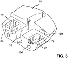
- Fig. 3 illustrates the lube tank 18, which in the Slesinski patent is identified as an insert 70. Since the lube tank 18 is located across the bottom of the differential axle housing 12, excess lubricant 20 is naturally drawn toward the lube tank 18, due to gravity. As disclosed in Slesinski, the lube tank 18 displaces a volume of the lubricant 20 in the bottom of the differential axle housing 12. In the first mechanical device lubrication level control system 10, however, storage of lubricant 20 in the lube tank 18 is used to control an excess of lubricant 20 that can later be utilized by the axle gear set 16.
- the lube tank 18 comprises a polymeric shell that may comprise, for example, closed-cell foam, ABS, PVC plastic or other suitable alternatives.
- the lube tank 18 is hollow therein, where the lubricant 20 is collected.
- pockets 74, 76 that form enclosed pools where foundry sand and ferro-metallic contaminants (not shown) accumulate.
- Magnets 82, 84 are disposed in the pockets 74, 76, for containing the ferro-metallic contaminants.
- the lube tank 18 has a ring gear pocket 32 which provides clearance for a ring gear 34 that is shown in Fig. 1 .
- Bores 104 are used for fastening the lube tank 18 within the differential axle housing 12, wherein Slesinski provides further details on how the lube tank is secured to the differential axle housing 12.
- Filter media 130 is connected to the lube tank 18 so as to further entrap lubricant contaminants.
- the pump tube 23 protrudes into the ring gear pocket 32, anywhere within the sump cavity 14 that does not conflict with the flow of the lubricant is suitable.
- the pump tube 23 is located at the top of the lube tank 18.
- the pump 22 is small and lightweight, the pump 22 is powerful enough to move the lubricant 20, typically high viscous oil, from the lube tank 18 to the sump cavity 14 and vice versa, by way of the pump tube 23 and pick-up/return tube 26.
- the lubricant 20 acts to cool the axle gear set 16 by transferring heat away therefrom. This is achieved within the sump cavity 14 by the lubricant 20 being "splashed" onto the axle gear set 16 and by the rotation of the axle gear set 16 to move the lubricant 20 around in the sump cavity and associated space connected to the sump cavity.
- the pump 22 is reversibly controlled by a motor 24, which in turn is controlled by a first controller 28.
- the first controller 28 may, for example, be a vehicle electronic control unit (ECU) that remotely controls the motor 24, as indicated by the zig-zag arrow shown in Fig. 1 . It is also possible that the first controller 28 may simply be realized as a wheel speed sensor that would turn the pump 22 on and off as a function of the wheel speed. It is also possible that the first controller 28 could simply be an in-dash switch (not shown but common in the art) that a vehicle driver would control.
- ECU vehicle electronic control unit
- the first low loss lubrication system 10 operates in the following manner.
- the motor 24 is powered by the ECU to run. Consequently, the pump 22 is caused to pump lubricant 20 up the pick-up tube 26, out of the lube tank 18, and into the sump cavity 14, thereby making more lubricant 20 available for "splashing" onto the axle gear set 16.
- the opposite procedure is executed when the axle gear set 16 is running at high speed, wherein lubricant 20 is removed from the sump cavity 14 and pumped back into the lube tank 18.
- the ECU is instructed or determines that the lubricant level in the sump cavity 14 needs to be lowered. Consequently, the motor 24 is reversed by the ECU, so as to pump lubricant 20 through the pick-up/return tube 26, from the sump cavity 14, and into the lube tank 18, thereby making less lubricant 20 available for the axle gear set 16.
- a second mechanical device lubrication level control system 40 is illustrated in Fig. 2 having a second differential axle housing 42 with a sump cavity 44 therein.
- the second lubrication level control system 40 further comprises a second axle gear set 46, which is common in the art, in meshing contact therewith.
- the air bladder 50 is shown fully expanded having air A contained therein. Consequently, the lubricant 60 level in Fig. 2 is shown at a midway point in the second differential axle housing 42 (but not limited to this level).
- the lube tank 48 of the second mechanical device lubrication level control system 40 is not a separate structure like the lube tank 18 that is shown in Fig. 3 . Instead, the second lube tank 48 is a specific volume at the bottom of the sump cavity 44, where lubricant 60 tends to collect due to gravity. Subsequently, when the bladder 50 deflates, the lubricant 60 passes through a passage hole 62 and down into the lube tank 48, which tends to fill up the lower portion of the second lube tank 48.
- the lubricant 60 tends to rise up, pass through the passage hole 62, and enter the sump cavity 44, thereby providing more lubricant 60 to the axle gear set 46.
- the air tube 54 protrudes through and is fixedly attached to both the differential axle housing 42 and the lube tank 48, and then protrudes through and is fixedly attached to an upper portion of the air bladder 50.
- the air tube 54 is in pneumatic communication with and connected to an air pressure source 56, for example, a vehicle air pressure tank used for differential locking and/or braking. Since, the base air pressure in the vehicle air pressure source 56 is on the order of 120 psi, which would overstress the air bladder 50, then a pressure regulator 52 is disposed between the air entrance tube 54 and the air pressure source 56. Consequently, the operating pressure within the air bladder would be lowered to, for example, 30 psi.
- the release or removal of pressurized air A from the air pressure source 56, by way of the pressure regulator 52, may be controlled by a second controller 58, for example, a vehicle electronic control unit ECU. It is also possible that the second controller 58 may simply be realized as a wheel speed sensor that would release or remove pressurized air A from the air pressure source 56. Further, it is possible that the second controller 58 could simply be an in-dash switch (not shown but common in the art) that a vehicle driver controls.
- the second low loss lubrication system 40 operates in the following manner.
- the second controller 58 causes pressurized air A from the air pressure source 56 to enter the bladder 50, by way of the air tube 54. Consequently, the pressurized air A expands the bladder 50 within the space of the lube tank 48, causing the lubricant 60 to move up in the sump cavity 44, thereby providing more of the lubricant 60 for "splashing" onto the axle gear set 46.
- the bladder is deflated, which lowers the lubricant level within the sump cavity 44 by deflating the bladder 50. Consequently, the lubricant 60 proceeds to take up space within the top of the second lube tank 48.
- both of the lubrication level control systems 10, 40 require less lube volume therein, which results in increased efficiency and a reduction of the power consumption therein.
- the present invention's use of the lube tank 18 design, and the lube tank 48 with bladder 50 design requires a minimum of 25% less lubricant than an equivalent conventional 12 liter lubricant differential gear assembly. This result is determined by comparing the conventional assembly to the lubrication level control systems 10, 40.
- testing has demonstrated an incremental axle efficiency improvement of 0.15% per drive axle, by way of the lube directors 17, 47 alone.
- the lube level control feature will add further incremental efficiency gains that are at least in the minimum range of 0.1-0.2% incremental efficiency improvement, per drive axle.
- these lubrication level control systems 10, 40 reduce lubricant loss, provide reduced wear at gear contact surfaces, reduce weight, improve heat transfer, reduce oil drag on parts, and use less lubricants 20, 60, thereby better utilizing energy more efficiently along with other benefits, while still providing sufficient availability of the lubricants 20, 60.
Landscapes
- Engineering & Computer Science (AREA)
- General Engineering & Computer Science (AREA)
- Mechanical Engineering (AREA)
- General Details Of Gearings (AREA)
Applications Claiming Priority (1)
| Application Number | Priority Date | Filing Date | Title |
|---|---|---|---|
| US201562165367P | 2015-05-22 | 2015-05-22 |
Publications (3)
| Publication Number | Publication Date |
|---|---|
| EP3098479A2 true EP3098479A2 (de) | 2016-11-30 |
| EP3098479A3 EP3098479A3 (de) | 2017-05-31 |
| EP3098479B1 EP3098479B1 (de) | 2019-05-01 |
Family
ID=56148076
Family Applications (1)
| Application Number | Title | Priority Date | Filing Date |
|---|---|---|---|
| EP16170529.8A Not-in-force EP3098479B1 (de) | 2015-05-22 | 2016-05-20 | Internes schmiermittelniveauregelsystem eines schmieröltanks |
Country Status (3)
| Country | Link |
|---|---|
| US (2) | US10458517B2 (de) |
| EP (1) | EP3098479B1 (de) |
| CN (1) | CN205991155U (de) |
Cited By (2)
| Publication number | Priority date | Publication date | Assignee | Title |
|---|---|---|---|---|
| EP3163125A1 (de) * | 2015-09-29 | 2017-05-03 | ArvinMeritor Technology, LLC | Achsanordnung mit ballasteinsatzanordnung und verfahren zur steuerung davon |
| EP3144564A3 (de) * | 2015-09-14 | 2017-05-03 | ArvinMeritor Technology, LLC | Achsanordnung mit ballasteinsatz |
Families Citing this family (16)
| Publication number | Priority date | Publication date | Assignee | Title |
|---|---|---|---|---|
| JP6721482B2 (ja) * | 2016-10-03 | 2020-07-15 | 株式会社小松製作所 | アクスルアセンブリ |
| EP3388667A1 (de) * | 2017-04-12 | 2018-10-17 | Adwen GmbH | Schmiersystem für einen antriebsstrang einer windturbine |
| USD852244S1 (en) * | 2017-07-04 | 2019-06-25 | Tae Young E&T Co., Ltd. | Fluid guiding device for electrolyzer |
| USD856388S1 (en) * | 2017-09-22 | 2019-08-13 | Thyssenkrupp Elevator Corporation | Lubricant director for an elevator guide rail |
| CN108488337B (zh) * | 2018-06-29 | 2019-11-05 | 浙江广迈捷智能科技有限公司 | 一种凸轮分割器 |
| CN109163078A (zh) * | 2018-09-03 | 2019-01-08 | 合肥工业大学 | 具有油量控制机构的汽车变速器 |
| EP3734120A1 (de) * | 2019-05-02 | 2020-11-04 | Flender GmbH | Getriebe mit reduzierter verlustleistung, betriebsverfahren und industrie-applikation |
| US11125319B2 (en) * | 2019-06-18 | 2021-09-21 | Deere & Company | Limited oil displacement system |
| US11421775B2 (en) * | 2019-10-31 | 2022-08-23 | Deere & Company | Pressurized aeration prevention reservoir |
| US20210293326A1 (en) * | 2020-03-18 | 2021-09-23 | Karma Automotive Llc | Transmission system for an electric vehicle |
| DE102021125200A1 (de) * | 2021-09-29 | 2023-03-30 | Audi Aktiengesellschaft | Antriebseinrichtung für ein Kraftfahrzeug mit einem in einem Maschinengehäuse ausgebildeten Betriebsmitteltank |
| FR3132132B1 (fr) * | 2022-01-25 | 2024-01-19 | Renault Sas | Déflecteur d’huile comprenant un moyen de captation de particules métalliques. |
| DE102022213794A1 (de) * | 2022-12-16 | 2024-06-27 | Zf Friedrichshafen Ag | Ölsumpf im Ölsumpf |
| CN116656407B (zh) * | 2023-05-15 | 2025-07-15 | 安徽华梦塑业有限公司 | 一种用于化粪池处理用安全除臭系统 |
| CN116371062B (zh) * | 2023-06-05 | 2023-08-01 | 东营国安化工有限公司 | 一种废润滑油过滤釜及方法 |
| CN117823612B (zh) * | 2024-03-06 | 2024-05-31 | 河南蒲瑞精密机械有限公司 | 一种旋转注油式行星减速机 |
Citations (2)
| Publication number | Priority date | Publication date | Assignee | Title |
|---|---|---|---|---|
| US6938731B2 (en) | 2003-02-05 | 2005-09-06 | Dana Corporation | Drive axle assembly with insert |
| US8152674B2 (en) | 2008-08-15 | 2012-04-10 | Arvinmeritor Technology, Llc | Auxiliary lubrication pump for carriers |
Family Cites Families (32)
| Publication number | Priority date | Publication date | Assignee | Title |
|---|---|---|---|---|
| US2622699A (en) * | 1950-11-15 | 1952-12-23 | Internat Derrick And Equipment | Gear case with magnetic lubricant purifying means |
| US4082170A (en) | 1977-02-14 | 1978-04-04 | Caterpillar Tractor Co. | Final drive bladder |
| US4468981A (en) | 1981-10-02 | 1984-09-04 | Rockwell International Corporation | Drive axle and fluid pump assembly |
| DE3208100C2 (de) | 1982-03-06 | 1984-09-06 | Zahnradfabrik Friedrichshafen Ag, 7990 Friedrichshafen | Tauchschmierung für ein Getriebe |
| DE3209514C2 (de) * | 1982-03-16 | 1984-04-26 | BHS-Bayerische Berg-, Hütten- und Salzwerke AG, 8000 München | In sich geschlossene Getriebeanlage mit Druckschmierung |
| DE3566722D1 (en) * | 1984-07-06 | 1989-01-12 | Neuenstein Zahnradwerk | Immersion lubrication system for gear-boxes of motor vehicles |
| CH675758A5 (de) * | 1987-04-02 | 1990-10-31 | Walter Baiker Dipl Ing | |
| FR2658577A1 (fr) * | 1990-02-20 | 1991-08-23 | Aerospatiale | Dispositif de lubrification de secours pour reducteur notamment pour boite de transmission principale de giravion. |
| US5251725A (en) * | 1992-07-07 | 1993-10-12 | Castrol Limited | Lubrication of power drive comprising large diameter gear |
| US5279391A (en) * | 1993-02-03 | 1994-01-18 | Eaton Corporation | Dry sump mechanical transmission |
| US5294350A (en) | 1993-04-02 | 1994-03-15 | General Motors Corporation | Magnetic particle separator |
| US5643127A (en) * | 1995-03-06 | 1997-07-01 | Toyota Jidosha Kabushiki Kaisha | Vehicle power transmission having fluid-tight enclosure accommodating lubricating points and storing lubricating oil delivered from mechanical oil pump |
| US5709135A (en) * | 1996-04-04 | 1998-01-20 | Dana Corporation | Clam-shell shaped differential housing and lubrication system therefor |
| US6299561B1 (en) | 1999-07-21 | 2001-10-09 | Meritor Heavy Vehicle Systems, Llc | Device for controlling level of gear lubricant as a function of speed |
| US6702703B2 (en) | 2001-01-18 | 2004-03-09 | Dana Corporation | Lubrication pump for inter-axle differential |
| US6855083B1 (en) | 2001-01-18 | 2005-02-15 | Dana Corporation | Lubrication pump for inter-axle differential |
| DE10359505A1 (de) | 2003-12-18 | 2005-07-14 | Bayerische Motoren Werke Ag | Getriebe mit einem sich in Abhängigkeit von der Getriebeöltemperatur dehnenden Dehnkörper |
| US7241246B2 (en) * | 2004-11-18 | 2007-07-10 | American Axle & Manufacturing, Inc. | Differential assembly with cover gasket having integral magnet |
| JP2006200730A (ja) * | 2004-12-24 | 2006-08-03 | Nissan Motor Co Ltd | ファイナルドライブの潤滑構造 |
| JP4500177B2 (ja) * | 2005-02-21 | 2010-07-14 | アイシン・エーアイ株式会社 | 変速機 |
| US7189178B2 (en) | 2005-03-16 | 2007-03-13 | American Axle & Manufacturing, Inc. | Drive axle with variable oil flow mechanism |
| JP2007107688A (ja) * | 2005-10-17 | 2007-04-26 | Nachi Fujikoshi Corp | 潤滑装置 |
| EP2230423A1 (de) | 2009-03-17 | 2010-09-22 | Meritor Technology, Inc. | Übertragungssystem |
| GB2471651A (en) | 2009-06-30 | 2011-01-12 | Meritor Technology Inc | Axle crown wheel housing with nested bowls defining a reservoir |
| GB2471653A (en) * | 2009-06-30 | 2011-01-12 | Meritor Technology Inc | A method of controlling a fluid level around a transmission gear |
| US8707815B2 (en) * | 2011-03-21 | 2014-04-29 | Deere & Company | Power transfer box lubrication device |
| US9068645B2 (en) * | 2012-12-14 | 2015-06-30 | GM Global Technology Operations LLC | Transmission sump level control system |
| US9103433B2 (en) | 2013-02-26 | 2015-08-11 | Arvinmeritor Technology, Llc | Axle assembly and method of lubrication control |
| EP2801737B1 (de) | 2013-05-08 | 2016-07-20 | Meritor Technology, LLC | Achsenanordnung und Verfahren zum Umrüsten einer Achsenanordnung |
| US10036467B2 (en) * | 2015-09-29 | 2018-07-31 | Arvinmeritor Technology, Llc | Axle assembly having a ballast insert assembly and a method of control |
| US10634053B2 (en) * | 2015-12-21 | 2020-04-28 | United Technologies Corporation | Electric windmill pump for gearbox durability |
| JP2018152946A (ja) * | 2017-03-10 | 2018-09-27 | 三菱自動車工業株式会社 | 車両の制御装置 |
-
2016
- 2016-05-18 US US15/157,561 patent/US10458517B2/en active Active
- 2016-05-20 EP EP16170529.8A patent/EP3098479B1/de not_active Not-in-force
- 2016-05-23 CN CN201620834102.8U patent/CN205991155U/zh not_active Expired - Fee Related
-
2019
- 2019-09-10 US US16/565,741 patent/US10605331B2/en active Active
Patent Citations (2)
| Publication number | Priority date | Publication date | Assignee | Title |
|---|---|---|---|---|
| US6938731B2 (en) | 2003-02-05 | 2005-09-06 | Dana Corporation | Drive axle assembly with insert |
| US8152674B2 (en) | 2008-08-15 | 2012-04-10 | Arvinmeritor Technology, Llc | Auxiliary lubrication pump for carriers |
Cited By (4)
| Publication number | Priority date | Publication date | Assignee | Title |
|---|---|---|---|---|
| EP3144564A3 (de) * | 2015-09-14 | 2017-05-03 | ArvinMeritor Technology, LLC | Achsanordnung mit ballasteinsatz |
| US9677661B2 (en) | 2015-09-14 | 2017-06-13 | Arvinmeritor Technology, Llc | Axle assembly having a ballast insert |
| EP3163125A1 (de) * | 2015-09-29 | 2017-05-03 | ArvinMeritor Technology, LLC | Achsanordnung mit ballasteinsatzanordnung und verfahren zur steuerung davon |
| US10036467B2 (en) | 2015-09-29 | 2018-07-31 | Arvinmeritor Technology, Llc | Axle assembly having a ballast insert assembly and a method of control |
Also Published As
| Publication number | Publication date |
|---|---|
| US10458517B2 (en) | 2019-10-29 |
| EP3098479A3 (de) | 2017-05-31 |
| US20160341301A1 (en) | 2016-11-24 |
| US20200003276A1 (en) | 2020-01-02 |
| US10605331B2 (en) | 2020-03-31 |
| EP3098479B1 (de) | 2019-05-01 |
| CN205991155U (zh) | 2017-03-01 |
Similar Documents
| Publication | Publication Date | Title |
|---|---|---|
| US10605331B2 (en) | Internal lube tank lube level control system | |
| CA2829627C (en) | Clogged filter detection system and method | |
| EP2675681B1 (de) | Modulationssteuersystem und -verfahren für ein hybridgetriebe | |
| EP3163125B1 (de) | Achsanordnung mit ballasteinsatzanordnung und verfahren zur steuerung davon | |
| JP2002524337A (ja) | エネルギ管理システム | |
| JP2010513799A (ja) | 統合クラッチ及びアクチュエータユニットを備える電動液圧式トルク伝達装置 | |
| EP2973961A1 (de) | Elektrische pumpe für ein hybridfahrzeug | |
| KR20140033167A (ko) | 저 레벨 오일 검출 시스템 및 방법 | |
| JP2010053997A (ja) | 動力伝達装置 | |
| CN110939690A (zh) | 一种车辆双驱动减速器和汽车 | |
| US20120288380A1 (en) | Pump-motor assembly | |
| EP3035506A1 (de) | Elektromechanische Servolenkung zur Anwendung in schweren Nutzfahrzeugen | |
| JP2018152945A (ja) | 電動機の潤滑装置 | |
| US4152894A (en) | Control system of hydraulic torque converter of transport vehicle | |
| EP1111273A2 (de) | Aktive Öldrucksteuerung für negative "g" Flugzuständen | |
| CN119189663A (zh) | 商用车电驱桥及车辆 | |
| CN211924816U (zh) | 一种车辆双驱动减速器和汽车 | |
| KR100559643B1 (ko) | 자동차의 스티어링 인터미드 샤프트 | |
| KR100862219B1 (ko) | 리어액슬 | |
| KR102896078B1 (ko) | 차량 파워트레인의 eop 제어방법 | |
| JP2008029170A (ja) | 電動機の冷却構造 | |
| AU761471C (en) | Energy management system | |
| JPH04203657A (ja) | 車両用変速機の給油装置 | |
| JP2015135151A (ja) | 変速機 | |
| AU7732201A (en) | Energy management system |
Legal Events
| Date | Code | Title | Description |
|---|---|---|---|
| PUAI | Public reference made under article 153(3) epc to a published international application that has entered the european phase |
Free format text: ORIGINAL CODE: 0009012 |
|
| AK | Designated contracting states |
Kind code of ref document: A2 Designated state(s): AL AT BE BG CH CY CZ DE DK EE ES FI FR GB GR HR HU IE IS IT LI LT LU LV MC MK MT NL NO PL PT RO RS SE SI SK SM TR |
|
| AX | Request for extension of the european patent |
Extension state: BA ME |
|
| PUAL | Search report despatched |
Free format text: ORIGINAL CODE: 0009013 |
|
| AK | Designated contracting states |
Kind code of ref document: A3 Designated state(s): AL AT BE BG CH CY CZ DE DK EE ES FI FR GB GR HR HU IE IS IT LI LT LU LV MC MK MT NL NO PL PT RO RS SE SI SK SM TR |
|
| AX | Request for extension of the european patent |
Extension state: BA ME |
|
| RIC1 | Information provided on ipc code assigned before grant |
Ipc: F16H 1/00 20060101ALN20170427BHEP Ipc: F16H 57/04 20100101AFI20170427BHEP |
|
| STAA | Information on the status of an ep patent application or granted ep patent |
Free format text: STATUS: REQUEST FOR EXAMINATION WAS MADE |
|
| 17P | Request for examination filed |
Effective date: 20171130 |
|
| RBV | Designated contracting states (corrected) |
Designated state(s): AL AT BE BG CH CY CZ DE DK EE ES FI FR GB GR HR HU IE IS IT LI LT LU LV MC MK MT NL NO PL PT RO RS SE SI SK SM TR |
|
| STAA | Information on the status of an ep patent application or granted ep patent |
Free format text: STATUS: EXAMINATION IS IN PROGRESS |
|
| 17Q | First examination report despatched |
Effective date: 20180313 |
|
| RIC1 | Information provided on ipc code assigned before grant |
Ipc: F16H 57/04 20100101AFI20181016BHEP Ipc: F16H 1/00 20060101ALN20181016BHEP |
|
| GRAP | Despatch of communication of intention to grant a patent |
Free format text: ORIGINAL CODE: EPIDOSNIGR1 |
|
| STAA | Information on the status of an ep patent application or granted ep patent |
Free format text: STATUS: GRANT OF PATENT IS INTENDED |
|
| RIC1 | Information provided on ipc code assigned before grant |
Ipc: F16H 1/00 20060101ALN20181024BHEP Ipc: F16H 57/04 20100101AFI20181024BHEP |
|
| INTG | Intention to grant announced |
Effective date: 20181123 |
|
| GRAS | Grant fee paid |
Free format text: ORIGINAL CODE: EPIDOSNIGR3 |
|
| GRAA | (expected) grant |
Free format text: ORIGINAL CODE: 0009210 |
|
| STAA | Information on the status of an ep patent application or granted ep patent |
Free format text: STATUS: THE PATENT HAS BEEN GRANTED |
|
| AK | Designated contracting states |
Kind code of ref document: B1 Designated state(s): AL AT BE BG CH CY CZ DE DK EE ES FI FR GB GR HR HU IE IS IT LI LT LU LV MC MK MT NL NO PL PT RO RS SE SI SK SM TR |
|
| REG | Reference to a national code |
Ref country code: GB Ref legal event code: FG4D |
|
| REG | Reference to a national code |
Ref country code: CH Ref legal event code: EP Ref country code: AT Ref legal event code: REF Ref document number: 1127362 Country of ref document: AT Kind code of ref document: T Effective date: 20190515 |
|
| REG | Reference to a national code |
Ref country code: DE Ref legal event code: R096 Ref document number: 602016013050 Country of ref document: DE |
|
| REG | Reference to a national code |
Ref country code: IE Ref legal event code: FG4D |
|
| REG | Reference to a national code |
Ref country code: NL Ref legal event code: MP Effective date: 20190501 |
|
| REG | Reference to a national code |
Ref country code: LT Ref legal event code: MG4D |
|
| PG25 | Lapsed in a contracting state [announced via postgrant information from national office to epo] |
Ref country code: SE Free format text: LAPSE BECAUSE OF FAILURE TO SUBMIT A TRANSLATION OF THE DESCRIPTION OR TO PAY THE FEE WITHIN THE PRESCRIBED TIME-LIMIT Effective date: 20190501 Ref country code: NL Free format text: LAPSE BECAUSE OF FAILURE TO SUBMIT A TRANSLATION OF THE DESCRIPTION OR TO PAY THE FEE WITHIN THE PRESCRIBED TIME-LIMIT Effective date: 20190501 Ref country code: PT Free format text: LAPSE BECAUSE OF FAILURE TO SUBMIT A TRANSLATION OF THE DESCRIPTION OR TO PAY THE FEE WITHIN THE PRESCRIBED TIME-LIMIT Effective date: 20190901 Ref country code: HR Free format text: LAPSE BECAUSE OF FAILURE TO SUBMIT A TRANSLATION OF THE DESCRIPTION OR TO PAY THE FEE WITHIN THE PRESCRIBED TIME-LIMIT Effective date: 20190501 Ref country code: AL Free format text: LAPSE BECAUSE OF FAILURE TO SUBMIT A TRANSLATION OF THE DESCRIPTION OR TO PAY THE FEE WITHIN THE PRESCRIBED TIME-LIMIT Effective date: 20190501 Ref country code: FI Free format text: LAPSE BECAUSE OF FAILURE TO SUBMIT A TRANSLATION OF THE DESCRIPTION OR TO PAY THE FEE WITHIN THE PRESCRIBED TIME-LIMIT Effective date: 20190501 Ref country code: NO Free format text: LAPSE BECAUSE OF FAILURE TO SUBMIT A TRANSLATION OF THE DESCRIPTION OR TO PAY THE FEE WITHIN THE PRESCRIBED TIME-LIMIT Effective date: 20190801 Ref country code: ES Free format text: LAPSE BECAUSE OF FAILURE TO SUBMIT A TRANSLATION OF THE DESCRIPTION OR TO PAY THE FEE WITHIN THE PRESCRIBED TIME-LIMIT Effective date: 20190501 Ref country code: LT Free format text: LAPSE BECAUSE OF FAILURE TO SUBMIT A TRANSLATION OF THE DESCRIPTION OR TO PAY THE FEE WITHIN THE PRESCRIBED TIME-LIMIT Effective date: 20190501 |
|
| PG25 | Lapsed in a contracting state [announced via postgrant information from national office to epo] |
Ref country code: BG Free format text: LAPSE BECAUSE OF FAILURE TO SUBMIT A TRANSLATION OF THE DESCRIPTION OR TO PAY THE FEE WITHIN THE PRESCRIBED TIME-LIMIT Effective date: 20190801 Ref country code: RS Free format text: LAPSE BECAUSE OF FAILURE TO SUBMIT A TRANSLATION OF THE DESCRIPTION OR TO PAY THE FEE WITHIN THE PRESCRIBED TIME-LIMIT Effective date: 20190501 Ref country code: LV Free format text: LAPSE BECAUSE OF FAILURE TO SUBMIT A TRANSLATION OF THE DESCRIPTION OR TO PAY THE FEE WITHIN THE PRESCRIBED TIME-LIMIT Effective date: 20190501 Ref country code: GR Free format text: LAPSE BECAUSE OF FAILURE TO SUBMIT A TRANSLATION OF THE DESCRIPTION OR TO PAY THE FEE WITHIN THE PRESCRIBED TIME-LIMIT Effective date: 20190802 |
|
| REG | Reference to a national code |
Ref country code: AT Ref legal event code: MK05 Ref document number: 1127362 Country of ref document: AT Kind code of ref document: T Effective date: 20190501 |
|
| REG | Reference to a national code |
Ref country code: CH Ref legal event code: PL |
|
| PG25 | Lapsed in a contracting state [announced via postgrant information from national office to epo] |
Ref country code: IS Free format text: LAPSE BECAUSE OF FAILURE TO SUBMIT A TRANSLATION OF THE DESCRIPTION OR TO PAY THE FEE WITHIN THE PRESCRIBED TIME-LIMIT Effective date: 20190901 |
|
| PG25 | Lapsed in a contracting state [announced via postgrant information from national office to epo] |
Ref country code: AT Free format text: LAPSE BECAUSE OF FAILURE TO SUBMIT A TRANSLATION OF THE DESCRIPTION OR TO PAY THE FEE WITHIN THE PRESCRIBED TIME-LIMIT Effective date: 20190501 Ref country code: DK Free format text: LAPSE BECAUSE OF FAILURE TO SUBMIT A TRANSLATION OF THE DESCRIPTION OR TO PAY THE FEE WITHIN THE PRESCRIBED TIME-LIMIT Effective date: 20190501 Ref country code: LI Free format text: LAPSE BECAUSE OF NON-PAYMENT OF DUE FEES Effective date: 20190531 Ref country code: CH Free format text: LAPSE BECAUSE OF NON-PAYMENT OF DUE FEES Effective date: 20190531 Ref country code: EE Free format text: LAPSE BECAUSE OF FAILURE TO SUBMIT A TRANSLATION OF THE DESCRIPTION OR TO PAY THE FEE WITHIN THE PRESCRIBED TIME-LIMIT Effective date: 20190501 Ref country code: RO Free format text: LAPSE BECAUSE OF FAILURE TO SUBMIT A TRANSLATION OF THE DESCRIPTION OR TO PAY THE FEE WITHIN THE PRESCRIBED TIME-LIMIT Effective date: 20190501 Ref country code: SK Free format text: LAPSE BECAUSE OF FAILURE TO SUBMIT A TRANSLATION OF THE DESCRIPTION OR TO PAY THE FEE WITHIN THE PRESCRIBED TIME-LIMIT Effective date: 20190501 Ref country code: CZ Free format text: LAPSE BECAUSE OF FAILURE TO SUBMIT A TRANSLATION OF THE DESCRIPTION OR TO PAY THE FEE WITHIN THE PRESCRIBED TIME-LIMIT Effective date: 20190501 Ref country code: MC Free format text: LAPSE BECAUSE OF FAILURE TO SUBMIT A TRANSLATION OF THE DESCRIPTION OR TO PAY THE FEE WITHIN THE PRESCRIBED TIME-LIMIT Effective date: 20190501 |
|
| REG | Reference to a national code |
Ref country code: DE Ref legal event code: R097 Ref document number: 602016013050 Country of ref document: DE |
|
| REG | Reference to a national code |
Ref country code: BE Ref legal event code: MM Effective date: 20190531 |
|
| PG25 | Lapsed in a contracting state [announced via postgrant information from national office to epo] |
Ref country code: SM Free format text: LAPSE BECAUSE OF FAILURE TO SUBMIT A TRANSLATION OF THE DESCRIPTION OR TO PAY THE FEE WITHIN THE PRESCRIBED TIME-LIMIT Effective date: 20190501 Ref country code: IT Free format text: LAPSE BECAUSE OF FAILURE TO SUBMIT A TRANSLATION OF THE DESCRIPTION OR TO PAY THE FEE WITHIN THE PRESCRIBED TIME-LIMIT Effective date: 20190501 Ref country code: LU Free format text: LAPSE BECAUSE OF NON-PAYMENT OF DUE FEES Effective date: 20190520 |
|
| PLBE | No opposition filed within time limit |
Free format text: ORIGINAL CODE: 0009261 |
|
| STAA | Information on the status of an ep patent application or granted ep patent |
Free format text: STATUS: NO OPPOSITION FILED WITHIN TIME LIMIT |
|
| PG25 | Lapsed in a contracting state [announced via postgrant information from national office to epo] |
Ref country code: TR Free format text: LAPSE BECAUSE OF FAILURE TO SUBMIT A TRANSLATION OF THE DESCRIPTION OR TO PAY THE FEE WITHIN THE PRESCRIBED TIME-LIMIT Effective date: 20190501 |
|
| 26N | No opposition filed |
Effective date: 20200204 |
|
| PG25 | Lapsed in a contracting state [announced via postgrant information from national office to epo] |
Ref country code: PL Free format text: LAPSE BECAUSE OF FAILURE TO SUBMIT A TRANSLATION OF THE DESCRIPTION OR TO PAY THE FEE WITHIN THE PRESCRIBED TIME-LIMIT Effective date: 20190501 Ref country code: IE Free format text: LAPSE BECAUSE OF NON-PAYMENT OF DUE FEES Effective date: 20190520 |
|
| PG25 | Lapsed in a contracting state [announced via postgrant information from national office to epo] |
Ref country code: SI Free format text: LAPSE BECAUSE OF FAILURE TO SUBMIT A TRANSLATION OF THE DESCRIPTION OR TO PAY THE FEE WITHIN THE PRESCRIBED TIME-LIMIT Effective date: 20190501 Ref country code: BE Free format text: LAPSE BECAUSE OF NON-PAYMENT OF DUE FEES Effective date: 20190531 |
|
| PG25 | Lapsed in a contracting state [announced via postgrant information from national office to epo] |
Ref country code: FR Free format text: LAPSE BECAUSE OF NON-PAYMENT OF DUE FEES Effective date: 20190701 |
|
| GBPC | Gb: european patent ceased through non-payment of renewal fee |
Effective date: 20200520 |
|
| PG25 | Lapsed in a contracting state [announced via postgrant information from national office to epo] |
Ref country code: GB Free format text: LAPSE BECAUSE OF NON-PAYMENT OF DUE FEES Effective date: 20200520 |
|
| PG25 | Lapsed in a contracting state [announced via postgrant information from national office to epo] |
Ref country code: CY Free format text: LAPSE BECAUSE OF FAILURE TO SUBMIT A TRANSLATION OF THE DESCRIPTION OR TO PAY THE FEE WITHIN THE PRESCRIBED TIME-LIMIT Effective date: 20190501 |
|
| PG25 | Lapsed in a contracting state [announced via postgrant information from national office to epo] |
Ref country code: HU Free format text: LAPSE BECAUSE OF FAILURE TO SUBMIT A TRANSLATION OF THE DESCRIPTION OR TO PAY THE FEE WITHIN THE PRESCRIBED TIME-LIMIT; INVALID AB INITIO Effective date: 20160520 Ref country code: MT Free format text: LAPSE BECAUSE OF FAILURE TO SUBMIT A TRANSLATION OF THE DESCRIPTION OR TO PAY THE FEE WITHIN THE PRESCRIBED TIME-LIMIT Effective date: 20190501 |
|
| PG25 | Lapsed in a contracting state [announced via postgrant information from national office to epo] |
Ref country code: MK Free format text: LAPSE BECAUSE OF FAILURE TO SUBMIT A TRANSLATION OF THE DESCRIPTION OR TO PAY THE FEE WITHIN THE PRESCRIBED TIME-LIMIT Effective date: 20190501 |
|
| P01 | Opt-out of the competence of the unified patent court (upc) registered |
Effective date: 20230523 |
|
| PGFP | Annual fee paid to national office [announced via postgrant information from national office to epo] |
Ref country code: DE Payment date: 20230419 Year of fee payment: 8 |
|
| REG | Reference to a national code |
Ref country code: DE Ref legal event code: R119 Ref document number: 602016013050 Country of ref document: DE |
|
| PG25 | Lapsed in a contracting state [announced via postgrant information from national office to epo] |
Ref country code: DE Free format text: LAPSE BECAUSE OF NON-PAYMENT OF DUE FEES Effective date: 20241203 |