EP3098475B1 - Dämpfende freilaufriemenscheiben - Google Patents
Dämpfende freilaufriemenscheiben Download PDFInfo
- Publication number
- EP3098475B1 EP3098475B1 EP15175147.6A EP15175147A EP3098475B1 EP 3098475 B1 EP3098475 B1 EP 3098475B1 EP 15175147 A EP15175147 A EP 15175147A EP 3098475 B1 EP3098475 B1 EP 3098475B1
- Authority
- EP
- European Patent Office
- Prior art keywords
- damping
- pulley
- spring
- friction
- hub
- Prior art date
- Legal status (The legal status is an assumption and is not a legal conclusion. Google has not performed a legal analysis and makes no representation as to the accuracy of the status listed.)
- Not-in-force
Links
- 238000013016 damping Methods 0.000 title claims description 59
- 230000000694 effects Effects 0.000 description 9
- 238000000034 method Methods 0.000 description 4
- 238000005516 engineering process Methods 0.000 description 3
- 238000002485 combustion reaction Methods 0.000 description 2
- 238000012986 modification Methods 0.000 description 2
- 230000004048 modification Effects 0.000 description 2
- 230000001360 synchronised effect Effects 0.000 description 2
- 125000002015 acyclic group Chemical group 0.000 description 1
- 230000007812 deficiency Effects 0.000 description 1
- 238000010586 diagram Methods 0.000 description 1
- 230000005284 excitation Effects 0.000 description 1
- 238000004880 explosion Methods 0.000 description 1
Images



Classifications
-
- F—MECHANICAL ENGINEERING; LIGHTING; HEATING; WEAPONS; BLASTING
- F16—ENGINEERING ELEMENTS AND UNITS; GENERAL MEASURES FOR PRODUCING AND MAINTAINING EFFECTIVE FUNCTIONING OF MACHINES OR INSTALLATIONS; THERMAL INSULATION IN GENERAL
- F16H—GEARING
- F16H55/00—Elements with teeth or friction surfaces for conveying motion; Worms, pulleys or sheaves for gearing mechanisms
- F16H55/32—Friction members
- F16H55/36—Pulleys
-
- F—MECHANICAL ENGINEERING; LIGHTING; HEATING; WEAPONS; BLASTING
- F16—ENGINEERING ELEMENTS AND UNITS; GENERAL MEASURES FOR PRODUCING AND MAINTAINING EFFECTIVE FUNCTIONING OF MACHINES OR INSTALLATIONS; THERMAL INSULATION IN GENERAL
- F16D—COUPLINGS FOR TRANSMITTING ROTATION; CLUTCHES; BRAKES
- F16D41/00—Freewheels or freewheel clutches
- F16D41/02—Freewheels or freewheel clutches disengaged by contact of a part of or on the freewheel or freewheel clutch with a stationarily-mounted member
-
- F—MECHANICAL ENGINEERING; LIGHTING; HEATING; WEAPONS; BLASTING
- F16—ENGINEERING ELEMENTS AND UNITS; GENERAL MEASURES FOR PRODUCING AND MAINTAINING EFFECTIVE FUNCTIONING OF MACHINES OR INSTALLATIONS; THERMAL INSULATION IN GENERAL
- F16D—COUPLINGS FOR TRANSMITTING ROTATION; CLUTCHES; BRAKES
- F16D41/00—Freewheels or freewheel clutches
- F16D41/20—Freewheels or freewheel clutches with expandable or contractable clamping ring or band
- F16D41/206—Freewheels or freewheel clutches with expandable or contractable clamping ring or band having axially adjacent coils, e.g. helical wrap-springs
-
- F—MECHANICAL ENGINEERING; LIGHTING; HEATING; WEAPONS; BLASTING
- F16—ENGINEERING ELEMENTS AND UNITS; GENERAL MEASURES FOR PRODUCING AND MAINTAINING EFFECTIVE FUNCTIONING OF MACHINES OR INSTALLATIONS; THERMAL INSULATION IN GENERAL
- F16F—SPRINGS; SHOCK-ABSORBERS; MEANS FOR DAMPING VIBRATION
- F16F15/00—Suppression of vibrations in systems; Means or arrangements for avoiding or reducing out-of-balance forces, e.g. due to motion
- F16F15/10—Suppression of vibrations in rotating systems by making use of members moving with the system
- F16F15/12—Suppression of vibrations in rotating systems by making use of members moving with the system using elastic members or friction-damping members, e.g. between a rotating shaft and a gyratory mass mounted thereon
- F16F15/121—Suppression of vibrations in rotating systems by making use of members moving with the system using elastic members or friction-damping members, e.g. between a rotating shaft and a gyratory mass mounted thereon using springs as elastic members, e.g. metallic springs
- F16F15/1216—Torsional springs, e.g. torsion bar or torsionally-loaded coil springs
-
- F—MECHANICAL ENGINEERING; LIGHTING; HEATING; WEAPONS; BLASTING
- F16—ENGINEERING ELEMENTS AND UNITS; GENERAL MEASURES FOR PRODUCING AND MAINTAINING EFFECTIVE FUNCTIONING OF MACHINES OR INSTALLATIONS; THERMAL INSULATION IN GENERAL
- F16H—GEARING
- F16H55/00—Elements with teeth or friction surfaces for conveying motion; Worms, pulleys or sheaves for gearing mechanisms
- F16H55/32—Friction members
- F16H55/36—Pulleys
- F16H2055/366—Pulleys with means providing resilience or vibration damping
Definitions
- the present patent application relates to a belt pulley, and specifically, to an overrunning alternator damping pulley for automotive alternators.
- the running speed of the traditional automotive alternator pulley is synchronized with the car engine. If the speed of the engine changes, the speed of the alternator changes accordingly.
- the output torque and speed of an internal combustion engine are acyclic due to the explosion of the cylinders.
- the speed of the alternator pulley changes.
- the rotor speed of the alternator is suddenly synchronized with the speed of the engine. The impact will be formed between the belt and the pulley, reducing belt life and producing noise, in a resulting engine Front End Accessory Drive (FEAD).
- the engine crankshaft Before the engine is stopped, the engine crankshaft has a short positive and negative direction swing.
- the excitation coil in the rotor causes damage and reduces the life of the alternator by centrifugal force.
- a Overrunning Alternator Pulley includes a pulley wheel, a pulley shaft, an upper ball bearing and lower ball bearing located between the pulley wheel and the pulley shaft, and a overrunning clutch that is arranged between the upper ball bearing and the lower ball bearing.
- the structure of the above overrunning pulley is complicated. It has only overrunning function but no damping function.
- US 6 083 130 A describes a serpentine belt drive system for an automotive vehicle comprising a drive assembly including an internal combustion engine having an output shaft with a driving pulley thereon rotatable about a driving pulley axis.
- the overrunning alternator damping pulley comprises a pulley body, two ball bearings provided on both ends of a shaft hole of the pulley body; and a hub for supporting the two ball bearings.
- At least one spring holder is provided on the hub.
- At least one friction spring is engaged with the spring holder.
- One end of the friction spring is inserted to the spring holder.
- Another end of the friction spring forms a free end spirally extending along an axial direction of the hub.
- the outer ring of the friction spring is in contact with an inner wall of the pulley body.
- a damping groove is provided where the inner wall of the pulley body is in contact with the friction spring.
- a damping space is provided for the friction spring by the damping groove.
- the damping groove may have an annular shape.
- the damping groove may have a variable width according to the damping requirement.
- the damping groove may be provided near an end portion of the spring holder.
- the spring holder may have an arc groove.
- One end of the friction spring which connects to the spring holder may be clamped in the arc groove.
- Two sides of the spring holder may be inserted to two friction springs respectively.
- the two friction springs may be concentrically set at the two sides of the spring holder with same rotation direction.
- a number of the spring holder may be two and a number of the friction spring may be two.
- Two friction springs may be disposed opposite to each other in two sides of the spring holder correspondingly.
- Two locking blocks may be set on an opposite sides of the hub respectively; two locking grooves corresponding to the two locking blocks may be set in the spring holder, with the locking blocks locked in the locking grooves.
- the locking blocks may be located in the middle of the hub.
- the spring holder and the hub may be separately disposed or integrated.
- the overrunning alternator damping pulley of the present patent application has an extremely simple structure.
- expansion and shrink of the outer ring of the friction spring it can be engaged and disengaged with the pulley body.
- the outer ring of the friction spring expands and engages with the pulley body.
- the hub and the pulley body are combined, so that the hub and the pulley body rotate synchronously and transmit a driving force power.
- the outer ring of the friction spring shrinks. It slips in the inner wall of the pulley body.
- the hub and the pulley body are disengaged.
- the hub and the pulley body each rotates, playing a protection and damping effect.
- a damping groove is provided on the place where the inner wall and friction spring contacts.
- the damping groove further provides a damping space for the friction spring, so that it plays a further damping effect at the moment of engaging.
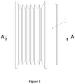
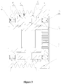
- an overrunning alternator damping pulley includes a pulley body 1, two ball bearings 2 and a hub.
- the two ball bearings 2 are provided on both ends of a shaft hole of the pulley body 1.
- the hub 3 is used to support the two ball bearings 2.
- the ball bearings 2 and the pulley body 1 interference fit.
- At least one spring holder 4 is provided on the hub 3.
- At least one friction spring 5 is installed on the spring holder 4. One end of the friction spring 5 is connected to the spring holder 4. Another end of the friction spring 5 forms a free end spirally extending along the axial direction of the hub 3.
- the outer ring of the friction spring 5 is in contact with the inner wall of the pulley body 1.
- the friction spring 5 By expansion and shrink of the outer ring the friction spring 5, it can be engaged and disengaged with the pulley body 1. It plays a good role in the overrunning clutch. Specifically, when the rotation speed of the pulley body 1 is higher than that of the hub 3, the outer ring of the friction spring 5 expands and engages with the pulley body 1. The hub 3 and the pulley body 1 are combined, so that the hub 3 and the pulley body 1 rotate synchronously and transmit a driving force power. When the rotation speed of the pulley body 1 is lower than that of the hub 3, the outer ring of the friction spring 5 shrinks. It slips in the shaft hole of the pulley body 1. The hub 3 and the pulley body 1 are disengaged. The hub 3 and the pulley body 1 each rotate, protecting the apparatus and achieving a damping effect.
- a damping groove 6 is provided on the place where the inner wall and friction spring 5 contacts.
- the damping groove 6 further provides a damping space for the friction spring 5, so that it provides a further damping effect at the moment of engaging.
- the damping groove 6 is in an annular shape. It has a variable width according to the damping requirement.
- the damping groove 6 is set at the place near the end portion of the spring holder 4.
- one or more friction spring 5 can be set as needed. For more than one friction spring 5, they can be mounted back to back (they are respectively mounted on both sides of the spring holder 4), or they can be mounted parallel to parallel (one friction spring 5 is mounted on one spring holder 4).
- both sides of the spring holder 4 are inserted to two friction springs 5 respectively.
- the two friction springs 5 are concentrically set at the two sides of the spring holder 4 with an opposite rotation direction.
- both sides of the spring holder 4 are set with an arc groove 7.
- One end of each friction spring 5 which connects to the spring holder 4 is clamped in the arc groove 7.
- the number of the spring holder 4 is two and the number of the friction spring 5 is two.
- Two friction springs 5 are oppositely disposed in the corresponding spring holder 4.
- two locking blocks 31 are set on the opposite sides of the hub 3 respectively.
- Two locking grooves 41 corresponding to the two locking blocks 31 are set in the spring holder 4.
- the locking blocks 31 are locked in the locking grooves 41.
- the locking blocks 31 are located in the middle of the hub 3. It makes the two friction springs 5 locate at the middle of the hub 3, in order to play the damping role.
- the present patent application discloses an overrunning alternator damping pulley. It has an extremely simple structure. By expansion and shrink of the outer ring the friction spring, it can be engaged and disengaged with the pulley body. Thus, it plays a better damping effect.
- the outer ring of the friction spring expands and engages with the pulley body.
- the hub and the pulley body are combined, so that the hub and the pulley body rotate synchronously and transmit a driving force power.
- the outer ring of the friction spring shrinks. It slips in the shaft hole of the pulley body.
- the hub and the pulley body are disengaged.
- the hub and the pulley body each rotates, playing a protection and damping effect.
- a damping groove is provided on the place where the inner wall and friction spring contacts.
- the damping groove further provides a damping space for the friction spring, so that it plays a further damping effect at the moment of engaging.
Landscapes
- Engineering & Computer Science (AREA)
- General Engineering & Computer Science (AREA)
- Mechanical Engineering (AREA)
- Physics & Mathematics (AREA)
- Acoustics & Sound (AREA)
- Aviation & Aerospace Engineering (AREA)
- Pulleys (AREA)
- Connection Of Motors, Electrical Generators, Mechanical Devices, And The Like (AREA)
Claims (9)
- Dämpfende Freilaufriemenscheibe, umfassend:einen Riemenscheibenkörper (1);zwei Kugellager (2), die an beiden Enden einer Wellenbohrung des Riemenscheibenkörpers (1) vorgesehen sind; undeine Nabe (3) zum Tragen der beiden Kugellager (2);wobei an der Nabe (3) mindestens eine Federhalterung (4) vorgesehen ist, mindestens eine Reibungsfeder (5) mit der Federhalterung (4) in Eingriff steht; ein Ende der Reibungsfeder (5) in die Federhalterung (4) eingesetzt ist; ein anderes Ende der Reibungsfeder (5) ein freies Ende bildet, das sich spiralförmig entlang einer axialen Richtung der Nabe (3) erstreckt; der Außenring der Reibungsfeder (5) in Kontakt mit einer Innenwand des Riemenscheibenkörpers (1) steht;wobei eine Dämpfungsnut (6) vorgesehen ist, wo die Innenwand des Riemenscheibenkörpers (1) in Kontakt mit der Reibungsfeder (5) ist; undwobei anhand der Dämpfungsnut (6) ein Dämpfungsraum für die Reibungsfeder (5) vorgesehen ist.
- Dämpfende Freilaufriemenscheibe nach Anspruch 1, wobei die Dämpfungsnut (6) ringförmig ist und entsprechend einer Dämpfungsanforderung eine variable Breite aufweist.
- Dämpfende Freilaufriemenscheibe nach Anspruch 2, wobei die Dämpfungsnut (6) in der Nähe eines Endabschnitts der Federhalterung (4) vorgesehen ist.
- Dämpfende Freilaufriemenscheibe nach Anspruch 1, wobei der Federhalterung (4) eine Bogennut (7) aufweist, wobei ein Ende der Reibungsfeder (5), das mit der Federhalterung (4) verbunden ist, in der Bogennut (7) festgeklemmt ist.
- Dämpfende Freilaufriemenscheibe nach Anspruch 1, wobei zwei Seiten der Federhalterung (4) in zwei Reibungsfedern (5) eingesetzt sind und die zwei Reibungsfedern (5) konzentrisch an den zwei Seiten der Federhalterung (4) mit entgegengesetzter Drehrichtung angeordnet sind.
- Dämpfende Freilaufriemenscheibe nach Anspruch 1, wobei eine Anzahl der Federhalterung (4) zwei und eine Anzahl der Reibungsfedern (5) zwei ist, wobei entsprechend zwei Reibungsfedern (5) gegenüberliegend in der Federhalterung (4) angeordnet sind.
- Dämpfende Freilaufriemenscheibe nach Anspruch 1, wobei an gegenüberliegenden Seiten der Nabe (3) zwei Verriegelungsblöcke (31) angeordnet sind, zwei den beiden Verriegelungsblöcken (31) entsprechende Verriegelungsnuten (41) in der Federhalterung (4) angeordnet sind und die Verriegelungsblöcke (31) in den Verriegelungsnuten (41) verriegelt sind.
- Dämpfende Freilaufriemenscheibe nach Anspruch 6, wobei die Verriegelungsblöcke (31) in einer Mitte der Nabe (3) angeordnet sind.
- Dämpfende Freilaufriemenscheibe nach Anspruch 2, wobei die Federhalterung (4) und die Nabe (3) integriert sind.
Priority Applications (1)
| Application Number | Priority Date | Filing Date | Title |
|---|---|---|---|
| PL15175147T PL3098475T3 (pl) | 2015-04-27 | 2015-07-02 | Wolne koło pasowe alternatora z funkcją tłumienia |
Applications Claiming Priority (2)
| Application Number | Priority Date | Filing Date | Title |
|---|---|---|---|
| CN201520261869.1U CN204553763U (zh) | 2015-04-27 | 2015-04-27 | 单向缓冲皮带轮 |
| CN201510205369.0A CN104806729B (zh) | 2015-04-27 | 2015-04-27 | 单向缓冲皮带轮 |
Publications (2)
| Publication Number | Publication Date |
|---|---|
| EP3098475A1 EP3098475A1 (de) | 2016-11-30 |
| EP3098475B1 true EP3098475B1 (de) | 2019-03-06 |
Family
ID=53539520
Family Applications (1)
| Application Number | Title | Priority Date | Filing Date |
|---|---|---|---|
| EP15175147.6A Not-in-force EP3098475B1 (de) | 2015-04-27 | 2015-07-02 | Dämpfende freilaufriemenscheiben |
Country Status (4)
| Country | Link |
|---|---|
| US (1) | US9784357B2 (de) |
| EP (1) | EP3098475B1 (de) |
| ES (1) | ES2728918T3 (de) |
| PL (1) | PL3098475T3 (de) |
Families Citing this family (3)
| Publication number | Priority date | Publication date | Assignee | Title |
|---|---|---|---|---|
| FR3047363B1 (fr) * | 2016-02-03 | 2018-03-02 | Valeo Equipements Electriques Moteur | Ensemble poulie pour une machine electrique tournante |
| DE102018114078A1 (de) * | 2018-06-13 | 2019-12-19 | Schaeffler Technologies AG & Co. KG | Riemenscheibenentkoppler |
| CN114412938A (zh) * | 2021-12-17 | 2022-04-29 | 台州禹臣汽车零部件有限公司 | 一种承载超大扭矩的减振式超越离合器 |
Family Cites Families (36)
| Publication number | Priority date | Publication date | Assignee | Title |
|---|---|---|---|---|
| US2959986A (en) * | 1956-05-04 | 1960-11-15 | Outboard Marine Corp | Spring clutch reversing gear set |
| US2885896A (en) * | 1957-11-25 | 1959-05-12 | Curtiss Wright Corp | Plural speed driving mechanisms |
| US3153352A (en) * | 1962-12-19 | 1964-10-20 | Curtiss Wright Corp | Automatically actuated spring clutches |
| US3618730A (en) * | 1969-12-12 | 1971-11-09 | Vari Typer Corp | Torque-limiting clutch |
| US4364286A (en) * | 1980-02-15 | 1982-12-21 | The Rotor Tool Company | Bi-directional speed reducing mechanism |
| USRE33514E (en) * | 1984-01-06 | 1991-01-08 | American Assembly Tools, Inc. | Adjustable torque limiting assembly |
| US4610339A (en) * | 1984-01-06 | 1986-09-09 | American Assembly Tools, Inc. | Adjustable torque limiting assembly |
| JPH0819970B2 (ja) * | 1986-07-31 | 1996-03-04 | 三田工業株式会社 | 電磁制御ばねクラツチ機構 |
| US5598913A (en) * | 1995-06-07 | 1997-02-04 | Ntn Corporation | One-way over-running clutch pulley |
| US5749449A (en) * | 1996-12-16 | 1998-05-12 | Sikorsky Aircraft Corporation | Coil spring for overrunning spring clutches |
| PL192880B1 (pl) * | 1997-05-07 | 2006-12-29 | Litens Automotive Inc | Zespół napędowy z przekładnią pasową przenoszący ruch silnika spalinowego na zespół pomocniczy, zwłaszcza alternator |
| US6280332B1 (en) * | 2000-02-02 | 2001-08-28 | Robert Charles Knutson | Bi-directional, dual wrap spring, torsional coupler with decoupling means |
| US6923303B2 (en) * | 2000-05-31 | 2005-08-02 | Ntn Corporation | Over-running clutch pulley with clutch and bearing lubricant |
| US7052420B2 (en) * | 2000-05-31 | 2006-05-30 | Ntn Corporation | Over-running clutch pulley with coating material |
| US6394248B1 (en) * | 2000-05-31 | 2002-05-28 | Ntn Corporation | Compression spring complaint one-way over-running clutch pulley |
| US6394247B1 (en) * | 2000-05-31 | 2002-05-28 | Ntn Corporation | Complaint one way over-running clutch pulley |
| US6637570B2 (en) * | 2001-11-29 | 2003-10-28 | Ntn Corporation | Over-running clutch pulley with composite sealing member |
| US6761656B2 (en) * | 2002-05-31 | 2004-07-13 | Ntn Corporation | Over-running clutch pulley with clutch cartridge |
| FR2842576B1 (fr) * | 2002-07-17 | 2004-10-08 | Skf Ab | Dispositif de palier a roue libre et poulie a roue libre |
| ES2298586T3 (es) * | 2002-07-26 | 2008-05-16 | Litens Automotive | Polea de rueda libre de desacoplador de alternador con un muelle de alambre desnudo y lubricacion con grasa. |
| CA2759773C (en) * | 2002-11-22 | 2013-05-28 | Litens Automotive | Flexible coupling with misalignment compensation |
| CN1777765B (zh) * | 2003-02-04 | 2012-03-21 | 利滕斯汽车公司 | 曲轴扭矩调节器 |
| JP2007517168A (ja) * | 2003-12-09 | 2007-06-28 | ライテンズ オートモーティブ パートナーシップ | オルタネータデカプラのオーバランのためのスプリング移動制限器 |
| CN100587285C (zh) * | 2005-02-03 | 2010-02-03 | 利滕斯汽车合伙公司 | 转矩受限式分离器 |
| JP5008928B2 (ja) * | 2005-10-31 | 2012-08-22 | 三ツ星ベルト株式会社 | プーリ構造体 |
| US7878315B2 (en) * | 2006-04-14 | 2011-02-01 | Ntn Corporation | Spring clutch |
| TW200800633A (en) * | 2006-06-16 | 2008-01-01 | Primax Electronics Ltd | Pick-up apparatus |
| KR101724756B1 (ko) * | 2008-10-27 | 2017-04-07 | 리텐스 오토모티브 파트너쉽 | 토크 제한기를 갖는 오버러닝 디커플러 |
| JP5227269B2 (ja) * | 2009-06-19 | 2013-07-03 | 三ツ星ベルト株式会社 | 動力伝達機構 |
| JP5515084B2 (ja) * | 2010-08-31 | 2014-06-11 | 三ツ星ベルト株式会社 | プーリ構造体 |
| EP2638305B1 (de) * | 2010-11-14 | 2019-12-25 | Litens Automotive Partnership | Entkoppler mit abgestimmter dämpfung |
| JP5761970B2 (ja) * | 2010-11-26 | 2015-08-12 | 三ツ星ベルト株式会社 | プーリ構造体 |
| US9284994B2 (en) * | 2011-04-04 | 2016-03-15 | Litens Automotive Partnership | Clutch mechanism and decoupler device with same |
| US8813928B2 (en) * | 2011-10-14 | 2014-08-26 | The Gates Corporation | Alternator isolating decoupler |
| US9140319B2 (en) * | 2012-11-20 | 2015-09-22 | Litens Automotive Partnership | Decoupler with concentric clutching members |
| US9476497B2 (en) * | 2014-04-23 | 2016-10-25 | Ningbo Yangtong Automobile Parts Co., Ltd | Unidirectional clutch decoupling device for transferring torque between belt wheel and shaft |
-
2015
- 2015-07-01 US US14/789,753 patent/US9784357B2/en not_active Expired - Fee Related
- 2015-07-02 ES ES15175147T patent/ES2728918T3/es active Active
- 2015-07-02 PL PL15175147T patent/PL3098475T3/pl unknown
- 2015-07-02 EP EP15175147.6A patent/EP3098475B1/de not_active Not-in-force
Non-Patent Citations (1)
| Title |
|---|
| None * |
Also Published As
| Publication number | Publication date |
|---|---|
| US20160312875A1 (en) | 2016-10-27 |
| US9784357B2 (en) | 2017-10-10 |
| PL3098475T3 (pl) | 2019-09-30 |
| EP3098475A1 (de) | 2016-11-30 |
| ES2728918T3 (es) | 2019-10-29 |
Similar Documents
| Publication | Publication Date | Title |
|---|---|---|
| US9611928B2 (en) | Unidirectional coupling damping pulley | |
| RU2617865C1 (ru) | Изолирующая разъединительная муфта для коленчатого вала | |
| US5876298A (en) | Speed reduction device having overrunning clutch | |
| CN101936348B (zh) | 越程交流发电机解耦器皮带轮 | |
| CN110651133A (zh) | 用于带传动装置的过滤带轮组件 | |
| JPH0914301A (ja) | 一方向クラッチ | |
| BR112016023181B1 (pt) | Conjunto de polia | |
| JP2015025483A (ja) | 一方向クラッチ内蔵型プーリ装置 | |
| US9784357B2 (en) | Overrunning alternator damping pulley | |
| JPH10285873A (ja) | オルタネータプーリ | |
| US6655516B2 (en) | Concentrically arranged pulley and shaft with one-way clutch | |
| CN104806729B (zh) | 单向缓冲皮带轮 | |
| CN103363064B (zh) | 弹簧摩擦制动的单向耦合减震皮带轮 | |
| JP2003148518A (ja) | ワンウェイクラッチ | |
| JP3811569B2 (ja) | エンジンのクランクシャフト、補機用プーリユニット | |
| CN201916389U (zh) | 汽车交流发电机越程解耦器 | |
| JP2006009899A (ja) | 動力伝達装置 | |
| JP3740253B2 (ja) | 一方向クラッチ | |
| CN205745186U (zh) | 一种单向缓冲皮带轮 | |
| US9182028B2 (en) | Torsional impact damping and decoupling pulley | |
| JPH1122753A (ja) | プーリユニット | |
| KR100999639B1 (ko) | 비틀림 진동을 저감할 수 있는 댐핑장치 | |
| JP4063106B2 (ja) | 動力伝達装置 | |
| CN201779177U (zh) | 越程交流发电机解耦器皮带轮 | |
| JP2008185108A (ja) | プーリユニット |
Legal Events
| Date | Code | Title | Description |
|---|---|---|---|
| PUAI | Public reference made under article 153(3) epc to a published international application that has entered the european phase |
Free format text: ORIGINAL CODE: 0009012 |
|
| AK | Designated contracting states |
Kind code of ref document: A1 Designated state(s): AL AT BE BG CH CY CZ DE DK EE ES FI FR GB GR HR HU IE IS IT LI LT LU LV MC MK MT NL NO PL PT RO RS SE SI SK SM TR |
|
| AX | Request for extension of the european patent |
Extension state: BA ME |
|
| RAP1 | Party data changed (applicant data changed or rights of an application transferred) |
Owner name: NINGBO YANGTONG AUTOMOBILE PARTS CO., LTD. |
|
| STAA | Information on the status of an ep patent application or granted ep patent |
Free format text: STATUS: REQUEST FOR EXAMINATION WAS MADE |
|
| 17P | Request for examination filed |
Effective date: 20170530 |
|
| RBV | Designated contracting states (corrected) |
Designated state(s): AL AT BE BG CH CY CZ DE DK EE ES FI FR GB GR HR HU IE IS IT LI LT LU LV MC MK MT NL NO PL PT RO RS SE SI SK SM TR |
|
| STAA | Information on the status of an ep patent application or granted ep patent |
Free format text: STATUS: EXAMINATION IS IN PROGRESS |
|
| 17Q | First examination report despatched |
Effective date: 20180301 |
|
| GRAP | Despatch of communication of intention to grant a patent |
Free format text: ORIGINAL CODE: EPIDOSNIGR1 |
|
| STAA | Information on the status of an ep patent application or granted ep patent |
Free format text: STATUS: GRANT OF PATENT IS INTENDED |
|
| INTG | Intention to grant announced |
Effective date: 20181112 |
|
| GRAS | Grant fee paid |
Free format text: ORIGINAL CODE: EPIDOSNIGR3 |
|
| GRAA | (expected) grant |
Free format text: ORIGINAL CODE: 0009210 |
|
| STAA | Information on the status of an ep patent application or granted ep patent |
Free format text: STATUS: THE PATENT HAS BEEN GRANTED |
|
| AK | Designated contracting states |
Kind code of ref document: B1 Designated state(s): AL AT BE BG CH CY CZ DE DK EE ES FI FR GB GR HR HU IE IS IT LI LT LU LV MC MK MT NL NO PL PT RO RS SE SI SK SM TR |
|
| REG | Reference to a national code |
Ref country code: GB Ref legal event code: FG4D |
|
| REG | Reference to a national code |
Ref country code: CH Ref legal event code: EP Ref country code: AT Ref legal event code: REF Ref document number: 1104973 Country of ref document: AT Kind code of ref document: T Effective date: 20190315 |
|
| REG | Reference to a national code |
Ref country code: DE Ref legal event code: R096 Ref document number: 602015025707 Country of ref document: DE |
|
| REG | Reference to a national code |
Ref country code: IE Ref legal event code: FG4D |
|
| REG | Reference to a national code |
Ref country code: NL Ref legal event code: FP |
|
| REG | Reference to a national code |
Ref country code: LT Ref legal event code: MG4D |
|
| PG25 | Lapsed in a contracting state [announced via postgrant information from national office to epo] |
Ref country code: FI Free format text: LAPSE BECAUSE OF FAILURE TO SUBMIT A TRANSLATION OF THE DESCRIPTION OR TO PAY THE FEE WITHIN THE PRESCRIBED TIME-LIMIT Effective date: 20190306 Ref country code: NO Free format text: LAPSE BECAUSE OF FAILURE TO SUBMIT A TRANSLATION OF THE DESCRIPTION OR TO PAY THE FEE WITHIN THE PRESCRIBED TIME-LIMIT Effective date: 20190606 Ref country code: SE Free format text: LAPSE BECAUSE OF FAILURE TO SUBMIT A TRANSLATION OF THE DESCRIPTION OR TO PAY THE FEE WITHIN THE PRESCRIBED TIME-LIMIT Effective date: 20190306 Ref country code: LT Free format text: LAPSE BECAUSE OF FAILURE TO SUBMIT A TRANSLATION OF THE DESCRIPTION OR TO PAY THE FEE WITHIN THE PRESCRIBED TIME-LIMIT Effective date: 20190306 |
|
| PG25 | Lapsed in a contracting state [announced via postgrant information from national office to epo] |
Ref country code: GR Free format text: LAPSE BECAUSE OF FAILURE TO SUBMIT A TRANSLATION OF THE DESCRIPTION OR TO PAY THE FEE WITHIN THE PRESCRIBED TIME-LIMIT Effective date: 20190607 Ref country code: BG Free format text: LAPSE BECAUSE OF FAILURE TO SUBMIT A TRANSLATION OF THE DESCRIPTION OR TO PAY THE FEE WITHIN THE PRESCRIBED TIME-LIMIT Effective date: 20190606 Ref country code: HR Free format text: LAPSE BECAUSE OF FAILURE TO SUBMIT A TRANSLATION OF THE DESCRIPTION OR TO PAY THE FEE WITHIN THE PRESCRIBED TIME-LIMIT Effective date: 20190306 Ref country code: LV Free format text: LAPSE BECAUSE OF FAILURE TO SUBMIT A TRANSLATION OF THE DESCRIPTION OR TO PAY THE FEE WITHIN THE PRESCRIBED TIME-LIMIT Effective date: 20190306 Ref country code: RS Free format text: LAPSE BECAUSE OF FAILURE TO SUBMIT A TRANSLATION OF THE DESCRIPTION OR TO PAY THE FEE WITHIN THE PRESCRIBED TIME-LIMIT Effective date: 20190306 |
|
| PGFP | Annual fee paid to national office [announced via postgrant information from national office to epo] |
Ref country code: NL Payment date: 20190719 Year of fee payment: 5 |
|
| REG | Reference to a national code |
Ref country code: AT Ref legal event code: MK05 Ref document number: 1104973 Country of ref document: AT Kind code of ref document: T Effective date: 20190306 |
|
| REG | Reference to a national code |
Ref country code: ES Ref legal event code: FG2A Ref document number: 2728918 Country of ref document: ES Kind code of ref document: T3 Effective date: 20191029 |
|
| PG25 | Lapsed in a contracting state [announced via postgrant information from national office to epo] |
Ref country code: CZ Free format text: LAPSE BECAUSE OF FAILURE TO SUBMIT A TRANSLATION OF THE DESCRIPTION OR TO PAY THE FEE WITHIN THE PRESCRIBED TIME-LIMIT Effective date: 20190306 Ref country code: SK Free format text: LAPSE BECAUSE OF FAILURE TO SUBMIT A TRANSLATION OF THE DESCRIPTION OR TO PAY THE FEE WITHIN THE PRESCRIBED TIME-LIMIT Effective date: 20190306 Ref country code: RO Free format text: LAPSE BECAUSE OF FAILURE TO SUBMIT A TRANSLATION OF THE DESCRIPTION OR TO PAY THE FEE WITHIN THE PRESCRIBED TIME-LIMIT Effective date: 20190306 Ref country code: EE Free format text: LAPSE BECAUSE OF FAILURE TO SUBMIT A TRANSLATION OF THE DESCRIPTION OR TO PAY THE FEE WITHIN THE PRESCRIBED TIME-LIMIT Effective date: 20190306 Ref country code: PT Free format text: LAPSE BECAUSE OF FAILURE TO SUBMIT A TRANSLATION OF THE DESCRIPTION OR TO PAY THE FEE WITHIN THE PRESCRIBED TIME-LIMIT Effective date: 20190706 Ref country code: AL Free format text: LAPSE BECAUSE OF FAILURE TO SUBMIT A TRANSLATION OF THE DESCRIPTION OR TO PAY THE FEE WITHIN THE PRESCRIBED TIME-LIMIT Effective date: 20190306 |
|
| PGFP | Annual fee paid to national office [announced via postgrant information from national office to epo] |
Ref country code: DE Payment date: 20190719 Year of fee payment: 5 Ref country code: IT Payment date: 20190730 Year of fee payment: 5 Ref country code: FR Payment date: 20190719 Year of fee payment: 5 Ref country code: ES Payment date: 20190823 Year of fee payment: 5 |
|
| PG25 | Lapsed in a contracting state [announced via postgrant information from national office to epo] |
Ref country code: SM Free format text: LAPSE BECAUSE OF FAILURE TO SUBMIT A TRANSLATION OF THE DESCRIPTION OR TO PAY THE FEE WITHIN THE PRESCRIBED TIME-LIMIT Effective date: 20190306 |
|
| PGFP | Annual fee paid to national office [announced via postgrant information from national office to epo] |
Ref country code: PL Payment date: 20190628 Year of fee payment: 5 |
|
| REG | Reference to a national code |
Ref country code: DE Ref legal event code: R097 Ref document number: 602015025707 Country of ref document: DE |
|
| PG25 | Lapsed in a contracting state [announced via postgrant information from national office to epo] |
Ref country code: AT Free format text: LAPSE BECAUSE OF FAILURE TO SUBMIT A TRANSLATION OF THE DESCRIPTION OR TO PAY THE FEE WITHIN THE PRESCRIBED TIME-LIMIT Effective date: 20190306 Ref country code: IS Free format text: LAPSE BECAUSE OF FAILURE TO SUBMIT A TRANSLATION OF THE DESCRIPTION OR TO PAY THE FEE WITHIN THE PRESCRIBED TIME-LIMIT Effective date: 20190706 |
|
| PGFP | Annual fee paid to national office [announced via postgrant information from national office to epo] |
Ref country code: GB Payment date: 20190719 Year of fee payment: 5 |
|
| PLBE | No opposition filed within time limit |
Free format text: ORIGINAL CODE: 0009261 |
|
| STAA | Information on the status of an ep patent application or granted ep patent |
Free format text: STATUS: NO OPPOSITION FILED WITHIN TIME LIMIT |
|
| PG25 | Lapsed in a contracting state [announced via postgrant information from national office to epo] |
Ref country code: DK Free format text: LAPSE BECAUSE OF FAILURE TO SUBMIT A TRANSLATION OF THE DESCRIPTION OR TO PAY THE FEE WITHIN THE PRESCRIBED TIME-LIMIT Effective date: 20190306 |
|
| 26N | No opposition filed |
Effective date: 20191209 |
|
| PG25 | Lapsed in a contracting state [announced via postgrant information from national office to epo] |
Ref country code: MC Free format text: LAPSE BECAUSE OF FAILURE TO SUBMIT A TRANSLATION OF THE DESCRIPTION OR TO PAY THE FEE WITHIN THE PRESCRIBED TIME-LIMIT Effective date: 20190306 Ref country code: SI Free format text: LAPSE BECAUSE OF FAILURE TO SUBMIT A TRANSLATION OF THE DESCRIPTION OR TO PAY THE FEE WITHIN THE PRESCRIBED TIME-LIMIT Effective date: 20190306 |
|
| REG | Reference to a national code |
Ref country code: CH Ref legal event code: PL |
|
| PG25 | Lapsed in a contracting state [announced via postgrant information from national office to epo] |
Ref country code: TR Free format text: LAPSE BECAUSE OF FAILURE TO SUBMIT A TRANSLATION OF THE DESCRIPTION OR TO PAY THE FEE WITHIN THE PRESCRIBED TIME-LIMIT Effective date: 20190306 |
|
| REG | Reference to a national code |
Ref country code: BE Ref legal event code: MM Effective date: 20190731 |
|
| PG25 | Lapsed in a contracting state [announced via postgrant information from national office to epo] |
Ref country code: CH Free format text: LAPSE BECAUSE OF NON-PAYMENT OF DUE FEES Effective date: 20190731 Ref country code: BE Free format text: LAPSE BECAUSE OF NON-PAYMENT OF DUE FEES Effective date: 20190731 Ref country code: LU Free format text: LAPSE BECAUSE OF NON-PAYMENT OF DUE FEES Effective date: 20190702 Ref country code: LI Free format text: LAPSE BECAUSE OF NON-PAYMENT OF DUE FEES Effective date: 20190731 |
|
| PG25 | Lapsed in a contracting state [announced via postgrant information from national office to epo] |
Ref country code: IE Free format text: LAPSE BECAUSE OF NON-PAYMENT OF DUE FEES Effective date: 20190702 |
|
| REG | Reference to a national code |
Ref country code: DE Ref legal event code: R119 Ref document number: 602015025707 Country of ref document: DE |
|
| REG | Reference to a national code |
Ref country code: NL Ref legal event code: MM Effective date: 20200801 |
|
| GBPC | Gb: european patent ceased through non-payment of renewal fee |
Effective date: 20200702 |
|
| PG25 | Lapsed in a contracting state [announced via postgrant information from national office to epo] |
Ref country code: NL Free format text: LAPSE BECAUSE OF NON-PAYMENT OF DUE FEES Effective date: 20200801 Ref country code: FR Free format text: LAPSE BECAUSE OF NON-PAYMENT OF DUE FEES Effective date: 20200731 Ref country code: GB Free format text: LAPSE BECAUSE OF NON-PAYMENT OF DUE FEES Effective date: 20200702 |
|
| PG25 | Lapsed in a contracting state [announced via postgrant information from national office to epo] |
Ref country code: DE Free format text: LAPSE BECAUSE OF NON-PAYMENT OF DUE FEES Effective date: 20210202 Ref country code: CY Free format text: LAPSE BECAUSE OF FAILURE TO SUBMIT A TRANSLATION OF THE DESCRIPTION OR TO PAY THE FEE WITHIN THE PRESCRIBED TIME-LIMIT Effective date: 20190306 |
|
| PG25 | Lapsed in a contracting state [announced via postgrant information from national office to epo] |
Ref country code: HU Free format text: LAPSE BECAUSE OF FAILURE TO SUBMIT A TRANSLATION OF THE DESCRIPTION OR TO PAY THE FEE WITHIN THE PRESCRIBED TIME-LIMIT; INVALID AB INITIO Effective date: 20150702 Ref country code: MT Free format text: LAPSE BECAUSE OF FAILURE TO SUBMIT A TRANSLATION OF THE DESCRIPTION OR TO PAY THE FEE WITHIN THE PRESCRIBED TIME-LIMIT Effective date: 20190306 |
|
| PG25 | Lapsed in a contracting state [announced via postgrant information from national office to epo] |
Ref country code: IT Free format text: LAPSE BECAUSE OF NON-PAYMENT OF DUE FEES Effective date: 20200702 |
|
| REG | Reference to a national code |
Ref country code: ES Ref legal event code: FD2A Effective date: 20211129 |
|
| PG25 | Lapsed in a contracting state [announced via postgrant information from national office to epo] |
Ref country code: ES Free format text: LAPSE BECAUSE OF NON-PAYMENT OF DUE FEES Effective date: 20200703 |
|
| PG25 | Lapsed in a contracting state [announced via postgrant information from national office to epo] |
Ref country code: MK Free format text: LAPSE BECAUSE OF FAILURE TO SUBMIT A TRANSLATION OF THE DESCRIPTION OR TO PAY THE FEE WITHIN THE PRESCRIBED TIME-LIMIT Effective date: 20190306 |
|
| PG25 | Lapsed in a contracting state [announced via postgrant information from national office to epo] |
Ref country code: PL Free format text: LAPSE BECAUSE OF NON-PAYMENT OF DUE FEES Effective date: 20200702 |