EP3096846B1 - System und verfahren zur herstellung eines brettkörpers - Google Patents
System und verfahren zur herstellung eines brettkörpers Download PDFInfo
- Publication number
- EP3096846B1 EP3096846B1 EP15740337.9A EP15740337A EP3096846B1 EP 3096846 B1 EP3096846 B1 EP 3096846B1 EP 15740337 A EP15740337 A EP 15740337A EP 3096846 B1 EP3096846 B1 EP 3096846B1
- Authority
- EP
- European Patent Office
- Prior art keywords
- blank
- robot
- printing
- board body
- dimensional
- Prior art date
- Legal status (The legal status is an assumption and is not a legal conclusion. Google has not performed a legal analysis and makes no representation as to the accuracy of the status listed.)
- Active
Links
Images
Classifications
-
- G—PHYSICS
- G05—CONTROLLING; REGULATING
- G05B—CONTROL OR REGULATING SYSTEMS IN GENERAL; FUNCTIONAL ELEMENTS OF SUCH SYSTEMS; MONITORING OR TESTING ARRANGEMENTS FOR SUCH SYSTEMS OR ELEMENTS
- G05B19/00—Programme-control systems
- G05B19/02—Programme-control systems electric
- G05B19/42—Recording and playback systems, i.e. in which the programme is recorded from a cycle of operations, e.g. the cycle of operations being manually controlled, after which this record is played back on the same machine
- G05B19/4202—Recording and playback systems, i.e. in which the programme is recorded from a cycle of operations, e.g. the cycle of operations being manually controlled, after which this record is played back on the same machine preparation of the programme medium using a drawing, a model
- G05B19/4207—Recording and playback systems, i.e. in which the programme is recorded from a cycle of operations, e.g. the cycle of operations being manually controlled, after which this record is played back on the same machine preparation of the programme medium using a drawing, a model in which a model is traced or scanned and corresponding data recorded
-
- A—HUMAN NECESSITIES
- A63—SPORTS; GAMES; AMUSEMENTS
- A63C—SKATES; SKIS; ROLLER SKATES; DESIGN OR LAYOUT OF COURTS, RINKS OR THE LIKE
- A63C17/00—Roller skates; Skate-boards
- A63C17/01—Skateboards
- A63C17/017—Production or mounting thereof
-
- A—HUMAN NECESSITIES
- A63—SPORTS; GAMES; AMUSEMENTS
- A63C—SKATES; SKIS; ROLLER SKATES; DESIGN OR LAYOUT OF COURTS, RINKS OR THE LIKE
- A63C5/00—Skis or snowboards
- A63C5/12—Making thereof; Selection of particular materials
-
- B—PERFORMING OPERATIONS; TRANSPORTING
- B27—WORKING OR PRESERVING WOOD OR SIMILAR MATERIAL; NAILING OR STAPLING MACHINES IN GENERAL
- B27M—WORKING OF WOOD NOT PROVIDED FOR IN SUBCLASSES B27B - B27L; MANUFACTURE OF SPECIFIC WOODEN ARTICLES
- B27M1/00—Working of wood not provided for in subclasses B27B - B27L, e.g. by stretching
- B27M1/08—Working of wood not provided for in subclasses B27B - B27L, e.g. by stretching by multi-step processes
-
- B—PERFORMING OPERATIONS; TRANSPORTING
- B27—WORKING OR PRESERVING WOOD OR SIMILAR MATERIAL; NAILING OR STAPLING MACHINES IN GENERAL
- B27M—WORKING OF WOOD NOT PROVIDED FOR IN SUBCLASSES B27B - B27L; MANUFACTURE OF SPECIFIC WOODEN ARTICLES
- B27M3/00—Manufacture or reconditioning of specific semi-finished or finished articles
- B27M3/22—Manufacture or reconditioning of specific semi-finished or finished articles of sport articles, e.g. bowling pins, frames of tennis rackets, skis, paddles
-
- G—PHYSICS
- G05—CONTROLLING; REGULATING
- G05B—CONTROL OR REGULATING SYSTEMS IN GENERAL; FUNCTIONAL ELEMENTS OF SUCH SYSTEMS; MONITORING OR TESTING ARRANGEMENTS FOR SUCH SYSTEMS OR ELEMENTS
- G05B19/00—Programme-control systems
- G05B19/02—Programme-control systems electric
- G05B19/18—Numerical control [NC], i.e. automatically operating machines, in particular machine tools, e.g. in a manufacturing environment, so as to execute positioning, movement or co-ordinated operations by means of programme data in numerical form
- G05B19/4097—Numerical control [NC], i.e. automatically operating machines, in particular machine tools, e.g. in a manufacturing environment, so as to execute positioning, movement or co-ordinated operations by means of programme data in numerical form characterised by using design data to control NC machines, e.g. CAD/CAM
- G05B19/4099—Surface or curve machining, making 3D objects, e.g. desktop manufacturing
-
- A—HUMAN NECESSITIES
- A63—SPORTS; GAMES; AMUSEMENTS
- A63C—SKATES; SKIS; ROLLER SKATES; DESIGN OR LAYOUT OF COURTS, RINKS OR THE LIKE
- A63C2203/00—Special features of skates, skis, roller-skates, snowboards and courts
- A63C2203/42—Details of chassis of ice or roller skates, of decks of skateboards
-
- B—PERFORMING OPERATIONS; TRANSPORTING
- B27—WORKING OR PRESERVING WOOD OR SIMILAR MATERIAL; NAILING OR STAPLING MACHINES IN GENERAL
- B27K—PROCESSES, APPARATUS OR SELECTION OF SUBSTANCES FOR IMPREGNATING, STAINING, DYEING, BLEACHING OF WOOD OR SIMILAR MATERIALS, OR TREATING OF WOOD OR SIMILAR MATERIALS WITH PERMEANT LIQUIDS, NOT OTHERWISE PROVIDED FOR; CHEMICAL OR PHYSICAL TREATMENT OF CORK, CANE, REED, STRAW OR SIMILAR MATERIALS
- B27K5/00—Treating of wood not provided for in groups B27K1/00, B27K3/00
- B27K5/02—Staining or dyeing wood; Bleaching wood
-
- G—PHYSICS
- G05—CONTROLLING; REGULATING
- G05B—CONTROL OR REGULATING SYSTEMS IN GENERAL; FUNCTIONAL ELEMENTS OF SUCH SYSTEMS; MONITORING OR TESTING ARRANGEMENTS FOR SUCH SYSTEMS OR ELEMENTS
- G05B2219/00—Program-control systems
- G05B2219/30—Nc systems
- G05B2219/36—Nc in input of data, input key till input tape
- G05B2219/36401—Record play back, teach position and record it then play back
-
- G—PHYSICS
- G05—CONTROLLING; REGULATING
- G05B—CONTROL OR REGULATING SYSTEMS IN GENERAL; FUNCTIONAL ELEMENTS OF SUCH SYSTEMS; MONITORING OR TESTING ARRANGEMENTS FOR SUCH SYSTEMS OR ELEMENTS
- G05B2219/00—Program-control systems
- G05B2219/30—Nc systems
- G05B2219/37—Measurements
- G05B2219/37572—Camera, tv, vision
-
- G—PHYSICS
- G05—CONTROLLING; REGULATING
- G05B—CONTROL OR REGULATING SYSTEMS IN GENERAL; FUNCTIONAL ELEMENTS OF SUCH SYSTEMS; MONITORING OR TESTING ARRANGEMENTS FOR SUCH SYSTEMS OR ELEMENTS
- G05B2219/00—Program-control systems
- G05B2219/30—Nc systems
- G05B2219/45—Nc applications
- G05B2219/45094—Milling robot
Definitions
- DE10116575 shows to a method and arrangement for optimizing cutting of flat work pieces of wood and comprises a 2D-scanning station and a cutting unit for cutting board. A robot grips the board and moves it towards the cutting unit where it is cut according to cutting lines.
- EP2095922 shows a an arrangement of a tooling machine for milling flat board and a 6-axis robot for transporting the boards to and from the tooling machine.
- EP0496968 shows a method for optical scanning of the contour of ceramic objects such as plates or bowls.
- skateboard the material that is used for producing skateboards is soft maple or some other wooden material that will be affected by temperature and humidity as mentioned above. This means that each blank from which the skateboard is manufactured will have an individual or indefinite shape.
- the skateboards of today are therefore handmade such that the variations of the blank are taken into account. However not even the handmade skateboards do always meet high requirements regarding accuracy.
- skateboards there have the last couple of years also come skateboards into the market provided with fittings provided at the rear and the front end. Such fittings complicate the production of boards as milling the fitting requires a great degree of accuracy.
- a recess is provided at the nose and tail of the skateboard such that when the fitting is mounted onto the skateboard it is flush with rest of the riding surface of the skateboard.
- the element which is mounted in the fitting is made from a material that has a lower mechanical damping capacity and a higher modulus of elasticity than the rest of the skateboard body.
- Such a skateboard is closer described in European Patent no. 1 156 858B1 .
- the fitting is exchangeable and may be changed when worn down and thus prolongs the functional life of the skateboard. Instead of exchanging the entire body or blank of the skateboard it is enough to replace the fitting or fittings without deteriorating the properties of the skateboard.
- a similar patent for skimboards is described in US patent nr. 3,481, 619
- An object with embodiments of the present invention is to provide a method and a system with which the manufacturing accuracy and efficiency may be enhanced.
- the object is achieved by a method for manufacturing a board body from a blank having a substantially rectangular three-dimensional concave shape, the method being defined by claim 1.
- the step of milling further comprises, by means of the machining robot, milling a recess into the board body at a front and/or at a rear of said body, wherein each recess is adapted to receive a fitting.
- the board body is also printed with an individual image.
- a method further comprising steps for identifying surface normals of the blank by using the virtual image, and printing an image onto the blank, by means of a printing robot, by aligning a printing head of the printing robot based on the identified surface normals such that said printing head is carried parallel to the surface of the blank during printing.
- This printing step may according to exemplary embodiments be performed prior to the milling step.
- the printing is performed after the milling operation.
- the method further comprises scanning the shape of the board body in three dimensions by means of the vision system and storing a virtual image of said board body in a memory, identifying surface normals of the board body by using the virtual image, and printing an image onto the board body, by means of a printing robot, by aligning a printing head of the printing robot based on the identified surface normals such that said printing head is carried parallel to the surface of the board body during printing.
- the object is achieved by a system for manufacturing a board body from a blank having a substantially rectangular three-dimensional concave shape, the system being defined by claim 8.
- system may further comprise a printing robot for printing an image onto the blank or onto the board body. If the printing robot prints the image after the blank has been milled the system is further configured to perform a new scan, now of the shape of the board body, in order to create a new virtual image for the printing robot.
- the system may further comprise a laser arranged on the handling robot and configured to mark the blank with a unique identity.
- skateboards will be used to illustrate the present invention.
- any type of board body such as skateboards, wakeboards, snowboards, skimboards, snowskates, surf boards, etc. may be manufactured with the method and system according to the present invention.
- skateboards i.e. a skateboard with recesses at the rear and/or the back of the skateboard are the most complex to manufacture and therefore is illustrative for all types of boards.
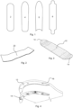
- Figure 1 shows different types of skateboards which may be manufactured with the method and system of the present invention.
- Reference number 2 denotes a street skateboard, reference number 4 a park or transition skateboard, reference number 6 a longboard and reference number 8 a drop through longboard.
- the size of a skateboard may vary between 15 to 30 cm in width and 70 to 150 cm in length.
- the present invention is especially useful for kicktail concave skateboards 10, the basic shape of which is shown in Figure 3 . This means that the skateboard has an upwardly inclined end portion and a concave riding portion.
- the skateboard 10 is also provided with fittings 14. As mentioned above in the background the fittings 14 are used to protected the front and the rear of the skateboard when performing an ollie.
- FIG 4 an enlarged view of the rear end of the skateboard is shown.
- the fitting 14 is shown in a demounted state and a corresponding recess 12 into which the fitting is to be inserted is also clearly shown.
- a recess 12 may be provided both on the upper and the lower side of the skateboard depending on the shape of the fitting. In such a case the fitting would be more U-shaped, such as shown in for example EP 1 156 858B1 , which discloses several types of fittings.
- holes 16 provided in the recess 12, such that the fitting may be screwed onto the recess 12 of the skateboard.
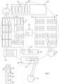
- the system comprises a loading area 40, a handling robot 50, a first printing cell 43, a second printing cell 45, two printing robots 60, a visual system 47, a scanning area 46, a machining area 48, a machining robot 70, a tool storing area 80 and an output area 44.
- the all the robots in the system are computer controlled and may be programmed in many different ways in order to perform the method steps according to the present invention. It is believed to be within the ability of a person skilled in the art to perform such programming in light of what is described in the present disclosure.
- loading areas 40 There may be one or more loading areas 40 depending on the desired production capacity of the system.
- pallets provided with blanks 20 are entering into the manufacturing cell, the main area of which is shown with dotted lines.
- the pallets may be arranged in a carousel containing eight pallets with different types of blanks for producing different types of skateboards. The carousel will rotate in a circle until the correct pallet of blanks 20 is reached, i.e. the type of blank 20 of which the skateboard deck will be manufactured from.
- the handling robot 50 may be a six-axial robot and is used for moving the blanks 20 between different areas in the manufacturing cell, i.e. to and from the loading area, the first and second printing area 43 and 45, the scanning area 46, the machining area 48 and the output area 44.
- the handling robot 50 may be equipped with a laser vision system 47 for scanning the pallets of uncut skateboard blanks in order to indentify the blank which is to be used to manufacture next skateboard body 10.
- the vision system 47 is used for creating a three dimensional virtual image of said blank, which virtual image will be used later on when cutting, printing and/or milling the blank.
- the vision system 47 is instead provided in the scanning area 46 and the handling robot 50 is used to transport the blank 20 or when applicable the skateboard body 10 to and from the scanning area 46.
- a blank 20 is an unprocessed piece and a skateboard body or board body is the blank after all machining steps, such as milling, drilling, sanding and finishing have been performed on the blank.
- the first and second printing area 43 and 45 respectively, may each be divided into two zones having 12 places each for receiving a blank 20 or a skateboard body 10.
- the printing areas 43 and 45 are provided with fixtures 42 adapted to receive and hold the blanks 20 or the skateboard bodies during a printing process to be described below.
- the printing areas 43 and 45 are each served by a printing robot 60.
- the machining robot 70 is also a six-axis robot and is used for machining the blank 20 into a skateboard body 10. The machining is performed in the machining area 48. Since the machining robot 70 is configured to perform different machining operations, such as drilling, milling, sanding and finishing the tool storing area 80 is provided within the reach of the machining robot 70. The tool storing area 80 stores different tools 82-88.
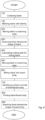
- Figure 6 is a flow chart showing the method according to the present invention, with optional steps marked with dotted lines. It is to be understood that the present invention is directed towards the manufacturing of a board body 10 from a blank having a indefinite shape.
- the board body nay be a skateboard body with a recess 12 at a front and/or at a rear of said body and each recess 12 is adapted to receive a fitting 14 as mentioned above.
- the method starts with step 100, in which the handling robot 50 collects the blank 20 from the loading area 40.
- each blank has a unique and individual shape which has to be known by the system in order for properly machining the blank 20 into a skateboard body.
- the handling robot 50 may be provided with a visual system 47 in order to identify a suitable blank for the next board body 10 to be produced. If the handling robot 50 does not have a vision system 47 the handling robot 50 may instead move, in step 200, the blank 20 to the scanning area 46 and use the vision system 47 provided at this scanning area 46.
- step 300 the shape of the blank 20 is scanned in three dimensions by means of the vision system 47 in order to create a three dimensional virtual image of the blank 20.
- the image is stored for later use.
- the scanning area 46, where the blank is scanned may by the area around the handling robot 50 if the vision system is provided on the handling robot 50.
- the handling robot 50 marks, in step 150, the blank 20 with a unique identity and other information.
- Such information may for example be the name of the client ordering the skateboard, the laminate construction, the shape number, the surface number, the length, the width, the wheelbase, the nose length, the tail length, the nose TIP number, the tail TIP number, the date and time of manufacturing.
- Step 150 is an optional step.
- this data will be used for calculating, in step 400, a three dimensional cutting path for milling the blank 20 into the skateboard body.
- the handling robot 50 moves the blank 20 to the machining area 48 in which the machining robot 70 mills, in step 600, the blank 20 into the board body including said at least one recess 12. If the machining robot 70 needs to change tools 82-88 or replace a worn out tool the machining robot 70 moves to the tool storing area 80 and changes tool.
- steps 100-600 it is possible to manufacture a skateboard body 10 from a blank 20 with high accuracy and efficiency. This is due to the fact that each individual shape of the blank is recognized and taking into account when producing the skateboard body.
- the end user i.e. the rider of the any board may customize his on board body by selecting different parameters when ordering his board. All this may be done without the reprogramming the machining robot 70 for each produce board.
- the machining robot 70 may use the same Computer-Aided Manufacturing, CAM, file which is capable to use the input from the vision system 47, i.e. the shape of the blank 20.
- User selected parameters are also used for calculating the three dimensional cutting path for the machining robot 70.
- the system may as an option also provide for printing an image onto the board body.
- the printing is performed in either the first or the second printing area 43 and 45.
- the reason why two printing areas are used in this exemplary embodiment is that it will increase the manufacturing capacity; when one printing area is occupied with printing the blanks or board bodies by means of the printing robot 60, the other printing area may be unloaded and then loaded with new pieces by the handling robot 50. It is of course also possible to use one or more than two printing areas depending on the desired capacity of the system.
- the printing operation may be performed either before the blank 20 is machined or after the blank has been machined into the board body.
- the printing operation starts with identifying, in step 700, the surface normals of the blank 20 by using the stored virtual image, and then in step 800 printing an image onto the blank, by means of the printing robot 60. This is done by aligning a printing head of the printing robot 60 based on the identified surface normals such that said printing head is carried parallel to the surface of the blank 20 during the printing of the image printing.
- step 900 scanning of the shape of the skateboard body 10 in three dimensions by means of the vision system 47 is performed and a virtual image of said board body 10 is stored in a memory. Thereafter the same steps as above for printing the blank 20 are performed.
- step 700 the surface normals of the board body are identified using the new virtual image and then the image is printed in a corresponding way as for the blank.
Landscapes
- Engineering & Computer Science (AREA)
- Life Sciences & Earth Sciences (AREA)
- Manufacturing & Machinery (AREA)
- Wood Science & Technology (AREA)
- Forests & Forestry (AREA)
- Physics & Mathematics (AREA)
- General Physics & Mathematics (AREA)
- Automation & Control Theory (AREA)
- Mechanical Engineering (AREA)
- Human Computer Interaction (AREA)
- Numerical Control (AREA)
- Motorcycle And Bicycle Frame (AREA)
- Manufacture Or Reproduction Of Printing Formes (AREA)
- Image Processing (AREA)
- Diaphragms For Electromechanical Transducers (AREA)
Claims (14)
- Verfahren zur Herstellung eines Board-Körpers (10) aus einem Rohling (20), wobei der Rohling (20) eine im Wesentlichen rechteckige dreidimensionale konkave Form hat, wobei das Verfahren die folgenden Schritte umfasst:Aufnehmen (100) des Rohlings (20), der die im Wesentlichen rechteckige dreidimensionale konkave Form hat, mittels eines Umladeroboters (50) aus einem Ladebereich (40),Bewegen (200) des Rohlings (20) zu einem Abtastbereich (46),Abtasten (300) der im Wesentlichen rechteckigen dreidimensionalen konkaven Form des Rohlings (20) in drei Dimensionen mittels eines Sichtprüfsystems (47), wobei das Abtasten (300) ein dreidimensionales virtuelles Bild des Rohlings (20) erzeugt;Speichern des dreidimensionalen virtuellen Bilds des Rohlings (20) in einem Speicher;Berechnen (400) eines dreidimensionalen Schneidpfads zum Fräsen des Rohlings (20) zu einem Board-Körper (10) auf der Basis des dreidimensionalen virtuellen Bilds des Rohlings (20) und der vom Benutzer ausgewählten Parameter;Bewegen (500) des Rohlings (20) zu einem Bearbeitungsbereich (48) mittels des Umladeroboters (50); undFräsen (600) des Rohlings (20) längs des berechneten dreidimensionalen Schneidpfads mittels eines Bearbeitungsroboters (70), der konfiguriert ist, einen Fräsbearbeitungsbetrieb auszuführen, zu dem Board-Körper (10).
- Verfahren nach Anspruch 1, das ferner den folgenden Schritt umfasst:
Fräsen (600) einer Aussparung (12) in den Board-Körper (10) an einer Vorderseite und/oder einer Rückseite des Körpers mittels des Bearbeitungsroboters (70), wobei jede Aussparung (12) ausgelegt ist, einen Beschlag (14) aufzunehmen. - Verfahren nach Anspruch 1 oder 2, das ferner die folgenden Schritte umfasst:Identifizieren (700) von Oberflächensenkrechten des Rohlings (20) unter Verwendung des dreidimensionalen virtuellen Bilds, undDrucken (800) eines Bilds auf den Rohling (20) mittels eines Druckroboters (60) durch Ausrichten eines Druckkopfs des Druckroboters (60) auf der Basis der identifizierten Oberflächensenkrechten, so dass der Druckkopf während des Druckens parallel zur Oberfläche des Rohlings (20) geführt wird.
- Verfahren nach Anspruch 1 oder 2, das ferner die folgenden Schritte umfasst:Abtasten (900) der Form des Board-Körpers (10) in drei Dimensionen mittels des Sichtprüfsystems (47) und Speichern des dreidimensionalen virtuellen Bilds des Board-Körpers (10) in einem Speicher,Identifizieren (700) von Oberflächensenkrechten des Board-Körpers (10) unter Verwendung des dreidimensionalen virtuellen Bilds, undDrucken (800) eines Bilds auf den Board-Körper (10) mittels eines Druckroboters (60) durch Ausrichten eines Druckkopfs des Druckroboters (60) auf der Basis der identifizierten Oberflächensenkrechten, so dass der Druckkopf während des Druckens parallel zur Oberfläche des Board-Körpers (10) geführt wird.
- Verfahren nach einem der vorhergehenden Ansprüche, das ferner den folgenden Schritt umfasst:
Markieren (150) des Rohlings mit einer eindeutigen Kennung. - Verfahren nach einem der vorhergehenden Ansprüche, wobei der Bearbeitungsroboter (70) ein sechsachsiger Roboter ist.
- Verfahren nach einem der Ansprüche 1-6, wobei der Board-Körper (10) ein Skateboard, ein Wakeboard, ein Snowboard, ein Skimboard oder ein Snowskate ist.
- System zur Herstellung eines Board-Körpers (10) aus einem Rohling (20), wobei der Rohling (20) eine im Wesentlichen rechteckige dreidimensionale konkave Form hat, wobei das System einen Ladebereich (40), einen Umladeroboter (50), einen Abtastbereich (46), ein Sichtprüfsystem (47), einen Bearbeitungsbereich (48) und einen Bearbeitungsroboter (70), der konfiguriert ist, einen Fräsbearbeitungsbetrieb auszuführen, umfasst, und wobei das System konfiguriert ist, die folgenden Schritte auszuführen:Aufnehmen eines Rohlings (20) mit der im Wesentlichen rechteckigen dreidimensionalen konkaven Form mittels des Umladeroboters (50) aus dem Ladebereich (40),Bewegen des Rohlings zum Abtastbereich (46),Abtasten der im Wesentlichen rechteckigen dreidimensionalen konkaven Form des Rohlings (20) in drei Dimensionen mittels des Sichtprüfsystems (46), wobei das Abtasten ein dreidimensionales virtuelles Bild des Rohlings (20) erzeugt;Speichern des dreidimensionalen virtuellen Bilds des Rohlings (20) in einem Speicher;Berechnen eines dreidimensionalen Schneidpfads zum Fräsen des Rohlings (20) zum Board-Körper (10) auf der Basis des dreidimensionalen virtuellen Bilds des Rohlings (20) und der vom Benutzer ausgewählten Parameter;Bewegen des Rohlings (20) zum Bearbeitungsbereich (48) mittels des Umladeroboters (50);
undFräsen des Rohlings (20) längs des berechneten dreidimensionalen Schneidpfads mittels des Bearbeitungsroboters (70) zum Board-Körper (10). - System nach Anspruch 8, das ferner konfiguriert ist, den folgenden Schritt auszuführen:
Fräsen einer Aussparung (12) in den Board-Körper (10) an einer Vorderseite und/oder an einer Rückseite des Körpers mittels des Bearbeitungsroboters (70), wobei jede Aussparung (12) ausgelegt ist, einen Beschlag (14) aufzunehmen. - System nach Anspruch 8 oder 9, das ferner einen Druckroboter (60) umfasst und ferner konfiguriert ist, die folgenden Schritte auszuführen:Identifizieren von Oberflächensenkrechten des Rohlings (20) unter Verwendung des dreidimensionalen virtuellen Bilds, undDrucken eines Bilds auf den Rohling (20) mittels des Druckroboters (60) durch Ausrichten eines Druckkopfs des Druckroboters (60) auf der Basis der identifizierten Oberflächensenkrechten, so dass der Druckkopf beim Drucken parallel zur Oberfläche des Rohlings (20) geführt wird.
- System nach Anspruch 8 oder 9, das ferner einen Druckroboter (60) umfasst und ferner konfiguriert ist, die folgenden Schritte auszuführen:Abtasten der Form des Board-Körpers (10) in drei Dimensionen mittels des Sichtprüfsystems (47) und Speichern eines dreidimensionalen virtuellen Bilds des Board-Körpers (10) in einem Speicher,Identifizieren von Oberflächensenkrechten des Board-Körpers (10) unter Verwendung des dreidimensionalen virtuellen Bilds, undDrucken eines Bilds auf den Board-Körper (10) mittels des Druckroboters (60) durch Ausrichten eines Druckkopfs des Druckroboters (60) auf der Basis der identifizierten Oberflächensenkrechten, so dass der Druckkopf beim Drucken parallel zur Oberfläche des Board-Körpers (10) geführt wird.
- System nach einem der Ansprüche 8-11, das ferner einen Laser umfasst, der am Umladeroboter (50) angeordnet ist und konfiguriert ist, den folgenden Schritt auszuführen:
Markieren des Rohlings mit einer eindeutigen Kennung. - System nach einem der Ansprüche 8-12, wobei der Bearbeitungsroboter (70) ein sechsachsiger Roboter ist.
- System nach einem der Ansprüche 8-13, wobei der Board-Körper (10) ein Skateboard, ein Wakeboard, ein Snowboard, ein Skimboard oder ein Snowskate ist.
Applications Claiming Priority (2)
| Application Number | Priority Date | Filing Date | Title |
|---|---|---|---|
| SE1450063 | 2014-01-23 | ||
| PCT/SE2015/050059 WO2015112078A1 (en) | 2014-01-23 | 2015-01-22 | System and method for manufacturing a board body |
Publications (4)
| Publication Number | Publication Date |
|---|---|
| EP3096846A1 EP3096846A1 (de) | 2016-11-30 |
| EP3096846A4 EP3096846A4 (de) | 2017-10-25 |
| EP3096846C0 EP3096846C0 (de) | 2023-06-07 |
| EP3096846B1 true EP3096846B1 (de) | 2023-06-07 |
Family
ID=53681744
Family Applications (1)
| Application Number | Title | Priority Date | Filing Date |
|---|---|---|---|
| EP15740337.9A Active EP3096846B1 (de) | 2014-01-23 | 2015-01-22 | System und verfahren zur herstellung eines brettkörpers |
Country Status (8)
| Country | Link |
|---|---|
| US (1) | US10139814B2 (de) |
| EP (1) | EP3096846B1 (de) |
| JP (1) | JP6576354B2 (de) |
| CN (1) | CN106163622B (de) |
| BR (1) | BR112016016941A2 (de) |
| ES (1) | ES2949171T3 (de) |
| MX (1) | MX387708B (de) |
| WO (1) | WO2015112078A1 (de) |
Families Citing this family (4)
| Publication number | Priority date | Publication date | Assignee | Title |
|---|---|---|---|---|
| CN108274092B (zh) * | 2017-12-12 | 2020-08-21 | 北京石油化工学院 | 基于三维视觉与模型匹配的坡口自动切割系统及切割方法 |
| US10137357B1 (en) * | 2018-02-02 | 2018-11-27 | Lithe Industries, Llc | Skateboard decks and methods for constructing skateboard decks |
| CN108673693B (zh) * | 2018-05-18 | 2021-01-15 | 闫星佐 | 一种圆木屋制造方法 |
| WO2024238995A1 (en) * | 2023-05-17 | 2024-11-21 | Botbuilt, Inc., | Systems and methods for the automated cutting of lumber |
Citations (2)
| Publication number | Priority date | Publication date | Assignee | Title |
|---|---|---|---|---|
| WO2000047365A2 (en) * | 1999-02-08 | 2000-08-17 | Oy Robotic Technology Systems Finland Ltd | Machining workpieces |
| JP2007152502A (ja) * | 2005-12-06 | 2007-06-21 | Hokkaido | 自動加工システム |
Family Cites Families (71)
| Publication number | Priority date | Publication date | Assignee | Title |
|---|---|---|---|---|
| US3481619A (en) | 1967-07-13 | 1969-12-02 | Milton A Powers | Skim board |
| US4101405A (en) * | 1971-02-19 | 1978-07-18 | Inoue-Japax Research (Ijr) Inc. | Shaping apparatus |
| AT328932B (de) * | 1972-09-08 | 1976-04-12 | Smolka & Co Wiener Metall | Skibindung |
| US4268949A (en) * | 1979-10-04 | 1981-05-26 | Makino Milling Machine Co., Ltd. | Tracing milling machine |
| JPS5868112A (ja) * | 1981-10-16 | 1983-04-22 | Inoue Japax Res Inc | コンピュータ数値制御方法 |
| US4907164A (en) * | 1988-09-26 | 1990-03-06 | General Electric Company | Automatically optimized NC tool path generation for machining |
| DE4102721A1 (de) * | 1991-01-30 | 1992-08-06 | Rosenthal Ag | Verfahren und vorrichtung zur erzeugung einer sollkontur an einem werkstueck |
| US5377116A (en) * | 1991-07-01 | 1994-12-27 | Valenite Inc. | Method and system for designing a cutting tool |
| JPH08138078A (ja) * | 1994-11-09 | 1996-05-31 | Toshiba Medical Eng Co Ltd | 画像処理装置 |
| US6862023B1 (en) * | 1995-08-18 | 2005-03-01 | Mohammad Salim Shaikh | Fully integrated machinable profile based parametric solid modeler |
| GB9717656D0 (en) * | 1997-08-20 | 1997-10-22 | Videologic Ltd | Shading three dimensional images |
| US6059307A (en) * | 1997-10-28 | 2000-05-09 | Western; Michael W. | Skateboard deck and method for making the same |
| JPH11207514A (ja) * | 1998-01-27 | 1999-08-03 | Toshiba Mach Co Ltd | 加工方法および加工機械 |
| US5974168A (en) * | 1998-04-16 | 1999-10-26 | International Business Machines Corporation | Acquiring bump maps from curved objects |
| SE9900975L (sv) * | 1998-11-16 | 2000-05-17 | Becket Colon | Skateboard |
| JP2001166810A (ja) * | 1999-02-19 | 2001-06-22 | Sanyo Electric Co Ltd | 立体モデル提供装置及び方法 |
| US6237486B1 (en) * | 2000-02-15 | 2001-05-29 | Gregory S. Firth | Screen printing apparatus and method for curved laminated skateboards |
| US6674918B1 (en) * | 2000-02-16 | 2004-01-06 | Microsoft Corporation | Image synthesis by illuminating a virtual deviation-mapped surface |
| US6956569B1 (en) * | 2000-03-30 | 2005-10-18 | Nec Corporation | Method for matching a two dimensional image to one of a plurality of three dimensional candidate models contained in a database |
| IT1320972B1 (it) * | 2000-04-04 | 2003-12-18 | Centauro S P A | Metodo per il taglio di pezzi in legno ed assimilabili, e relativaapparecchiatura attuante tale metodo. |
| US6549819B1 (en) * | 2000-06-13 | 2003-04-15 | Larry Dale Danduran | Method of producing a three-dimensional image |
| US6865442B1 (en) * | 2000-10-24 | 2005-03-08 | Stephen J. Jared | Method of producing orthotic device utilizing mill path about perpendicular axis |
| CN1318929C (zh) * | 2000-11-13 | 2007-05-30 | 西门子公司 | 重构表面的方法和系统 |
| US20020128742A1 (en) * | 2001-03-12 | 2002-09-12 | Zieverink Robert M. | Accurate portraits |
| US7261564B2 (en) * | 2001-04-03 | 2007-08-28 | Sutula Jr Daniel P | Hiking staff, ski pole, or boat paddle, with integrated topographical representations of trails and or terrain |
| JP4828086B2 (ja) * | 2001-05-17 | 2011-11-30 | 三菱電機株式会社 | 加工プログラム作成装置 |
| US6929043B2 (en) * | 2001-07-24 | 2005-08-16 | Valley Machine Works Ltd. | Optimized board edger and method of operation thereof |
| US6704611B2 (en) * | 2001-08-21 | 2004-03-09 | Surfware, Inc. | System and method for rough milling |
| DE10144932B4 (de) * | 2001-09-12 | 2014-07-31 | Siemens Aktiengesellschaft | Visualisierung von Werkstücken bei der Simulation von Fräsprozessen |
| FI20011814A7 (fi) * | 2001-09-14 | 2003-03-15 | Jari Ruuttu | Menetelmä tietyn tuotteen hankkimiseksi julkisen tietoverkon, kuten Internetin, kautta |
| US7251347B2 (en) * | 2002-04-09 | 2007-07-31 | The Escher Group, Ltd. | System and method for authentication of a workpiece using three dimensional shape recovery |
| US7618053B2 (en) * | 2002-11-27 | 2009-11-17 | Marker Deutschland Gmbh | Ski boot sole, disengageable ski binding and ski boot base, and combination thereof |
| DE10255499A1 (de) * | 2002-11-27 | 2004-06-09 | Marker Deutschland Gmbh | Auslösbare Skibindung |
| US7069108B2 (en) * | 2002-12-10 | 2006-06-27 | Jostens, Inc. | Automated engraving of a customized jewelry item |
| US20050069682A1 (en) * | 2003-09-30 | 2005-03-31 | Tan Tseng | Custom 3-D Milled Object with Vacuum-Molded 2-D Printout Created from a 3-D Camera |
| US20060003111A1 (en) * | 2004-07-01 | 2006-01-05 | Tan Tseng | System and method for creating a 3D figurine using 2D and 3D image capture |
| DE102004062923A1 (de) * | 2004-12-28 | 2006-07-06 | Hirschmann Laborgeräte GmbH & Co. KG | Vorrichtung zur Förderung von Fluiden, Verfahren zur Herstellung derselben und Pipette mit einer solchen Vorrichtung |
| ITBZ20050005A1 (it) * | 2005-02-22 | 2006-08-23 | Microtec Srl | Procedimento per riconoscere, in un ciclo di lavorazione attuato in successione in una pluralita' di distinte stazioni di lavorazione, l'oggetto da sottoporre di volta in volta alla rispettiva lavorazione. |
| KR20090004843A (ko) * | 2005-11-30 | 2009-01-12 | 이 아이 듀폰 디 네모아 앤드 캄파니 | 개선된 보드 바인딩 |
| US9022412B2 (en) * | 2006-03-17 | 2015-05-05 | William J Ritter | Splitboard bindings |
| FR2905739B1 (fr) * | 2006-09-08 | 2008-11-07 | Airbus France Sas | Assemblage de panneaux et procede de montage d'un assemblage de panneaux |
| EP1905379B1 (de) * | 2006-09-27 | 2009-12-09 | DeguDent GmbH | Verfahren zum Konstruieren eines Verbinders |
| US7347755B1 (en) * | 2007-02-02 | 2008-03-25 | Katzfey Lance J | Sectionalized surfboard |
| US20100274375A1 (en) * | 2007-02-21 | 2010-10-28 | Team-At-Work, Inc. | Method and system for making reliefs and sculptures |
| CN101441781B (zh) * | 2007-11-23 | 2011-02-02 | 鸿富锦精密工业(深圳)有限公司 | 曲面翻面方法 |
| JP5104298B2 (ja) * | 2007-12-27 | 2012-12-19 | 富士通株式会社 | 解析モデル作成装置及び方法並びにプログラム |
| DE102008011312A1 (de) | 2008-02-27 | 2009-09-03 | Ima Klessmann Gmbh | Anlage zum Bearbeiten von plattenförmigen Werkstücken |
| JP4727689B2 (ja) * | 2008-04-28 | 2011-07-20 | 三菱重工業株式会社 | ワーク計測装置、衝突防止装置および工作機械 |
| US8107721B2 (en) * | 2008-05-29 | 2012-01-31 | Mitsubishi Electric Research Laboratories, Inc. | Method and system for determining poses of semi-specular objects |
| US9087355B2 (en) * | 2008-08-22 | 2015-07-21 | Zazzle Inc. | Product customization system and method |
| WO2010022404A1 (en) * | 2008-08-22 | 2010-02-25 | Zazzle.Com, Inc. | Product customization system and method |
| US20100085359A1 (en) * | 2008-10-03 | 2010-04-08 | Microsoft Corporation | Surface normal reconstruction from a single image |
| IT1392373B1 (it) * | 2008-12-19 | 2012-02-28 | Microtec Srl | Metodo per determinare lo schema di taglio per pezzi di legname quali tronchi. |
| WO2010073547A1 (ja) * | 2008-12-25 | 2010-07-01 | パナソニック株式会社 | 画像処理装置及び擬似立体画像生成装置 |
| IT1393471B1 (it) * | 2009-03-09 | 2012-04-20 | Microtec Srl | Metodo per determinare lo schema di taglio per pezzi di legname quali tronchi |
| US8010328B2 (en) * | 2009-05-19 | 2011-08-30 | Mitsubishi Electric Research Laboratories, Inc. | Method for simulating numerically controlled milling using adaptively sampled distance fields |
| US20100332438A1 (en) * | 2009-06-29 | 2010-12-30 | Weyerhaeuser Nr Company | Methods for Predicting Warp of a Wood Product Produced from a Log |
| JP2011016220A (ja) * | 2009-07-09 | 2011-01-27 | Mori Seiki Co Ltd | プログラミング装置 |
| EP2286956A1 (de) * | 2009-08-20 | 2011-02-23 | Siemens Aktiengesellschaft | Automatisches Reparaturverfahren und System |
| CN101817121B (zh) * | 2010-04-15 | 2012-03-28 | 华中科技大学 | 零件与模具的熔积成形复合制造方法及其辅助装置 |
| AU2011267751B2 (en) * | 2010-06-16 | 2014-12-18 | Ultra Electronics Forensic Technology Inc. | Acquisition of 3D topographic images of tool marks using non-linear photometric stereo method |
| US9519396B2 (en) * | 2010-09-28 | 2016-12-13 | Apple Inc. | Systems, methods, and computer-readable media for placing an asset on a three-dimensional model |
| US8867804B2 (en) * | 2010-11-08 | 2014-10-21 | Cranial Technologies, Inc. | Method and apparatus for automatically generating trim lines for cranial remodeling devices |
| US9690282B2 (en) | 2011-02-28 | 2017-06-27 | Solidcam Ltd. | Computerized tool path generation |
| US8844132B2 (en) * | 2011-07-22 | 2014-09-30 | Pratt & Whitney Canada Corp. | Method of machining using an automatic tool path generator adapted to individual blade surfaces on an integrally bladed rotor |
| ES2474242T3 (es) * | 2011-09-15 | 2014-07-08 | Ideko, S. Coop | Procedimiento de medición y alineación de piezas para mecanizado en máquina herramienta |
| US9137511B1 (en) * | 2011-12-15 | 2015-09-15 | Rawles Llc | 3D modeling with depth camera and surface normals |
| US9675868B2 (en) * | 2012-02-08 | 2017-06-13 | Rayzist Photomask, Inc. | Skateboard with engraved grip surface |
| CN104169823B (zh) * | 2012-03-30 | 2018-01-19 | 株式会社牧野铣床制作所 | 工件加工面显示方法、工件加工面显示装置及刀具路径生成装置 |
| US10022833B2 (en) * | 2012-05-03 | 2018-07-17 | Celeritive Technologies, Inc. | High performance multi-axis milling |
| DE112013005198T5 (de) * | 2012-10-30 | 2015-09-10 | Concepts Eti, Inc. | Verfahren, Systeme und Vorrichtungen zur Gestaltung und Herstellung von flankenfräsbaren Bauteilen |
-
2015
- 2015-01-22 WO PCT/SE2015/050059 patent/WO2015112078A1/en not_active Ceased
- 2015-01-22 CN CN201580005563.2A patent/CN106163622B/zh active Active
- 2015-01-22 US US15/112,999 patent/US10139814B2/en active Active
- 2015-01-22 MX MX2016009531A patent/MX387708B/es unknown
- 2015-01-22 EP EP15740337.9A patent/EP3096846B1/de active Active
- 2015-01-22 JP JP2016548237A patent/JP6576354B2/ja active Active
- 2015-01-22 BR BR112016016941A patent/BR112016016941A2/pt not_active Application Discontinuation
- 2015-01-22 ES ES15740337T patent/ES2949171T3/es active Active
Patent Citations (2)
| Publication number | Priority date | Publication date | Assignee | Title |
|---|---|---|---|---|
| WO2000047365A2 (en) * | 1999-02-08 | 2000-08-17 | Oy Robotic Technology Systems Finland Ltd | Machining workpieces |
| JP2007152502A (ja) * | 2005-12-06 | 2007-06-21 | Hokkaido | 自動加工システム |
Also Published As
| Publication number | Publication date |
|---|---|
| JP2017506093A (ja) | 2017-03-02 |
| CN106163622A (zh) | 2016-11-23 |
| MX387708B (es) | 2025-03-18 |
| US20170003678A1 (en) | 2017-01-05 |
| US10139814B2 (en) | 2018-11-27 |
| CN106163622B (zh) | 2018-11-09 |
| EP3096846C0 (de) | 2023-06-07 |
| ES2949171T3 (es) | 2023-09-26 |
| EP3096846A1 (de) | 2016-11-30 |
| BR112016016941A2 (pt) | 2017-08-08 |
| JP6576354B2 (ja) | 2019-09-18 |
| MX2016009531A (es) | 2017-05-10 |
| WO2015112078A1 (en) | 2015-07-30 |
| EP3096846A4 (de) | 2017-10-25 |
Similar Documents
| Publication | Publication Date | Title |
|---|---|---|
| EP3096846B1 (de) | System und verfahren zur herstellung eines brettkörpers | |
| US10583683B1 (en) | Embedded metal card and related methods | |
| US9640486B2 (en) | Ingot marking for solar cell determination | |
| US8596461B2 (en) | Method and means for facilitating material handling | |
| CN102510667A (zh) | 一种无npth孔定位的cnc锣板生产方法 | |
| Wall et al. | Substiports: User-Inserted Ad Hoc Objects as Reusable Structural Support for Unmodified FDM 3D Printers | |
| US20180170660A1 (en) | Packaging for timepiece appliques | |
| JP2016534900A (ja) | 木質材料の自然な湾曲のある縁部を有する木板から作製された曲線縁部を有するエレメントを含む床モジュールの製造方法 | |
| CN107414418A (zh) | 一种单面机上盘菱角的加工工艺 | |
| DE102013102143B4 (de) | Verfahren zur Herstellung von Möbeln | |
| CN107116655B (zh) | 一种小提琴面板的加工方法 | |
| ATE366638T1 (de) | Schleifeinrichtung und verfahren zur erzeugung einer konturspanfläche mit variablem axialspanwinkel | |
| US7721776B2 (en) | Tiles and apparatus, system and method for fabricating tiles and tile patterns | |
| CN112453513B (zh) | 离心压缩机叶轮叶片的加工方法、及叶轮叶片 | |
| US8374424B2 (en) | Method and apparatus for making multiple copies of a mosaic | |
| CN204640375U (zh) | 一种高精度高强度模切刀版 | |
| CN109905966A (zh) | 一种电路板钻靶及裁磨提升产能的方法 | |
| CN106826368A (zh) | 加工系统 | |
| JP6788867B2 (ja) | 床材の製造方法 | |
| WO2007001251A1 (en) | Method for machining a lens and adhesive label useful when machining the lens | |
| Richards et al. | Lug cutting and trimming of the carbon fibre wing panels of the Airbus A400m with portable hand positioned tools | |
| JP2005088042A (ja) | 積層金型の構造及びその製造方法 | |
| CN103302321B (zh) | 圆形菲涅尔花纹加工刀具组合装置、设备及加工工艺 | |
| TW201028295A (en) | Multi-material thin-film rapid prototyping system and method | |
| CN109515054A (zh) | 一种金属雕刻方法 |
Legal Events
| Date | Code | Title | Description |
|---|---|---|---|
| PUAI | Public reference made under article 153(3) epc to a published international application that has entered the european phase |
Free format text: ORIGINAL CODE: 0009012 |
|
| 17P | Request for examination filed |
Effective date: 20160819 |
|
| AK | Designated contracting states |
Kind code of ref document: A1 Designated state(s): AL AT BE BG CH CY CZ DE DK EE ES FI FR GB GR HR HU IE IS IT LI LT LU LV MC MK MT NL NO PL PT RO RS SE SI SK SM TR |
|
| AX | Request for extension of the european patent |
Extension state: BA ME |
|
| DAX | Request for extension of the european patent (deleted) | ||
| A4 | Supplementary search report drawn up and despatched |
Effective date: 20170922 |
|
| RIC1 | Information provided on ipc code assigned before grant |
Ipc: B27M 1/08 20060101ALI20170918BHEP Ipc: A63C 5/12 20060101ALI20170918BHEP Ipc: A63C 17/01 20060101AFI20170918BHEP Ipc: G05B 19/4099 20060101ALI20170918BHEP Ipc: B23Q 15/20 20060101ALI20170918BHEP Ipc: B27K 5/02 20060101ALI20170918BHEP Ipc: G05B 19/42 20060101ALI20170918BHEP Ipc: B23C 3/16 20060101ALI20170918BHEP Ipc: B27M 3/22 20060101ALI20170918BHEP |
|
| STAA | Information on the status of an ep patent application or granted ep patent |
Free format text: STATUS: REQUEST FOR EXAMINATION WAS MADE |
|
| STAA | Information on the status of an ep patent application or granted ep patent |
Free format text: STATUS: EXAMINATION IS IN PROGRESS |
|
| 17Q | First examination report despatched |
Effective date: 20210526 |
|
| 19U | Interruption of proceedings before grant |
Effective date: 20210422 |
|
| 19W | Proceedings resumed before grant after interruption of proceedings |
Effective date: 20221004 |
|
| RAP3 | Party data changed (applicant data changed or rights of an application transferred) |
Owner name: TECHOVATION AB |
|
| GRAP | Despatch of communication of intention to grant a patent |
Free format text: ORIGINAL CODE: EPIDOSNIGR1 |
|
| STAA | Information on the status of an ep patent application or granted ep patent |
Free format text: STATUS: GRANT OF PATENT IS INTENDED |
|
| INTG | Intention to grant announced |
Effective date: 20221125 |
|
| GRAS | Grant fee paid |
Free format text: ORIGINAL CODE: EPIDOSNIGR3 |
|
| GRAA | (expected) grant |
Free format text: ORIGINAL CODE: 0009210 |
|
| STAA | Information on the status of an ep patent application or granted ep patent |
Free format text: STATUS: THE PATENT HAS BEEN GRANTED |
|
| AK | Designated contracting states |
Kind code of ref document: B1 Designated state(s): AL AT BE BG CH CY CZ DE DK EE ES FI FR GB GR HR HU IE IS IT LI LT LU LV MC MK MT NL NO PL PT RO RS SE SI SK SM TR |
|
| REG | Reference to a national code |
Ref country code: GB Ref legal event code: FG4D |
|
| REG | Reference to a national code |
Ref country code: CH Ref legal event code: EP Ref country code: AT Ref legal event code: REF Ref document number: 1573210 Country of ref document: AT Kind code of ref document: T Effective date: 20230615 |
|
| REG | Reference to a national code |
Ref country code: DE Ref legal event code: R096 Ref document number: 602015083878 Country of ref document: DE |
|
| U01 | Request for unitary effect filed |
Effective date: 20230629 |
|
| U07 | Unitary effect registered |
Designated state(s): AT BE BG DE DK EE FI FR IT LT LU LV MT NL PT SE SI Effective date: 20230707 |
|
| REG | Reference to a national code |
Ref country code: LT Ref legal event code: MG9D |
|
| REG | Reference to a national code |
Ref country code: ES Ref legal event code: FG2A Ref document number: 2949171 Country of ref document: ES Kind code of ref document: T3 Effective date: 20230926 |
|
| PG25 | Lapsed in a contracting state [announced via postgrant information from national office to epo] |
Ref country code: NO Free format text: LAPSE BECAUSE OF FAILURE TO SUBMIT A TRANSLATION OF THE DESCRIPTION OR TO PAY THE FEE WITHIN THE PRESCRIBED TIME-LIMIT Effective date: 20230907 |
|
| PG25 | Lapsed in a contracting state [announced via postgrant information from national office to epo] |
Ref country code: RS Free format text: LAPSE BECAUSE OF FAILURE TO SUBMIT A TRANSLATION OF THE DESCRIPTION OR TO PAY THE FEE WITHIN THE PRESCRIBED TIME-LIMIT Effective date: 20230607 Ref country code: HR Free format text: LAPSE BECAUSE OF FAILURE TO SUBMIT A TRANSLATION OF THE DESCRIPTION OR TO PAY THE FEE WITHIN THE PRESCRIBED TIME-LIMIT Effective date: 20230607 Ref country code: GR Free format text: LAPSE BECAUSE OF FAILURE TO SUBMIT A TRANSLATION OF THE DESCRIPTION OR TO PAY THE FEE WITHIN THE PRESCRIBED TIME-LIMIT Effective date: 20230908 |
|
| PG25 | Lapsed in a contracting state [announced via postgrant information from national office to epo] |
Ref country code: SK Free format text: LAPSE BECAUSE OF FAILURE TO SUBMIT A TRANSLATION OF THE DESCRIPTION OR TO PAY THE FEE WITHIN THE PRESCRIBED TIME-LIMIT Effective date: 20230607 |
|
| PG25 | Lapsed in a contracting state [announced via postgrant information from national office to epo] |
Ref country code: IS Free format text: LAPSE BECAUSE OF FAILURE TO SUBMIT A TRANSLATION OF THE DESCRIPTION OR TO PAY THE FEE WITHIN THE PRESCRIBED TIME-LIMIT Effective date: 20231007 |
|
| PG25 | Lapsed in a contracting state [announced via postgrant information from national office to epo] |
Ref country code: SM Free format text: LAPSE BECAUSE OF FAILURE TO SUBMIT A TRANSLATION OF THE DESCRIPTION OR TO PAY THE FEE WITHIN THE PRESCRIBED TIME-LIMIT Effective date: 20230607 Ref country code: SK Free format text: LAPSE BECAUSE OF FAILURE TO SUBMIT A TRANSLATION OF THE DESCRIPTION OR TO PAY THE FEE WITHIN THE PRESCRIBED TIME-LIMIT Effective date: 20230607 Ref country code: RO Free format text: LAPSE BECAUSE OF FAILURE TO SUBMIT A TRANSLATION OF THE DESCRIPTION OR TO PAY THE FEE WITHIN THE PRESCRIBED TIME-LIMIT Effective date: 20230607 Ref country code: IS Free format text: LAPSE BECAUSE OF FAILURE TO SUBMIT A TRANSLATION OF THE DESCRIPTION OR TO PAY THE FEE WITHIN THE PRESCRIBED TIME-LIMIT Effective date: 20231007 Ref country code: CZ Free format text: LAPSE BECAUSE OF FAILURE TO SUBMIT A TRANSLATION OF THE DESCRIPTION OR TO PAY THE FEE WITHIN THE PRESCRIBED TIME-LIMIT Effective date: 20230607 |
|
| U20 | Renewal fee for the european patent with unitary effect paid |
Year of fee payment: 10 Effective date: 20240115 |
|
| PG25 | Lapsed in a contracting state [announced via postgrant information from national office to epo] |
Ref country code: PL Free format text: LAPSE BECAUSE OF FAILURE TO SUBMIT A TRANSLATION OF THE DESCRIPTION OR TO PAY THE FEE WITHIN THE PRESCRIBED TIME-LIMIT Effective date: 20230607 |
|
| REG | Reference to a national code |
Ref country code: DE Ref legal event code: R097 Ref document number: 602015083878 Country of ref document: DE |
|
| PLBE | No opposition filed within time limit |
Free format text: ORIGINAL CODE: 0009261 |
|
| STAA | Information on the status of an ep patent application or granted ep patent |
Free format text: STATUS: NO OPPOSITION FILED WITHIN TIME LIMIT |
|
| 26N | No opposition filed |
Effective date: 20240308 |
|
| PG25 | Lapsed in a contracting state [announced via postgrant information from national office to epo] |
Ref country code: MC Free format text: LAPSE BECAUSE OF FAILURE TO SUBMIT A TRANSLATION OF THE DESCRIPTION OR TO PAY THE FEE WITHIN THE PRESCRIBED TIME-LIMIT Effective date: 20230607 |
|
| PG25 | Lapsed in a contracting state [announced via postgrant information from national office to epo] |
Ref country code: MC Free format text: LAPSE BECAUSE OF FAILURE TO SUBMIT A TRANSLATION OF THE DESCRIPTION OR TO PAY THE FEE WITHIN THE PRESCRIBED TIME-LIMIT Effective date: 20230607 |
|
| REG | Reference to a national code |
Ref country code: CH Ref legal event code: PL |
|
| GBPC | Gb: european patent ceased through non-payment of renewal fee |
Effective date: 20240122 |
|
| PG25 | Lapsed in a contracting state [announced via postgrant information from national office to epo] |
Ref country code: GB Free format text: LAPSE BECAUSE OF NON-PAYMENT OF DUE FEES Effective date: 20240122 |
|
| PG25 | Lapsed in a contracting state [announced via postgrant information from national office to epo] |
Ref country code: CH Free format text: LAPSE BECAUSE OF NON-PAYMENT OF DUE FEES Effective date: 20240131 |
|
| PG25 | Lapsed in a contracting state [announced via postgrant information from national office to epo] |
Ref country code: GB Free format text: LAPSE BECAUSE OF NON-PAYMENT OF DUE FEES Effective date: 20240122 Ref country code: CH Free format text: LAPSE BECAUSE OF NON-PAYMENT OF DUE FEES Effective date: 20240131 |
|
| PG25 | Lapsed in a contracting state [announced via postgrant information from national office to epo] |
Ref country code: IE Free format text: LAPSE BECAUSE OF NON-PAYMENT OF DUE FEES Effective date: 20240122 |
|
| PG25 | Lapsed in a contracting state [announced via postgrant information from national office to epo] |
Ref country code: IE Free format text: LAPSE BECAUSE OF NON-PAYMENT OF DUE FEES Effective date: 20240122 |
|
| U20 | Renewal fee for the european patent with unitary effect paid |
Year of fee payment: 11 Effective date: 20250120 |
|
| PGFP | Annual fee paid to national office [announced via postgrant information from national office to epo] |
Ref country code: ES Payment date: 20250206 Year of fee payment: 11 |
|
| PG25 | Lapsed in a contracting state [announced via postgrant information from national office to epo] |
Ref country code: CY Free format text: LAPSE BECAUSE OF FAILURE TO SUBMIT A TRANSLATION OF THE DESCRIPTION OR TO PAY THE FEE WITHIN THE PRESCRIBED TIME-LIMIT; INVALID AB INITIO Effective date: 20150122 |
|
| PG25 | Lapsed in a contracting state [announced via postgrant information from national office to epo] |
Ref country code: HU Free format text: LAPSE BECAUSE OF FAILURE TO SUBMIT A TRANSLATION OF THE DESCRIPTION OR TO PAY THE FEE WITHIN THE PRESCRIBED TIME-LIMIT; INVALID AB INITIO Effective date: 20150122 |