EP3095993A1 - Procede de fonctionnement d'un gros moteur diesel, utilisation d'un tel procede et gros moteur diesel - Google Patents
Procede de fonctionnement d'un gros moteur diesel, utilisation d'un tel procede et gros moteur diesel Download PDFInfo
- Publication number
- EP3095993A1 EP3095993A1 EP16167076.5A EP16167076A EP3095993A1 EP 3095993 A1 EP3095993 A1 EP 3095993A1 EP 16167076 A EP16167076 A EP 16167076A EP 3095993 A1 EP3095993 A1 EP 3095993A1
- Authority
- EP
- European Patent Office
- Prior art keywords
- gas
- engine
- mode
- large diesel
- diesel engine
- Prior art date
- Legal status (The legal status is an assumption and is not a legal conclusion. Google has not performed a legal analysis and makes no representation as to the accuracy of the status listed.)
- Pending
Links
Images


Classifications
-
- F—MECHANICAL ENGINEERING; LIGHTING; HEATING; WEAPONS; BLASTING
- F02—COMBUSTION ENGINES; HOT-GAS OR COMBUSTION-PRODUCT ENGINE PLANTS
- F02D—CONTROLLING COMBUSTION ENGINES
- F02D41/00—Electrical control of supply of combustible mixture or its constituents
- F02D41/0025—Controlling engines characterised by use of non-liquid fuels, pluralities of fuels, or non-fuel substances added to the combustible mixtures
- F02D41/0027—Controlling engines characterised by use of non-liquid fuels, pluralities of fuels, or non-fuel substances added to the combustible mixtures the fuel being gaseous
-
- F—MECHANICAL ENGINEERING; LIGHTING; HEATING; WEAPONS; BLASTING
- F02—COMBUSTION ENGINES; HOT-GAS OR COMBUSTION-PRODUCT ENGINE PLANTS
- F02D—CONTROLLING COMBUSTION ENGINES
- F02D13/00—Controlling the engine output power by varying inlet or exhaust valve operating characteristics, e.g. timing
- F02D13/02—Controlling the engine output power by varying inlet or exhaust valve operating characteristics, e.g. timing during engine operation
- F02D13/0242—Variable control of the exhaust valves only
-
- F—MECHANICAL ENGINEERING; LIGHTING; HEATING; WEAPONS; BLASTING
- F02—COMBUSTION ENGINES; HOT-GAS OR COMBUSTION-PRODUCT ENGINE PLANTS
- F02B—INTERNAL-COMBUSTION PISTON ENGINES; COMBUSTION ENGINES IN GENERAL
- F02B75/00—Other engines
- F02B75/02—Engines characterised by their cycles, e.g. six-stroke
-
- F—MECHANICAL ENGINEERING; LIGHTING; HEATING; WEAPONS; BLASTING
- F02—COMBUSTION ENGINES; HOT-GAS OR COMBUSTION-PRODUCT ENGINE PLANTS
- F02B—INTERNAL-COMBUSTION PISTON ENGINES; COMBUSTION ENGINES IN GENERAL
- F02B25/00—Engines characterised by using fresh charge for scavenging cylinders
- F02B25/02—Engines characterised by using fresh charge for scavenging cylinders using unidirectional scavenging
- F02B25/04—Engines having ports both in cylinder head and in cylinder wall near bottom of piston stroke
-
- F—MECHANICAL ENGINEERING; LIGHTING; HEATING; WEAPONS; BLASTING
- F02—COMBUSTION ENGINES; HOT-GAS OR COMBUSTION-PRODUCT ENGINE PLANTS
- F02B—INTERNAL-COMBUSTION PISTON ENGINES; COMBUSTION ENGINES IN GENERAL
- F02B3/00—Engines characterised by air compression and subsequent fuel addition
- F02B3/06—Engines characterised by air compression and subsequent fuel addition with compression ignition
-
- F—MECHANICAL ENGINEERING; LIGHTING; HEATING; WEAPONS; BLASTING
- F02—COMBUSTION ENGINES; HOT-GAS OR COMBUSTION-PRODUCT ENGINE PLANTS
- F02B—INTERNAL-COMBUSTION PISTON ENGINES; COMBUSTION ENGINES IN GENERAL
- F02B43/00—Engines characterised by operating on gaseous fuels; Plants including such engines
-
- F—MECHANICAL ENGINEERING; LIGHTING; HEATING; WEAPONS; BLASTING
- F02—COMBUSTION ENGINES; HOT-GAS OR COMBUSTION-PRODUCT ENGINE PLANTS
- F02B—INTERNAL-COMBUSTION PISTON ENGINES; COMBUSTION ENGINES IN GENERAL
- F02B63/00—Adaptations of engines for driving pumps, hand-held tools or electric generators; Portable combinations of engines with engine-driven devices
- F02B63/04—Adaptations of engines for driving pumps, hand-held tools or electric generators; Portable combinations of engines with engine-driven devices for electric generators
-
- F—MECHANICAL ENGINEERING; LIGHTING; HEATING; WEAPONS; BLASTING
- F02—COMBUSTION ENGINES; HOT-GAS OR COMBUSTION-PRODUCT ENGINE PLANTS
- F02B—INTERNAL-COMBUSTION PISTON ENGINES; COMBUSTION ENGINES IN GENERAL
- F02B69/00—Internal-combustion engines convertible into other combustion-engine type, not provided for in F02B11/00; Internal-combustion engines of different types characterised by constructions facilitating use of same main engine-parts in different types
- F02B69/02—Internal-combustion engines convertible into other combustion-engine type, not provided for in F02B11/00; Internal-combustion engines of different types characterised by constructions facilitating use of same main engine-parts in different types for different fuel types, other than engines indifferent to fuel consumed, e.g. convertible from light to heavy fuel
- F02B69/04—Internal-combustion engines convertible into other combustion-engine type, not provided for in F02B11/00; Internal-combustion engines of different types characterised by constructions facilitating use of same main engine-parts in different types for different fuel types, other than engines indifferent to fuel consumed, e.g. convertible from light to heavy fuel for gaseous and non-gaseous fuels
-
- F—MECHANICAL ENGINEERING; LIGHTING; HEATING; WEAPONS; BLASTING
- F02—COMBUSTION ENGINES; HOT-GAS OR COMBUSTION-PRODUCT ENGINE PLANTS
- F02D—CONTROLLING COMBUSTION ENGINES
- F02D13/00—Controlling the engine output power by varying inlet or exhaust valve operating characteristics, e.g. timing
- F02D13/02—Controlling the engine output power by varying inlet or exhaust valve operating characteristics, e.g. timing during engine operation
- F02D13/0242—Variable control of the exhaust valves only
- F02D13/0249—Variable control of the exhaust valves only changing the valve timing only
-
- F—MECHANICAL ENGINEERING; LIGHTING; HEATING; WEAPONS; BLASTING
- F02—COMBUSTION ENGINES; HOT-GAS OR COMBUSTION-PRODUCT ENGINE PLANTS
- F02D—CONTROLLING COMBUSTION ENGINES
- F02D13/00—Controlling the engine output power by varying inlet or exhaust valve operating characteristics, e.g. timing
- F02D13/02—Controlling the engine output power by varying inlet or exhaust valve operating characteristics, e.g. timing during engine operation
- F02D13/028—Controlling the engine output power by varying inlet or exhaust valve operating characteristics, e.g. timing during engine operation for two-stroke engines
- F02D13/0284—Variable control of exhaust valves only
-
- F—MECHANICAL ENGINEERING; LIGHTING; HEATING; WEAPONS; BLASTING
- F02—COMBUSTION ENGINES; HOT-GAS OR COMBUSTION-PRODUCT ENGINE PLANTS
- F02D—CONTROLLING COMBUSTION ENGINES
- F02D19/00—Controlling engines characterised by their use of non-liquid fuels, pluralities of fuels, or non-fuel substances added to the combustible mixtures
- F02D19/06—Controlling engines characterised by their use of non-liquid fuels, pluralities of fuels, or non-fuel substances added to the combustible mixtures peculiar to engines working with pluralities of fuels, e.g. alternatively with light and heavy fuel oil, other than engines indifferent to the fuel consumed
- F02D19/08—Controlling engines characterised by their use of non-liquid fuels, pluralities of fuels, or non-fuel substances added to the combustible mixtures peculiar to engines working with pluralities of fuels, e.g. alternatively with light and heavy fuel oil, other than engines indifferent to the fuel consumed simultaneously using pluralities of fuels
- F02D19/081—Adjusting the fuel composition or mixing ratio; Transitioning from one fuel to the other
-
- F—MECHANICAL ENGINEERING; LIGHTING; HEATING; WEAPONS; BLASTING
- F02—COMBUSTION ENGINES; HOT-GAS OR COMBUSTION-PRODUCT ENGINE PLANTS
- F02D—CONTROLLING COMBUSTION ENGINES
- F02D19/00—Controlling engines characterised by their use of non-liquid fuels, pluralities of fuels, or non-fuel substances added to the combustible mixtures
- F02D19/06—Controlling engines characterised by their use of non-liquid fuels, pluralities of fuels, or non-fuel substances added to the combustible mixtures peculiar to engines working with pluralities of fuels, e.g. alternatively with light and heavy fuel oil, other than engines indifferent to the fuel consumed
- F02D19/08—Controlling engines characterised by their use of non-liquid fuels, pluralities of fuels, or non-fuel substances added to the combustible mixtures peculiar to engines working with pluralities of fuels, e.g. alternatively with light and heavy fuel oil, other than engines indifferent to the fuel consumed simultaneously using pluralities of fuels
- F02D19/10—Controlling engines characterised by their use of non-liquid fuels, pluralities of fuels, or non-fuel substances added to the combustible mixtures peculiar to engines working with pluralities of fuels, e.g. alternatively with light and heavy fuel oil, other than engines indifferent to the fuel consumed simultaneously using pluralities of fuels peculiar to compression-ignition engines in which the main fuel is gaseous
- F02D19/105—Controlling engines characterised by their use of non-liquid fuels, pluralities of fuels, or non-fuel substances added to the combustible mixtures peculiar to engines working with pluralities of fuels, e.g. alternatively with light and heavy fuel oil, other than engines indifferent to the fuel consumed simultaneously using pluralities of fuels peculiar to compression-ignition engines in which the main fuel is gaseous operating in a special mode, e.g. in a liquid fuel only mode for starting
-
- F—MECHANICAL ENGINEERING; LIGHTING; HEATING; WEAPONS; BLASTING
- F02—COMBUSTION ENGINES; HOT-GAS OR COMBUSTION-PRODUCT ENGINE PLANTS
- F02D—CONTROLLING COMBUSTION ENGINES
- F02D41/00—Electrical control of supply of combustible mixture or its constituents
- F02D41/0025—Controlling engines characterised by use of non-liquid fuels, pluralities of fuels, or non-fuel substances added to the combustible mixtures
-
- F—MECHANICAL ENGINEERING; LIGHTING; HEATING; WEAPONS; BLASTING
- F02—COMBUSTION ENGINES; HOT-GAS OR COMBUSTION-PRODUCT ENGINE PLANTS
- F02D—CONTROLLING COMBUSTION ENGINES
- F02D41/00—Electrical control of supply of combustible mixture or its constituents
- F02D41/02—Circuit arrangements for generating control signals
- F02D41/04—Introducing corrections for particular operating conditions
-
- B—PERFORMING OPERATIONS; TRANSPORTING
- B63—SHIPS OR OTHER WATERBORNE VESSELS; RELATED EQUIPMENT
- B63H—MARINE PROPULSION OR STEERING
- B63H21/00—Use of propulsion power plant or units on vessels
- B63H21/12—Use of propulsion power plant or units on vessels the vessels being motor-driven
- B63H21/14—Use of propulsion power plant or units on vessels the vessels being motor-driven relating to internal-combustion engines
-
- F—MECHANICAL ENGINEERING; LIGHTING; HEATING; WEAPONS; BLASTING
- F02—COMBUSTION ENGINES; HOT-GAS OR COMBUSTION-PRODUCT ENGINE PLANTS
- F02B—INTERNAL-COMBUSTION PISTON ENGINES; COMBUSTION ENGINES IN GENERAL
- F02B75/00—Other engines
- F02B75/02—Engines characterised by their cycles, e.g. six-stroke
- F02B2075/022—Engines characterised by their cycles, e.g. six-stroke having less than six strokes per cycle
- F02B2075/025—Engines characterised by their cycles, e.g. six-stroke having less than six strokes per cycle two
-
- F—MECHANICAL ENGINEERING; LIGHTING; HEATING; WEAPONS; BLASTING
- F02—COMBUSTION ENGINES; HOT-GAS OR COMBUSTION-PRODUCT ENGINE PLANTS
- F02B—INTERNAL-COMBUSTION PISTON ENGINES; COMBUSTION ENGINES IN GENERAL
- F02B75/00—Other engines
- F02B75/02—Engines characterised by their cycles, e.g. six-stroke
- F02B2075/022—Engines characterised by their cycles, e.g. six-stroke having less than six strokes per cycle
- F02B2075/027—Engines characterised by their cycles, e.g. six-stroke having less than six strokes per cycle four
-
- Y—GENERAL TAGGING OF NEW TECHNOLOGICAL DEVELOPMENTS; GENERAL TAGGING OF CROSS-SECTIONAL TECHNOLOGIES SPANNING OVER SEVERAL SECTIONS OF THE IPC; TECHNICAL SUBJECTS COVERED BY FORMER USPC CROSS-REFERENCE ART COLLECTIONS [XRACs] AND DIGESTS
- Y02—TECHNOLOGIES OR APPLICATIONS FOR MITIGATION OR ADAPTATION AGAINST CLIMATE CHANGE
- Y02T—CLIMATE CHANGE MITIGATION TECHNOLOGIES RELATED TO TRANSPORTATION
- Y02T70/00—Maritime or waterways transport
- Y02T70/50—Measures to reduce greenhouse gas emissions related to the propulsion system
- Y02T70/5218—Less carbon-intensive fuels, e.g. natural gas, biofuels
Definitions
- the invention relates to a method for operating a large diesel engine, a large diesel engine and the use of the method according to the preamble of the independent claim of the respective category.
- Large diesel engines which may be designed as two-stroke or four-stroke engines, for example as longitudinally-scavenged two-stroke large diesel engines, are often used as propulsion units for ships or in stationary operation, e.g. used to drive large generators for generating electrical energy.
- the engines usually run for long periods in continuous operation, which places high demands on the reliability and availability. Therefore, for the operator in particular long maintenance intervals, low wear and an economical handling of the operating materials are central criteria.
- a gas e.g. a natural gas such as LNG (liquefied natural gas), or a gas in the form of an autogas or other suitable for driving an internal combustion engine gas burned while in a liquid mode
- a suitable liquid fuel such as gasoline, diesel, heavy oil or other suitable liquid fuels in the same engine can be burned.
- the engines can be both two-stroke and four-stroke engines and it may be small, medium-sized but also large engines, especially also longitudinally purged two-stroke large diesel engines.
- large diesel engine also means those large engines that can be operated except in diesel mode, which is characterized by the auto-ignition of the fuel, in a Otto operation, which is characterized by the spark ignition of the fuel, or in mixed forms of these two.
- large diesel engine also includes, in particular, the aforementioned dual-fuel engines and those large engines in which the self-ignition of the fuel is used for the spark ignition of another fuel.
- the fuel In liquid mode, the fuel is usually introduced directly into the combustion chamber of the cylinder and burns there according to the principle of auto-ignition.
- the gas mode it is known to mix the gas in the gaseous state with the purging air according to the Otto principle, so as to produce an ignitable mixture in the combustion chamber of the cylinder.
- the ignition of the mixture in the cylinder is usually done by a small amount of liquid at the right moment Fuel is injected into the combustion chamber of the cylinder or in an antechamber, which then leads to the ignition of the air-gas mixture.
- a dual-fuel engine can be switched from gas mode to liquid mode during operation, and vice versa.
- the purge or charge air is usually provided by a turbocharger, which generates a purge or supercharger pressure, which depends on the load of the engine and thus on the power or on the torque or the rotational speed of the engine.
- a turbocharger which generates a purge or supercharger pressure, which depends on the load of the engine and thus on the power or on the torque or the rotational speed of the engine.
- the mass of the air in the cylinder can be calculated and then for the respective required drive torque, which is generated by the engine, or for the desired speed determine a suitable amount of the gaseous fuel, which leads to an optimal combustion process for this operating condition ,
- the correct adjustment of the air-gas ratio is of crucial importance for a low-emission, efficient and economical operation of the engine. If the gas content is too high, the air-gas mixture becomes too rich. The combustion of the mixture takes place too fast or too early, which can lead to knocking of the engine. Since the combustion process is then no longer correctly matched to the piston movement in the cylinder, this also leads among other things to the fact that the combustion partly works against the movement of the piston.
- the object of the invention solving this object are characterized by the features of the independent claim of each category.
- the amount of air that is compressed in the cylinder during a working cycle and made available for combustion can be adjusted in a targeted and controlled manner. In this way it can be ensured that the combustion of the air-gas mixture in the cylinder does not reach the region of too rapid or knocking combustion, and that the combustion of the air-gas mixture in the cylinder does not reach the region in which the mixture too lean, ie the amount of air in the cylinder is too large and it can lead to misfires.
- the correction value is set so that the transient closing angle for the exhaust valve is smaller than in normal gas operation, ie related to the duty cycle closes the Exhaust valve now earlier so that more air in the cylinder is available for compression. As a result, the insufficient charge pressure of the purging air can be compensated. If the currently existing charge pressure of the purge air is too large for an optimal composition of the air-gas mixture, the correction value is set so that the transient closing angle for the exhaust valve is greater than in normal gas operation, ie related to the duty cycle closes the Exhaust valve now later, so a smaller amount of air in the cylinder is ready for compression. As a result, the excessive boost pressure of the purging air can be compensated.
- the large diesel engine is preferably designed as a dual-fuel engine for combustion of a gas and for combustion of a liquid fuel, in particular diesel or heavy oil.
- the method according to the invention thus makes it possible for a dual-fuel engine to be used even in the case of sudden and frequent load changes can still be operated efficiently in gas mode. In the case of the important application example of a large diesel engine as a drive unit of a ship, this means that even in heavy seas or in maneuvering the gas mode can continue to be used efficiently.
- a preferred measure is when the correction value is added to the closing angle in order to determine the transient closing angle, because this represents a particularly simple way of correcting the closing angle.
- the correction value is negative. In practice, it has proven itself when its amount is highest 60 degrees.
- the correction value is positive. In practice, it has proven useful if the correction value is at most 60 degrees.
- the limitation of the supplied gas to an upper limit contributes in particular to the fact that the combustion of the air-gas mixture in the cylinder does not reach the region of too fast or knocking combustion.
- the lack of power due to the limited or reduced gas supply to reach the desired setpoint speed is then generated by introducing in transient mode, in addition to the gas, the predetermined amount of liquid fuel into the cylinder, the combustion of which provides the lack of power.
- the transient mode is initiated manually.
- the operator can activate the transient mode of the engine when heavy swell or maneuvering occurs.
- the transient mode is initiated as a function of at least one of the following parameters: current pressure of the purge air, cylinder pressure, calculated air-to-gas ratio, Knock detector signal, engine speed to load ratio, change in engine speed to load ratio, engine torque, torque change, amount of fuel needed for injection, change in amount of fuel needed for injection.
- current pressure of the purge air cylinder pressure
- calculated air-to-gas ratio Knock detector signal
- engine speed to load ratio change in engine speed to load ratio
- engine torque torque change
- amount of fuel needed for injection change in amount of fuel needed for injection.
- change in amount of fuel needed for injection change in amount of fuel needed for injection.
- the additional amount of the liquid fuel can be introduced by means of a pilot injection device into the combustion chamber, which is used in the gas mode for igniting the gas.
- the additional amount of the liquid fuel can be introduced by means of a separate injection device into the combustion chamber, which is provided for the transient mode.
- the supply of the gas into the cylinder can also be done on a cylinder head. Also for this gas supply systems are known.
- the gas can be supplied to the purging air before the purging air is introduced into the cylinder or when the purging air is introduced into the cylinder.
- the last-mentioned variant can in particular also be realized in such a way that one or more gas inlet nozzles are provided on one or more webs which separate adjacent scavenging air openings or scavenging air slots from one another.
- a large diesel engine is also proposed, which is operable at least in a gas mode and which is operated according to a method according to the invention.
- the large diesel engine is preferably designed as a dual-fuel engine for combustion of a gas and for combustion of a liquid fuel, in particular diesel or heavy oil.
- a motor control which comprises a control device for initiating and executing the transient mode.
- the use of a method according to the invention for retrofitting a large diesel engine, in particular a duel-fuel engine is proposed. Since the inventive method can be implemented in many cases without major additional equipment expense, it is particularly suitable for retrofitting already existing large diesel engines or retrofit, so this particular efficient in frequent and sudden load changes, for example in heavy seas, efficiently can be operated environmentally friendly.
- this embodiment of the large diesel engine can be operated in a liquid mode in which only a liquid fuel is injected into a combustion chamber of a cylinder.
- the liquid fuel such as heavy oil or diesel oil
- the large diesel engine can also be operated in a gas mode in which serving as a fuel gas, such as natural gas, is brought in the form of an air-gas mixture in the combustion chamber for ignition.
- the large diesel engine operates in gas mode after a low pressure process, ie Gas is introduced into the cylinder in the gaseous state.
- the mixing with the air can take place in the cylinder itself or even before the cylinder.
- the air-gas mixture is externally ignited in the combustion chamber according to the Otto principle. This spark ignition is usually caused by the fact that at a suitable moment a small amount of liquid fuel is introduced into the combustion chamber, which then self-ignites and thereby causes the spark ignition of the air-gas mixture.
- the large diesel engine can be configured both as a four-stroke engine and as a two-stroke engine.
- the large diesel engine is designed as a longitudinally-flushed two-stroke large diesel engine, which operates in liquid mode with a common rail system.
- Fig. 1 shows a highly schematic representation of a cylinder 21 of this embodiment of a large diesel engine, which is generally designated by the reference numeral 20. Inside the cylinder 21, a piston 23 moves in a manner known per se.
- the structure and individual components of the large diesel engine 20, such as the liquid mode injection system, the gas mode gas supply system, the gas exchange system, the exhaust system or the turbocharger system for providing the charge air, and the control and control system for a Large diesel engine are well known in the art both for the design as a two-stroke engine and for the design as a four-stroke engine and therefore need no further explanation. Of these components is in Fig. 1 only one outlet valve 24 is shown because this is sufficient to understand the invention.
- scavenging air slots 22 are provided in the lower region of each cylinder 21 and cylinder liner, which are periodically closed and opened by the movement of the piston 23 in the cylinder 21 so that the turbocharger from under a boost pressure provided purging air can flow through the scavenging air slots in the cylinder, as long as they are open.
- Fig. 1 indicated by the two provided with the reference symbol L arrows.
- the usually centrally arranged exhaust valve 24 is provided, through which the combustion gases can be discharged from the cylinder into an exhaust system 25 after the combustion process.
- a gas supply system is provided (not shown), which comprises at least one gas inlet valve with a gas inlet nozzle.
- the gas inlet nozzle is typically provided in the wall of the cylinder, for example at a height which is approximately midway between the top and bottom dead center of the piston.
- Fig. 1 are additionally indicated on the left side of various crank angle, which characterize the duty cycle of the large diesel engine 20 in a conventional manner.
- the specified crank angle refer to the compression stroke of the piston 23.
- the piston 23 is in the lower dead or reversal point
- the piston 23 is in the upper dead center or reversal point.
- a complete duty cycle comprises 360 °. Starting at 0 ° - in which the piston 23 is in the same position as at 360 °, namely at top dead center - the piston 23 moves down until it reaches the bottom dead center at 180 ° and then moves upward again during the compression stroke until it reaches top dead center at 360 °.
- the piston 23 just in a position corresponding to the crank angle 270 °.
- a complete duty cycle comprises 720 °, as is well known.
- the large diesel engine is the drive unit of a ship.
- the efficiency and low-emission combustion of the air-gas mixture are very sensitive to the ratio of the amount of air and the amount of gas. This ratio is usually expressed by the ⁇ value, which is the ratio of the mass of air available for combustion and the mass of gas used as the fuel.
- the optimum air-to-gas ratio depends, inter alia, on the drive torque to be generated by the engine and thus on the desired speed of the ship. Since large diesel engines are usually connected directly to the ship's propeller, z. For example, in a fixed propeller of any speed a speed of the engine.
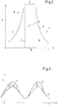
- Fig. 2 shows a schematic representation of an exemplary relationship between the air-to-gas ratio 1 and the engine-generated torque 2, which drives the ship.
- This illustration applies to a particular torque, which corresponds to a certain speed of the ship - or a certain speed of the engine - as the ship moves in essentially calm waters.
- Torque 2 represents the BMEP (Brake Mean Effective Pressure) torque, which is essentially a torque averaged over a duty cycle (a period of piston movement for two-stroke engines and two periods of piston travel for four-stroke engines).
- the air-gas mixture is too rich, that is is to little air in the mixture. Too rich a mixture can lead to various problems, namely that the combustion takes place too fast (fast combustion) or that the engine begins to knock or the mixture in the cylinder then usually by auto-ignition due to the too high content of gas too early (based on the duty cycle) begins to burn (pre-ignition).
- the air-gas mixture is too lean, that is, there is not enough gas - or too much air - for optimal combustion in the combustion chamber available.
- the engine can come in a significant load reduction in an operating condition, which is above the Zündaussetzgrenze 4, where based on the amount of gas too much air in the cylinder 21, the air-gas mixture is therefore too lean.
- an operating state is in Fig. 2 for example, reached at the point C. Due to the out-of-phase response of the turbocharger system, the purge air is provided with too high a boost pressure, so that the air-gas mixture is too lean.
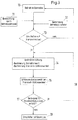
- Fig. 3 shows a schematic representation of a first embodiment of the inventive method.
- the starting point is in a step 10 that the large diesel engine is operated in gas mode. If the ship is now in heavy seas, this state can be detected by observation of the operating personnel 11 and / or on the basis of the evaluation of operating parameters by the engine control or other control devices in step 12. If the heavy load changes caused thereby are judged to be too great, it is decided in a step 13 to switch the large diesel engine into a transient mode.
- the closing angle for closing the exhaust valve 24 in the gas mode is first determined.
- the closing angle is meant the crank angle, in which the exhaust valve 24 is closed during the upward movement of the piston 23.
- the closing angles for the exhaust valve - like the values for other operating parameters - are stored in a matrix whose one dimension is the load of the motor (determined by the generated torque) and whose other dimension is the speed of the motor.
- the correct closing angle for the gas mode can be read off from this matrix for each value pair of load and speed. This is for example 270 °, which is the in Fig. 1 shown position of the piston 23 corresponds.
- the control device Determined in a step 14 the control device then a correction value for the closing angle.
- This correction value can be determined in different ways. In particular, empirical data stored in the control device can also be included in the control value.
- a particularly preferred method for determining the correction value is to use the currently available boost pressure of the purge air for the determination of the correction value.
- This charge pressure is usually detected by measurement in a large diesel engine and is thus available in the control device or can be transmitted to it.
- the determination of the correction value can be determined with the aid of the difference between the instantaneous value of the available charge pressure of the purging air and the required charge pressure of the purging air.
- the required boost pressure for the current operating parameters is stored, for example, in look-up tables or matrices.
- the controller determines a transient closing angle for the exhaust valve by associating the closing angle with the correction value.
- the correction value is added to the closing angle to determine the transient closing angle.
- the controller then causes closure of the exhaust valve 24 at the transient closing angle.
- the correction value is negative, that is, the exhaust valve 24 is already closed at a Transient-Schliesswinkel, which is smaller than the closing angle for the gas mode.
- the correction value is positive, ie the exhaust valve 24 is closed only at a transient closing angle which is greater than the closing angle for the gas mode.
- step 17 is checked continuously or at regular intervals by observations of the operating staff and / or by the determination of the operating parameters, whether the conditions for the activation of the transient mode are still met. If so, the transient mode is maintained as indicated by arrow 18 in FIG Fig. 3 shows, wherein preferably the values for the correction value or the transient-closing angle are checked or updated.
- step 19 it is possible to switch back to the normal gas mode.
- the control device for initiating and executing the transient mode is preferably integrated in the engine control.
- the compression end temperature of the air-gas mixture in the cylinder can increase or decrease. This is usually but not very critical, it should only be avoided that the compression end temperature assumes such high levels that it comes to a self-ignition of the gas-air mixture in the cylinder. This can be ensured, for example, by specifying maximum values for the correction value or its amount in an application-specific manner.
- the second preferred embodiment in the transient mode, in addition to the correction of the closing angle for the exhaust valve to the transient closing angle, the amount of gas supplied as fuel per duty cycle of the large diesel engine is limited by an upper limit, and an addition amount of a liquid fuel is determined in addition to the gas is introduced into the combustion chamber, said additional amount is such that a target value for the speed is realized.
- Fig. 4 shows in a schematic, too Fig. 3 analog representation of the second embodiment of the inventive method.
- the starting point in step 10 is that the large diesel engine is operated in gas mode.
- the state of heavy or sudden load changes which may occur in heavy seas or even in maneuvering operation, can be monitored by the operating personnel 11 and / or by the evaluation of operating parameters by the engine control or other control devices in step 12 be detected. If the strong load changes are judged to be too large, it is decided in step 13 to switch the large diesel engine into transient mode.
- a setpoint for the speed or the torque to be generated by the motor is first determined. This may, for example, be the value which corresponds to the movement of the ship in calm water.
- the control device determines an upper limit for the amount of gas that per cycle of the Large diesel engine is provided as fuel. This upper limit is set so that the purge air available in the cylinder 21 is sufficient to burn the maximum amount of gas determined by the upper limit so that the range of "almost combustion” and / or knocking combustion and / or the area of the "pre-ignition" is avoided, so the air-gas mixture is not too fat.
- the upper limit for the maximum allowable amount of gas to avoid exceeding the knock limit 3 depends on the mass of air present in the cylinder. With known cylinder volume, this mass of air can be determined using the available boost pressure of the scavenging air. Of course, the fluctuations in the boost pressure are taken into account, ie it is advantageously from a minimum boost pressure, which is available in any case. In the determination of a suitable upper limit for the amount of gas can of course also empirical values or other known operating variables of the large diesel engine incorporated.
- a correction value for the closing angle is determined in step 14 '-as described in connection with the first embodiment-and this correction value is linked to the closing angle, preferably additive, in order to determine the transient closing angle for the outlet valve 24.
- the currently available boost pressure of the scavenging air is used for determining the upper limit of the amount of gas.
- the determination of the upper limit for the gas quantity can be determined with the aid of the difference between the instantaneous value of the available charge pressure of the purging air and the required charge pressure of the purging air.
- the required boost pressure for the current operating parameters is stored, for example, in look-up tables or matrices.
- the control device then includes an upper limit for the amount of gas which can be supplied to the cylinder as fuel gas, which is dependent on the boost pressure and possibly also on the transient closing angle, and limits the amount of gas to this upper limit.
- the control device further steps in step 14 ' Additional amount of liquid fuel, which is designed so that it compensates for the difference between the setpoint for the speed or the torque and the achievable with the maximum amount of gas value.
- the controller determines that value for the torque or speed achievable with the maximum amount of gas defined by the upper limit. Then the difference between the setpoint and this value is determined. Subsequently, the amount of liquid fuel needed to make up for this difference is determined.
- the measures of determining the upper limit for the amount of gas, the additional amount of the liquid fuel and the transient closing angle are of course not independent of each other, but it does not pose a major problem to coordinate these measures so as to ensure the best possible operation of the large diesel engine in transient mode is.
- step 15 the exhaust valve 24 is closed at the transient closing angle and the detected amount of gas is introduced into the cylinder in step 15a and made to burn there as in the gas mode.
- the previously determined amount of the liquid fuel is introduced into the cylinder in step 15b and ignites itself there.
- the self-ignition of the liquid fuel can be used for the spark ignition of the air-gas mixture.
- step 17 is checked continuously or at regular intervals by observations of the operating staff and / or by the determination of the operating parameters, whether the conditions for activation Transient mode are still met. If so, the transient mode is maintained as indicated by arrow 18 in FIG Fig. 4
- the values for the upper limit of the amount of gas, for the transient closing angle and for the additional amount of liquid fuel are checked or updated.
- step 19 it is possible to switch back to the normal gas mode.
- the control device for initiating and executing the transient mode is preferably integrated in the engine control.
- the transient mode by combining the combustion of gas with combustion of liquid fuel and adjusting the closing angle for exhaust valve 24, it is ensured that the engine speed setpoint, ie, speed or torque setpoint, is maintained without the combustion of the gas takes place in the region of the "almost combustion" and / or in the region of the knocking.
- the upper limit for the amount of gas ensures that the air-gas mixture in the combustion chamber does not become too rich.
- the misfiring limit 4 (FIG. Fig. 2 ) is exceeded.
- the large diesel engine 20 is always within the tolerance range 6 (FIG. Fig. 2 ) operated.
- a dual-fuel large diesel engine operating in gas mode according to the Otto principle achieve at least approximately the same load change response, such as a working only on the diesel principle large diesel engine, which is operated exclusively with liquid fuel.
- the air-gas mixture is not too fat and not too lean, and on the other hand reacts the belonging to the liquid fuel combustion rate much less sensitive to a low boost pressure of the scavenging air ,
- the running stability of the large diesel engine can be improved and the speed fluctuations are reduced.
- the schematic representation in Fig. 5 illustrates the interaction of the gas combustion and the combustion of the liquid fuel in the transient mode again by way of example.
- the torque T of the large diesel engine is plotted as a function of time t, as can occur in heavy seas.
- the high undulations to which the vessel is then exposed cause an approximately periodic change in the torque T.
- the curve G shows the proportion of the torque caused by the combustion of the gas, the maximum amount of gas being limited the available purging air, taking into account the transient closing angle, is sufficient so that the air-gas mixture does not become too rich.
- the two curves with the reference symbol F, which delimit the hatched areas show the additional contribution to the torque T which is generated by the additional combustion of the liquid fuel.
- the determination of the transient closing angle is particularly suitable. Because by a delayed compared to the gas mode closing the exhaust valve 24, which corresponds to a positive correction value and thus a transient closing angle in this example, which is greater than the closing angle in the gas mode, too much air present in the cylinder 21 can be pushed out through the outlet valve 24 before this is closed.
- the large diesel engine is designed as a dual-fuel engine, can be used for the injection of liquid fuel, the same injector used in liquid mode for the injection of the fuel.
- liquid fuel in the transient mode is introduced into the combustion chamber, which is used in the gas mode for igniting the air-gas mixture.
- a gas supply system can be provided with at least one gas inlet nozzle, which is arranged in the cylinder liner, so that the gas can be introduced into the cylinder and mixed there with the purging air to the ignitable air-gas mixture.
- Another possibility is to supply the gas to the purging air before the purging air is introduced into the cylinder.
- the gas then already mixes outside the interior of the cylinder with the purging air to form an air-gas mixture, which is then introduced into the cylinder, for example through the purging air slots or purging air openings.
- the gas supply into the scavenging air at a point between the outlet of the turbocharger system and the inlet openings in the interior of the cylinder, for example, the scavenge air slots take place.
- the operating parameters which in step 12 ( Fig. 3 and Fig. 4 ) are determined or analyzed to judge in step 13, whether to switch to the transient mode are preferably those parameters that are already present in the engine control, so anyway recorded for operation or during operation of the large diesel engine, or from such Parameters derivable quantities. It is also possible that only one operating parameter is used for the decision to switch to transient mode, or the decision to switch to transient mode is made solely on the basis of the observations by the operating personnel, which can also initiate the transient mode manually.
- one or more of the following quantities are suitable as operating parameters for step 12 or the decision in step 13:
- the inventive method can also be used in particular to retrofit existing large diesel engines, especially dual-fuel engines. Since in such large diesel engines the apparatus requirements for carrying out a method according to the invention are often already met or can be realized with little effort or conversion, it is often possible to make the large diesel engine ready for transient operation by appropriate adjustments or additions in the engine control. This possibility of retrofitting is especially with regard to compliance with the emission limit values a great advantage.
- the measures of determining an upper limit for the amount of gas that is provided as fuel per duty cycle, and the determination of an additional amount of liquid fuel, which is introduced in addition to the gas in the combustion chamber, only in combination with are described the determination of the transient closing angle, so these measures are independent, that is, without changes in the closing angle for the exhaust valve feasible. That is, the second embodiment can also be modified so that the closing angle is not changed in comparison to the gas operation.
Priority Applications (1)
| Application Number | Priority Date | Filing Date | Title |
|---|---|---|---|
| EP16167076.5A EP3095993A1 (fr) | 2015-05-19 | 2016-04-26 | Procede de fonctionnement d'un gros moteur diesel, utilisation d'un tel procede et gros moteur diesel |
Applications Claiming Priority (2)
| Application Number | Priority Date | Filing Date | Title |
|---|---|---|---|
| EP15168103 | 2015-05-19 | ||
| EP16167076.5A EP3095993A1 (fr) | 2015-05-19 | 2016-04-26 | Procede de fonctionnement d'un gros moteur diesel, utilisation d'un tel procede et gros moteur diesel |
Publications (1)
| Publication Number | Publication Date |
|---|---|
| EP3095993A1 true EP3095993A1 (fr) | 2016-11-23 |
Family
ID=53181147
Family Applications (1)
| Application Number | Title | Priority Date | Filing Date |
|---|---|---|---|
| EP16167076.5A Pending EP3095993A1 (fr) | 2015-05-19 | 2016-04-26 | Procede de fonctionnement d'un gros moteur diesel, utilisation d'un tel procede et gros moteur diesel |
Country Status (4)
| Country | Link |
|---|---|
| EP (1) | EP3095993A1 (fr) |
| JP (2) | JP7125245B2 (fr) |
| KR (1) | KR20160136230A (fr) |
| CN (1) | CN106168171A (fr) |
Cited By (1)
| Publication number | Priority date | Publication date | Assignee | Title |
|---|---|---|---|---|
| EP3404237A1 (fr) * | 2017-05-15 | 2018-11-21 | Winterthur Gas & Diesel AG | Procédé de fonctionnement d'un gros moteur diesel ainsi que gros moteur diesel |
Families Citing this family (4)
| Publication number | Priority date | Publication date | Assignee | Title |
|---|---|---|---|---|
| JP7125245B2 (ja) * | 2015-05-19 | 2022-08-24 | ヴィンタートゥール ガス アンド ディーゼル アーゲー | 大型ディーゼル機関を運転する方法、この方法の使用、及び大型ディーゼル機関 |
| CN109339943B (zh) * | 2018-09-01 | 2021-04-20 | 哈尔滨工程大学 | 一种带有滚流燃烧室的天然气缸内直喷双燃料发动机燃烧系统 |
| EP3748144A1 (fr) * | 2019-06-03 | 2020-12-09 | Winterthur Gas & Diesel AG | Procédé de fonctionnement d'un grand moteur ainsi que grand moteur |
| DK180308B1 (en) * | 2019-06-13 | 2020-10-28 | Man Energy Solutions Filial Af Man Energy Solutions Se Tyskland | A large two-stroke uniflow scavenged gaseous fueled engine and method for controlling conditions in combustion chamber |
Citations (5)
| Publication number | Priority date | Publication date | Assignee | Title |
|---|---|---|---|---|
| WO1994029585A1 (fr) * | 1993-06-04 | 1994-12-22 | Man B & W Diesel A/S | Procede permettant de diminuer les contraintes supplementaires dues aux vibrations en torsion affectant un arbre principal de moteur diesel deux temps de forte cylindree |
| DE19809618A1 (de) * | 1998-03-06 | 1999-09-09 | Man B & W Diesel Gmbh | Zweitaktmotor |
| DE102004001825A1 (de) * | 2003-01-14 | 2004-09-02 | Denso Corp., Kariya | Steuervorrichtung für eine Brennkraftmaschine mit innerer Verbrennung |
| WO2010147071A1 (fr) | 2009-06-16 | 2010-12-23 | ヤンマー株式会社 | Dispositif de purification de gaz d'échappement pour moteur à gaz |
| DE102010005814A1 (de) | 2010-01-27 | 2011-07-28 | Bayerische Motoren Werke Aktiengesellschaft, 80809 | Abgasanlage für eine Brennkraftmaschine |
Family Cites Families (26)
| Publication number | Priority date | Publication date | Assignee | Title |
|---|---|---|---|---|
| JPH0639915B2 (ja) * | 1985-04-15 | 1994-05-25 | 三井造船株式会社 | 複式燃料デイ−ゼルエンジンの制御装置 |
| US5575246A (en) * | 1993-09-22 | 1996-11-19 | Yamaha Hatsudoki Kabushiki Kaisha | Operational control device for two-cycle engines |
| JP3375686B2 (ja) * | 1993-09-22 | 2003-02-10 | ヤマハ発動機株式会社 | 2サイクルディーゼルエンジンの運転制御装置 |
| JPH1193710A (ja) * | 1997-09-24 | 1999-04-06 | Nissan Motor Co Ltd | 過給機付2ストロークディーゼル機関の排気弁制御装置 |
| JP2003120386A (ja) | 2001-10-10 | 2003-04-23 | Tokyo Gas Co Ltd | 内燃機関の運転制御方法及び装置 |
| JP3753314B2 (ja) * | 2002-02-14 | 2006-03-08 | 三菱電機株式会社 | 内燃機関の制御用モータの制御装置 |
| JP3991714B2 (ja) * | 2002-03-01 | 2007-10-17 | 国産電機株式会社 | 排気制御バルブ付き2サイクル内燃機関の電子式制御装置 |
| TW200404955A (en) * | 2002-05-30 | 2004-04-01 | Moric Kk | Exhaust timing controller for two-stroke engine |
| JP4052508B2 (ja) | 2002-09-13 | 2008-02-27 | 東京瓦斯株式会社 | デュアルフューエルエンジンの回転制御装置 |
| JP2004263562A (ja) * | 2003-01-14 | 2004-09-24 | Yanmar Co Ltd | 予混合圧縮自着火式内燃機関の制御方法 |
| CA2495501A1 (fr) * | 2004-01-30 | 2005-07-30 | Brp-Rotax Gmbh & Co., Kg. | Commande de sortie d'echappement pour moteur a deux temps |
| JP4281610B2 (ja) | 2004-04-27 | 2009-06-17 | 株式会社豊田自動織機 | 予混合圧縮自着火機関の運転方法及び予混合圧縮自着火機関 |
| JP2006307658A (ja) | 2005-04-26 | 2006-11-09 | Hitachi Ltd | 2ストロークエンジン |
| JP2009203972A (ja) | 2008-02-26 | 2009-09-10 | Shuichi Kitamura | 酸素噴射式内燃機関 |
| JP5448873B2 (ja) | 2010-01-21 | 2014-03-19 | 三菱重工業株式会社 | エンジン排気エネルギー回収装置、これを備える船舶、これを備える発電プラント、エンジン排気エネルギー回収装置の制御装置およびエンジン排気エネルギー回収装置の制御方法 |
| CN103180578B (zh) * | 2010-10-28 | 2016-05-04 | 株式会社Ihi | 二冲程发动机 |
| JP5811539B2 (ja) | 2011-01-24 | 2015-11-11 | 株式会社Ihi | 2サイクルエンジン |
| JP5830309B2 (ja) * | 2011-09-01 | 2015-12-09 | 日本郵船株式会社 | 船舶の推進装置 |
| JP5949183B2 (ja) | 2012-06-06 | 2016-07-06 | 株式会社Ihi | 2ストロークユニフローエンジン |
| JP6003288B2 (ja) * | 2012-06-27 | 2016-10-05 | 株式会社Ihi | ユニフロー掃気式2サイクルエンジン |
| DK177566B1 (en) * | 2012-06-29 | 2013-10-21 | Man Diesel & Turbo Deutschland | An internal combustion engine with control of fuel gas injection pressure |
| JP6028967B2 (ja) * | 2012-07-31 | 2016-11-24 | 国立研究開発法人 海上・港湾・航空技術研究所 | ガスエンジン用燃料噴射装置及びそれを搭載したガスエンジン装置 |
| US9002623B2 (en) * | 2012-08-02 | 2015-04-07 | GM Global Technology Operations LLC | Fully flexible exhaust valve actuator control systems and methods |
| JP6036128B2 (ja) * | 2012-10-03 | 2016-11-30 | 株式会社Ihi | ユニフロー掃気式2サイクルエンジン |
| JP2014098339A (ja) | 2012-11-14 | 2014-05-29 | Mitsubishi Heavy Ind Ltd | ディーゼルエンジンの制御装置、ディーゼルエンジン、及びディーゼルエンジンの制御方法 |
| JP7125245B2 (ja) * | 2015-05-19 | 2022-08-24 | ヴィンタートゥール ガス アンド ディーゼル アーゲー | 大型ディーゼル機関を運転する方法、この方法の使用、及び大型ディーゼル機関 |
-
2016
- 2016-04-25 JP JP2016086693A patent/JP7125245B2/ja active Active
- 2016-04-26 EP EP16167076.5A patent/EP3095993A1/fr active Pending
- 2016-04-26 CN CN201610265092.5A patent/CN106168171A/zh active Pending
- 2016-05-04 KR KR1020160055147A patent/KR20160136230A/ko not_active Application Discontinuation
-
2021
- 2021-03-31 JP JP2021060557A patent/JP2021102961A/ja active Pending
Patent Citations (5)
| Publication number | Priority date | Publication date | Assignee | Title |
|---|---|---|---|---|
| WO1994029585A1 (fr) * | 1993-06-04 | 1994-12-22 | Man B & W Diesel A/S | Procede permettant de diminuer les contraintes supplementaires dues aux vibrations en torsion affectant un arbre principal de moteur diesel deux temps de forte cylindree |
| DE19809618A1 (de) * | 1998-03-06 | 1999-09-09 | Man B & W Diesel Gmbh | Zweitaktmotor |
| DE102004001825A1 (de) * | 2003-01-14 | 2004-09-02 | Denso Corp., Kariya | Steuervorrichtung für eine Brennkraftmaschine mit innerer Verbrennung |
| WO2010147071A1 (fr) | 2009-06-16 | 2010-12-23 | ヤンマー株式会社 | Dispositif de purification de gaz d'échappement pour moteur à gaz |
| DE102010005814A1 (de) | 2010-01-27 | 2011-07-28 | Bayerische Motoren Werke Aktiengesellschaft, 80809 | Abgasanlage für eine Brennkraftmaschine |
Cited By (1)
| Publication number | Priority date | Publication date | Assignee | Title |
|---|---|---|---|---|
| EP3404237A1 (fr) * | 2017-05-15 | 2018-11-21 | Winterthur Gas & Diesel AG | Procédé de fonctionnement d'un gros moteur diesel ainsi que gros moteur diesel |
Also Published As
| Publication number | Publication date |
|---|---|
| JP2016217346A (ja) | 2016-12-22 |
| JP7125245B2 (ja) | 2022-08-24 |
| CN106168171A (zh) | 2016-11-30 |
| KR20160136230A (ko) | 2016-11-29 |
| JP2021102961A (ja) | 2021-07-15 |
Similar Documents
| Publication | Publication Date | Title |
|---|---|---|
| DE102015206074B4 (de) | Brennkraftmaschine und Verfahren zum Betreiben einer Brennkraftmaschine | |
| EP3095993A1 (fr) | Procede de fonctionnement d'un gros moteur diesel, utilisation d'un tel procede et gros moteur diesel | |
| DE112006001271B4 (de) | Direkteinspritzender gasbetriebener Motor und Verfahren zum Steuern des Kraftfahrstoffeinspritzdrucks | |
| DE112015000452B4 (de) | Steuerungsvorrichtung für eine Verbrennungskraftmaschine | |
| EP3267017A1 (fr) | Procédé de fonctionnement d'un moteur diesel de grosse cylindrée dual-fuel et moteur diesel de grosse cylindrée | |
| DE102015202193B4 (de) | Verfahren zum Betreiben einer Brennkraftmaschine sowie Brennkraftmaschine | |
| DE112011105137B4 (de) | Steuersystem für einen Mehrkraftstoff-Verbrennungszylinder | |
| DE112015000460B4 (de) | Steuerungsvorrichtung für eine Verbrennungskraftmaschine | |
| AT516620B1 (de) | Dual-Fuel-Brennkraftmaschine | |
| EP3404237B1 (fr) | Procédé de fonctionnement d'un gros moteur diesel ainsi que gros moteur diesel | |
| EP3872330A1 (fr) | Procédé de fonctionnement d'un grand moteur diesel, ainsi que grand moteur diesel | |
| EP3121428B1 (fr) | Procede de fonctionnement d'un gros moteur diesel, utilisation d'un tel procede et gros moteur diesel | |
| DE102017120512B4 (de) | Verfahren zum Betreiben eines Wasserstoffmotors für ein Kraftfahrzeug | |
| DE2438217A1 (de) | Verfahren und system zur herabsetzung des ausstosses von luftverunreinigungsstoffen bei verbrennungsmotoren | |
| WO2014060071A1 (fr) | Procédé permettant de faire fonctionner un moteur alternatif à combustion interne | |
| WO2020249277A1 (fr) | Procédé pour faire fonctionner un moteur à combustion interne par hydrogène, moteur à combustion interne par hydrogène et véhicule automobile | |
| EP2677141A1 (fr) | Procédé de fonctionnement dýun grand moteur diesel deux temps, ainsi que grand moteur diesel deux temps | |
| EP3693596A1 (fr) | Gros moteur pourvu de ventilateur auxiliaire et procédé de fonctionnement | |
| DE112013001807B4 (de) | Bestimmungsvorrichtung für Maschinenkraftstoffeigenschaften | |
| DE102013108878B4 (de) | Drehmomentbestimmung an einem Verbrennungsmotor mit Mehrfachinjektion | |
| DE102015214930B4 (de) | Verfahren zum Ändern einer Aufteilung auf Saugrohreinspritzung und Direkteinspritzung bei einer Brennkraftmaschine | |
| DE102015211168A1 (de) | Verfahren zum Betreiben einer Brennkraftmaschine und Brennkraftmaschine | |
| EP3748144A1 (fr) | Procédé de fonctionnement d'un grand moteur ainsi que grand moteur | |
| EP3726036A1 (fr) | Procédé de fonctionnement d'un grand moteur ainsi que grand moteur | |
| DE102017205034B4 (de) | Verfahren zum Betreiben einer Brennkraftmaschine und Brennkraftmaschine |
Legal Events
| Date | Code | Title | Description |
|---|---|---|---|
| PUAI | Public reference made under article 153(3) epc to a published international application that has entered the european phase |
Free format text: ORIGINAL CODE: 0009012 |
|
| AK | Designated contracting states |
Kind code of ref document: A1 Designated state(s): AL AT BE BG CH CY CZ DE DK EE ES FI FR GB GR HR HU IE IS IT LI LT LU LV MC MK MT NL NO PL PT RO RS SE SI SK SM TR |
|
| AX | Request for extension of the european patent |
Extension state: BA ME |
|
| STAA | Information on the status of an ep patent application or granted ep patent |
Free format text: STATUS: REQUEST FOR EXAMINATION WAS MADE |
|
| 17P | Request for examination filed |
Effective date: 20170523 |
|
| RBV | Designated contracting states (corrected) |
Designated state(s): AL AT BE BG CH CY CZ DE DK EE ES FI FR GB GR HR HU IE IS IT LI LT LU LV MC MK MT NL NO PL PT RO RS SE SI SK SM TR |
|
| STAA | Information on the status of an ep patent application or granted ep patent |
Free format text: STATUS: EXAMINATION IS IN PROGRESS |
|
| 17Q | First examination report despatched |
Effective date: 20190926 |
|
| STAA | Information on the status of an ep patent application or granted ep patent |
Free format text: STATUS: EXAMINATION IS IN PROGRESS |