EP3095628B1 - Verstärkungs-überbrückungs-einheit für hecktür - Google Patents
Verstärkungs-überbrückungs-einheit für hecktür Download PDFInfo
- Publication number
- EP3095628B1 EP3095628B1 EP16170536.3A EP16170536A EP3095628B1 EP 3095628 B1 EP3095628 B1 EP 3095628B1 EP 16170536 A EP16170536 A EP 16170536A EP 3095628 B1 EP3095628 B1 EP 3095628B1
- Authority
- EP
- European Patent Office
- Prior art keywords
- assembly
- bridge
- panel
- glue line
- housing
- Prior art date
- Legal status (The legal status is an assumption and is not a legal conclusion. Google has not performed a legal analysis and makes no representation as to the accuracy of the status listed.)
- Active
Links
Images

Classifications
-
- B—PERFORMING OPERATIONS; TRANSPORTING
- B60—VEHICLES IN GENERAL
- B60J—WINDOWS, WINDSCREENS, NON-FIXED ROOFS, DOORS, OR SIMILAR DEVICES FOR VEHICLES; REMOVABLE EXTERNAL PROTECTIVE COVERINGS SPECIALLY ADAPTED FOR VEHICLES
- B60J10/00—Sealing arrangements
- B60J10/80—Sealing arrangements specially adapted for opening panels, e.g. doors
-
- B—PERFORMING OPERATIONS; TRANSPORTING
- B62—LAND VEHICLES FOR TRAVELLING OTHERWISE THAN ON RAILS
- B62D—MOTOR VEHICLES; TRAILERS
- B62D25/00—Superstructure or monocoque structure sub-units; Parts or details thereof not otherwise provided for
- B62D25/08—Front or rear portions
- B62D25/10—Bonnets or lids, e.g. for trucks, tractors, busses, work vehicles
- B62D25/105—Bonnets or lids, e.g. for trucks, tractors, busses, work vehicles for motor cars
-
- B—PERFORMING OPERATIONS; TRANSPORTING
- B60—VEHICLES IN GENERAL
- B60J—WINDOWS, WINDSCREENS, NON-FIXED ROOFS, DOORS, OR SIMILAR DEVICES FOR VEHICLES; REMOVABLE EXTERNAL PROTECTIVE COVERINGS SPECIALLY ADAPTED FOR VEHICLES
- B60J1/00—Windows; Windscreens; Accessories therefor
- B60J1/004—Mounting of windows
-
- B—PERFORMING OPERATIONS; TRANSPORTING
- B60—VEHICLES IN GENERAL
- B60J—WINDOWS, WINDSCREENS, NON-FIXED ROOFS, DOORS, OR SIMILAR DEVICES FOR VEHICLES; REMOVABLE EXTERNAL PROTECTIVE COVERINGS SPECIALLY ADAPTED FOR VEHICLES
- B60J1/00—Windows; Windscreens; Accessories therefor
- B60J1/18—Windows; Windscreens; Accessories therefor arranged at the vehicle rear
-
- B—PERFORMING OPERATIONS; TRANSPORTING
- B60—VEHICLES IN GENERAL
- B60J—WINDOWS, WINDSCREENS, NON-FIXED ROOFS, DOORS, OR SIMILAR DEVICES FOR VEHICLES; REMOVABLE EXTERNAL PROTECTIVE COVERINGS SPECIALLY ADAPTED FOR VEHICLES
- B60J10/00—Sealing arrangements
- B60J10/30—Sealing arrangements characterised by the fastening means
- B60J10/34—Sealing arrangements characterised by the fastening means using adhesives
-
- B—PERFORMING OPERATIONS; TRANSPORTING
- B60—VEHICLES IN GENERAL
- B60J—WINDOWS, WINDSCREENS, NON-FIXED ROOFS, DOORS, OR SIMILAR DEVICES FOR VEHICLES; REMOVABLE EXTERNAL PROTECTIVE COVERINGS SPECIALLY ADAPTED FOR VEHICLES
- B60J5/00—Doors
- B60J5/10—Doors arranged at the vehicle rear
- B60J5/101—Doors arranged at the vehicle rear for non-load transporting vehicles, i.e. family cars including vans
- B60J5/107—Doors arranged at the vehicle rear for non-load transporting vehicles, i.e. family cars including vans constructional details, e.g. about door frame, panels, materials used, reinforcements
-
- B—PERFORMING OPERATIONS; TRANSPORTING
- B62—LAND VEHICLES FOR TRAVELLING OTHERWISE THAN ON RAILS
- B62D—MOTOR VEHICLES; TRAILERS
- B62D25/00—Superstructure or monocoque structure sub-units; Parts or details thereof not otherwise provided for
- B62D25/08—Front or rear portions
- B62D25/10—Bonnets or lids, e.g. for trucks, tractors, busses, work vehicles
- B62D25/12—Parts or details thereof
Definitions
- the present invention relates to an assembly intended to be part of a tailgate for a motor vehicle.
- the lining of a boot flap carries a rear window attached to the liner by gluing.
- the bonding must be perfectly watertight to avoid the intrusion of water by the boot flap in the vehicle.
- the present invention is intended to provide an assembly for reinforcing the lining of a boot flap, further maintaining a satisfactory seal between the rear window and the assembly.
- the subject of the invention is an assembly according to claim 1.
- the assembly of the invention makes it possible to stiffen the boot flap of a vehicle, while allowing the glue line between the rear window and the liner and the bridge to be sealed.
- the use of a bridge attached to the liner also allows greater freedom for the design of the trunk lid of a vehicle.
- the terms “upper” or “high”, and “lower” or “low” are defined with respect to a vehicle with a tailgate in a closed position, except when they have a local meaning.
- An orthogonal reference is represented on the figure 1 , in which the “up” or “vertical” direction is designated by the reference Z.
- the terms “front” and “rear” are defined with respect to the direction of movement of the vehicle in the direction designated by the reference X.
- the “lateral” or “horizontal” parts of assembly 1 are relative to the reference Y.
- the terms “inner” and “outer” are defined with respect to a volume included in the motor vehicle, except when they have a meaning local.
- the set 1 represented on the figure 1 comprises a liner 2 and at least one bridge 4 defining together an opening 6 intended to be covered by a rear window 7 of a tailgate.
- this opening 6 is located in the upper part of the lining 2.
- the lining 2 defines a frame 8 forming at least a part of the opening 6.
- the frame 8 of the liner 2 comprises an upper upright 10 which extends substantially in the horizontal direction Y, at least two opposite uprights 12 which extend substantially in the vertical direction Z laterally on the lining 2, and a lower portion 14 extending substantially in a horizontal Y direction.
- the liner 2 may extend in a vertical plane defined by the directions Y and Z, or be inclined relative to this vertical plane. Similarly, it is conceivable that the liner 2 has a left shape, that is to say non-planar.
- the assembly 1 is intended to be fixed by the upper amount 10 on a chassis of the motor vehicle.
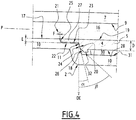
- At least a first line of adhesive 16 extends around the opening 6 on at least a portion of an outer surface 17 of the liner 2 and at least a portion of an outer surface 19 of the bridge 4, as is represented on the Figures 1 to 4 .
- This glue line 16 is preferably continuous.
- the glue line 16 is intended to fix the rear window 7 on the assembly 1 in a sealed manner. As a result, the glue line 16 extends substantially along a left curve P parallel to an inner surface 9 of the rear window 7.
- the glue line 16 advantageously has a width L parallel to the rear window 7 of 22 mm in vision.
- the glue line 16 has a thickness perpendicular to the rear window 7 of 5 mm.
- the glue line 16 is formed by an adhesive having sealing properties and tear resistance varying according to the specifications of the manufacturers.
- the liner 2 is made of plastic by molding, for example polypropylene, for example of the type PP TD 30, PP TD 40 or PP TD 50. It is also conceivable to use thermosetting plastic, composite materials or carbon for form frame 8 of the liner 2.
- the housing 18 has a rim 11 at its periphery.
- the housing 18 is formed in part by the lining 2 at the opposite uprights 12 of the frame 8.
- the opposite uprights 12 of the liner 2 may have a cross section, perpendicular to the first U-shaped glue line 16.
- the housing 18 also has a cross section, perpendicular to the first glue line 16, U-shaped
- U-shape makes it possible in particular to increase the rigidity of the opposite amounts 12.
- Opposite amounts 12 are advantageously formed by molding.
- the housing 18 comprises a bearing surface 20 extending along a plane inclined to a direction of thickness DE.
- the thickness direction DE is substantially perpendicular to the rear window 7.
- the bearing surface 20 locally defines an angle of between 5 ° and 25 °, preferably 15 ° with the thickness direction DE.
- the bearing surface 20 is intended to receive at least a portion of the bridge 4 in support.
- the bridge 4 is stabilized in the housing 18 and / or the play of the bridge in a direction parallel to the left curve P is reduced.
- the bearing surface 20 of the housing 18 may have a rough surface and / or ribs extending perpendicularly to the thickness direction DE, shown in FIG. figure 4 .
- the lining 2 has a notch 22 defining part of the housing 18.
- This notch 22 comprises at least one surface of the liner 2 extending in a plane perpendicular to the thickness direction DE.
- the notch 22 has a width L1 in a direction perpendicular to the glue line 16 and to the thickness direction DE equal to or greater than the width L of the glue line 16.
- the notch 22 has a surface 23 extending parallel to the left curve P, and a curved surface 25, non-perpendicular to the thickness direction DE, and connecting the outer surface 17 of the liner 2 with the surface 23 of the lining 2.
- the notch 22 is formed on the flange 11 of the housing 18.
- the notch 22 is intended to receive a flexible blade 27 of the bridge 4 and therefore comprises a shape complementary to that of the flexible blade 27.
- the flexible blade 27 will be described later.
- the bridge 4 may be made of the same material as the liner, or a material having a higher rigidity.
- the bridge 4 comprises a body 5 of substantially complementary shape to that of the housing 18 defined by the lining 2 and the rear window 7.
- the body 5 has a thickness D in the thickness direction DE of between 2.5 and 3.5 mm, preferably 3 mm.
- the body 5 of the bridge 4 comprises at least one abutment surface 24 partly transverse along the first line of adhesive 16.
- the abutment surface 24 extends in a plane substantially inclined with respect to the thickness direction DE.
- the abutment surface 24 is intended to abut against the bearing surface 20 of the housing 18. Consequently, the abutment surface 24 is advantageously in plane contact with the bearing surface 20 of the housing 18 of the liner 2.
- the abutment surface 24 of the body 5 defines an angle ⁇ of between 5 ° and 25 °, preferably 15 °, with the thickness direction DE.
- the body 5 of the bridge 4 may comprise two opposing abutment surfaces 24 and cooperating with the two bearing surfaces 20 of the housing 18 of the liner 2.
- the two abutment surfaces 24 give the bridge 4 a wedge-shaped shape locally. This form allows the clamping of the spawn 4 in the housing 18 of the upright 12.
- the abutment surface 24 may comprise a rough surface and / or ribs extending perpendicular to the thickness direction DE in the housing 18.
- the bridge 4 is held firmly in the housing 18.
- the thickness direction DE of the bridge 4 is locally, at the housing 18, substantially perpendicular to the left curve P.
- the bridge 4 may optionally comprise an alignment surface 26 adjacent to the abutment surface 24 in the thickness direction DE of the bridge 4.
- This alignment surface 26 of the bridge 4 defines an acute angle with the bearing surface 20 of the housing 18. More specifically, in the example shown, the alignment surface forms an angle ⁇ with the thickness direction DE of between 35 ° and 55 °, preferably 45 °.
- the alignment surface 26 makes it possible to align the bridge 4 when it is inserted into the housing 18.
- the insertion of the bridge 4 into the housing 18 is facilitated during the assembly of the bridge 4 and the liner 2. assembly will be described later.
- the bridge 4 has an inner surface 28 substantially perpendicular to the thickness direction DE.
- the inner surface 28 is rotated in the thickness direction DE towards the interior of the motor vehicle.
- the bridge 4 is for example fixed on the liner 2 by a layer of adhesive 30.
- the adhesive layer 30 is located between a bottom surface 31 of the housing 18 and the inner surface 28 of the body 5 of the liner 2
- the inner surface 28 of the bridge 4 is connected by the adhesive layer 30 to the bottom surface 31 of the housing 18.
- the body 5 of the bridge 4 has a flange 32 projecting from the inner surface 28. This has the effect of blocking a displacement beyond the inner surface 28 of the adhesive layer 30.
- the bridge 4 is for example fixed on the liner 2 by another method of chemical or mechanical fixation, preferably by welding, riveting or screwing.
- the flexible blade 27 of the bridge 4 extends one end of the body 5 of the bridge 4 according to the first glue line 16.
- the flexible blade 27 is located at least in a region of the bridge 4 located under the first line of adhesive 16.
- the flexible blade 27 may also extend over the entire edge of the bridge 4.
- the flexible strip 27 is intended to cooperate with the notch 22 of the liner 2. It is therefore complementary to the notch 22.
- the flexible strip 27 has a thickness E less than the thickness D of the body 5. Thus, the flexible strip 27 is more flexible than the body 5 of the bridge 4.
- the thickness E of the flexible lamella 27 is for example between 1 and 3 mm, preferably about 1.3 mm.
- the thickness E of the flexible lamella 27 depends on the material of the bridge 4.
- the thickness E is chosen according to the desired flexibility. The smaller the thickness E, the greater the flexibility of the flexible lamella 27 increases.
- the strip 27 defines a slot 21 with the notch 22 of the liner 2.
- the shape of the slot 21 is defined by the notch 22 and the strip 20.
- the slot 21 has a width F according to the first glue line 16 included between 0.1 and 1 mm, preferably about 0.2 mm.
- the flexible strip 27 it is possible to create a local alignment in the thickness direction DE of the bridge 4. In this way, the outer surface 19 of the bridge 4 and the outer surface 17 of the liner 2 form a junction between the notch 22 and the strip 27 located in the same plane perpendicular to the thickness direction DE.
- the thickness of the glue line 16 is homogeneous and the sealing of the glue line 16 is maximized.
- the assembly 1 may be located under a second line of glue 34, or several lines of glue.
- the second glue line 34 extends mainly in the portion 14 of the liner 2. For example, it extends on the lower periphery of the liner 2.
- the glue line 34 allows the attachment of a cover panel of the motor vehicle, not shown, covering the assembly 1 at least partially.
- This cover panel of the motor vehicle can be for example plastic. According to one variant, the cover panel of the motor vehicle is made of metallic material or carbon.
- first glue line 16 applies in the same way to the second glue line 34.
- description concerning a first interface between the liner 2 and the bridge 4 locally covered by the first line of glue 16 to wear the rear window 7 applies in the same way to a second interface between the liner 2 and the bridge 4 locally covered by the second line of glue 34 to carry the cover panel of the motor vehicle .
- the bridge 4 is in two or more parts.
- the freedom of form and freedom of style of the opening 6 defined by the set 1 is increased.
- a jumper formed of a single piece gives a greater rigidity to the tailgate a bridge formed of several parts.
- the assembly 1 simplifies the tooling for the manufacture of the liner, for example because it is not necessary to add movement in the tooling.
- the lining 2 is provided. Then, an adhesive layer 30 is applied to the bottom surface 31 of the housing 18. Alternatively, the adhesive layer 30 is applied to the lower surface 28 of the bridge 4.
- At least one bridge 4 is inserted into the housing 18 with its lower surface 28 facing the bottom surface 31 of the housing 18. At the same time, the blade 27 of the bridge 4 is inserted into the notch 22 of the liner 2.
- the alignment surface 26 of the bridge 4 can come into contact with the rim 11 of the housing 18.
- the alignment surface 26 promotes the alignment of the bridge according to the first line of glue 16.
- the flexible strip 27 makes it possible to reduce the depth in the direction of the thickness DE during a docking between bridge 4 and liner 2.
- a first line of glue 16 is applied to the bridge 4 and the liner 2.
- this first glue line 16 extends continuously around the opening 6.
- the glue of the glue line 16 does not infiltrate almost between the flexible lamella 27 and the lining 2.
- the rear window 7 is applied by pressing its inner surface 9 on the first glue line 16 to be fixed on the lining 2 and the bridge 4.
- the flexible blade 27 can deform in the thickness direction DE.
- the thickness of the glue line is substantially homogeneous in the thickness direction DE along the glue line 16.
- a second line of glue 34 is optionally applied to the bridge 4 and the portion 14 of the liner 2.
- This second glue line 34 may comprise for example the same thickness and width as the first line 16.
- the second glue line 34 extends in part at the edge of the portion 14 of the liner 2.
- a cover panel of a motor vehicle (not shown) is fixed by the second glue line 34 on the assembly 1.
- This cover panel of a motor vehicle is preferably made of plastic, but can also be made for example of metal or carbon.
- the second glue line 34 is applied before fixing the rear window 7 to the first glue line 16.
- the outer surface 17 of the liner and the outer surface 19 of the bridge are aligned at the slot 21 in a local plane perpendicular to the thickness direction DE. This alignment guarantees a homogeneous thickness of the adhesive line 16, at least locally at the level of the slot 21.
- the flexibility of the flexible blade 27 can correct this shift so that the upper surface 19 of the bridge and the outer surface 17 of the liner 2 remain aligned at the slit 21.
- the thickness of the first and / or second glue line remains homogeneous at the slit 21.
Landscapes
- Engineering & Computer Science (AREA)
- Mechanical Engineering (AREA)
- Chemical & Material Sciences (AREA)
- Combustion & Propulsion (AREA)
- Transportation (AREA)
- Body Structure For Vehicles (AREA)
- Superstructure Of Vehicle (AREA)
Claims (10)
- Baugruppe (1), die vorgesehen ist, um Teil einer Kofferraumklappe für ein Kraftfahrzeug zu sein, wobei die Baugruppe (1) aufweist:- eine Auskleidung (2) und mindestens einen Steg (4), die eine Öffnung (6) definieren, und- eine erste Klebelinie (16), die vorgesehen ist, um eine Heckscheibe (7) der Kofferraumklappe an der Auskleidung (2) zu befestigen, wobei die Heckscheibe (7) eine Dickenrichtung (DE) definiert,wobei der Steg (4) aufweist: einen Körper (5) und ein Ende, das sich entlang der erste Klebelinie (16) erstreckt, dadurch gekennzeichnet, dass das Ende eine flexible Lamelle (27) ausbildet, die vorgesehen ist, um in einer Aufnahme (18) aufgenommen zu sein, die durch die Auskleidung (2) und die Heckscheibe (7) ausgebildet ist.
- Baugruppe (1) gemäß Anspruch 1, wobei die Aufnahme (18) teilweise durch die Auskleidung (2) ausgebildet ist, wobei die Auskleidung (2) eine Nut (22) aufweist, die die Aufnahme (18) teilweise definiert, wobei die Nut (22) eine Breite (L1) entlang einer Richtung senkrecht zu der Klebelinie (16) und zu der Dickenrichtung (DE) hat, wobei die Breite (L1) größer oder gleich einer Breite (L) der Klebelinie (16) ist.
- Baugruppe (1) gemäß Anspruch 2, wobei die Nut (22) teilweise durch eine Fläche (23) der Auskleidung (2) definiert ist, wobei die Fläche (23) im Wesentlichen senkrecht zu der Dickenrichtung (DE) ist.
- Baugruppe (1) gemäß irgendeinem der Ansprüche 1 bis 3, wobei der Körper (5) eine Anschlagfläche (24) aufweist, die teilweise quer entlang der ersten Klebelinie (16) verläuft, wobei die Anschlagfläche (24) mit der Dickenrichtung (DE) einen Winkel (α) ausbildet, der zwischen 5° und 25° beträgt, vorzugsweise im Wesentlichen gleich 15° ist.
- Baugruppe (1) gemäß irgendeinem der Ansprüche 1 bis 4, wobei der Körper (5) des Stegs (4) eine Ausrichtungsfläche (26) aufweist, die mit der Dickenrichtung (DE) einen Winkel (β) ausbildet, wobei der Winkel (β) zwischen 35° und 55° beträgt, vorzugsweise im Wesentlichen gleich 45° ist.
- Baugruppe (1) gemäß irgendeinem der Ansprüche 1 bis 5, wobei die flexible Lamelle (27) des Stegs (4) eine Dicke (E) entlang der Dickenrichtung (DE) hat, die zwischen 1 und 3 mm und vorzugsweise etwa 1,3 mm beträgt.
- Baugruppe (1) gemäß irgendeinem der Ansprüche 1 bis 6, wobei die flexible Lamelle (27) mit der Nut (22) der Aufnahme (18) einen Schlitz (21) definiert, wobei der Schlitz (21) eine Breite (F) entlang der ersten Klebelinie (16) hat, die zwischen 0,1 mm und 1 mm, vorzugsweise etwa 0,2 mm beträgt.
- Baugruppe (1) gemäß irgendeinem der Ansprüche 1 bis 7, aufweisend eine Klebeschicht (30), die sich auf einer Innenfläche (28) des Körpers (5) des Stegs (4) befindet, wobei der Körper (5) einen Rand (32) aufweist, der von der Innenfläche (28) hervorsteht.
- Baugruppe (1) gemäß irgendeinem der Ansprüche 1 bis 8, wobei die Baugruppe (1) ferner eine zweite Klebelinie (34) aufweist, die sich über dem Steg (4) und der Auskleidung (2) erstreckt, wobei die Auskleidung (2) einen Teil (14) aufweist, der vorgesehen ist, um durch die zweite Klebelinie (34) an einer Abdeckplatte des Kraftfahrzeugs befestigt zu sein.
- Kraftfahrzeug (1), aufweisend eine Kofferraumklappe, die eine Baugruppe (1) gemäß irgendeinem der Ansprüche 1 bis 9 aufweist.
Applications Claiming Priority (1)
| Application Number | Priority Date | Filing Date | Title |
|---|---|---|---|
| FR1554529A FR3036327B1 (fr) | 2015-05-20 | 2015-05-20 | Ensemble doublure-pontet pour volet plastique |
Publications (2)
| Publication Number | Publication Date |
|---|---|
| EP3095628A1 EP3095628A1 (de) | 2016-11-23 |
| EP3095628B1 true EP3095628B1 (de) | 2017-10-11 |
Family
ID=54007836
Family Applications (1)
| Application Number | Title | Priority Date | Filing Date |
|---|---|---|---|
| EP16170536.3A Active EP3095628B1 (de) | 2015-05-20 | 2016-05-20 | Verstärkungs-überbrückungs-einheit für hecktür |
Country Status (5)
| Country | Link |
|---|---|
| US (1) | US10293671B2 (de) |
| EP (1) | EP3095628B1 (de) |
| CN (1) | CN106167052B (de) |
| ES (1) | ES2649214T3 (de) |
| FR (1) | FR3036327B1 (de) |
Families Citing this family (2)
| Publication number | Priority date | Publication date | Assignee | Title |
|---|---|---|---|---|
| CN111376989A (zh) * | 2018-12-28 | 2020-07-07 | 观致汽车有限公司 | 前盖内板及其拼焊分界方法 |
| KR102227136B1 (ko) * | 2019-10-28 | 2021-03-12 | 주식회사 서연이화 | 차량용 테일게이트의 이너패널구조 |
Family Cites Families (10)
| Publication number | Priority date | Publication date | Assignee | Title |
|---|---|---|---|---|
| DE3637622A1 (de) * | 1986-11-05 | 1988-05-19 | Ford Werke Ag | Doppelwandiges karosseriebauteil aus kunststoff fuer kraftfahrzeuge |
| FR2733723B1 (fr) * | 1995-05-05 | 1997-05-30 | Renault | Hayon de fermeture a couvercle additionnel pour carrosserie de vehicule automobile |
| US6607231B2 (en) * | 2001-07-23 | 2003-08-19 | Ford Global Technologies, Inc. | Liftgate with low-liftover liftglass |
| JP4778936B2 (ja) * | 2007-06-22 | 2011-09-21 | 株式会社豊田自動織機 | 自動車におけるピラー部構造 |
| FR2945480B1 (fr) * | 2009-05-18 | 2015-05-15 | Plastic Omnium Cie | Ouvrant de vehicule muni de charniere. |
| EP2644815B1 (de) * | 2009-11-16 | 2018-04-04 | Toyota Jidosha Kabushiki Kaisha | Türstruktur mit obenliegendem Scharnier |
| FR2953770B1 (fr) | 2009-12-16 | 2011-11-25 | Renault Sas | Porte de coffre pour vehicule automobile |
| JP5681015B2 (ja) * | 2011-03-30 | 2015-03-04 | マツダ株式会社 | 車両用リフトゲート構造 |
| CN202319838U (zh) * | 2011-12-02 | 2012-07-11 | 上海同捷科技股份有限公司 | 行李箱内板的防水结构 |
| JP6156300B2 (ja) * | 2014-09-16 | 2017-07-05 | トヨタ自動車株式会社 | 車体構造 |
-
2015
- 2015-05-20 FR FR1554529A patent/FR3036327B1/fr not_active Expired - Fee Related
-
2016
- 2016-05-19 US US15/159,035 patent/US10293671B2/en not_active Expired - Fee Related
- 2016-05-20 CN CN201610341945.9A patent/CN106167052B/zh active Active
- 2016-05-20 EP EP16170536.3A patent/EP3095628B1/de active Active
- 2016-05-20 ES ES16170536.3T patent/ES2649214T3/es active Active
Non-Patent Citations (1)
| Title |
|---|
| None * |
Also Published As
| Publication number | Publication date |
|---|---|
| EP3095628A1 (de) | 2016-11-23 |
| CN106167052B (zh) | 2020-02-18 |
| ES2649214T3 (es) | 2018-01-10 |
| US20160339771A1 (en) | 2016-11-24 |
| CN106167052A (zh) | 2016-11-30 |
| FR3036327A1 (fr) | 2016-11-25 |
| FR3036327B1 (fr) | 2017-05-19 |
| US10293671B2 (en) | 2019-05-21 |
Similar Documents
| Publication | Publication Date | Title |
|---|---|---|
| EP2512850B1 (de) | Heckklappe eines kraftfahrzeuges | |
| EP3224122B1 (de) | Kraftfahrzeugspoiler mit abnehmbarer unterseite | |
| EP3174778B1 (de) | Zweiteiliger kraftfahrzeugspoiler | |
| FR2962073A1 (fr) | Joint d'etancheite de porte | |
| WO2017089702A1 (fr) | Vitrage a profile integre | |
| FR2968631A1 (fr) | Sous-ensemble, notamment de vehicule, a peau externe et structure interne fixees par cordon de colle | |
| EP2121362B1 (de) | Verfahren zur anordnung einer glasur auf ihrem halter durch verkleben, sowie mittel zur durchführung des verfahrens | |
| EP3095628B1 (de) | Verstärkungs-überbrückungs-einheit für hecktür | |
| FR2995861A1 (fr) | Habillage interieur structurel pour porte laterale de vehicule et porte laterale ainsi equipee | |
| EP3060454B1 (de) | Verfahren zur versteifung eines gekrümmten bleches mittels einer kartonplatte | |
| WO2009016305A2 (fr) | Agencement de fixation d'une garniture d'une surface de carrosserie automobile au voisinage d'un vitrage | |
| EP3495183A1 (de) | Fahrzeug-öffnungselement, das ein vorspringendes einsatzelement umfasst | |
| EP3732093B1 (de) | Heckspoiler mit einem oberen endanschlag für ein heckfenster | |
| FR3055597B1 (fr) | Panneau d'habillage interieur de vehicule automobile | |
| FR2944484A1 (fr) | Support de retroviseur et vehicule equipe d'un tel support | |
| EP3722128B1 (de) | Verbesserte einheit aus heckklappengehäuse und heckklappenverkleidung | |
| EP1607292B1 (de) | Verbundglasscheibe- und Scheibenwischeranordnung | |
| EP2183149B1 (de) | Auskleidung für den heckspoiler eines motorfahrzeugs sowie motorfahrzeug mit mindestens einer solchen auskleidung | |
| EP3727915B1 (de) | Dichtung für ein kraftfahrzeug umfassend mindestens einen befestigungsclip | |
| EP2246212B1 (de) | Fahrzeugklappe mit einem Dichtungselement | |
| WO2023222392A1 (fr) | Vitrage comportant plusieurs joints profiles, joint profile et procede de fabrication d'un tel vitrage | |
| WO2024068690A1 (fr) | Vitrage comportant plusieurs joints profiles, joint profile et procede de fabrication d'un tel vitrage | |
| FR2922856A1 (fr) | Vehicule automobile comprenant un pare-boue. | |
| FR2966781A1 (fr) | Sous-ensemble, notamment de vehicule, a peau externe et structure interne fixees par cordon de colle | |
| FR3093473A1 (fr) | Joint d’étanchéité d’une vitre de porte de véhicule automobile. |
Legal Events
| Date | Code | Title | Description |
|---|---|---|---|
| PUAI | Public reference made under article 153(3) epc to a published international application that has entered the european phase |
Free format text: ORIGINAL CODE: 0009012 |
|
| AK | Designated contracting states |
Kind code of ref document: A1 Designated state(s): AL AT BE BG CH CY CZ DE DK EE ES FI FR GB GR HR HU IE IS IT LI LT LU LV MC MK MT NL NO PL PT RO RS SE SI SK SM TR |
|
| AX | Request for extension of the european patent |
Extension state: BA ME |
|
| 17P | Request for examination filed |
Effective date: 20161201 |
|
| RBV | Designated contracting states (corrected) |
Designated state(s): AL AT BE BG CH CY CZ DE DK EE ES FI FR GB GR HR HU IE IS IT LI LT LU LV MC MK MT NL NO PL PT RO RS SE SI SK SM TR |
|
| GRAP | Despatch of communication of intention to grant a patent |
Free format text: ORIGINAL CODE: EPIDOSNIGR1 |
|
| RIC1 | Information provided on ipc code assigned before grant |
Ipc: B60J 5/10 20060101AFI20170413BHEP Ipc: B60J 1/18 20060101ALI20170413BHEP Ipc: B60J 10/34 20160101ALI20170413BHEP Ipc: B60J 10/80 20160101ALI20170413BHEP Ipc: B60J 1/00 20060101ALI20170413BHEP Ipc: B62D 25/12 20060101ALI20170413BHEP |
|
| INTG | Intention to grant announced |
Effective date: 20170504 |
|
| RAP1 | Party data changed (applicant data changed or rights of an application transferred) |
Owner name: FLEX-N-GATE FRANCE |
|
| GRAS | Grant fee paid |
Free format text: ORIGINAL CODE: EPIDOSNIGR3 |
|
| GRAA | (expected) grant |
Free format text: ORIGINAL CODE: 0009210 |
|
| AK | Designated contracting states |
Kind code of ref document: B1 Designated state(s): AL AT BE BG CH CY CZ DE DK EE ES FI FR GB GR HR HU IE IS IT LI LT LU LV MC MK MT NL NO PL PT RO RS SE SI SK SM TR |
|
| REG | Reference to a national code |
Ref country code: GB Ref legal event code: FG4D Free format text: NOT ENGLISH |
|
| REG | Reference to a national code |
Ref country code: CH Ref legal event code: EP |
|
| REG | Reference to a national code |
Ref country code: IE Ref legal event code: FG4D Free format text: LANGUAGE OF EP DOCUMENT: FRENCH |
|
| REG | Reference to a national code |
Ref country code: AT Ref legal event code: REF Ref document number: 935682 Country of ref document: AT Kind code of ref document: T Effective date: 20171115 |
|
| REG | Reference to a national code |
Ref country code: DE Ref legal event code: R096 Ref document number: 602016000540 Country of ref document: DE |
|
| REG | Reference to a national code |
Ref country code: ES Ref legal event code: FG2A Ref document number: 2649214 Country of ref document: ES Kind code of ref document: T3 Effective date: 20180110 |
|
| REG | Reference to a national code |
Ref country code: NL Ref legal event code: MP Effective date: 20171011 |
|
| REG | Reference to a national code |
Ref country code: LT Ref legal event code: MG4D |
|
| REG | Reference to a national code |
Ref country code: AT Ref legal event code: MK05 Ref document number: 935682 Country of ref document: AT Kind code of ref document: T Effective date: 20171011 |
|
| PG25 | Lapsed in a contracting state [announced via postgrant information from national office to epo] |
Ref country code: NL Free format text: LAPSE BECAUSE OF FAILURE TO SUBMIT A TRANSLATION OF THE DESCRIPTION OR TO PAY THE FEE WITHIN THE PRESCRIBED TIME-LIMIT Effective date: 20171011 |
|
| RAP2 | Party data changed (patent owner data changed or rights of a patent transferred) |
Owner name: FLEX-N-GATE FRANCE |
|
| REG | Reference to a national code |
Ref country code: FR Ref legal event code: PLFP Year of fee payment: 3 |
|
| PG25 | Lapsed in a contracting state [announced via postgrant information from national office to epo] |
Ref country code: FI Free format text: LAPSE BECAUSE OF FAILURE TO SUBMIT A TRANSLATION OF THE DESCRIPTION OR TO PAY THE FEE WITHIN THE PRESCRIBED TIME-LIMIT Effective date: 20171011 Ref country code: NO Free format text: LAPSE BECAUSE OF FAILURE TO SUBMIT A TRANSLATION OF THE DESCRIPTION OR TO PAY THE FEE WITHIN THE PRESCRIBED TIME-LIMIT Effective date: 20180111 Ref country code: SE Free format text: LAPSE BECAUSE OF FAILURE TO SUBMIT A TRANSLATION OF THE DESCRIPTION OR TO PAY THE FEE WITHIN THE PRESCRIBED TIME-LIMIT Effective date: 20171011 Ref country code: LT Free format text: LAPSE BECAUSE OF FAILURE TO SUBMIT A TRANSLATION OF THE DESCRIPTION OR TO PAY THE FEE WITHIN THE PRESCRIBED TIME-LIMIT Effective date: 20171011 |
|
| PG25 | Lapsed in a contracting state [announced via postgrant information from national office to epo] |
Ref country code: RS Free format text: LAPSE BECAUSE OF FAILURE TO SUBMIT A TRANSLATION OF THE DESCRIPTION OR TO PAY THE FEE WITHIN THE PRESCRIBED TIME-LIMIT Effective date: 20171011 Ref country code: LV Free format text: LAPSE BECAUSE OF FAILURE TO SUBMIT A TRANSLATION OF THE DESCRIPTION OR TO PAY THE FEE WITHIN THE PRESCRIBED TIME-LIMIT Effective date: 20171011 Ref country code: IS Free format text: LAPSE BECAUSE OF FAILURE TO SUBMIT A TRANSLATION OF THE DESCRIPTION OR TO PAY THE FEE WITHIN THE PRESCRIBED TIME-LIMIT Effective date: 20180211 Ref country code: AT Free format text: LAPSE BECAUSE OF FAILURE TO SUBMIT A TRANSLATION OF THE DESCRIPTION OR TO PAY THE FEE WITHIN THE PRESCRIBED TIME-LIMIT Effective date: 20171011 Ref country code: GR Free format text: LAPSE BECAUSE OF FAILURE TO SUBMIT A TRANSLATION OF THE DESCRIPTION OR TO PAY THE FEE WITHIN THE PRESCRIBED TIME-LIMIT Effective date: 20180112 Ref country code: BG Free format text: LAPSE BECAUSE OF FAILURE TO SUBMIT A TRANSLATION OF THE DESCRIPTION OR TO PAY THE FEE WITHIN THE PRESCRIBED TIME-LIMIT Effective date: 20180111 Ref country code: HR Free format text: LAPSE BECAUSE OF FAILURE TO SUBMIT A TRANSLATION OF THE DESCRIPTION OR TO PAY THE FEE WITHIN THE PRESCRIBED TIME-LIMIT Effective date: 20171011 |
|
| REG | Reference to a national code |
Ref country code: DE Ref legal event code: R097 Ref document number: 602016000540 Country of ref document: DE |
|
| PG25 | Lapsed in a contracting state [announced via postgrant information from national office to epo] |
Ref country code: CZ Free format text: LAPSE BECAUSE OF FAILURE TO SUBMIT A TRANSLATION OF THE DESCRIPTION OR TO PAY THE FEE WITHIN THE PRESCRIBED TIME-LIMIT Effective date: 20171011 Ref country code: SK Free format text: LAPSE BECAUSE OF FAILURE TO SUBMIT A TRANSLATION OF THE DESCRIPTION OR TO PAY THE FEE WITHIN THE PRESCRIBED TIME-LIMIT Effective date: 20171011 Ref country code: DK Free format text: LAPSE BECAUSE OF FAILURE TO SUBMIT A TRANSLATION OF THE DESCRIPTION OR TO PAY THE FEE WITHIN THE PRESCRIBED TIME-LIMIT Effective date: 20171011 Ref country code: EE Free format text: LAPSE BECAUSE OF FAILURE TO SUBMIT A TRANSLATION OF THE DESCRIPTION OR TO PAY THE FEE WITHIN THE PRESCRIBED TIME-LIMIT Effective date: 20171011 |
|
| PLBE | No opposition filed within time limit |
Free format text: ORIGINAL CODE: 0009261 |
|
| STAA | Information on the status of an ep patent application or granted ep patent |
Free format text: STATUS: NO OPPOSITION FILED WITHIN TIME LIMIT |
|
| PG25 | Lapsed in a contracting state [announced via postgrant information from national office to epo] |
Ref country code: SM Free format text: LAPSE BECAUSE OF FAILURE TO SUBMIT A TRANSLATION OF THE DESCRIPTION OR TO PAY THE FEE WITHIN THE PRESCRIBED TIME-LIMIT Effective date: 20171011 Ref country code: PL Free format text: LAPSE BECAUSE OF FAILURE TO SUBMIT A TRANSLATION OF THE DESCRIPTION OR TO PAY THE FEE WITHIN THE PRESCRIBED TIME-LIMIT Effective date: 20171011 |
|
| 26N | No opposition filed |
Effective date: 20180712 |
|
| PG25 | Lapsed in a contracting state [announced via postgrant information from national office to epo] |
Ref country code: MT Free format text: LAPSE BECAUSE OF FAILURE TO SUBMIT A TRANSLATION OF THE DESCRIPTION OR TO PAY THE FEE WITHIN THE PRESCRIBED TIME-LIMIT Effective date: 20171011 |
|
| PG25 | Lapsed in a contracting state [announced via postgrant information from national office to epo] |
Ref country code: SI Free format text: LAPSE BECAUSE OF FAILURE TO SUBMIT A TRANSLATION OF THE DESCRIPTION OR TO PAY THE FEE WITHIN THE PRESCRIBED TIME-LIMIT Effective date: 20171011 |
|
| REG | Reference to a national code |
Ref country code: BE Ref legal event code: MM Effective date: 20180531 |
|
| PG25 | Lapsed in a contracting state [announced via postgrant information from national office to epo] |
Ref country code: MC Free format text: LAPSE BECAUSE OF FAILURE TO SUBMIT A TRANSLATION OF THE DESCRIPTION OR TO PAY THE FEE WITHIN THE PRESCRIBED TIME-LIMIT Effective date: 20171011 |
|
| REG | Reference to a national code |
Ref country code: IE Ref legal event code: MM4A |
|
| PG25 | Lapsed in a contracting state [announced via postgrant information from national office to epo] |
Ref country code: LU Free format text: LAPSE BECAUSE OF NON-PAYMENT OF DUE FEES Effective date: 20180520 |
|
| PG25 | Lapsed in a contracting state [announced via postgrant information from national office to epo] |
Ref country code: IE Free format text: LAPSE BECAUSE OF NON-PAYMENT OF DUE FEES Effective date: 20180520 |
|
| PG25 | Lapsed in a contracting state [announced via postgrant information from national office to epo] |
Ref country code: BE Free format text: LAPSE BECAUSE OF NON-PAYMENT OF DUE FEES Effective date: 20180531 |
|
| REG | Reference to a national code |
Ref country code: CH Ref legal event code: PL |
|
| PG25 | Lapsed in a contracting state [announced via postgrant information from national office to epo] |
Ref country code: CH Free format text: LAPSE BECAUSE OF NON-PAYMENT OF DUE FEES Effective date: 20190531 Ref country code: LI Free format text: LAPSE BECAUSE OF NON-PAYMENT OF DUE FEES Effective date: 20190531 |
|
| PG25 | Lapsed in a contracting state [announced via postgrant information from national office to epo] |
Ref country code: TR Free format text: LAPSE BECAUSE OF FAILURE TO SUBMIT A TRANSLATION OF THE DESCRIPTION OR TO PAY THE FEE WITHIN THE PRESCRIBED TIME-LIMIT Effective date: 20171011 |
|
| PG25 | Lapsed in a contracting state [announced via postgrant information from national office to epo] |
Ref country code: PT Free format text: LAPSE BECAUSE OF FAILURE TO SUBMIT A TRANSLATION OF THE DESCRIPTION OR TO PAY THE FEE WITHIN THE PRESCRIBED TIME-LIMIT Effective date: 20171011 |
|
| PG25 | Lapsed in a contracting state [announced via postgrant information from national office to epo] |
Ref country code: RO Free format text: LAPSE BECAUSE OF FAILURE TO SUBMIT A TRANSLATION OF THE DESCRIPTION OR TO PAY THE FEE WITHIN THE PRESCRIBED TIME-LIMIT Effective date: 20171011 Ref country code: MK Free format text: LAPSE BECAUSE OF NON-PAYMENT OF DUE FEES Effective date: 20171011 Ref country code: HU Free format text: LAPSE BECAUSE OF FAILURE TO SUBMIT A TRANSLATION OF THE DESCRIPTION OR TO PAY THE FEE WITHIN THE PRESCRIBED TIME-LIMIT; INVALID AB INITIO Effective date: 20160520 Ref country code: CY Free format text: LAPSE BECAUSE OF FAILURE TO SUBMIT A TRANSLATION OF THE DESCRIPTION OR TO PAY THE FEE WITHIN THE PRESCRIBED TIME-LIMIT Effective date: 20171011 |
|
| PG25 | Lapsed in a contracting state [announced via postgrant information from national office to epo] |
Ref country code: AL Free format text: LAPSE BECAUSE OF FAILURE TO SUBMIT A TRANSLATION OF THE DESCRIPTION OR TO PAY THE FEE WITHIN THE PRESCRIBED TIME-LIMIT Effective date: 20171011 |
|
| PGFP | Annual fee paid to national office [announced via postgrant information from national office to epo] |
Ref country code: GB Payment date: 20240419 Year of fee payment: 9 |
|
| PGFP | Annual fee paid to national office [announced via postgrant information from national office to epo] |
Ref country code: DE Payment date: 20240418 Year of fee payment: 9 |
|
| PGFP | Annual fee paid to national office [announced via postgrant information from national office to epo] |
Ref country code: ES Payment date: 20240603 Year of fee payment: 9 |
|
| PGFP | Annual fee paid to national office [announced via postgrant information from national office to epo] |
Ref country code: IT Payment date: 20240418 Year of fee payment: 9 Ref country code: FR Payment date: 20240418 Year of fee payment: 9 |
|
| REG | Reference to a national code |
Ref country code: DE Ref legal event code: R119 Ref document number: 602016000540 Country of ref document: DE |
|
| GBPC | Gb: european patent ceased through non-payment of renewal fee |
Effective date: 20250520 |
|
| PG25 | Lapsed in a contracting state [announced via postgrant information from national office to epo] |
Ref country code: GB Free format text: LAPSE BECAUSE OF NON-PAYMENT OF DUE FEES Effective date: 20250520 |
|
| PG25 | Lapsed in a contracting state [announced via postgrant information from national office to epo] |
Ref country code: DE Free format text: LAPSE BECAUSE OF NON-PAYMENT OF DUE FEES Effective date: 20251202 |
|
| PG25 | Lapsed in a contracting state [announced via postgrant information from national office to epo] |
Ref country code: IT Free format text: LAPSE BECAUSE OF NON-PAYMENT OF DUE FEES Effective date: 20250520 |
|
| PG25 | Lapsed in a contracting state [announced via postgrant information from national office to epo] |
Ref country code: FR Free format text: LAPSE BECAUSE OF NON-PAYMENT OF DUE FEES Effective date: 20250531 |