EP3095566B1 - Dispositif d'allimentation d'une découpeuse - Google Patents
Dispositif d'allimentation d'une découpeuse Download PDFInfo
- Publication number
- EP3095566B1 EP3095566B1 EP16169372.6A EP16169372A EP3095566B1 EP 3095566 B1 EP3095566 B1 EP 3095566B1 EP 16169372 A EP16169372 A EP 16169372A EP 3095566 B1 EP3095566 B1 EP 3095566B1
- Authority
- EP
- European Patent Office
- Prior art keywords
- product
- holder
- accordance
- feed direction
- mount
- Prior art date
- Legal status (The legal status is an assumption and is not a legal conclusion. Google has not performed a legal analysis and makes no representation as to the accuracy of the status listed.)
- Active
Links
- 238000005520 cutting process Methods 0.000 claims description 12
- 235000013305 food Nutrition 0.000 claims description 11
- 238000000034 method Methods 0.000 claims description 10
- 230000002093 peripheral effect Effects 0.000 claims 1
- 210000000078 claw Anatomy 0.000 description 4
- 230000006641 stabilisation Effects 0.000 description 3
- 238000011105 stabilization Methods 0.000 description 3
- 235000008429 bread Nutrition 0.000 description 1
- 235000013351 cheese Nutrition 0.000 description 1
- 230000000295 complement effect Effects 0.000 description 1
- 230000001419 dependent effect Effects 0.000 description 1
- 238000011161 development Methods 0.000 description 1
- 230000018109 developmental process Effects 0.000 description 1
- 230000009977 dual effect Effects 0.000 description 1
- 230000006698 induction Effects 0.000 description 1
- 238000005259 measurement Methods 0.000 description 1
- 235000013372 meat Nutrition 0.000 description 1
- 238000004806 packaging method and process Methods 0.000 description 1
- 235000013580 sausages Nutrition 0.000 description 1
- 230000001360 synchronised effect Effects 0.000 description 1
Images


Classifications
-
- B—PERFORMING OPERATIONS; TRANSPORTING
- B26—HAND CUTTING TOOLS; CUTTING; SEVERING
- B26D—CUTTING; DETAILS COMMON TO MACHINES FOR PERFORATING, PUNCHING, CUTTING-OUT, STAMPING-OUT OR SEVERING
- B26D7/00—Details of apparatus for cutting, cutting-out, stamping-out, punching, perforating, or severing by means other than cutting
- B26D7/06—Arrangements for feeding or delivering work of other than sheet, web, or filamentary form
- B26D7/0683—Arrangements for feeding or delivering work of other than sheet, web, or filamentary form specially adapted for elongated articles
-
- B—PERFORMING OPERATIONS; TRANSPORTING
- B26—HAND CUTTING TOOLS; CUTTING; SEVERING
- B26D—CUTTING; DETAILS COMMON TO MACHINES FOR PERFORATING, PUNCHING, CUTTING-OUT, STAMPING-OUT OR SEVERING
- B26D1/00—Cutting through work characterised by the nature or movement of the cutting member or particular materials not otherwise provided for; Apparatus or machines therefor; Cutting members therefor
- B26D1/01—Cutting through work characterised by the nature or movement of the cutting member or particular materials not otherwise provided for; Apparatus or machines therefor; Cutting members therefor involving a cutting member which does not travel with the work
- B26D1/12—Cutting through work characterised by the nature or movement of the cutting member or particular materials not otherwise provided for; Apparatus or machines therefor; Cutting members therefor involving a cutting member which does not travel with the work having a cutting member moving about an axis
- B26D1/14—Cutting through work characterised by the nature or movement of the cutting member or particular materials not otherwise provided for; Apparatus or machines therefor; Cutting members therefor involving a cutting member which does not travel with the work having a cutting member moving about an axis with a circular cutting member, e.g. disc cutter
- B26D1/143—Cutting through work characterised by the nature or movement of the cutting member or particular materials not otherwise provided for; Apparatus or machines therefor; Cutting members therefor involving a cutting member which does not travel with the work having a cutting member moving about an axis with a circular cutting member, e.g. disc cutter rotating about a stationary axis
-
- B—PERFORMING OPERATIONS; TRANSPORTING
- B26—HAND CUTTING TOOLS; CUTTING; SEVERING
- B26D—CUTTING; DETAILS COMMON TO MACHINES FOR PERFORATING, PUNCHING, CUTTING-OUT, STAMPING-OUT OR SEVERING
- B26D1/00—Cutting through work characterised by the nature or movement of the cutting member or particular materials not otherwise provided for; Apparatus or machines therefor; Cutting members therefor
- B26D1/01—Cutting through work characterised by the nature or movement of the cutting member or particular materials not otherwise provided for; Apparatus or machines therefor; Cutting members therefor involving a cutting member which does not travel with the work
- B26D1/12—Cutting through work characterised by the nature or movement of the cutting member or particular materials not otherwise provided for; Apparatus or machines therefor; Cutting members therefor involving a cutting member which does not travel with the work having a cutting member moving about an axis
- B26D1/25—Cutting through work characterised by the nature or movement of the cutting member or particular materials not otherwise provided for; Apparatus or machines therefor; Cutting members therefor involving a cutting member which does not travel with the work having a cutting member moving about an axis with a non-circular cutting member
-
- B—PERFORMING OPERATIONS; TRANSPORTING
- B26—HAND CUTTING TOOLS; CUTTING; SEVERING
- B26D—CUTTING; DETAILS COMMON TO MACHINES FOR PERFORATING, PUNCHING, CUTTING-OUT, STAMPING-OUT OR SEVERING
- B26D7/00—Details of apparatus for cutting, cutting-out, stamping-out, punching, perforating, or severing by means other than cutting
- B26D7/01—Means for holding or positioning work
- B26D7/018—Holding the work by suction
-
- B—PERFORMING OPERATIONS; TRANSPORTING
- B26—HAND CUTTING TOOLS; CUTTING; SEVERING
- B26D—CUTTING; DETAILS COMMON TO MACHINES FOR PERFORATING, PUNCHING, CUTTING-OUT, STAMPING-OUT OR SEVERING
- B26D7/00—Details of apparatus for cutting, cutting-out, stamping-out, punching, perforating, or severing by means other than cutting
- B26D7/06—Arrangements for feeding or delivering work of other than sheet, web, or filamentary form
- B26D7/0608—Arrangements for feeding or delivering work of other than sheet, web, or filamentary form by pushers
-
- B—PERFORMING OPERATIONS; TRANSPORTING
- B26—HAND CUTTING TOOLS; CUTTING; SEVERING
- B26D—CUTTING; DETAILS COMMON TO MACHINES FOR PERFORATING, PUNCHING, CUTTING-OUT, STAMPING-OUT OR SEVERING
- B26D7/00—Details of apparatus for cutting, cutting-out, stamping-out, punching, perforating, or severing by means other than cutting
- B26D7/06—Arrangements for feeding or delivering work of other than sheet, web, or filamentary form
- B26D7/0625—Arrangements for feeding or delivering work of other than sheet, web, or filamentary form by endless conveyors, e.g. belts
-
- B—PERFORMING OPERATIONS; TRANSPORTING
- B26—HAND CUTTING TOOLS; CUTTING; SEVERING
- B26D—CUTTING; DETAILS COMMON TO MACHINES FOR PERFORATING, PUNCHING, CUTTING-OUT, STAMPING-OUT OR SEVERING
- B26D7/00—Details of apparatus for cutting, cutting-out, stamping-out, punching, perforating, or severing by means other than cutting
- B26D7/18—Means for removing cut-out material or waste
- B26D7/1845—Means for removing cut-out material or waste by non mechanical means
-
- B—PERFORMING OPERATIONS; TRANSPORTING
- B26—HAND CUTTING TOOLS; CUTTING; SEVERING
- B26D—CUTTING; DETAILS COMMON TO MACHINES FOR PERFORATING, PUNCHING, CUTTING-OUT, STAMPING-OUT OR SEVERING
- B26D7/00—Details of apparatus for cutting, cutting-out, stamping-out, punching, perforating, or severing by means other than cutting
- B26D7/01—Means for holding or positioning work
- B26D2007/011—Means for holding or positioning work by clamping claws, e.g. in high speed slicers for food products
-
- B—PERFORMING OPERATIONS; TRANSPORTING
- B26—HAND CUTTING TOOLS; CUTTING; SEVERING
- B26D—CUTTING; DETAILS COMMON TO MACHINES FOR PERFORATING, PUNCHING, CUTTING-OUT, STAMPING-OUT OR SEVERING
- B26D2210/00—Machines or methods used for cutting special materials
- B26D2210/02—Machines or methods used for cutting special materials for cutting food products, e.g. food slicers
Definitions
- the invention relates to a feeding device according to the preamble of claim 1, a slicing device and feeding method for feeding food products to a slicing unit.
- the food products may in particular be rod-shaped.
- the products may be, for example, sausage, ham, cheese, meat, bread or the like.
- the supply device has a product support comprising at least one track for receiving a plurality of products arranged one behind the other.
- the product support can be designed for a single-track or multi-track operation. In a multi-lane operation, multiple products can be supplied, for example, parallel to each other, to a common slicing unit.
- the delivery device comprises at least one product holder, which comprises a holder for holding a rear end of a product viewed in the feed direction.
- a feeder is for example from the US 4,321,847 known (see there, for example, Fig. 12).
- Product holders are basically known. In particular, these can be designed as grippers and engage in an end region of a product. The product can thus be stabilized during the slicing operation.
- a disadvantage of previous feeding devices is that the product holder is always assigned only to the product which is being cut open. Subsequent products, on the other hand, will not be detected by the product holder until the previous product has been completely cut open.
- the object is achieved by a feeding device, a slicing device and a feeding method according to independent claims 1, 12 and 13, respectively.
- the product holder of the feeding device comprises, in addition to a holder for holding the rear end of the product viewed in the feed direction, a stop for a front end of a subsequent product.
- the product holder fulfills a dual function.
- the side facing the slicing unit is used to hold the product.
- the rear side of the product holder facing away from the slicing unit is also used to form a stop for the subsequent product.
- the following product is pressed against the stop and abuts against it.
- the stop may in particular comprise a passive stop surface.
- At least two product holders per track are provided.
- another product holder can engage in the rear end of the subsequent product and push the product against the stop of the front product holder.
- the following product can be safely guided between the two product holders in this way.
- the product holders may be the same or different and may be e.g. differ in functionality and / or shape.
- the product holders can be independently controlled by means of a controller.
- the product holder different tracks can be controlled individually and independently.
- the products which are located in different tracks and / or in the same track, can be individually fed to a slicing unit.
- the feed rate can be set individually.
- the product holders can each hold different products of a track. In principle, however, it is also possible for the same product to be held by several, in particular two, product holders, as long as the slicing thereof has not yet begun.
- At least temporarily, several products are held simultaneously by a respective product holder.
- the products which are guided in succession in the same lane, can therefore be safely fed to the slicing unit.
- the product holder can be moved out of a feed area so as not to obstruct the subsequent product. Since the subsequent product is already in engagement with a product holder, it can be advanced without delay to the slicing unit become. Breaks in the slicing mode can be minimized in this way.
- the product holders each comprise a stop for a front end of a subsequent product.
- the product holder can thus hold a previous product and also serve as a stop for a subsequent product.
- This subsequent product is also held by a product holder, which in turn can in turn itself on its side facing away from the slicing unit have a stop for another subsequent product.
- the product is therefore safely fed to the slicing unit between a holder of the product holder and a stop of the preceding product holder. In this retracted position, therefore, the product length can be determined based on the positions of the two product holder.
- the measurement result can be processed in the control.
- the feeding device according to the invention is suitable both for a single-track and a multi-track operation.
- a multi-track operation several products are arranged side by side.
- the tracks can run parallel to this.
- a track with one or more product holders can be designed in particular as a module.
- the tracks can be extended as desired. In particular, it is possible to convert a single-track operation into a multi-track operation. Also, for example, an extension of a two- in a three- or four-track operation is conceivable.
- the number of tracks is basically not limited.
- each track is assigned one or more separate product holders.
- the product holder can be connected to the product support directly or indirectly, for example via a common frame.
- the holder of the product holder holds a product and in particular can interact with the rear end of the product.
- the holder can be brought into engagement with the product end.
- a holder gripper e.g. be provided as a holder gripper. This may include claws which engage in the product end.
- a vacuum gripper is conceivable, which holds the product end by means of a generated vacuum.
- the product support may be, for example, a conveyor belt.
- the product support may be formed as a loading rocker, which from an at least substantially horizontal loading position in which the loading rocker is loaded with products, in an inclined cutting position in which the products are cut open, can be adjusted. It can e.g. a common loading rocker be provided for a plurality of tracks, wherein a feed belt covers the entire width. Alternatively, feed systems with individual, track-related arrangements are possible.
- the product support may comprise transport movers of a transport system, which is also referred to below as a magnetic conveyor system.
- a generally usable magnetic conveying system is offered by the company MagneMotion Inc., located in Devens, Massachusetts, USA. This system is based on a so-called LSM drive, ie on a drive by linear synchronous motors, which is to be distinguished from a so-called linear induction motor (LIM drive).
- LIM drive linear induction motor
- a magnetic field is not induced by the so-called electromagnetic traveling field in an LSM drive, but the magnetic field is provided by permanent magnets.
- transport movers In such a transport system, separate transport movers can be moved on a railway system.
- a product to be conveyed can be fed to a slicing unit on a transport movers.
- transport movers Several transport movers arranged one behind the other can form the product support, for example.
- a product holder can in this case intervene in particular between two movers.
- the product holder is designed to determine and / or determine the position of the subsequent product, in particular of the product beginning.
- the product holder therefore fulfills a further object, since it can be used to determine the position of the subsequent product. This happens in particular with the aid of a controller. This may, for example, measure an increase in current at the drive of the product holder when e.g. during the feed, the product has arrived at its end with its front end. Additional sensors or the like are therefore not necessary to determine the position.
- the positions of products of different tracks can in particular be determined and / or determined on a track-by-track basis.
- a stop of the product holder comprises a stop surface which is at least substantially planar and / or adapted to the shape of the front end of the subsequent product.
- the product may have an at least substantially flat end face from the outset.
- the front end piece of the subsequent product may be previously, e.g. in a pelleting machine, to cut straight. The following product can be flush with the stop surface in this way. The product can be cut immediately as soon as the previous product has been completely cut open and the associated product holder moved out of the feed area.
- the product holder comprises a further holder for holding a front end of a subsequent product.
- the product holder can therefore form both a stop and a, at least temporarily, holder for the subsequent product.
- the holder acts or points in particular counter to the feed direction and can for example be extended, unfolded and / or swung out, in particular also from the stop surface.
- an at least temporary connection between the preceding and the subsequent product can be made.
- the holder may be formed like a cramp.
- Several products can thus be supplied as a unit together as a slicing unit. If the previous product is almost completely cut open, the connection to the subsequent product can be released again in order to be able to remove the product holder from the feed area.
- only the holder between the straight to be sliced and the subsequent product may have the additional, pointing against the feed direction holder, while the rear end of the subsequent product holding product holder may only have a pointing in the feed direction holder.
- the product holder and / or a stop of the product holder is adjustable in length in the feed direction.
- the length can be adjusted automatically during operation.
- the length adjustment can be carried out in particular electrically, mechanically, pneumatically and / or hydraulically.
- the length adjustment is used to compensate for the length of the adjustment of the product holder from the feed area.
- the front product holder can be retracted by a certain amount to create a distance to the subsequent product. This creates a certain amount of play to be able to remove the product holder. Subsequently, the subsequent product can again be moved forward by the same amount.
- the product holder of the subsequent product can also be made variable in length for this purpose.
- the respective product holders are in particular by a predetermined and / or predeterminable amount adjustable, which is known to the controller or can be entered via the controller.
- a guide device for the product holder is provided, by means of which the product holder can be guided parallel to the feed direction.
- the product holder can be moved in and opposite to the feed direction.
- a plurality of product holders may be associated with a common guide.
- the product holders can also be moved on a common path, preferably a magnetic conveyor system.
- multiple product holders are associated with a single track.
- the guide can in particular run laterally and / or above the product support.
- the guide may extend at least substantially over the length of the product support.
- the product holder and / or the guide device comprises an adjusting device, which is designed to adjust the product holder, in particular the holder, out of a feed region.
- the product holder can be adjusted with the aid of the adjusting device in particular away from the product support.
- the product holder is adjusted out of the flow of the supplied products or out of the normal working position.
- the adjustment device can in particular be designed to adjust the product holder by means of a lifting, pendulum, transverse and / or rotational movement out of the feed area.
- the product holder and / or the holder is detachably connected or connectable to the guide device.
- a permanent connection with the guide device is not mandatory.
- the product holder and / or the holder can be automatically connected to the guide unit and / or released from it.
- the product holder or the holder of guide means can be handed over to guide means.
- the guide means can rotate in this case.
- a magnetic conveyor system may be provided, which comprises an annular web guide. In the area of the product overlay, the web guide can run parallel to the product overlay.
- each product holder is assigned a separate guide device and / or a separate drive.
- the guide devices can in particular be offset parallel to one another and / or arranged on different sides of the product support. While e.g. a product holder, which is associated with a product guide on the left guide means holds a first product that is being cut, another product holder, which is associated with a right guide device, already hold a subsequent product. Once the product is cut to one end, the left product holder can be moved back. The left product holder can be moved over the subsequent product away against the feed direction, to finally hold another product. On the way back this can be done a disposal of the tail.
- the drives for the product holders may be, for example, linear drives.
- the holders of second product holders are designed to hold, at least temporarily, the rear end of the same product viewed in the feed direction.
- the two product holders can hold the product especially on different sides.
- the brackets can interlock, for example, like a rake.
- the two product holders thus, in particular, they can complement each other to a complete product holder. Taken individually, each of the product holders can only be half-formed. Thus, the product holder can hold together a product until it is at least substantially completely cut. For holding the tail only a single product holder is sufficient, so that a product holder can already be returned to hold a subsequent product.
- At least one of the product holders is connected to a tractor unit and / or integrated into a tractor unit.
- This will e.g. the lateral space requirement minimized.
- the guide device of a product holder can be provided on the tractor belt or within the traction device acting from above on the product, while the guide device of a further product holder can be arranged above the tractor belt.
- the holder is pivotable and / or displaceable relative to an axis parallel or perpendicular to the feed direction.
- one of the product holders may, for example, be laterally swung out to be moved back to hold a subsequent product.
- pivoting to an axis perpendicular to the feed direction can be advantageous in order to remove the holder from the feed area in a small space.
- the holder can be folded together with the tail upwards.
- the invention also relates to a device for slicing food products, in particular high-performance slicers, with a slicing unit which comprises at least one cutting knife rotating in cutting operation and / or revolving.
- the cutting blade may in particular a circular or sickle knife act.
- the slicing device further comprises a feed device according to the invention. In particular, several products can be cut simultaneously using the same cutting blade.
- the slicing device according to the invention has the advantage that the following products can be safely guided.
- a modular extension by any number of parallel tracks is possible.
- the invention according to claim 13 relates to a method for feeding food products to a slicing unit with a feeding device according to the invention.
- a plurality of products arranged one behind the other are received on the product support comprising at least one track.
- the holder of the product holder holds a rear end of a product viewed in the feed direction, while a front end of a subsequent product rests against a stop of the product holder.
- the subsequent product is detected by another product holder and pressed against the stop of the preceding product holder.
- the following product can thus be safely guided and positioned.
- the exact position of the front product end of the subsequent product can be determined.
- the length of the usable part of the product bar can be determined from the positions of the two product holders, so that the controller can calculate and divide panes and portions.
- the holder holds the rear end of the product as long as the product is cut open except for an end piece. Subsequently, the holder is pivoted relative to an axis perpendicular to the feed direction and / or moved. The holder can be folded in particular upwards. After that, the holder releases the tail. This can be done, for example, that the tail is transported in a discharge chute.
- the product holder and / or the holder is then adjusted in parallel and opposite to the feed direction and then before and / or during the delivery of the end piece and then holds a rear end of a subsequent product.
- the holder can in this case engage in the product end.
- the illustrated embodiments are merely exemplary in nature.
- the number of illustrated tracks and product holders may vary.
- the features of one embodiment may also be arbitrarily combined with features of another embodiment.
- the product holders and / or functionalities shown can also be used in the respective other embodiments.
- Fig. 1 shows a feeding device, which feeds food products 10, 10 ', 10 "in the feed direction Z a cutting blade 12 of a slicing unit 14.
- the products 10, 10 ', 10 are hereby located on a product support 16, which is shown by way of example as a conveyor belt 10.
- the products 10, 10', 10" are held at the respective ends by means of product holders 18, 18 '.
- the product holders 18, 18 ' are designed as grippers, in which the holders 20, 20' respectively comprise claws which engage in the ends of the products 10, 10 '.
- the product holder 18, 18 ' may also comprise, for example, a vacuum device.
- the product holders 18, 18 ' are guided on a common guide device 22.
- each product holder 18, 18 'to be assigned a separate guide device 22.
- the product holders 18, 18 ' are preferably connected to the guide device 22 from above or from the side.
- the attachment of a product holder 18, 18 'on a product 10, 10', 10 "takes place in particular such that the product holder 18, 18 'with a lifting, pendulum, transverse and / or rotational movement in an area above the product support 16th for the products 10, 10 ', 10 "and thus comes into engagement with the product 10, 10', 10".
- the product holder 18, 18 ' can be removed from the region above the product support 16 for the products 10, 10', 10 "with a lifting, pendulum, transverse and / or rotational movement when a held product 10, 10 '. 10 "is completely cut open except for an end piece 34.
- the end piece 34 can remain connected to the holder 20, 20 'and should as far as possible be dropped off outside the product support 16 and then removed.
- a resulting band gap can be used if the product support 16 designed as a loading swing, for example, is pivoted downwards.
- Each stop 24, 24' comprises a stop surface for a product 10 ', 10" which is connected to a following product holder 18'. , While the first product 10 is being cut, the second product 10 'with the product holder 18' is pressed against the stop 24 of the preceding product holder 18 and can thus be gripped.
- the back of the product holder 18 serves as a passive stop 24 for the subsequent product 10 '. Accordingly, the back of the product holder 18 'in turn serves as a stop 24' for the further product 10 ".
- the product start position can be determined, so that the position, the shape and the portion distribution of a product 10, 10 ', 10 "can be taken into account for the slicing operation, in particular the product 10, 10', 10" can already be measured before the loading area in order to determine a later division into portions.
- the product holder 18 comprises a staple 26 as a holder 20.
- the stop 24 of the product holder 18 therefore also has a holder for the subsequent product 10 ', which counteracts the feed direction Z acts.
- the stop 24 thus comprises not only a passive stop surface, but also a holder or at least one further holding functionality.
- a system formed in this manner can establish an at least intermediate connection between the remainder of the product 10 and the subsequent product 10 '.
- the staple 26 formed counter to the feed direction Z can be removed, eg folded away or retracted, from the front end of the product 10 in order to move the product holder 18 out of the feed area.
- the staple 26 may be provided on the product holder 18 between the first product 10 and the second product 10 'while a normal product holder 18' may be inserted between the second product 10 'and the third product 10 ".
- Fig. 3 illustrated embodiment includes product holder 18, 18 ', which are formed adjustable in length.
- the holders 20, 20 'or the stops 24, 24' can be adjusted along the feed direction Z. This serves, in particular, for compensating for the length of the removal or retraction of the product holders 18, 18 'from the area of the product support 16.
- the product holder 18, in particular the holder 20 or the stop 24, can be retracted by a predetermined amount A. In this way, enough space is created to remove the product holder 18 from the feed area can.
- the following product 10 ' is pushed forward by exactly this dimension A in the feed direction Z.
- the product holder 18 ' which is in engagement with the subsequent product 10', can be moved apart by exactly this dimension A. The product 10 'is then immediately in the correct position and can be cut open.
- the front end of the respective products 10, 10 ', 10 can be cut straight so that a reference surface is created with which the usable region of the product 10, 10', 10" begins.
- This reference surface may rest on the associated abutment surface of the stop 24, 24 'on the back of the product holder 18, 18'.
- that may be straightforward Separating the front end piece in a not shown, previously arranged pelleting machine done.
- the respective product holders 18, 18 'associated with different guide means 22, 22' are offset parallel to one another.
- the product holder 18 of the left guide means 22 holds the first product 10 during the slicing operation
- the product holder 18 'on the right guide means 22' already engages the end of the second product 10 '.
- the left product holder 18' can be withdrawn.
- the respectively released product holder 18, 18 ' for example, by 90 ° from the working position exposed so that a return next to the product support 16 is possible.
- the product holder 18, 18 'thus does not hinder the feeding of the food products 10, 10', 10 "to the cutting blade 12.
- the product holders 18, 18 ', 18 in this case comprise holders 20, 20', 20" and guide means 28, 28 ', 28 ".
- the backs of the brackets 20, 20 ', 20 can also serve as stops 24, 24', 24".
- the brackets 20, 20 ', 20 are each connected via detachable connections with the guide means 28, 28', 28" or connectable. These are in turn assigned to the guide device 22, which ensures the movement along the product support 16 in the feed region.
- the holders 20, 20 ', 20 “remain on the products 10, 10', 10” and are transferred by a guide means 28, 28 ', 28 "respectively to the next guide means 28, 28', 28".
- the guide means 28, 28 ', 28 "run around on the guide device 22. This can in particular be track-related, ie each track is assigned a guide device 22. If a product 10, 10', 10" is completely cut open, the holder 20, 20 ', 20 "again connected to the guide means 28, 28', 28” and taken away. The end pieces 34 are then removed.
- the brackets 20, 20 ', 20 are thereby or subsequently adjusted counter to the feed direction Z, so that they again get behind a new product 10, 10', 10" and hold this.
- this application is suitable for use in a magnetic conveying system.
- the movers 30 serve as guide means 28, 28 ', 28 "and run on the guide device 22 embodied as a magnetic track.
- the movers 30 can be at least temporarily connected to holders 20, 20', 20" in order to feed the products 10, 10 '. To hold 10 ".
- brackets 20, 20 ', 20 are also rigidly connected to the movers 30 brackets 20, 20', 20" conceivable.
- a plurality of product holders 18, 18 ', 18 can move on a common guide device 22. These can be assigned in a feed region of at least one track and run parallel thereto.
- the guide means 22 extends substantially laterally and / or above the product support 16 for the products 10, 10 ', 10 ".
- the product holders 18, 18', 18" are moved out of the supply region in the vicinity of the cutting blade 10 as soon as the last one Portion or slice is cut off. Subsequently For example, the product holders 18, 18 ', 18 "can be transferred again into a rear feed region in order to take over a subsequent product 10, 10', 10" there.
- the following product 10, 10', 10" may be the next, after next, depending on the length of the product support 16 and depending on the length of the products 10, 10 ', 10 ". over, and so on, product 10, 10 ', 10 ".
- more than two products 10, 10 ', 10 " can also be prepositioned in a row on a track in the feed area or arranged one behind the other, which is possible in particular if the products 10, 10', 10" are comparatively short.
- the product holders 18, 18 ' may be designed differently and at least temporarily act on the same product 10.
- One of the product holders 18 may be connected to a tractor unit 32 or integrated into the tractor unit 32.
- another product holder 18 ' may, for example, be arranged above the tractor unit 32.
- the product holders 18, 18 ' are to a certain extent designed as a halved, common product holder, the product holders 18, 18' each forming one half.
- the halves are in particular formed symmetrically to a central axis M of the product 10. Due to the compact design here is a lateral space requirement extremely low.
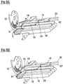
- the product holder 18 is released by a lateral swinging.
- the product holder 18 can be pivoted relative to a pivot axis P parallel to the feed direction. It is conceivable that alternately always a product holder 18 'remains in engagement with the product 10 and provides for the feed or the stabilization of the product 10, while the other product holder 18 is moved back.
- an end piece of the product 10 is still fixed even on the full width, when the second product holder 18 is already on the way back against the feed Z.
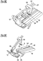
- FIGS. 8A to 8G an embodiment is shown in which the product holder 18, 18 'can be moved by means of independent linear units.
- the brackets 20, 20 ' are designed to be adjustable about a pivot axis S extending perpendicular to the feed direction Z.
- a delivery system is shown in a single-track application.
- the product holders 18, 18 ' are in each case assigned to a separate guide device 22, 22'. While the product 10 is being cut, the subsequent product 10 'may be loaded and gripped with the product holder 18'. The gripping takes place in particular in that the rear product holder 18 'pushes the product 10' against the front product holder 18.
- the position of the product beginning of the subsequent product 10 ' can be determined on the basis of the increase in power at the drive of the rear product holder 18', without the need for additional sensors.
- Fig. 8C It is shown that the end piece 34 is folded together with the holder 20 upwards. If the product 10 is cut open, the product holder 18 'moves first for a short distance counter to the feed direction Z and pivots 90 ° clockwise about the pivot axis S with the narrow end piece 34 upwards. The holder 20 is also made narrow and does not affect any neighboring tracks.
- the subsequent product 10 can be immediately advanced to the cutting blade 10 and cut there.
- the product support 16 can be lowered to a new loading in the horizontal.
- the end piece 34 can be moved forward in the feed direction Z in a discharge chute 36.
- a pivoting of the front, short product support 38 is not necessary here.
- the guide of the products 10, 10 ', 10" is provided by lateral separating webs 40, the driven product support 16 and a guaranteed driven roller from above.
- Fig. 8G shows the application of this concept to a multi-lane operation.
- a two-track operation for example, four linear drives can be provided. Since the product holders 18, 18 'are each assigned to a single track, the feeding device can be modularly expanded as desired by further tracks.
- a quasi-continuous loading can be achieved so that only short loading pauses result. Also, all products are always kept safe.
Landscapes
- Life Sciences & Earth Sciences (AREA)
- Forests & Forestry (AREA)
- Engineering & Computer Science (AREA)
- Mechanical Engineering (AREA)
- Attitude Control For Articles On Conveyors (AREA)
- Preparation Of Fruits And Vegetables (AREA)
- Specific Conveyance Elements (AREA)
Claims (15)
- Dispositif d'alimentation pour amener des produits alimentaires (10, 10', 10") jusqu'à une unité de coupe (14), comportant
au moins un moyen d'appui de produit (16) présentant au moins une trace et destiné à recevoir plusieurs produits (10, 10', 10") agencés les uns derrière les autres,
caractérisé en ce que
il est prévu au moins deux moyens de maintien de produit (18, 18', 18") par trace, l'un au moins des moyens de maintien de produit (18, 18', 18") comprenant une monture (20, 20', 20") pour maintenir une extrémité d'un produit (10) située en arrière, vue en direction d'alimentation (Z), et une butée (24, 24', 24") pour une extrémité avant d'un produit suivant (10'). - Dispositif d'alimentation selon la revendication 1,
caractérisé en ce que
au moins deux moyens de maintien de produit (18, 18', 18") comprennent chacun une monture (20, 20', 20") pour maintenir une extrémité d'un produit (1, 10', 10") située en arrière, vue en direction d'alimentation (Z). - Dispositif d'alimentation selon la revendication 1 ou 2,
caractérisé en ce que
au moins deux moyens de maintien de produit (18, 18', 18") comprennent chacun une butée (24, 24', 24") pour une extrémité avant d'un produit suivant (10'). - Dispositif d'alimentation selon l'une des revendications précédentes,
caractérisé en ce que
le moyen de maintien de produit (18, 18', 18") est réalisé pour fixer et/ou définir la position du produit suivant (10'). - Dispositif d'alimentation selon l'une des revendications précédentes,
caractérisé en ce que
une butée (24, 24', 24") du moyen de maintien de produit (18, 18', 18") comprend une surface de butée qui est au moins sensiblement plane et/ou qui est adaptée à la forme de l'extrémité avant du produit suivant (10'), et/ou en ce que le moyen de maintien de produit (18, 18', 18') comprend une autre monture (26) pour maintenir une extrémité avant d'un produit suivant (10'). - Dispositif d'alimentation selon l'une des revendications précédentes,
caractérisé en ce que
le moyen de maintien de produit (18, 18', 18") et/ou une butée (24, 24', 24") du moyen de maintien de produit (18, 18', 18") est réalisé(e) variable en longueur en direction d'alimentation (Z). - Dispositif d'alimentation selon l'une des revendications précédentes,
caractérisé en ce que
il est prévu un moyen de guidage (22, 22') pour le moyen de maintien de produit (18, 18', 18"), à l'aide duquel le moyen de maintien de produit (18, 18', 18") peut être guidé parallèlement à la direction d'alimentation (Z). - Dispositif d'alimentation selon l'une des revendications précédentes,
caractérisé en ce que
le moyen de maintien de produit (18, 18', 18") et/ou le moyen de guidage (22, 22') comprend un dispositif de déplacement qui est réalisé pour déplacer le moyen de maintien de produit (18, 18', 18") hors d'une zone d'alimentation. - Dispositif d'alimentation selon l'une des revendications précédentes,
caractérisé en ce que
le moyen de maintien de produit (18, 18', 18") et/ou la monture (20, 20', 20") est relié(e) ou susceptible d'être relié(e) de façon détachable au moyen de guidage (22, 22'), et/ou en ce qu'un moyen de guidage séparé (22, 22') et/ou un entraînement séparé est associé à chaque moyen de maintien de produit (18, 18', 18"). - Dispositif d'alimentation selon l'une des revendications précédentes,
caractérisé en ce que
les montures (20, 20', 20") de deux éléments de maintien de produit (18, 18', 18") sont réalisées pour maintenir au moins temporairement l'extrémité arrière, vue en direction d'alimentation (Z), du même produit (10, 10', 10"). - Dispositif d'alimentation selon l'une des revendications précédentes,
caractérisé en ce que
l'un au moins des moyens de maintien de produit (18, 18', 18") est relié à un ensemble formant tracteur (32) et/ou est intégré dans un ensemble formant tracteur (32), et/ou en ce que la monture (20, 20', 20") peut être pivotée et/ou déplacée par rapport à un axe (P, S) parallèle ou perpendiculaire à la direction d'alimentation (Z). - Dispositif de coupe de produits alimentaires, en particulier trancheuse à haute performance, comportant une unité de coupe (14) qui comprend au moins un couteau (12) mobile en rotation et/ou en révolution pendant l'opération de coupe, et comportant un dispositif d'alimentation selon l'une des revendications précédentes.
- Procédé d'alimentation pour amener des produits alimentaires (10, 10', 10") jusqu'à une unité de coupe (14) au moyen d'un dispositif d'alimentation selon l'une des revendications 1 à 11, dans lequel
plusieurs produits (10, 10', 10") agencés les uns derrière les autres sont reçus sur le moyen d'appui de produit (16) présentant au moins une trace, la monture (20, 20', 20") dudit un moyen de maintien de produit (18, 18', 18") maintient une extrémité d'un produit (10), située en arrière, vue en direction d'alimentation (Z), pendant la coupe du produit (10), et
une extrémité avant d'un produit suivant (10') est poussée par l'autre moyen de maintien de produit suivant (18, 18', 18") contre la butée (24, 24', 24") du moyen d'appui de produit précédent (18, 18', 18"). - Procédé d'alimentation en produits alimentaires (10, 10', 10") selon la revendication 13,
dans lequel il est prévu au moins deux moyens de maintien de produit (18, 18', 18") par trace, qui maintiennent chacun par leurs montures (20, 20', 20") une extrémité d'un produit (10, 10', 10") située en arrière, vue en direction d'alimentation (Z). - Procédé selon la revendication 13 ou 14,
caractérisé en ce que
la monture (20, 20', 20") maintient l'extrémité arrière du produit (10, 10', 10") jusqu'à ce que le produit (10) soit coupé, exception faite d'un morceau final (34),
la monture (20, 20', 20") est pivotée et/ou déplacée par rapport à un axe (S) perpendiculaire à la direction d'alimentation (Z),
la monture (20, 20', 20") remet le morceau final (34),
ou en ce que la monture (20, 20', 20") remet tout d'abord le morceau final (34) et est ensuite pivotée et/ou déplacée par rapport à un axe (S) perpendiculaire à la direction d'alimentation (Z),
en ce que le moyen de maintien de produit (18, 18', 18") et/ou la monture (20, 20', 20") est déplacé(e) parallèlement et en sens opposé à la direction d'alimentation (Z), et
en ce que la monture (20, 20', 20") maintient une extrémité arrière d'un produit suivant (10').
Applications Claiming Priority (1)
| Application Number | Priority Date | Filing Date | Title |
|---|---|---|---|
| DE102015107716.7A DE102015107716A1 (de) | 2015-05-18 | 2015-05-18 | Zuführvorrichtung |
Publications (2)
| Publication Number | Publication Date |
|---|---|
| EP3095566A1 EP3095566A1 (fr) | 2016-11-23 |
| EP3095566B1 true EP3095566B1 (fr) | 2017-12-27 |
Family
ID=56008493
Family Applications (1)
| Application Number | Title | Priority Date | Filing Date |
|---|---|---|---|
| EP16169372.6A Active EP3095566B1 (fr) | 2015-05-18 | 2016-05-12 | Dispositif d'allimentation d'une découpeuse |
Country Status (3)
| Country | Link |
|---|---|
| US (1) | US10751899B2 (fr) |
| EP (1) | EP3095566B1 (fr) |
| DE (1) | DE102015107716A1 (fr) |
Families Citing this family (7)
| Publication number | Priority date | Publication date | Assignee | Title |
|---|---|---|---|---|
| DE102015118202A1 (de) * | 2015-10-26 | 2017-04-27 | Textor Maschinenbau GmbH | Vorrichtung und verfahren zum aufschneiden von lebensmittelprodukten |
| ES2958751T3 (es) * | 2017-05-02 | 2024-02-14 | Gea Food Solutions Germany Gmbh | Sistema de agarre para la sujeción de barras de alimentos a cortar, dispositivo de corte, procedimiento |
| US11059197B2 (en) | 2017-08-24 | 2021-07-13 | Cozzini Llc | Method of slicing a food item and slicing mechanism employing a gripping element that generates a vacuum grip |
| DE102017126377A1 (de) * | 2017-11-10 | 2019-05-16 | Weber Maschinenbau Gmbh Breidenbach | Greifer |
| US11498138B2 (en) * | 2019-01-23 | 2022-11-15 | Steve Dunivan | Bandsaw automated portioning saw system and method of use |
| US11639008B2 (en) * | 2019-12-17 | 2023-05-02 | High Liner Foods Incorporated | Method and apparatus for cutting food into unique geometric portions |
| DE102021101315A1 (de) | 2021-01-22 | 2022-07-28 | Multivac Sepp Haggenmüller Se & Co. Kg | Mehrspurige Aufschneide-Maschine mit unabhängig ansteuerbaren Greifern |
Family Cites Families (18)
| Publication number | Priority date | Publication date | Assignee | Title |
|---|---|---|---|---|
| GB505821A (en) * | 1937-12-16 | 1939-05-17 | Micro Westco Inc | Improvements in or relating to feed mechanism for slicing machines |
| US2801662A (en) * | 1955-08-18 | 1957-08-06 | Arrigo Bros Co Of California D | Apparatus for trimming vegetables and the like |
| US4321847A (en) * | 1979-11-09 | 1982-03-30 | Cashin Systems Corp. | Continuous cold cut slicing machine |
| DE3302946C2 (de) | 1982-02-05 | 1986-12-04 | H. Wohlenberg KG GmbH & Co, 3000 Hannover | Drei-Messer-Schneidemaschine |
| DE3239178A1 (de) * | 1982-10-22 | 1984-04-26 | Natec Reich, Summer GmbH & Co KG, 8999 Heimenkirch | Maschine zum schneiden von schneidgutriegeln |
| FR2726779B1 (fr) * | 1994-11-15 | 1996-12-20 | Mecamatic | Installation pour le tranchage de pates en croute et autres aliments presentes en pain |
| DE19801782A1 (de) | 1998-01-19 | 1999-07-22 | Alpma Alpenland Masch | Verfahren und Vorrichtung zum Transport eines Gegenstands |
| US7832316B2 (en) * | 2000-11-03 | 2010-11-16 | Weber Maschinenbau Gmbh & Co. Kg | Apparatus for the slicing of food products having two cutter heads |
| CN101083419B (zh) | 2001-10-01 | 2013-03-27 | 麦克纳莫绅有限公司 | 同步机器设计及制造 |
| GB2386317B (en) * | 2002-03-13 | 2004-02-04 | Aew Eng Co Ltd | Improvements in and relating to slicing machines |
| DE20218439U1 (de) * | 2002-11-27 | 2003-01-30 | Siller Rudi | Maschine zum Schneiden von stabförmigen Lebensmitteln |
| JP4768643B2 (ja) * | 2007-01-17 | 2011-09-07 | アサヒ技研株式会社 | ハム原木等のスライス装置 |
| JP2012516130A (ja) | 2009-01-23 | 2012-07-12 | マグネモーション インコーポレイテッド | 短ブロックのリニア同期モータおよび切り替え機構によって動力供給される改良された輸送システム |
| US20100257984A1 (en) * | 2009-04-09 | 2010-10-14 | Scaroni David W | Produce processing apparatus |
| ES2444651T3 (es) * | 2009-07-07 | 2014-02-26 | Areva Gmbh | Instalación de aislamiento y procedimiento asociado de aislamiento |
| IT1397062B1 (it) * | 2009-12-29 | 2012-12-28 | Perini Fabio Spa | Macchina troncatrice per il taglio di rotoli di materiale nastriforme |
| ES2535968T3 (es) * | 2010-08-18 | 2015-05-19 | Weber Maschinenbau Gmbh Breidenbach | Procedimiento y dispositivo para el loncheado de productos alimenticios |
| DE102012214741A1 (de) * | 2012-08-20 | 2014-02-20 | Textor Maschinenbau GmbH | Vorrichtung und Verfahren zum Aufschneiden von Lebensmittelprodukten |
-
2015
- 2015-05-18 DE DE102015107716.7A patent/DE102015107716A1/de not_active Withdrawn
-
2016
- 2016-05-12 EP EP16169372.6A patent/EP3095566B1/fr active Active
- 2016-05-17 US US15/157,309 patent/US10751899B2/en active Active
Non-Patent Citations (1)
| Title |
|---|
| None * |
Also Published As
| Publication number | Publication date |
|---|---|
| US20160339597A1 (en) | 2016-11-24 |
| EP3095566A1 (fr) | 2016-11-23 |
| US10751899B2 (en) | 2020-08-25 |
| DE102015107716A1 (de) | 2016-11-24 |
Similar Documents
| Publication | Publication Date | Title |
|---|---|---|
| EP3095566B1 (fr) | Dispositif d'allimentation d'une découpeuse | |
| EP2420362B1 (fr) | Procédé et dispositif destinés à la coupe de produits alimentaires | |
| EP3288731B1 (fr) | Dispositif de découpe | |
| EP2848380B1 (fr) | Dispositif de découpe de produits alimentaires et procédé d'application de feuillets intermédiaires | |
| EP2420364B1 (fr) | Equipement destiné à compléter une portion lors de la coupe sur plusieurs voies | |
| EP2468466B1 (fr) | Dispositif et procédé destinés à la coupe de plusieurs produits alimentaires | |
| EP1832399B2 (fr) | Procédé et dispositif pour la coupe de produits imprimés | |
| EP3170632B1 (fr) | Dispositif et procédé destinés au découpage de produits alimentaires | |
| EP1680263B1 (fr) | Procede et appareil pour decouper des barres de produits alimentaires | |
| DE4425155A1 (de) | Anlage zur Herstellung von Wellpappebögen mit veränderbarem Format | |
| DE102012009648A1 (de) | Spreizeinrichtung | |
| EP3172020A1 (fr) | Dispositif de coupe | |
| EP1473125B1 (fr) | Machine pour déplacer des livres dans une machine pour le rognage des livres | |
| DE10329842A1 (de) | Trennblatt-Spendevorrichtung und Spendeverfahren für Trennblätter | |
| EP3112104B1 (fr) | Dispositif d'amenee pour machine de découpe d'aliments | |
| EP2564998B1 (fr) | Procédé destiné à la découpe sur plusieurs voies de produits alimentaires | |
| EP3785543A2 (fr) | Dispositif de coupe | |
| EP1683612B1 (fr) | Procédé et dispositif pour transporter des produits plats flexibles, et pour les découper au même temps | |
| EP2556931A1 (fr) | Procédé et dispositif destinés au traitement d'une bande de matériau | |
| EP3380419B1 (fr) | Procédé et dispositif de mise en portions de tranches d'un produit alimentaire avec modification de forme, notamment pliage, de la portion | |
| EP3268174B1 (fr) | Procédé et dispositif pour éviter des emballages vides | |
| DE102009039825A1 (de) | Schneidmaschine | |
| EP3377282A1 (fr) | Procédé de formation de portion de manière indépendante à partir de tranches de produits alimentaires dans plusieurs voies | |
| EP3386693B1 (fr) | Procédé permettant d'effectuer une coupe de parage | |
| DE102020102895A1 (de) | Vorrichtung und System zum Aufschneiden und Portionieren von Lebensmitteln |
Legal Events
| Date | Code | Title | Description |
|---|---|---|---|
| PUAI | Public reference made under article 153(3) epc to a published international application that has entered the european phase |
Free format text: ORIGINAL CODE: 0009012 |
|
| AK | Designated contracting states |
Kind code of ref document: A1 Designated state(s): AL AT BE BG CH CY CZ DE DK EE ES FI FR GB GR HR HU IE IS IT LI LT LU LV MC MK MT NL NO PL PT RO RS SE SI SK SM TR |
|
| AX | Request for extension of the european patent |
Extension state: BA ME |
|
| 17P | Request for examination filed |
Effective date: 20170406 |
|
| RBV | Designated contracting states (corrected) |
Designated state(s): AL AT BE BG CH CY CZ DE DK EE ES FI FR GB GR HR HU IE IS IT LI LT LU LV MC MK MT NL NO PL PT RO RS SE SI SK SM TR |
|
| 17Q | First examination report despatched |
Effective date: 20170712 |
|
| GRAP | Despatch of communication of intention to grant a patent |
Free format text: ORIGINAL CODE: EPIDOSNIGR1 |
|
| RIC1 | Information provided on ipc code assigned before grant |
Ipc: B65G 47/28 20060101ALN20170831BHEP Ipc: B26D 7/06 20060101AFI20170831BHEP |
|
| RIC1 | Information provided on ipc code assigned before grant |
Ipc: B26D 7/06 20060101AFI20170906BHEP Ipc: B65G 47/28 20060101ALN20170906BHEP |
|
| INTG | Intention to grant announced |
Effective date: 20170922 |
|
| GRAS | Grant fee paid |
Free format text: ORIGINAL CODE: EPIDOSNIGR3 |
|
| GRAA | (expected) grant |
Free format text: ORIGINAL CODE: 0009210 |
|
| AK | Designated contracting states |
Kind code of ref document: B1 Designated state(s): AL AT BE BG CH CY CZ DE DK EE ES FI FR GB GR HR HU IE IS IT LI LT LU LV MC MK MT NL NO PL PT RO RS SE SI SK SM TR |
|
| REG | Reference to a national code |
Ref country code: GB Ref legal event code: FG4D Free format text: NOT ENGLISH |
|
| REG | Reference to a national code |
Ref country code: CH Ref legal event code: EP |
|
| REG | Reference to a national code |
Ref country code: AT Ref legal event code: REF Ref document number: 957901 Country of ref document: AT Kind code of ref document: T Effective date: 20180115 |
|
| REG | Reference to a national code |
Ref country code: IE Ref legal event code: FG4D Free format text: LANGUAGE OF EP DOCUMENT: GERMAN |
|
| REG | Reference to a national code |
Ref country code: DE Ref legal event code: R096 Ref document number: 502016000400 Country of ref document: DE |
|
| PG25 | Lapsed in a contracting state [announced via postgrant information from national office to epo] |
Ref country code: FI Free format text: LAPSE BECAUSE OF FAILURE TO SUBMIT A TRANSLATION OF THE DESCRIPTION OR TO PAY THE FEE WITHIN THE PRESCRIBED TIME-LIMIT Effective date: 20171227 Ref country code: NO Free format text: LAPSE BECAUSE OF FAILURE TO SUBMIT A TRANSLATION OF THE DESCRIPTION OR TO PAY THE FEE WITHIN THE PRESCRIBED TIME-LIMIT Effective date: 20180327 Ref country code: LT Free format text: LAPSE BECAUSE OF FAILURE TO SUBMIT A TRANSLATION OF THE DESCRIPTION OR TO PAY THE FEE WITHIN THE PRESCRIBED TIME-LIMIT Effective date: 20171227 |
|
| REG | Reference to a national code |
Ref country code: NL Ref legal event code: MP Effective date: 20171227 |
|
| REG | Reference to a national code |
Ref country code: LT Ref legal event code: MG4D |
|
| PG25 | Lapsed in a contracting state [announced via postgrant information from national office to epo] |
Ref country code: BG Free format text: LAPSE BECAUSE OF FAILURE TO SUBMIT A TRANSLATION OF THE DESCRIPTION OR TO PAY THE FEE WITHIN THE PRESCRIBED TIME-LIMIT Effective date: 20180327 Ref country code: RS Free format text: LAPSE BECAUSE OF FAILURE TO SUBMIT A TRANSLATION OF THE DESCRIPTION OR TO PAY THE FEE WITHIN THE PRESCRIBED TIME-LIMIT Effective date: 20171227 Ref country code: LV Free format text: LAPSE BECAUSE OF FAILURE TO SUBMIT A TRANSLATION OF THE DESCRIPTION OR TO PAY THE FEE WITHIN THE PRESCRIBED TIME-LIMIT Effective date: 20171227 Ref country code: GR Free format text: LAPSE BECAUSE OF FAILURE TO SUBMIT A TRANSLATION OF THE DESCRIPTION OR TO PAY THE FEE WITHIN THE PRESCRIBED TIME-LIMIT Effective date: 20180328 Ref country code: HR Free format text: LAPSE BECAUSE OF FAILURE TO SUBMIT A TRANSLATION OF THE DESCRIPTION OR TO PAY THE FEE WITHIN THE PRESCRIBED TIME-LIMIT Effective date: 20171227 |
|
| PG25 | Lapsed in a contracting state [announced via postgrant information from national office to epo] |
Ref country code: NL Free format text: LAPSE BECAUSE OF FAILURE TO SUBMIT A TRANSLATION OF THE DESCRIPTION OR TO PAY THE FEE WITHIN THE PRESCRIBED TIME-LIMIT Effective date: 20171227 |
|
| PG25 | Lapsed in a contracting state [announced via postgrant information from national office to epo] |
Ref country code: ES Free format text: LAPSE BECAUSE OF FAILURE TO SUBMIT A TRANSLATION OF THE DESCRIPTION OR TO PAY THE FEE WITHIN THE PRESCRIBED TIME-LIMIT Effective date: 20171227 Ref country code: CZ Free format text: LAPSE BECAUSE OF FAILURE TO SUBMIT A TRANSLATION OF THE DESCRIPTION OR TO PAY THE FEE WITHIN THE PRESCRIBED TIME-LIMIT Effective date: 20171227 Ref country code: EE Free format text: LAPSE BECAUSE OF FAILURE TO SUBMIT A TRANSLATION OF THE DESCRIPTION OR TO PAY THE FEE WITHIN THE PRESCRIBED TIME-LIMIT Effective date: 20171227 Ref country code: CY Free format text: LAPSE BECAUSE OF FAILURE TO SUBMIT A TRANSLATION OF THE DESCRIPTION OR TO PAY THE FEE WITHIN THE PRESCRIBED TIME-LIMIT Effective date: 20171227 Ref country code: SK Free format text: LAPSE BECAUSE OF FAILURE TO SUBMIT A TRANSLATION OF THE DESCRIPTION OR TO PAY THE FEE WITHIN THE PRESCRIBED TIME-LIMIT Effective date: 20171227 |
|
| PG25 | Lapsed in a contracting state [announced via postgrant information from national office to epo] |
Ref country code: RO Free format text: LAPSE BECAUSE OF FAILURE TO SUBMIT A TRANSLATION OF THE DESCRIPTION OR TO PAY THE FEE WITHIN THE PRESCRIBED TIME-LIMIT Effective date: 20171227 Ref country code: IS Free format text: LAPSE BECAUSE OF FAILURE TO SUBMIT A TRANSLATION OF THE DESCRIPTION OR TO PAY THE FEE WITHIN THE PRESCRIBED TIME-LIMIT Effective date: 20180427 Ref country code: SM Free format text: LAPSE BECAUSE OF FAILURE TO SUBMIT A TRANSLATION OF THE DESCRIPTION OR TO PAY THE FEE WITHIN THE PRESCRIBED TIME-LIMIT Effective date: 20171227 Ref country code: PL Free format text: LAPSE BECAUSE OF FAILURE TO SUBMIT A TRANSLATION OF THE DESCRIPTION OR TO PAY THE FEE WITHIN THE PRESCRIBED TIME-LIMIT Effective date: 20171227 Ref country code: IT Free format text: LAPSE BECAUSE OF FAILURE TO SUBMIT A TRANSLATION OF THE DESCRIPTION OR TO PAY THE FEE WITHIN THE PRESCRIBED TIME-LIMIT Effective date: 20171227 |
|
| PG25 | Lapsed in a contracting state [announced via postgrant information from national office to epo] |
Ref country code: MT Free format text: LAPSE BECAUSE OF FAILURE TO SUBMIT A TRANSLATION OF THE DESCRIPTION OR TO PAY THE FEE WITHIN THE PRESCRIBED TIME-LIMIT Effective date: 20171227 |
|
| REG | Reference to a national code |
Ref country code: DE Ref legal event code: R097 Ref document number: 502016000400 Country of ref document: DE |
|
| PLBE | No opposition filed within time limit |
Free format text: ORIGINAL CODE: 0009261 |
|
| STAA | Information on the status of an ep patent application or granted ep patent |
Free format text: STATUS: NO OPPOSITION FILED WITHIN TIME LIMIT |
|
| PG25 | Lapsed in a contracting state [announced via postgrant information from national office to epo] |
Ref country code: DK Free format text: LAPSE BECAUSE OF FAILURE TO SUBMIT A TRANSLATION OF THE DESCRIPTION OR TO PAY THE FEE WITHIN THE PRESCRIBED TIME-LIMIT Effective date: 20171227 |
|
| 26N | No opposition filed |
Effective date: 20180928 |
|
| REG | Reference to a national code |
Ref country code: BE Ref legal event code: MM Effective date: 20180531 |
|
| PG25 | Lapsed in a contracting state [announced via postgrant information from national office to epo] |
Ref country code: MC Free format text: LAPSE BECAUSE OF FAILURE TO SUBMIT A TRANSLATION OF THE DESCRIPTION OR TO PAY THE FEE WITHIN THE PRESCRIBED TIME-LIMIT Effective date: 20171227 |
|
| REG | Reference to a national code |
Ref country code: IE Ref legal event code: MM4A |
|
| PG25 | Lapsed in a contracting state [announced via postgrant information from national office to epo] |
Ref country code: SI Free format text: LAPSE BECAUSE OF FAILURE TO SUBMIT A TRANSLATION OF THE DESCRIPTION OR TO PAY THE FEE WITHIN THE PRESCRIBED TIME-LIMIT Effective date: 20171227 |
|
| PG25 | Lapsed in a contracting state [announced via postgrant information from national office to epo] |
Ref country code: LU Free format text: LAPSE BECAUSE OF NON-PAYMENT OF DUE FEES Effective date: 20180512 |
|
| PG25 | Lapsed in a contracting state [announced via postgrant information from national office to epo] |
Ref country code: FR Free format text: LAPSE BECAUSE OF NON-PAYMENT OF DUE FEES Effective date: 20180531 Ref country code: IE Free format text: LAPSE BECAUSE OF NON-PAYMENT OF DUE FEES Effective date: 20180512 |
|
| PG25 | Lapsed in a contracting state [announced via postgrant information from national office to epo] |
Ref country code: BE Free format text: LAPSE BECAUSE OF NON-PAYMENT OF DUE FEES Effective date: 20180531 |
|
| REG | Reference to a national code |
Ref country code: CH Ref legal event code: PL |
|
| PG25 | Lapsed in a contracting state [announced via postgrant information from national office to epo] |
Ref country code: CH Free format text: LAPSE BECAUSE OF NON-PAYMENT OF DUE FEES Effective date: 20190531 Ref country code: LI Free format text: LAPSE BECAUSE OF NON-PAYMENT OF DUE FEES Effective date: 20190531 |
|
| PG25 | Lapsed in a contracting state [announced via postgrant information from national office to epo] |
Ref country code: TR Free format text: LAPSE BECAUSE OF FAILURE TO SUBMIT A TRANSLATION OF THE DESCRIPTION OR TO PAY THE FEE WITHIN THE PRESCRIBED TIME-LIMIT Effective date: 20171227 |
|
| PG25 | Lapsed in a contracting state [announced via postgrant information from national office to epo] |
Ref country code: PT Free format text: LAPSE BECAUSE OF FAILURE TO SUBMIT A TRANSLATION OF THE DESCRIPTION OR TO PAY THE FEE WITHIN THE PRESCRIBED TIME-LIMIT Effective date: 20171227 |
|
| PG25 | Lapsed in a contracting state [announced via postgrant information from national office to epo] |
Ref country code: MK Free format text: LAPSE BECAUSE OF NON-PAYMENT OF DUE FEES Effective date: 20171227 Ref country code: SE Free format text: LAPSE BECAUSE OF FAILURE TO SUBMIT A TRANSLATION OF THE DESCRIPTION OR TO PAY THE FEE WITHIN THE PRESCRIBED TIME-LIMIT Effective date: 20171227 Ref country code: HU Free format text: LAPSE BECAUSE OF FAILURE TO SUBMIT A TRANSLATION OF THE DESCRIPTION OR TO PAY THE FEE WITHIN THE PRESCRIBED TIME-LIMIT; INVALID AB INITIO Effective date: 20160512 |
|
| PG25 | Lapsed in a contracting state [announced via postgrant information from national office to epo] |
Ref country code: AL Free format text: LAPSE BECAUSE OF FAILURE TO SUBMIT A TRANSLATION OF THE DESCRIPTION OR TO PAY THE FEE WITHIN THE PRESCRIBED TIME-LIMIT Effective date: 20171227 |
|
| REG | Reference to a national code |
Ref country code: AT Ref legal event code: MM01 Ref document number: 957901 Country of ref document: AT Kind code of ref document: T Effective date: 20210512 |
|
| PG25 | Lapsed in a contracting state [announced via postgrant information from national office to epo] |
Ref country code: AT Free format text: LAPSE BECAUSE OF NON-PAYMENT OF DUE FEES Effective date: 20210512 |
|
| P01 | Opt-out of the competence of the unified patent court (upc) registered |
Effective date: 20230522 |
|
| PGFP | Annual fee paid to national office [announced via postgrant information from national office to epo] |
Ref country code: DE Payment date: 20230519 Year of fee payment: 8 |
|
| PGFP | Annual fee paid to national office [announced via postgrant information from national office to epo] |
Ref country code: GB Payment date: 20230522 Year of fee payment: 8 |
|
| REG | Reference to a national code |
Ref country code: DE Ref legal event code: R081 Ref document number: 502016000400 Country of ref document: DE Owner name: WEBER FOOD TECHNOLOGY GMBH, DE Free format text: FORMER OWNER: WEBER MASCHINENBAU GMBH BREIDENBACH, 35236 BREIDENBACH, DE |