EP3093464A1 - Kraftfahrzeug-wärmeübertragersystem - Google Patents
Kraftfahrzeug-wärmeübertragersystem Download PDFInfo
- Publication number
- EP3093464A1 EP3093464A1 EP16168970.8A EP16168970A EP3093464A1 EP 3093464 A1 EP3093464 A1 EP 3093464A1 EP 16168970 A EP16168970 A EP 16168970A EP 3093464 A1 EP3093464 A1 EP 3093464A1
- Authority
- EP
- European Patent Office
- Prior art keywords
- evaporator
- motor vehicle
- heat exchanger
- working medium
- heat
- Prior art date
- Legal status (The legal status is an assumption and is not a legal conclusion. Google has not performed a legal analysis and makes no representation as to the accuracy of the status listed.)
- Withdrawn
Links
Images

Classifications
-
- F—MECHANICAL ENGINEERING; LIGHTING; HEATING; WEAPONS; BLASTING
- F28—HEAT EXCHANGE IN GENERAL
- F28D—HEAT-EXCHANGE APPARATUS, NOT PROVIDED FOR IN ANOTHER SUBCLASS, IN WHICH THE HEAT-EXCHANGE MEDIA DO NOT COME INTO DIRECT CONTACT
- F28D7/00—Heat-exchange apparatus having stationary tubular conduit assemblies for both heat-exchange media, the media being in contact with different sides of a conduit wall
-
- B—PERFORMING OPERATIONS; TRANSPORTING
- B60—VEHICLES IN GENERAL
- B60H—ARRANGEMENTS OF HEATING, COOLING, VENTILATING OR OTHER AIR-TREATING DEVICES SPECIALLY ADAPTED FOR PASSENGER OR GOODS SPACES OF VEHICLES
- B60H1/00—Heating, cooling or ventilating devices
- B60H1/02—Heating, cooling or ventilating devices the heat being derived from the propulsion plant
- B60H1/14—Heating, cooling or ventilating devices the heat being derived from the propulsion plant other than from cooling liquid of the plant
- B60H1/18—Heating, cooling or ventilating devices the heat being derived from the propulsion plant other than from cooling liquid of the plant the air being heated from the plant exhaust gases
- B60H1/20—Heating, cooling or ventilating devices the heat being derived from the propulsion plant other than from cooling liquid of the plant the air being heated from the plant exhaust gases using an intermediate heat-transferring medium
-
- F—MECHANICAL ENGINEERING; LIGHTING; HEATING; WEAPONS; BLASTING
- F01—MACHINES OR ENGINES IN GENERAL; ENGINE PLANTS IN GENERAL; STEAM ENGINES
- F01N—GAS-FLOW SILENCERS OR EXHAUST APPARATUS FOR MACHINES OR ENGINES IN GENERAL; GAS-FLOW SILENCERS OR EXHAUST APPARATUS FOR INTERNAL-COMBUSTION ENGINES
- F01N5/00—Exhaust or silencing apparatus combined or associated with devices profiting by exhaust energy
- F01N5/02—Exhaust or silencing apparatus combined or associated with devices profiting by exhaust energy the devices using heat
-
- B—PERFORMING OPERATIONS; TRANSPORTING
- B60—VEHICLES IN GENERAL
- B60H—ARRANGEMENTS OF HEATING, COOLING, VENTILATING OR OTHER AIR-TREATING DEVICES SPECIALLY ADAPTED FOR PASSENGER OR GOODS SPACES OF VEHICLES
- B60H1/00—Heating, cooling or ventilating devices
- B60H1/00314—Arrangements permitting a rapid heating of the heating liquid
-
- F—MECHANICAL ENGINEERING; LIGHTING; HEATING; WEAPONS; BLASTING
- F02—COMBUSTION ENGINES; HOT-GAS OR COMBUSTION-PRODUCT ENGINE PLANTS
- F02G—HOT GAS OR COMBUSTION-PRODUCT POSITIVE-DISPLACEMENT ENGINE PLANTS; USE OF WASTE HEAT OF COMBUSTION ENGINES; NOT OTHERWISE PROVIDED FOR
- F02G5/00—Profiting from waste heat of combustion engines, not otherwise provided for
- F02G5/02—Profiting from waste heat of exhaust gases
- F02G5/04—Profiting from waste heat of exhaust gases in combination with other waste heat from combustion engines
-
- F—MECHANICAL ENGINEERING; LIGHTING; HEATING; WEAPONS; BLASTING
- F28—HEAT EXCHANGE IN GENERAL
- F28D—HEAT-EXCHANGE APPARATUS, NOT PROVIDED FOR IN ANOTHER SUBCLASS, IN WHICH THE HEAT-EXCHANGE MEDIA DO NOT COME INTO DIRECT CONTACT
- F28D15/00—Heat-exchange apparatus with the intermediate heat-transfer medium in closed tubes passing into or through the conduit walls ; Heat-exchange apparatus employing intermediate heat-transfer medium or bodies
- F28D15/02—Heat-exchange apparatus with the intermediate heat-transfer medium in closed tubes passing into or through the conduit walls ; Heat-exchange apparatus employing intermediate heat-transfer medium or bodies in which the medium condenses and evaporates, e.g. heat pipes
- F28D15/025—Heat-exchange apparatus with the intermediate heat-transfer medium in closed tubes passing into or through the conduit walls ; Heat-exchange apparatus employing intermediate heat-transfer medium or bodies in which the medium condenses and evaporates, e.g. heat pipes having non-capillary condensate return means
-
- F—MECHANICAL ENGINEERING; LIGHTING; HEATING; WEAPONS; BLASTING
- F28—HEAT EXCHANGE IN GENERAL
- F28D—HEAT-EXCHANGE APPARATUS, NOT PROVIDED FOR IN ANOTHER SUBCLASS, IN WHICH THE HEAT-EXCHANGE MEDIA DO NOT COME INTO DIRECT CONTACT
- F28D15/00—Heat-exchange apparatus with the intermediate heat-transfer medium in closed tubes passing into or through the conduit walls ; Heat-exchange apparatus employing intermediate heat-transfer medium or bodies
- F28D15/02—Heat-exchange apparatus with the intermediate heat-transfer medium in closed tubes passing into or through the conduit walls ; Heat-exchange apparatus employing intermediate heat-transfer medium or bodies in which the medium condenses and evaporates, e.g. heat pipes
- F28D15/0266—Heat-exchange apparatus with the intermediate heat-transfer medium in closed tubes passing into or through the conduit walls ; Heat-exchange apparatus employing intermediate heat-transfer medium or bodies in which the medium condenses and evaporates, e.g. heat pipes with separate evaporating and condensing chambers connected by at least one conduit; Loop-type heat pipes; with multiple or common evaporating or condensing chambers
-
- F—MECHANICAL ENGINEERING; LIGHTING; HEATING; WEAPONS; BLASTING
- F28—HEAT EXCHANGE IN GENERAL
- F28D—HEAT-EXCHANGE APPARATUS, NOT PROVIDED FOR IN ANOTHER SUBCLASS, IN WHICH THE HEAT-EXCHANGE MEDIA DO NOT COME INTO DIRECT CONTACT
- F28D15/00—Heat-exchange apparatus with the intermediate heat-transfer medium in closed tubes passing into or through the conduit walls ; Heat-exchange apparatus employing intermediate heat-transfer medium or bodies
- F28D15/02—Heat-exchange apparatus with the intermediate heat-transfer medium in closed tubes passing into or through the conduit walls ; Heat-exchange apparatus employing intermediate heat-transfer medium or bodies in which the medium condenses and evaporates, e.g. heat pipes
- F28D15/04—Heat-exchange apparatus with the intermediate heat-transfer medium in closed tubes passing into or through the conduit walls ; Heat-exchange apparatus employing intermediate heat-transfer medium or bodies in which the medium condenses and evaporates, e.g. heat pipes with tubes having a capillary structure
- F28D15/043—Heat-exchange apparatus with the intermediate heat-transfer medium in closed tubes passing into or through the conduit walls ; Heat-exchange apparatus employing intermediate heat-transfer medium or bodies in which the medium condenses and evaporates, e.g. heat pipes with tubes having a capillary structure forming loops, e.g. capillary pumped loops
-
- F—MECHANICAL ENGINEERING; LIGHTING; HEATING; WEAPONS; BLASTING
- F28—HEAT EXCHANGE IN GENERAL
- F28D—HEAT-EXCHANGE APPARATUS, NOT PROVIDED FOR IN ANOTHER SUBCLASS, IN WHICH THE HEAT-EXCHANGE MEDIA DO NOT COME INTO DIRECT CONTACT
- F28D15/00—Heat-exchange apparatus with the intermediate heat-transfer medium in closed tubes passing into or through the conduit walls ; Heat-exchange apparatus employing intermediate heat-transfer medium or bodies
- F28D15/02—Heat-exchange apparatus with the intermediate heat-transfer medium in closed tubes passing into or through the conduit walls ; Heat-exchange apparatus employing intermediate heat-transfer medium or bodies in which the medium condenses and evaporates, e.g. heat pipes
- F28D2015/0216—Heat-exchange apparatus with the intermediate heat-transfer medium in closed tubes passing into or through the conduit walls ; Heat-exchange apparatus employing intermediate heat-transfer medium or bodies in which the medium condenses and evaporates, e.g. heat pipes having particular orientation, e.g. slanted, or being orientation-independent
-
- F—MECHANICAL ENGINEERING; LIGHTING; HEATING; WEAPONS; BLASTING
- F28—HEAT EXCHANGE IN GENERAL
- F28D—HEAT-EXCHANGE APPARATUS, NOT PROVIDED FOR IN ANOTHER SUBCLASS, IN WHICH THE HEAT-EXCHANGE MEDIA DO NOT COME INTO DIRECT CONTACT
- F28D21/00—Heat-exchange apparatus not covered by any of the groups F28D1/00 - F28D20/00
- F28D2021/0019—Other heat exchangers for particular applications; Heat exchange systems not otherwise provided for
- F28D2021/008—Other heat exchangers for particular applications; Heat exchange systems not otherwise provided for for vehicles
-
- Y—GENERAL TAGGING OF NEW TECHNOLOGICAL DEVELOPMENTS; GENERAL TAGGING OF CROSS-SECTIONAL TECHNOLOGIES SPANNING OVER SEVERAL SECTIONS OF THE IPC; TECHNICAL SUBJECTS COVERED BY FORMER USPC CROSS-REFERENCE ART COLLECTIONS [XRACs] AND DIGESTS
- Y02—TECHNOLOGIES OR APPLICATIONS FOR MITIGATION OR ADAPTATION AGAINST CLIMATE CHANGE
- Y02T—CLIMATE CHANGE MITIGATION TECHNOLOGIES RELATED TO TRANSPORTATION
- Y02T10/00—Road transport of goods or passengers
- Y02T10/10—Internal combustion engine [ICE] based vehicles
- Y02T10/12—Improving ICE efficiencies
Definitions
- the invention relates to a motor vehicle heat exchanger system.
- Heat pipes including loop heat pipes work purely passive, self-regulating and without additional pump. The heat transfer takes place by exploiting the enthalpy of vaporization, whereby losses of sensible heat via a steam line are negligible. Consequently, a highly efficient heat transfer is possible with heat pipes.
- a disadvantage of heat pipes is the limited transport performance under vibration. By vibrations, caused for example by the engine vibrations or shocks as a result of driving, act on the heat pipes forces on the working fluid within the capillary structure, which hinder the flow of the working fluid or even lead to leakage of the working fluid from the capillary structure.
- the invention is based on the prior art, the object of demonstrating an efficient and inexpensive motor vehicle heat exchanger system, which allows heat transfer from the exhaust gas to a customer in the motor vehicle, in particular an interior heating of the motor vehicle, without additional pump.
- a motor vehicle heat exchanger system has a closed circuit for a working medium.
- an evaporator is integrated.
- the evaporator is in contact with a heat source of the motor vehicle.
- the heat source may in particular be the hot exhaust gas from the internal combustion engine of the motor vehicle.
- the evaporator is arranged in the exhaust gas flow of the internal combustion engine of the motor vehicle and passes heat-transmitting with the exhaust gas in contact.
- other heat sources of a motor vehicle can be used, for example, the waste heat from electronic components or the power electronics of an electric vehicle.
- the electric motor of a motor vehicle itself can form the heat source, wherein the waste heat of the electric motor is used to evaporate the working fluid in the motor vehicle heat exchanger system.
- the working medium is evaporated and flows from there to a arranged in the motor vehicle above the evaporator capacitor.
- a heat exchange with a consumer takes place, wherein the vaporous working medium is condensed and liquefied.
- the return of the liquid working medium to the evaporator is gravity driven.
- the condenser may in particular be an air-cooled condenser in the air conditioning module of the motor vehicle or the condenser of an interior heating of the motor vehicle.
- the capacitor may be part of a heating unit for drive components such as the manual transmission or the engine oil itself.
- a pump is not required, whereby the complexity and cost of the motor vehicle heat exchanger system are low.
- a working medium in particular ethanol is used.
- water or other working media are possible.
- the evaporator is associated with a vapor collection chamber, is collected in the steam flowing from the evaporator and fed to the condenser.
- the evaporator can flow in the same direction in the case of the exhaust gas and steam, or be carried out in countercurrent. In the countercurrent configuration, the substances flow against.
- the evaporator comprises at least one evaporator module with a housing.
- the housing is in contact with the exhaust gas flow.
- a heat exchanger structure is incorporated.
- the heat exchanger structure is a means for increasing the heat transfer area and / or increasing the rate of evaporation.
- these agents have a porous structure.
- a heat exchanger structure can consist of an insert made of a wire mesh or of a metal fleece.
- the material used for a heat exchanger structure is preferably a good heat-conducting material, in particular metal, for use.
- a further advantageous aspect provides that the evaporator is preceded by an expansion tank for the working medium.
- the expansion tank is integrated in the return line.
- the exhaust gas derived from the internal combustion engine of the motor vehicle comes into contact with the evaporator as the exhaust gas flow.
- the evaporator has a passage for the exhaust gas flow.
- a central passage for the exhaust gas flow in the evaporator is provided.
- plate-like configured evaporator modules are arranged relative to one another such that one or more passages for the exhaust gas flow are formed between them.
- the plate-shaped evaporator modules consist in a simple construction of a housing shell or -tub, which is closed by a lid.
- a heat exchanger structure is incorporated and distant from the walls via spacers.
- the exhaust stream is passed centrally through the evaporator.
- the evaporator modules interconnected to the evaporator thus form a passage, in particular a centric passage, for the exhaust gas.
- the passage or the passage means may be provided for enlarging the heat transfer surface, in particular ribs, webs or lamellae.
- the means for increasing the heat transfer surface are formed by soldered michillererfinnen.
- the exhaust gas flows between the heat exchanger fins along the bottom walls of the housing shells. This ensures a very good heat transfer.
- the motor vehicle heat exchanger system comprises a closed circuit for a working medium AM and has an evaporator 1 integrated into the exhaust gas flow of an internal combustion engine of a motor vehicle.
- the exhaust gas flow or the exhaust gas is in the FIG. 1 illustrated by the arrow AG.
- the evaporator 1 comprises two plate-like configured evaporator modules 2, 3 (see also FIG. 2 ).
- Each evaporator module 2, 3 has a housing 4 formed of a housing shell 5 and a cover 6.
- the housing shell 5 has a directly with the exhaust gas AG coming into contact bottom wall 7 with a peripheral edge 8.
- a heat exchanger structure 9 is arranged in the housing 4.
- the heat exchanger structure 9 is a means for increasing the heat transfer surface and increasing the evaporation rate.
- the heat exchanger structure 9 in particular has a porous structure and is made of metal.
- the means is a sintered plate body 10.
- the plate body 10 is oriented in the housing shell 5 and sealed by spacers 11 relative to the lid 6.
- the spacers 11 are formed by seals.
- steam channels 12 are provided on the steam side DS directed towards the bottom wall 7 of the plate body 10.
- the steam channels 12 are integrally formed integrally in the plate body 10.
- the upper evaporator module 2 and the lower evaporator module 3 are connected to the evaporator 1 and form between them a passage 14 for the exhaust gas flow AG.
- the exhaust gas enters via the exhaust inlet 15 of the evaporator 1 in this and is passed through the passage 14 to the exhaust gas outlet 16.
- heat is transferred from the exhaust gas to the evaporator 1 and the working medium AM.
- the heat flow is in the FIG. 2 illustrated by the arrows WS.
- the heating of the working medium AM in the evaporator 1 takes place above the evaporation temperature of the working medium AM, so that the working medium in the evaporator 1 evaporates.
- the evaporator 1 is operated in DC, ie exhaust AG and vaporous working medium AM flow in the same direction.
- the vaporous working medium AM flows via a vapor line 19 to a condenser 20 arranged in the motor vehicle above the vaporizer 1.
- the condenser 20 heat is generated discharged from the vaporous working medium AM to a consumer.
- the capacitor 20 is part of the interior heating of the motor vehicle and / or associated with a climate module.
- the vaporous working medium AM is liquefied in the condenser 20 and flows gravity-driven via a return line 21 back into the evaporator 1.
- the evaporator 1 is preceded by a surge tank 22 for the working medium AM, which is integrated into the return line 21.
- the liquid working medium AM in each case enters the evaporator modules 2, 3 of the evaporator 1 via an inlet 23.
- the motor vehicle heat exchanger system according to the invention comes without an additional pump in the circulation.
Landscapes
- Engineering & Computer Science (AREA)
- Mechanical Engineering (AREA)
- General Engineering & Computer Science (AREA)
- Physics & Mathematics (AREA)
- Thermal Sciences (AREA)
- Chemical & Material Sciences (AREA)
- Combustion & Propulsion (AREA)
- Life Sciences & Earth Sciences (AREA)
- Sustainable Development (AREA)
- Air-Conditioning For Vehicles (AREA)
Abstract
Die Erfindung betrifft ein Kraftfahrzeug-Wärmeübertragersystem mit einem geschlossenen Kreislauf für ein Arbeitsmedium AM. In einem Verdampfer 1 wird das Arbeitsmedium AM verdampft und strömt zu einem im Kraftfahrzeug oberhalb des Verdampfers 1 angeordneten Kondensator 20. Das im Kondensator 20 kondensierte verflüssigte Arbeitsmedium AM wird schwerkraftgetrieben über eine Rücklaufleitung 21 in den Verdampfer 1 zurückgeführt. Vorzugsweise umfasst der Verdampfer 1 mehrere zu einer Einheit zusammengeschaltete Verdampfermodule 2, 3, wobei jedes Verdampfermodul 2, 3 ein Gehäuse 4 aufweist, in dem eine Wärmetauscherstruktur 5 zur Vergrößerung der Wärmeübertragungsfläche und der Verdampfungsrate angeordnet sind.
Description
- Die Erfindung betrifft ein Kraftfahrzeug-Wärmeübertragersystem.
- In Folge der zunehmenden Effizienz von Verbrennungsmotoren wird das Kühlwasser bei geringen Umgebungstemperaturen, insbesondere in kalten Jahreszeiten, nur langsam erwärmt. Hieraus resultiert ein Wärmedefizit für die Innenraumerwärmung von Kraftfahrzeugen mittels bekannter Wasserheizungen. Aus diesem Grund werden vor allen bei Dieselfahrzeugen serienmäßig elektrische Zuheizer, sogenannte PTC-(Positive Temperature Coefficient) Heizer, in das Klimamodul verbaut. Ein solcher Zuheizer erwärmt die in den Innenraum einströmende Luft zusätzlich. Allerdings führt die für den Betrieb benötigte elektrische Energie zu einem nicht unwesentlichen Kraftstoffmehrverbrauch.
- Aus dem Stand der Technik sind verschiedene Ansätze bekannt, die darauf Abzielen, das Wärmedefizit zu verringern, insbesondere durch den Einsatz von Abgaswärmetauschern, mit denen das Kühlwasser durch Abgaswärme beschleunigt erwärmt werden soll.
- Die
US 4,087,047 bzw.DE 25 23 645 A1 ebenso wie dieDE 38 06 418 C2 offenbaren Vorschläge, bei denen das Kühlwasser mittels Wärmerohren, sogenannten Heatpipes, beschleunigt erwärmt werden soll. Hierbei werden konventionelle Wärmerohre verwendet, wobei der Verdampferbereich des Wärmerohrs in Kontakt mit dem Abgas und der Kondensatorteil in Kontakt mit dem Kühlkreislauf des Motors steht. Bekanntermaßen sind Wärmerohre an der Innenwand mit Kapillarstrukturen versehen, die das Arbeitsmedium vom Kondensatorteil zurück in die Verdampferzone transportieren. - Im Umfang der
DE 10 2008 007 726 A1 wird ein Wärmerohr vom Kreislauftyp, eine sogenannte Loop Heat Pipe, beschrieben. Dieses Wärmerohr soll Wärme aus dem Abgas zu einem luftgekühlten Kondensator leiten. Über den Kondensator wird die in die Fahrerkabine einströmende Luft erwärmt. - Wärmerohre einschließlich Loop Heat Pipes arbeiten rein passiv, selbstregulierend und ohne zusätzliche Pumpe. Der Wärmetransport erfolgt durch Ausnutzung der Verdampfungsenthalpie, wodurch Verluste sensibler Wärme über eine Dampfleitung kaum ins Gewicht fallen. Demzufolge ist mit Wärmerohren ein höchsteffizienter Wärmetransport möglich. Ein Nachteil von Wärmerohren ist die eingeschränkte Transportleistung unter Vibration. Durch Vibrationen, beispielsweise hervorgerufen durch die Motorschwingungen oder Erschütterungen in Folge des Fahrbetriebs, wirken bei den Wärmerohren Kräfte auf das Arbeitsmedium innerhalb der Kapillarstruktur, welche die Strömung des Arbeitsmediums behindern oder sogar zu einem Austreten des Arbeitsmediums aus der Kapillarstruktur führen können. Bei Wärmerohren des Kreislauftyps bzw. Loop Heat Pipes tritt dieses Problem zwar in den Hintergrund, allerdings sind der Aufbau und die Fertigung von Loop Heat Pipes-Verdampfern zur Abgaswärmenutzung vergleichsweise komplex. Dadurch, dass Abgas sowie flüssiges und dampfförmiges Arbeitsmedium voneinander getrennt werden müssen, sind entsprechende Dichtungskonzepte notwendig. Des Weiteren resultieren aus den Anforderungen der Kapillarstruktur hinsichtlich Porengröße und Porösität vergleichsweise teure Bauteile.
- Der Erfindung liegt ausgehend vom Stand der Technik die Aufgabe zugrunde, ein effizientes und kostengünstiges Kraftfahrzeug-Wärmeübertragersystem aufzuzeigen, welches einen Wärmetransport aus dem Abgas zu einem Abnehmer im Kraftfahrzeug, insbesondere einer Innenraumbeheizung des Kraftfahrzeuges, ohne zusätzliche Pumpe ermöglicht.
- Die Lösung dieser Aufgabe zeigt Anspruch 1 auf.
- Vorteilhafte Ausgestaltungen und Weiterbildungen der Erfindung sind Gegenstand der abhängigen Ansprüche.
- Ein erfindungsgemäßes Kraftfahrzeug-Wärmeübertragersystem weist einen geschlossenen Kreislauf für ein Arbeitsmedium auf. In den Kreislauf ist ein Verdampfer integriert. Der Verdampfer steht mit einer Wärmequelle des Kraftfahrzeugs in Kontakt. Bei der Wärmequelle kann es sich insbesondere um das heiße Abgas aus der Brennkraftmaschine des Kraftfahrzeuges handeln. Hierbei ist der Verdampfer im Abgasstrom der Brennkraftmaschine des Kraftfahrzeugs angeordnet und gelangt wärmeübertragend mit dem Abgas in Kontakt. Zur Verdampfung des Arbeitsmediums im Verdampfer können aber auch andere Wärmequellen eines Kraftfahrzeugs genutzt werden, beispielsweise die Abwärme aus Elektronikbauteilen bzw. der Leistungselektronik eines Elektrofahrzeugs. Auch der Elektromotor eines Kraftfahrzeugs selbst kann die Wärmequelle bilden, wobei die Abwärme des Elektromotors zur Verdampfung des Arbeitsmediums im Kraftfahrzeug-Wärmeübertragersystem genutzt wird.
- Im Verdampfer wird das Arbeitsmedium verdampft und strömt von dort aus zu einem im Kraftfahrzeug oberhalb des Verdampfers angeordneten Kondensator. Im Kondensator erfolgt ein Wärmeaustausch mit einem Verbraucher, wobei das dampfförmige Arbeitsmedium kondensiert und verflüssigt wird. Der Rücklauf des flüssigen Arbeitsmediums zum Verdampfer erfolgt schwerkraftgetrieben.
- Bei dem Kondensator kann es sich insbesondere um einen luftgekühlten Kondensator im Klimamodul des Kraftfahrzeugs oder um den Kondensator einer Innenraumbeheizung des Kraftfahrzeugs handeln. Weiterhin kann der Kondensator Bestandteil einer Erwärmungseinheit für Antriebskomponenten wie dem Schaltgetriebe oder des Motoröls selbst sein.
- Da das Arbeitsmedium im geschlossenen Kreislauf allein aufgrund im System bzw. im Kreislauf vorhandener Dichteunterschiede, also durch freie Konvektion transportiert wird, ist eine Pumpe nicht erforderlich, wodurch die Komplexität und die Kosten des Kraftfahrzeug-Wärmeübertragersystems gering sind. Als Arbeitsmedium kommt insbesondere Ethanol zur Anwendung. Selbstverständlich sind auch Wasser oder andere Arbeitsmedien möglich.
- Vorteilhafterweise ist dem Verdampfer eine Dampfsammelkammer zugeordnet, in der aus dem Verdampfer strömender Dampf gesammelt und dem Kondensator zugeleitet wird.
- Grundsätzlich kann der Verdampfer im Gleichstrom bei dem Abgas und Dampf in die gleiche Richtung strömen oder im Gegenstrom ausgeführt sein. Bei der Gegenstrom-Konfiguration strömen sich die Stoffe entgegen.
- Ein besonders vorteilhafter Aspekt der Erfindung sieht vor, dass der Verdampfer zumindest ein Verdampfermodul umfasst mit einem Gehäuse. Das Gehäuse steht mit dem Abgasstrom in Kontakt. Im Gehäuse ist eine Wärmetauscherstruktur eingegliedert. Bei der Wärmetauscherstruktur handelt es sich um Mittel zur Vergrößerung der Wärmeübertragungsfläche und/oder zur Erhöhung der Verdampfungsrate. Bevorzugt besitzen diese Mittel eine poröse Struktur. Insbesondere kann eine Wärmetauscherstruktur durch einen Einsatz aus einem Drahtgestrick oder aus einem Metallvlies bestehen. Als Werkstoff für eine Wärmetauscherstruktur kommt bevorzugt ein gut wärmeleitender Werkstoff, insbesondere Metall, zur Anwendung.
- Ein weiterhin vorteilhafter Aspekt sieht vor, dass dem Verdampfer ein Ausgleichsbehälter für das Arbeitsmedium vorgeschaltet ist. Insbesondere ist der Ausgleichsbehälter in die Rücklaufleitung integriert.
- Das aus der Brennkraftmaschine des Kraftfahrzeugs abgeleitete Abgas gelangt als Abgasstrom mit dem Verdampfer in Kontakt. Grundsätzlich kann es ausreichen, dass das Abgas einseitig am Verdampfer entlang strömt. Eine praktisch vorteilhafte Ausführungsform sieht vor, dass der Verdampfer über einen Durchgang für den Abgasstrom verfügt. Insbesondere ist ein zentraler Durchgang für den Abgasstrom im Verdampfer vorgesehen. In diesem Zusammenhang ist es weiterhin vorteilhaft, wenn mehrere Verdampfermodule zu einem Verdampfer zusammengeschaltet sind.
- Ein vorteilhafter Aspekt hierbei sieht vor, dass plattenartig konfigurierte Verdampfermodule so zueinander angeordnet sind, dass zwischen diesen ein oder mehrere Durchgänge für den Abgasstrom gebildet sind. Die plattenförmigen Verdampfermodule bestehen in einer einfachen Bauweise aus einer Gehäuseschale bzw. -wanne, die durch einen Deckel verschlossen ist. Im Innenraum des Verdampfermoduls ist eine Wärmetauscherstruktur eingegliedert und gegenüber den Wänden über Abstandshalter distanziert.
- Vorzugsweise wird der Abgasstrom zentral durch den Verdampfer geleitet. Die zum Verdampfer zusammengeschalteten Verdampfermodule bilden mithin einen Durchgang, insbesondere einen zentrischen Durchgang, für das Abgas aus. In dem Durchgang oder den Durchgängen können Mittel zur Vergrößerung der Wärmeübergangsfläche vorgesehen sein, insbesondere Rippen, Stege oder Lamellen. Eine vorteilhafte Ausführungsform sieht vor, dass die Mittel zur Vergrößerung der Wärmeübergangsfläche durch eingelötete Wärmetauscherfinnen gebildet sind. Das Abgas strömt zwischen den Wärmetauscherfinnen entlang der Bodenwände der Gehäuseschalen. Hierdurch ist ein sehr guter Wärmeübergang gewährleistet.
- Im Vergleich zu Systemen mit Wärmerohr, insbesondere Wärmerohr vom Kreislauftyp bzw. Loop Heat Pipe, besteht der Vorteil, dass weder eine Kapillarstruktur noch ein Dichtungskonzept zur Trennung von Dampf und Flüssigphase im Verdampfer notwendig ist. An Stelle einer Kapillarstruktur wird eine poröse Wärmetauscherstruktur, z. B. ein Drahtgestrick oder ein Metallvlies, zur Erhöhung der Verdampfungsrate eingesetzt. Das erfindungsgemäße Kraftfahrzeug-Wärmeübertragersystem ist weniger komplex und damit kostengünstiger in der Fertigung.
- Die Erfindung ist nachfolgend anhand eines in den Zeichnungen dargestellten Ausführungsbeispiels ergänzend beschrieben.
- Figur 1
- technisch schematisiert ein erfindungsgemäßes Kraftfahrzeug-Wärmeübertragersystem und
- Figur 2
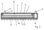
- wiederum technisch vereinfacht und schematisiert einen Längsschnitt durch ein Wärmetauschermodul des erfindungsgemäßen Kraftfahrzeug-Wärmeübertragersystems.
- Das Kraftfahrzeug-Wärmeübertragersystem umfasst einen geschlossenen Kreislauf für ein Arbeitsmedium AM und weist einen in den Abgasstrom einer Brennkraftmaschine eines Kraftfahrzeugs integrierten Verdampfer 1 auf. Der Abgasstrom bzw. das Abgas ist in der
Figur 1 durch den Pfeil AG verdeutlicht. - Der Verdampfer 1 umfasst zwei plattenartig konfigurierte Verdampfermodule 2, 3 (siehe hierzu auch
Figur 2 ). Jedes Verdampfermodul 2, 3 weist ein Gehäuse 4 gebildet aus einer Gehäuseschale 5 und einem Deckel 6 auf. Die Gehäuseschale 5 besitzt eine unmittelbar mit dem Abgas AG in Kontakt gelangende Bodenwand 7 mit einem umlaufenden Rand 8. Im Gehäuse 4 ist eine Wärmetauscherstruktur 9 angeordnet. Bei der Wärmetauscherstruktur 9 handelt es sich um Mittel zur Vergrößerung der Wärmeübertragerfläche und Erhöhung der Verdampfungsrate. Die Wärmetauscherstruktur 9 besitzt insbesondere eine poröse Struktur und besteht aus Metall. Insbesondere handelt es sich bei dem Mittel um einen gesinterten Plattenkörper 10. Der Plattenkörper 10 ist in der Gehäuseschale 5 lageorientiert und über Abstandshalter 11 gegenüber dem Deckel 6 abgedichtet. Die Abstandshalter 11 sind durch Dichtungen gebildet. Auf der zur Bodenwand 7 gerichteten Dampfseite DS des Plattenkörpers 10 sind Dampfkanäle 12 vorgesehen. Die Dampfkanäle 12 sind materialeinheitlich einstückig im Plattenkörper 10 ausgebildet. Auf der gegenüberliegenden Flüssigkeitsseite FS des Verdampfermoduls 2, 3 befindet sich ein Verteilraum 13 zur Verteilung des flüssigen Arbeitsmediums über die Flüssigkeitsseite FS des Plattenkörpers 10. - Das obere Verdampfermodul 2 und das untere Verdampfermodul 3 sind zum Verdampfer 1 zusammengeschlossen und bilden zwischen sich einen Durchgang 14 für den Abgasstrom AG aus. Das Abgas tritt über den Abgaseinlass 15 des Verdampfers 1 in diesen ein und wird durch den Durchgang 14 bis zum Abgasaustritt 16 geleitet. Hierbei wird Wärme vom Abgas auf den Verdampfer 1 und das Arbeitsmedium AM übertragen. Der Wärmestrom ist in der
Figur 2 durch die Pfeile WS verdeutlicht. Die Aufheizung des Arbeitsmediums AM im Verdampfer 1 erfolgt bis über die Verdampfungstemperatur des Arbeitsmediums AM, sodass das Arbeitsmedium im Verdampfer 1 verdampft. Der Verdampfer 1 wird im Gleichstrom betrieben, d. h. Abgas AG und dampfförmiges Arbeitsmedium AM strömen in die gleiche Richtung. Endseitig jedes Verdampfermoduls 2, 3 gelangt das dampfförmige Arbeitsmedium AM über einen Dampfaustritt 17 in eine Dampfsammelkammer 18. Von der Dampfsammelkammer 18 strömt das dampfförmige Arbeitsmedium AM über eine Dampfleitung 19 zu einem im Kraftfahrzeug oberhalb des Verdampfers 1 angeordneten Kondensator 20. Im Kondensator 20 wird Wärme vom dampfförmigen Arbeitsmedium AM an einen Verbraucher abgegeben. Insbesondere ist der Kondensator 20 Bestandteil der Innenraumbeheizung des Kraftfahrzeugs und/oder einem Klimamodul zugeordnet. In Folge der Wärmeabgabe wird das dampfförmige Arbeitsmedium AM im Kondensator 20 verflüssigt und strömt schwerkraftgetrieben über eine Rücklaufleitung 21 zurück in den Verdampfer 1. Dem Verdampfer 1 ist ein Ausgleichsbehälter 22 für das Arbeitsmedium AM vorgeschaltet, welcher in die Rücklaufleitung 21 integriert ist. Das flüssige Arbeitsmedium AM tritt jeweils über einen Einlass 23 wieder in die Verdampfermodule 2, 3 des Verdampfers 1 ein. - Das erfindungsgemäße Kraftfahrzeug-Wärmeübertragersystem kommt ohne eine zusätzliche Pumpe im Kreislauf aus.
-
- 1 - Verdampfer
- 2 - Verdampfermodul
- 3 - Verdampfermodul
- 4 - Gehäuse
- 5 - Gehäuseschale
- 6 - Deckel
- 7 - Bodenwand
- 8 - Rand v. 5
- 9 - Wärmetauscherstruktur
- 10- Plattenkörper
- 11 - Abstandshalter
- 12- Dampfkanal
- 13- Verteilraum
- 14- Durchgang
- 15- Abgaseinlass
- 16- Abgasaustritt
- 17 - Dampfaustritt
- 18- Dampfsammelkammer
- 19- Dampfleitung
- 20 - Kondensator
- 21 - Rücklaufleitung
- 22 - Ausgleichsbehälter
- 23 - Einlass
- AG - Abgasstrom
- AM - Arbeitsmedium
- DS - Dampfseite
- FS - Flüssigkeitsseite
Claims (6)
- Kraftfahrzeug-Wärmeübertragersystem, dadurch gekennzeichnet, dass ein geschlossener Kreislauf für ein Arbeitsmedium vorgesehen ist mit einem Verdampfer (1) in dem das Arbeitsmedium (AM) verdampft und zu einem im Kraftfahrzeug oberhalb des Verdampfers (1) angeordneten Kondensator (20) strömt und das im Kondensator (20) kondensierte flüssige Arbeitsmedium schwerkraftgetrieben über eine Rücklaufleitung (21) in den Verdampfer (1) zurückgeführt wird.
- Kraftfahrzeug-Wärmeübertragersystem nach Anspruch 1, dadurch gekennzeichnet, dass dem Verdampfer (1) eine Dampfsammelkammer (18) zugeordnet ist.
- Kraftfahrzeug-Wärmeübertragersystem nach Anspruch 1 oder 2, dadurch gekennzeichnet, dass der Verdampfer (1) zumindest ein Verdampfermodul (2, 3) umfasst mit einem Gehäuse (4) und einer im Gehäuse (4) angeordneten Wärmetauscherstruktur (9).
- Kraftfahrzeug-Wärmeübertragersystem nach Anspruch 3, dadurch gekennzeichnet, dass die Wärmetauscherstruktur (9) eine poröse Struktur besitzen.
- Kraftfahrzeug-Wärmeübertragersystem nach einem der Ansprüche 1 bis 4, dadurch gekennzeichnet, dass dem Verdampfer (1) ein Ausgleichsbehälter (22) für das Arbeitsmedium (AM) vorgeschaltet ist.
- Kraftfahrzeug-Wärmeübertragersystem nach einem der Ansprüche 1 bis 5, dadurch gekennzeichnet, dass der Verdampfer (1) über einen Durchgang (14) für den Abgasstrom (AG) verfügt.
Applications Claiming Priority (1)
| Application Number | Priority Date | Filing Date | Title |
|---|---|---|---|
| DE102015107427.3A DE102015107427A1 (de) | 2015-05-12 | 2015-05-12 | Kraftfahrzeug-Wärmeübertragersystem |
Publications (1)
| Publication Number | Publication Date |
|---|---|
| EP3093464A1 true EP3093464A1 (de) | 2016-11-16 |
Family
ID=56072217
Family Applications (1)
| Application Number | Title | Priority Date | Filing Date |
|---|---|---|---|
| EP16168970.8A Withdrawn EP3093464A1 (de) | 2015-05-12 | 2016-05-10 | Kraftfahrzeug-wärmeübertragersystem |
Country Status (5)
| Country | Link |
|---|---|
| US (1) | US20160332506A1 (de) |
| EP (1) | EP3093464A1 (de) |
| JP (1) | JP6247719B2 (de) |
| CN (1) | CN106152826B (de) |
| DE (1) | DE102015107427A1 (de) |
Families Citing this family (7)
| Publication number | Priority date | Publication date | Assignee | Title |
|---|---|---|---|---|
| US10746475B2 (en) * | 2016-08-01 | 2020-08-18 | California Institute Of Technology | Multi-phase thermal control apparatus, evaporators and methods of manufacture thereof |
| DE102017120164A1 (de) | 2017-09-01 | 2019-03-07 | Benteler Automobiltechnik Gmbh | Thermomanagementsystem für ein Elektrokraftfahrzeug |
| US12018892B2 (en) | 2020-11-02 | 2024-06-25 | California Institute Of Technology | Systems and methods for thermal management using separable heat pipes and methods of manufacture thereof |
| DE102022105719A1 (de) | 2022-03-11 | 2023-09-14 | Bayerische Motoren Werke Aktiengesellschaft | Kühlkreislauf für ein Kraftfahrzeug |
| US12359876B1 (en) * | 2023-03-01 | 2025-07-15 | Government Of The United States As Represented By The Secretary Of The Air Force | Ground testable spacecraft heat pipe |
| US12576693B2 (en) * | 2024-01-12 | 2026-03-17 | Toyota Motor Engineering & Manufacturing North America, Inc. | Cooling systems and assemblies, and vehicles including the same |
| DE102024124165A1 (de) | 2024-08-23 | 2026-02-26 | Deutsches Zentrum für Luft- und Raumfahrt e.V. | Wärmeübertragungssystem und Verfahren zum Betreiben eines Wärmeübertragungssystems |
Citations (8)
| Publication number | Priority date | Publication date | Assignee | Title |
|---|---|---|---|---|
| US3364951A (en) * | 1965-04-22 | 1968-01-23 | Olin Mathieson | Heat exchanger |
| DE1501589A1 (de) * | 1964-12-23 | 1970-01-15 | Olin Mathieson | Waermeaustauscher |
| DE2523645A1 (de) | 1975-05-28 | 1976-12-09 | Daimler Benz Ag | Heizung fuer kraftfahrzeuge |
| DE3902877A1 (de) * | 1989-02-01 | 1990-08-02 | Bayerische Motoren Werke Ag | Waermetauscher mit tauscherkoerpern aus sintermetall |
| DE3806418C2 (de) | 1987-03-09 | 1997-09-11 | Volvo Aero Aktiebolag | Auspuffgas-Wärmetauscher |
| DE102008007726A1 (de) | 2007-02-08 | 2008-09-04 | Denso Corp., Kariya | Abgaswärme-Rückgewinnungssystem |
| WO2009066177A2 (en) * | 2007-11-21 | 2009-05-28 | Toyota Jidosha Kabushiki Kaisha | Heat pipe, exhaust heat recoverer provided therewith |
| US20130233521A1 (en) * | 2010-11-01 | 2013-09-12 | Fujitsu Limited | Loop heat pipe and electronic equipment using the same |
Family Cites Families (24)
| Publication number | Priority date | Publication date | Assignee | Title |
|---|---|---|---|---|
| JPH0339285Y2 (de) * | 1986-03-31 | 1991-08-19 | ||
| JPH0276509U (de) * | 1988-11-30 | 1990-06-12 | ||
| DE69016119T2 (de) * | 1989-07-19 | 1995-08-31 | Showa Aluminum Corp | Wärmerohr. |
| BE1009410A3 (fr) * | 1995-06-14 | 1997-03-04 | B C A Sa | Dispositif de transport de chaleur. |
| US7080526B2 (en) * | 2004-01-07 | 2006-07-25 | Delphi Technologies, Inc. | Full plate, alternating layered refrigerant flow evaporator |
| JP4324925B2 (ja) * | 2004-09-28 | 2009-09-02 | 株式会社ティラド | 熱交換器 |
| US20060088746A1 (en) * | 2004-10-25 | 2006-04-27 | 3M Innovative Properties Company | Passive dual-phase cooling for fuel cell assemblies |
| CN100383963C (zh) * | 2005-07-08 | 2008-04-23 | 富准精密工业(深圳)有限公司 | 薄型环路式散热装置 |
| US8316927B2 (en) * | 2006-06-09 | 2012-11-27 | Denso Corporation | Loop heat pipe waste heat recovery device with pressure controlled mode valve |
| JP4259583B2 (ja) * | 2007-02-15 | 2009-04-30 | 株式会社デンソー | 排気熱回収装置 |
| DE102008027773A1 (de) * | 2007-06-28 | 2009-02-26 | Denso Corp., Kariya-shi | Abgaswärme-Rückgewinnungseinrichtung |
| JP4870702B2 (ja) * | 2008-03-13 | 2012-02-08 | トヨタ自動車株式会社 | 排気熱回収器 |
| JP2010275999A (ja) * | 2009-06-01 | 2010-12-09 | Toyota Motor Corp | 内燃機関の排気構造 |
| DE102009056274A1 (de) * | 2009-12-01 | 2011-06-09 | Benteler Automobiltechnik Gmbh | Wärmetauscher |
| DE102010002493A1 (de) * | 2010-03-02 | 2011-09-08 | Robert Bosch Gmbh | Thermoelektrischer Generator |
| DE102010031561A1 (de) * | 2010-07-20 | 2012-01-26 | Behr Gmbh & Co. Kg | System zur Nutzung von Abwärme eines Verbrennungsmotors |
| CN102723316A (zh) * | 2011-03-29 | 2012-10-10 | 北京奇宏科技研发中心有限公司 | 环路热管结构 |
| DE102011103110B4 (de) * | 2011-05-25 | 2014-08-28 | Benteler Automobiltechnik Gmbh | Abgassystem mit Kreislaufwärmerohr |
| CN102383884A (zh) * | 2011-07-01 | 2012-03-21 | 重庆大学 | 重力有机工质热功转换系统 |
| JP5906607B2 (ja) * | 2011-08-17 | 2016-04-20 | 富士通株式会社 | ループヒートパイプ及び該ループヒートパイプを備えた電子機器 |
| KR101225704B1 (ko) * | 2011-11-04 | 2013-01-23 | 잘만테크 주식회사 | 루프형 히트파이프 시스템용 증발기 및 그의 제조방법 |
| JP2014052110A (ja) * | 2012-09-06 | 2014-03-20 | Hosei Nagano | 熱交換器および電子機器 |
| JP2014214967A (ja) * | 2013-04-25 | 2014-11-17 | アイシン精機株式会社 | ループ型ヒートパイプ |
| CN203809088U (zh) * | 2013-08-29 | 2014-09-03 | 李建营 | 一种汽车尾气热能储存转换的装置 |
-
2015
- 2015-05-12 DE DE102015107427.3A patent/DE102015107427A1/de not_active Withdrawn
-
2016
- 2016-05-10 JP JP2016094269A patent/JP6247719B2/ja not_active Expired - Fee Related
- 2016-05-10 EP EP16168970.8A patent/EP3093464A1/de not_active Withdrawn
- 2016-05-11 US US15/152,154 patent/US20160332506A1/en not_active Abandoned
- 2016-05-12 CN CN201610312101.1A patent/CN106152826B/zh not_active Expired - Fee Related
Patent Citations (9)
| Publication number | Priority date | Publication date | Assignee | Title |
|---|---|---|---|---|
| DE1501589A1 (de) * | 1964-12-23 | 1970-01-15 | Olin Mathieson | Waermeaustauscher |
| US3364951A (en) * | 1965-04-22 | 1968-01-23 | Olin Mathieson | Heat exchanger |
| DE2523645A1 (de) | 1975-05-28 | 1976-12-09 | Daimler Benz Ag | Heizung fuer kraftfahrzeuge |
| US4087047A (en) | 1975-05-28 | 1978-05-02 | Daimler-Benz Aktiengesellschaft | Heating unit for automotive vehicles |
| DE3806418C2 (de) | 1987-03-09 | 1997-09-11 | Volvo Aero Aktiebolag | Auspuffgas-Wärmetauscher |
| DE3902877A1 (de) * | 1989-02-01 | 1990-08-02 | Bayerische Motoren Werke Ag | Waermetauscher mit tauscherkoerpern aus sintermetall |
| DE102008007726A1 (de) | 2007-02-08 | 2008-09-04 | Denso Corp., Kariya | Abgaswärme-Rückgewinnungssystem |
| WO2009066177A2 (en) * | 2007-11-21 | 2009-05-28 | Toyota Jidosha Kabushiki Kaisha | Heat pipe, exhaust heat recoverer provided therewith |
| US20130233521A1 (en) * | 2010-11-01 | 2013-09-12 | Fujitsu Limited | Loop heat pipe and electronic equipment using the same |
Also Published As
| Publication number | Publication date |
|---|---|
| CN106152826A (zh) | 2016-11-23 |
| CN106152826B (zh) | 2018-09-04 |
| DE102015107427A1 (de) | 2016-11-17 |
| US20160332506A1 (en) | 2016-11-17 |
| JP6247719B2 (ja) | 2017-12-13 |
| JP2016211841A (ja) | 2016-12-15 |
Similar Documents
| Publication | Publication Date | Title |
|---|---|---|
| DE102015107427A1 (de) | Kraftfahrzeug-Wärmeübertragersystem | |
| EP2625483B1 (de) | Wärmeübertrager | |
| DE102011103110A1 (de) | Abgassystem mit Kreislaufwärmerohr | |
| EP1454106A1 (de) | Wärmetauscher | |
| DE102007057238A1 (de) | Motorsystem mit Wärmerohr | |
| EP0216237A2 (de) | Diskontinuierlich arbeitende Sorptions-Speichervorrichtung mit Feststoffabsorber | |
| DE212016000187U1 (de) | ORC zum Wandeln von Verlustwärme von einer Wärmequelle in mechanische Energie und Kühlsystem, das Gebrauch von dem ORC macht | |
| DE102014116350A1 (de) | Klimakreislauf für ein Hybridkraftfahrzeug sowie Verfahren zum Vorheizen einer Kraftfahrzeugbatterie eines Hybridkraftfahrzeugs | |
| DE102005011807A1 (de) | Verfahren und Anordnung zur Kühlung eines Substrats, insbesondere eines Halbleiters | |
| EP3098555B1 (de) | Kraftfahrzeug-wärmeübertragersystem | |
| DE102015107472B3 (de) | Kraftfahrzeug-Wärmeübertragersystem | |
| DE102014220816B4 (de) | Vorrichtung zum Erwärmen eines Schmiermittels einer Brennkraftmaschine | |
| DE102014212019A1 (de) | Kühl- und Energierückgewinnungsystem | |
| DE102011005595A1 (de) | Verfahren zur Nutzung von durch Betrieb einer Fahrzeugklimaanlage entstehendem Kondenswasser, Kraftfahrzeug sowie Fahrzeugkühler | |
| DE102011087962A1 (de) | Wärmeübertrager | |
| DE102008009212A1 (de) | Abgaswärme-Rückgewinnungsvorrichtung | |
| DE102017203258A1 (de) | Heizeinrichtung | |
| DE102015107442A1 (de) | Kraftfahrzeug-Wärmeübertragersystem | |
| DE102013218164B4 (de) | Ladeluftkühler | |
| DE602004013382T2 (de) | Motorkühlsystem | |
| WO2017162237A1 (de) | Heizvorrichtung sowie verfahren zur beheizung eines kraftfahrzeuges | |
| DE102014223071A1 (de) | Verdampfersatz, vorzugsweise für eine thermisch angetriebene Adsorptionseinrichtung und Adsorptionseinrichtung | |
| DE102011013129A1 (de) | Verlustwärmetauscher im Abgasstrang | |
| DE102018128768B4 (de) | Blockheizkraftwerk | |
| EP2677244A2 (de) | Luftbefeuchter |
Legal Events
| Date | Code | Title | Description |
|---|---|---|---|
| PUAI | Public reference made under article 153(3) epc to a published international application that has entered the european phase |
Free format text: ORIGINAL CODE: 0009012 |
|
| AK | Designated contracting states |
Kind code of ref document: A1 Designated state(s): AL AT BE BG CH CY CZ DE DK EE ES FI FR GB GR HR HU IE IS IT LI LT LU LV MC MK MT NL NO PL PT RO RS SE SI SK SM TR |
|
| AX | Request for extension of the european patent |
Extension state: BA ME |
|
| 17P | Request for examination filed |
Effective date: 20170509 |
|
| 17Q | First examination report despatched |
Effective date: 20170616 |
|
| STAA | Information on the status of an ep patent application or granted ep patent |
Free format text: STATUS: THE APPLICATION IS DEEMED TO BE WITHDRAWN |
|
| 18D | Application deemed to be withdrawn |
Effective date: 20171027 |