EP3093039A1 - Cathéter de perfusion d'occlusion - Google Patents
Cathéter de perfusion d'occlusion Download PDFInfo
- Publication number
- EP3093039A1 EP3093039A1 EP16162103.2A EP16162103A EP3093039A1 EP 3093039 A1 EP3093039 A1 EP 3093039A1 EP 16162103 A EP16162103 A EP 16162103A EP 3093039 A1 EP3093039 A1 EP 3093039A1
- Authority
- EP
- European Patent Office
- Prior art keywords
- catheter
- lumen
- space
- aspiration
- port
- Prior art date
- Legal status (The legal status is an assumption and is not a legal conclusion. Google has not performed a legal analysis and makes no representation as to the accuracy of the status listed.)
- Withdrawn
Links
- 0 CCCC(C)=C(CC(C1)=CII)[*@@]1(I)III Chemical compound CCCC(C)=C(CC(C1)=CII)[*@@]1(I)III 0.000 description 1
Images

Classifications
-
- A—HUMAN NECESSITIES
- A61—MEDICAL OR VETERINARY SCIENCE; HYGIENE
- A61M—DEVICES FOR INTRODUCING MEDIA INTO, OR ONTO, THE BODY; DEVICES FOR TRANSDUCING BODY MEDIA OR FOR TAKING MEDIA FROM THE BODY; DEVICES FOR PRODUCING OR ENDING SLEEP OR STUPOR
- A61M25/00—Catheters; Hollow probes
- A61M25/10—Balloon catheters
- A61M25/1011—Multiple balloon catheters
-
- A—HUMAN NECESSITIES
- A61—MEDICAL OR VETERINARY SCIENCE; HYGIENE
- A61B—DIAGNOSIS; SURGERY; IDENTIFICATION
- A61B1/00—Instruments for performing medical examinations of the interior of cavities or tubes of the body by visual or photographical inspection, e.g. endoscopes; Illuminating arrangements therefor
- A61B1/04—Instruments for performing medical examinations of the interior of cavities or tubes of the body by visual or photographical inspection, e.g. endoscopes; Illuminating arrangements therefor combined with photographic or television appliances
- A61B1/043—Instruments for performing medical examinations of the interior of cavities or tubes of the body by visual or photographical inspection, e.g. endoscopes; Illuminating arrangements therefor combined with photographic or television appliances for fluorescence imaging
-
- A—HUMAN NECESSITIES
- A61—MEDICAL OR VETERINARY SCIENCE; HYGIENE
- A61B—DIAGNOSIS; SURGERY; IDENTIFICATION
- A61B17/00—Surgical instruments, devices or methods, e.g. tourniquets
- A61B17/12—Surgical instruments, devices or methods, e.g. tourniquets for ligaturing or otherwise compressing tubular parts of the body, e.g. blood vessels, umbilical cord
- A61B17/12022—Occluding by internal devices, e.g. balloons or releasable wires
- A61B17/12027—Type of occlusion
- A61B17/1204—Type of occlusion temporary occlusion
- A61B17/12045—Type of occlusion temporary occlusion double occlusion, e.g. during anastomosis
-
- A—HUMAN NECESSITIES
- A61—MEDICAL OR VETERINARY SCIENCE; HYGIENE
- A61B—DIAGNOSIS; SURGERY; IDENTIFICATION
- A61B17/00—Surgical instruments, devices or methods, e.g. tourniquets
- A61B17/12—Surgical instruments, devices or methods, e.g. tourniquets for ligaturing or otherwise compressing tubular parts of the body, e.g. blood vessels, umbilical cord
- A61B17/12022—Occluding by internal devices, e.g. balloons or releasable wires
- A61B17/12099—Occluding by internal devices, e.g. balloons or releasable wires characterised by the location of the occluder
- A61B17/12109—Occluding by internal devices, e.g. balloons or releasable wires characterised by the location of the occluder in a blood vessel
-
- A—HUMAN NECESSITIES
- A61—MEDICAL OR VETERINARY SCIENCE; HYGIENE
- A61B—DIAGNOSIS; SURGERY; IDENTIFICATION
- A61B17/00—Surgical instruments, devices or methods, e.g. tourniquets
- A61B17/12—Surgical instruments, devices or methods, e.g. tourniquets for ligaturing or otherwise compressing tubular parts of the body, e.g. blood vessels, umbilical cord
- A61B17/12022—Occluding by internal devices, e.g. balloons or releasable wires
- A61B17/12131—Occluding by internal devices, e.g. balloons or releasable wires characterised by the type of occluding device
- A61B17/12136—Balloons
-
- A—HUMAN NECESSITIES
- A61—MEDICAL OR VETERINARY SCIENCE; HYGIENE
- A61B—DIAGNOSIS; SURGERY; IDENTIFICATION
- A61B5/00—Measuring for diagnostic purposes; Identification of persons
- A61B5/02—Detecting, measuring or recording pulse, heart rate, blood pressure or blood flow; Combined pulse/heart-rate/blood pressure determination; Evaluating a cardiovascular condition not otherwise provided for, e.g. using combinations of techniques provided for in this group with electrocardiography or electroauscultation; Heart catheters for measuring blood pressure
- A61B5/021—Measuring pressure in heart or blood vessels
- A61B5/0215—Measuring pressure in heart or blood vessels by means inserted into the body
- A61B5/02154—Measuring pressure in heart or blood vessels by means inserted into the body by optical transmission
-
- A—HUMAN NECESSITIES
- A61—MEDICAL OR VETERINARY SCIENCE; HYGIENE
- A61B—DIAGNOSIS; SURGERY; IDENTIFICATION
- A61B5/00—Measuring for diagnostic purposes; Identification of persons
- A61B5/02—Detecting, measuring or recording pulse, heart rate, blood pressure or blood flow; Combined pulse/heart-rate/blood pressure determination; Evaluating a cardiovascular condition not otherwise provided for, e.g. using combinations of techniques provided for in this group with electrocardiography or electroauscultation; Heart catheters for measuring blood pressure
- A61B5/021—Measuring pressure in heart or blood vessels
- A61B5/0215—Measuring pressure in heart or blood vessels by means inserted into the body
- A61B5/02158—Measuring pressure in heart or blood vessels by means inserted into the body provided with two or more sensor elements
-
- A—HUMAN NECESSITIES
- A61—MEDICAL OR VETERINARY SCIENCE; HYGIENE
- A61B—DIAGNOSIS; SURGERY; IDENTIFICATION
- A61B5/00—Measuring for diagnostic purposes; Identification of persons
- A61B5/68—Arrangements of detecting, measuring or recording means, e.g. sensors, in relation to patient
- A61B5/6846—Arrangements of detecting, measuring or recording means, e.g. sensors, in relation to patient specially adapted to be brought in contact with an internal body part, i.e. invasive
- A61B5/6847—Arrangements of detecting, measuring or recording means, e.g. sensors, in relation to patient specially adapted to be brought in contact with an internal body part, i.e. invasive mounted on an invasive device
- A61B5/6852—Catheters
- A61B5/6853—Catheters with a balloon
-
- A—HUMAN NECESSITIES
- A61—MEDICAL OR VETERINARY SCIENCE; HYGIENE
- A61M—DEVICES FOR INTRODUCING MEDIA INTO, OR ONTO, THE BODY; DEVICES FOR TRANSDUCING BODY MEDIA OR FOR TAKING MEDIA FROM THE BODY; DEVICES FOR PRODUCING OR ENDING SLEEP OR STUPOR
- A61M1/00—Suction or pumping devices for medical purposes; Devices for carrying-off, for treatment of, or for carrying-over, body-liquids; Drainage systems
- A61M1/90—Negative pressure wound therapy devices, i.e. devices for applying suction to a wound to promote healing, e.g. including a vacuum dressing
-
- A—HUMAN NECESSITIES
- A61—MEDICAL OR VETERINARY SCIENCE; HYGIENE
- A61M—DEVICES FOR INTRODUCING MEDIA INTO, OR ONTO, THE BODY; DEVICES FOR TRANSDUCING BODY MEDIA OR FOR TAKING MEDIA FROM THE BODY; DEVICES FOR PRODUCING OR ENDING SLEEP OR STUPOR
- A61M39/00—Tubes, tube connectors, tube couplings, valves, access sites or the like, specially adapted for medical use
- A61M39/22—Valves or arrangement of valves
- A61M39/24—Check- or non-return valves
-
- A—HUMAN NECESSITIES
- A61—MEDICAL OR VETERINARY SCIENCE; HYGIENE
- A61M—DEVICES FOR INTRODUCING MEDIA INTO, OR ONTO, THE BODY; DEVICES FOR TRANSDUCING BODY MEDIA OR FOR TAKING MEDIA FROM THE BODY; DEVICES FOR PRODUCING OR ENDING SLEEP OR STUPOR
- A61M5/00—Devices for bringing media into the body in a subcutaneous, intra-vascular or intramuscular way; Accessories therefor, e.g. filling or cleaning devices, arm-rests
- A61M5/007—Devices for bringing media into the body in a subcutaneous, intra-vascular or intramuscular way; Accessories therefor, e.g. filling or cleaning devices, arm-rests for contrast media
-
- A—HUMAN NECESSITIES
- A61—MEDICAL OR VETERINARY SCIENCE; HYGIENE
- A61B—DIAGNOSIS; SURGERY; IDENTIFICATION
- A61B17/00—Surgical instruments, devices or methods, e.g. tourniquets
- A61B2017/00831—Material properties
- A61B2017/00893—Material properties pharmaceutically effective
-
- A—HUMAN NECESSITIES
- A61—MEDICAL OR VETERINARY SCIENCE; HYGIENE
- A61B—DIAGNOSIS; SURGERY; IDENTIFICATION
- A61B17/00—Surgical instruments, devices or methods, e.g. tourniquets
- A61B17/12—Surgical instruments, devices or methods, e.g. tourniquets for ligaturing or otherwise compressing tubular parts of the body, e.g. blood vessels, umbilical cord
- A61B17/12022—Occluding by internal devices, e.g. balloons or releasable wires
- A61B2017/12127—Double occlusion, e.g. for creating blood-free anastomosis site
-
- A—HUMAN NECESSITIES
- A61—MEDICAL OR VETERINARY SCIENCE; HYGIENE
- A61M—DEVICES FOR INTRODUCING MEDIA INTO, OR ONTO, THE BODY; DEVICES FOR TRANSDUCING BODY MEDIA OR FOR TAKING MEDIA FROM THE BODY; DEVICES FOR PRODUCING OR ENDING SLEEP OR STUPOR
- A61M25/00—Catheters; Hollow probes
- A61M25/01—Introducing, guiding, advancing, emplacing or holding catheters
- A61M2025/0183—Rapid exchange or monorail catheters
-
- A—HUMAN NECESSITIES
- A61—MEDICAL OR VETERINARY SCIENCE; HYGIENE
- A61M—DEVICES FOR INTRODUCING MEDIA INTO, OR ONTO, THE BODY; DEVICES FOR TRANSDUCING BODY MEDIA OR FOR TAKING MEDIA FROM THE BODY; DEVICES FOR PRODUCING OR ENDING SLEEP OR STUPOR
- A61M25/00—Catheters; Hollow probes
- A61M25/10—Balloon catheters
- A61M25/1011—Multiple balloon catheters
- A61M2025/1013—Multiple balloon catheters with concentrically mounted balloons, e.g. being independently inflatable
-
- A—HUMAN NECESSITIES
- A61—MEDICAL OR VETERINARY SCIENCE; HYGIENE
- A61M—DEVICES FOR INTRODUCING MEDIA INTO, OR ONTO, THE BODY; DEVICES FOR TRANSDUCING BODY MEDIA OR FOR TAKING MEDIA FROM THE BODY; DEVICES FOR PRODUCING OR ENDING SLEEP OR STUPOR
- A61M25/00—Catheters; Hollow probes
- A61M25/10—Balloon catheters
- A61M2025/1043—Balloon catheters with special features or adapted for special applications
- A61M2025/105—Balloon catheters with special features or adapted for special applications having a balloon suitable for drug delivery, e.g. by using holes for delivery, drug coating or membranes
-
- A—HUMAN NECESSITIES
- A61—MEDICAL OR VETERINARY SCIENCE; HYGIENE
- A61M—DEVICES FOR INTRODUCING MEDIA INTO, OR ONTO, THE BODY; DEVICES FOR TRANSDUCING BODY MEDIA OR FOR TAKING MEDIA FROM THE BODY; DEVICES FOR PRODUCING OR ENDING SLEEP OR STUPOR
- A61M25/00—Catheters; Hollow probes
- A61M25/10—Balloon catheters
- A61M2025/1043—Balloon catheters with special features or adapted for special applications
- A61M2025/1052—Balloon catheters with special features or adapted for special applications for temporarily occluding a vessel for isolating a sector
-
- A—HUMAN NECESSITIES
- A61—MEDICAL OR VETERINARY SCIENCE; HYGIENE
- A61M—DEVICES FOR INTRODUCING MEDIA INTO, OR ONTO, THE BODY; DEVICES FOR TRANSDUCING BODY MEDIA OR FOR TAKING MEDIA FROM THE BODY; DEVICES FOR PRODUCING OR ENDING SLEEP OR STUPOR
- A61M25/00—Catheters; Hollow probes
- A61M25/10—Balloon catheters
- A61M2025/1043—Balloon catheters with special features or adapted for special applications
- A61M2025/1079—Balloon catheters with special features or adapted for special applications having radio-opaque markers in the region of the balloon
-
- A—HUMAN NECESSITIES
- A61—MEDICAL OR VETERINARY SCIENCE; HYGIENE
- A61M—DEVICES FOR INTRODUCING MEDIA INTO, OR ONTO, THE BODY; DEVICES FOR TRANSDUCING BODY MEDIA OR FOR TAKING MEDIA FROM THE BODY; DEVICES FOR PRODUCING OR ENDING SLEEP OR STUPOR
- A61M25/00—Catheters; Hollow probes
- A61M25/10—Balloon catheters
- A61M2025/1043—Balloon catheters with special features or adapted for special applications
- A61M2025/1093—Balloon catheters with special features or adapted for special applications having particular tip characteristics
-
- A—HUMAN NECESSITIES
- A61—MEDICAL OR VETERINARY SCIENCE; HYGIENE
- A61M—DEVICES FOR INTRODUCING MEDIA INTO, OR ONTO, THE BODY; DEVICES FOR TRANSDUCING BODY MEDIA OR FOR TAKING MEDIA FROM THE BODY; DEVICES FOR PRODUCING OR ENDING SLEEP OR STUPOR
- A61M25/00—Catheters; Hollow probes
- A61M25/10—Balloon catheters
- A61M2025/1043—Balloon catheters with special features or adapted for special applications
- A61M2025/1097—Balloon catheters with special features or adapted for special applications with perfusion means for enabling blood circulation only while the balloon is in an inflated state, e.g. temporary by-pass within balloon
-
- A—HUMAN NECESSITIES
- A61—MEDICAL OR VETERINARY SCIENCE; HYGIENE
- A61M—DEVICES FOR INTRODUCING MEDIA INTO, OR ONTO, THE BODY; DEVICES FOR TRANSDUCING BODY MEDIA OR FOR TAKING MEDIA FROM THE BODY; DEVICES FOR PRODUCING OR ENDING SLEEP OR STUPOR
- A61M2205/00—General characteristics of the apparatus
- A61M2205/33—Controlling, regulating or measuring
- A61M2205/3306—Optical measuring means
-
- A—HUMAN NECESSITIES
- A61—MEDICAL OR VETERINARY SCIENCE; HYGIENE
- A61M—DEVICES FOR INTRODUCING MEDIA INTO, OR ONTO, THE BODY; DEVICES FOR TRANSDUCING BODY MEDIA OR FOR TAKING MEDIA FROM THE BODY; DEVICES FOR PRODUCING OR ENDING SLEEP OR STUPOR
- A61M2205/00—General characteristics of the apparatus
- A61M2205/33—Controlling, regulating or measuring
- A61M2205/3331—Pressure; Flow
- A61M2205/3337—Controlling, regulating pressure or flow by means of a valve by-passing a pump
-
- A—HUMAN NECESSITIES
- A61—MEDICAL OR VETERINARY SCIENCE; HYGIENE
- A61M—DEVICES FOR INTRODUCING MEDIA INTO, OR ONTO, THE BODY; DEVICES FOR TRANSDUCING BODY MEDIA OR FOR TAKING MEDIA FROM THE BODY; DEVICES FOR PRODUCING OR ENDING SLEEP OR STUPOR
- A61M2205/00—General characteristics of the apparatus
- A61M2205/33—Controlling, regulating or measuring
- A61M2205/3331—Pressure; Flow
- A61M2205/3344—Measuring or controlling pressure at the body treatment site
Definitions
- the present disclosure relates generally to catheter devices and methods for the site-specific delivery of agents to biological spaces in medical procedures. More particularly, the present disclosure relates to catheter devices comprising multiple inflatable means carried by the catheters, with at least one radial opening located between at least a pair of inflatable means. The present disclosure also relates to methods for site-specific delivery of agents into blood vessels (including the blood vessel lumen and the vessel wall) for treatment of said blood vessels and/or other organ systems, as well as methods of visualizing the lumen of said blood vessels and/or other organ systems.
- neointimal hyperplasia a form of scar tissue
- angry inflamed
- muscle cells from the media of the vessel wall into the lumen of the vessel.
- This process is called neointimal hyperplasia.
- the commonly-accepted method of controlling the development of neointimal hyperplasia is to treat it at the cellular level.
- proliferating cells need the ability to function as normal cells and not become “angry”. This can be accomplished by treating this "controlled injury" at the cellular level utilizing biopharmaceuticals, conventional small-molecule pharmaceuticals, live cells, or other new therapies (referred to collectively herein as “therapeutic agents” or simply “agents”). Pharmaceutical and other companies are gearing up to develop these live cells and therapies.
- This live cell technology has to be delivered locally to the area of "controlled injury" of the media of the vessel wall.
- Such therapies are particularly susceptible to environmental factors inherent to the delivery process, such as fluid pressure and shear stress, and devices of the prior art do not address these factors adequately.
- the present disclosure provides an improved agent delivery catheter that obviates the above-mentioned limitations, and further provides methods of using the same.
- the catheter provides a vehicle for local delivery of any of the aforementioned forms of therapy to a site of injury, as well as means for visualizing said site.
- the catheter is a five-lumen catheter designed with at least two occlusion balloons, one proximal and one distal.
- a space-occupying balloon is provided between the two occlusion balloons, to occupy space, so producing an occlusion-perfusion catheter, or "OPC.”
- OPC occlusion-perfusion catheter
- the agents can be perfused through the area(s) of controlled injury and optionally further forced into the media of the vessel wall via elevated fluid pressure (elevated pressure within the treatment region).
- the agent can then be aspirated as well, which may be important if toxic agents are used.
- the agent can be aspirated via the same catheter lumen used to inject the agent and/or via a separate dedicated catheter lumen. The intended result is to minimize restenosis of the vessel. Because an agent can be introduced into the treatment region via one catheter lumen and aspirated via a different catheter lumen, one may "flush" the treatment region if such is desired ( e . g ., with saline).
- a fiber optic device or other means known to those of ordinary skill in the art may be incorporated into the catheter to permit illumination and remote visualization of the treatment region ("visualization means"), so producing an occlusion-visualization catheter, or "OVC.”
- the space-occupying balloon is absent.
- Pharmaceuticals, live cells, etc. (“agents”) can then be injected - via a dedicated catheter lumen - into the treatment region.
- the agents can be perfused through the area(s) of controlled injury and optionally further forced into the media of the vessel wall via elevated fluid pressure.
- the agent can then be aspirated as well, which may be important if toxic agents are used.
- the agent can be aspirated via the same catheter lumen used to inject the agent and/or via a separate dedicated catheter lumen.
- the intended result is to minimize restenosis of the vessel. Because an agent can be introduced into the treatment region via one catheter lumen and aspirated via a different catheter lumen, one may "flush" the treatment region if such is desired (e . g ., with saline). By flushing the treatment region, one may improve visualization of the treatment region.
- the device comprises a five-lumen extrusion, two occlusion balloons, a guide wire lumen, a perfusion lumen, an evacuation lumen, a balloon inflation hub, a therapeutic agent perfusion/evacuation/guide wire hub that allow selective access to the various lumens, and either visualization means, or a space occupying balloon.
- guide wire lumen - allows the catheter to track over guide wire to treatment site;
- space occupying balloon inflation lumen - allows inflation/deflation control of space occupying balloon, or provides passage for visualization means;
- therapeutic agent perfusion lumen - allows access to treatment region for perfusion of therapeutic agent;
- occlusion balloon inflation lumen - allows simultaneous inflation/deflation control of occlusion balloons;
- evacuation lumen - allows evacuation of, or exit path from treatment region for therapeutic agent, or a second, individually controlled perfusion lumen for two-part therapeutic agents.
- the two occlusion balloons define the treatment region (the area of controlled injury) as the volume contained between them.
- the optional space occupying balloon allows adjustment of the treatment region volume (the volume between the two occlusion balloons) by simply adjusting the fill volume of the space occupying balloon.
- the space occupying balloon less therapeutic agent is required to be delivered to the treatment region between the two occlusion balloons than would be required if the space occupying balloon were not inflated (or were absent entirely, as when the visualization means is provided).
- the OPC or OVC is delivered to the treatment site via a minimally invasive insertion technique (for example, the Seldinger technique).
- a minimally invasive insertion technique for example, the Seldinger technique.
- the applicants anticipate an "over the wire” or “rapid exchange” (i.e. “monorail") type of delivery, which are the two typical methods in use by interventional radiologists, cardiologists, and vascular surgeons, not to mention other medical specialists. It will be understood by those of ordinary skill in the art that other methods of delivery may be employed that keep within the spirit of the disclosure of the device and the method.
- a five-lumen catheter comprising: a catheter shaft comprising a distal end and a proximal end, the distal end having a shaft distal tip; a first balloon positioned on the shaft proximal to the shaft distal tip; a second balloon positioned on the shaft proximal to the first balloon; an agent delivery segment positioned on the shaft between the first and second balloons, distal to the second balloon, and having one orifice (the agent delivery segment skive) formed therein; an aspiration segment positioned on the shaft between the first and second balloons, proximal to the first balloon, and having one orifice (the aspiration segment skive) formed therein; visualization means positioned between the first and second balloons; a balloon inflation hub coupled to the shaft proximal end; a therapeutic agent perfusion/evacuation/guide wire hub coupled to the balloon inflation hub; and a guidewire lumen formed within the shaft and in communication with an opening formed in the distal end of the catheter and with an opening
- a five-lumen catheter comprising: a catheter shaft comprising a distal end and a proximal end, the distal end having a shaft distal tip; a first balloon positioned on the shaft proximal to the shaft distal tip; a second balloon positioned on the shaft proximal to the first balloon; a third balloon positioned on the shaft proximal to the second balloon; an agent delivery segment positioned on the shaft between the second and third balloons and having one orifice formed therein; an aspiration segment positioned on the shaft between the first and second balloons and having one orifice formed therein; a balloon inflation hub coupled to the shaft proximal end; a therapeutic agent perfusion/evacuation/guide wire hub coupled to the balloon inflation hub; and a guidewire lumen formed within the shaft and in communication with an opening formed in the distal end of the catheter and with an opening formed in the proximal end of the catheter.
- the aspiration segment may be positioned on the shaft between the first and second balloons with the agent delivery segment positioned between the second and third balloons, or the aspiration segment may be positioned between the second and third balloons with the agent delivery segment positioned between the first and second balloons. Either of these arrangements are within the scope of the present disclosure.
- the catheters of the present disclosure optionally comprise a first pressure sensing means, whereby the pressure of the fluid environment at or near the agent delivery segment can be measured, known, or estimated.
- the term "fluid” indicates a continuous amorphous substance whose molecules and any suspended or dispersed components (e.g., cells, amino acids, polypeptides, nucleic acids, polynucleotides, vehicles, liposomes, micelles, nanoparticles, and combinations thereof) move freely past one another, has the tendency to assume the shape of its container (e.g., a liquid), and that is capable of flowing.
- the therapeutic agent perfusion/evacuation/ guide wire hub further comprises a pressure sensor connector.
- the first pressure sensing means is contained at least partly within the agent perfusion lumen, and comprises a proximal and a distal end, where the distal end is located at or near the agent delivery segment skive and the proximal end is coupled to the pressure sensor connector.
- the OPC and OVC catheters of the present disclosure optionally comprise a second pressure sensing means (either independently of or together with the first pressure sensing means described above), having a proximal and a distal end, whereby the pressure of the fluid environment within the therapeutic agent perfusion lumen - at or near the perfusion skive - can be known or estimated.
- the second pressure sensing means may be located alongside the proximal end of the first pressure sensing means, with the second pressure sensing means proximal end also located at the pressure sensor connector, but with the second pressure sensing means distal end located within the therapeutic agent perfusion lumen at or near the perfusion skive.
- a pressure sensor suitable for this embodiment is the FOP-MIV (Sequoia Technology, Ltd.; Reading, UK) - a fiber optic pressure sensor.
- the catheters of the present disclosure optionally comprise a first two- or three-way valve or check valve in fluid communication with the perfusion port and the therapeutic agent delivery lumen so that fluid may be delivered - but not aspirated - via the agent delivery segment.
- the catheters of the present disclosure optionally comprise a second two- or three-way valve or check valve in fluid communication with the aspiration port and the aspiration lumen so that fluid may be aspirated - but not delivered - via the aspiration segment.
- the catheters of the present disclosure optionally comprise a first two- or three-way valve or check valve in fluid communication with the perfusion port and the therapeutic agent delivery lumen, and a second two- or three-way valve or check valve in fluid communication with the aspiration port and the aspiration lumen.
- the optional first and/or second two- or three-way valve or check valves may be present either independently of or together with the first pressure sensing means described above and/or the second pressure sensing means described above.
- a catheter comprising: a catheter shaft having a distal end having a shaft distal tip and a proximal end; a first balloon positioned on the shaft proximal to the shaft distal tip; a second balloon positioned on the shaft proximal to the first balloon; a third balloon positioned on the shaft proximal to the second balloon; an agent delivery segment positioned on the shaft between the first and third balloons and having one orifice formed therein; an aspiration segment positioned on the shaft between the first and third balloons and having one orifice formed therein; and a guidewire lumen formed within the shaft and in communication with: an opening formed in a proximal end of the catheter; and an opening formed in a distal end of the catheter.
- the catheter may further comprise a first pressure-sensing means having proximal and distal ends and a length therebetween, wherein said distal end is at or near the agent delivery segment orifice. Furthermore, said first pressure-sensing means proximal end is in communication with a connector formed on the proximal end of the catheter shaft.
- the catheter may further comprise a first inflation lumen in communication with the first and third balloons.
- the first inflation lumen may be further in communication with a first balloon inflation port formed on the proximal end of the catheter shaft.
- the catheter may further comprise a second inflation lumen in communication with the second balloon.
- the second inflation lumen may be further in communication with a second balloon inflation port formed on the proximal end of the catheter shaft.
- the catheter may further comprise an aspiration lumen in communication with the aspiration segment orifice. Furthermore, the aspiration lumen may be further in communication with an aspiration port formed on the proximal end of the catheter shaft.
- the catheter may further comprise a valve in communication with said aspiration port.
- the catheter may further comprise an agent delivery lumen in communication with the agent delivery segment orifice. Furthermore, the agent delivery lumen may be further in communication with an agent delivery port formed on the proximal end of the catheter shaft.
- the catheter may further comprise a first pressure-sensing means having proximal and distal ends and a length therebetween, wherein said first pressure-sensing means proximal end is in communication with a connector formed on the proximal end of the catheter shaft and said first pressure-sensing means distal end is at or near the agent delivery segment orifice.
- the catheter may further comprise a second pressure-sensing means having proximal and distal ends and a length therebetween, wherein said second pressure-sensing means proximal end is in communication with the connector formed on the proximal end of the catheter shaft and said second pressure-sensing means distal end is located within the agent delivery lumen.
- a catheter comprising: a catheter shaft having a distal end having a shaft distal tip and a proximal end; a first balloon positioned on the shaft proximal to the shaft distal tip, a second balloon positioned on the shaft proximal to the first balloon, and a third balloon positioned on the shaft proximal to the second balloon; a first inflation lumen in communication with the first and third balloons, wherein said first inflation lumen is further in communication with a first balloon inflation port formed on the proximal end of the catheter shaft; a second inflation lumen in communication with the second balloon, wherein said second inflation lumen is further in communication with a second balloon inflation port formed on the proximal end of the catheter shaft; an agent delivery segment positioned on the shaft between the second and third balloons and having one orifice formed therein, wherein the agent delivery lumen is in communication with the agent delivery segment orifice and an agent delivery port formed on the proximal end of the catheter shaft; an aspiration segment positioned on
- a catheter comprising: a catheter shaft having a distal end having a shaft distal tip and a proximal end; a first balloon positioned on the shaft proximal to the shaft distal tip; a second balloon positioned on the shaft proximal to the first balloon; an agent delivery segment positioned on the shaft between the first and second balloons and having one orifice formed therein; an aspiration segment positioned on the shaft between the first and second balloons and having one orifice formed therein; a visualization means, wherein said visualization means enables visualization between the first and second balloons; and a guidewire lumen formed within the shaft and in communication with: an opening formed in a proximal end of the catheter; and an opening formed in a distal end of the catheter.
- the catheter may further comprise a first inflation lumen in communication with the first and second balloons, wherein said first inflation lumen is further in communication with a first balloon inflation port formed on the proximal end of the catheter shaft.
- the catheter may further comprise a visualization means lumen in communication with a visualization means slot and containing at least a portion of said visualization means.
- the catheter may further comprise an aspiration lumen in communication with the aspiration segment orifice, wherein said aspiration lumen is further in communication with an aspiration port formed on the proximal end of the catheter shaft.
- the catheter may further comprise an agent delivery lumen in communication with the agent delivery segment orifice wherein said agent delivery lumen is further in communication with an agent delivery port formed on the proximal end of the catheter shaft.
- skive or "skive port” is synonymous with “orifice.”
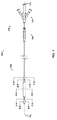
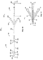
- one embodiment of the catheter assembly (100) comprises a catheter (150) extending from a proximal end adapter (110) and longitudinally movable within a vessel (10) (see FIGS. 12A and 12B ) along the catheter longitudinal axis (170).
- Catheter (150) includes elongate catheter shaft (160) having longitudinal axis (170) and defining five lumens therein.
- the catheter assembly (100) has an atraumatic tapered distal tip (200).
- a distal occluding balloon (210) is located proximal to the tapered distal tip (200) along the longitudinal axis (170) of the catheter (150)
- a space-occupying balloon (230) is located proximal to the distal occluding balloon (210) along the longitudinal axis (170) of the catheter (150)
- a proximal occluding balloon (250) is located proximal to the space-occupying balloon (230) along the longitudinal axis (170) of the catheter (150).
- Proximal end adapter (110) includes occluding balloon inflation hub (120) and delivery hub (130).
- occluding balloon inflation hub (120) comprises distal and proximal occluding balloon inflation port (510) and space-occupying balloon inflation port (530).
- Distal and proximal occluding balloon inflation port (510) communicates with distal and proximal occluding balloon inflation lumen (310) via skive port (610), and permits distal and proximal occluding balloons (210 and 250, respectively), discussed below, to be inflated and deflated - in tandem - during use.
- Space-occupying balloon inflation port (530) communicates with space occupying balloon inflation lumen (330) via skive port (630), and permits space-occupying balloon (230), discussed below, to be inflated and deflated - independently of the distal and proximal occluding balloons - during use.
- therapeutic agent perfusion/aspiration and guidewire hub (the “perfusion/aspiration hub,” 130) comprises therapeutic agent delivery port (540), therapeutic agent aspiration port (520), and guidewire port (500).
- Therapeutic agent delivery port (540) communicates with therapeutic agent delivery lumen (340) via skive port (640), and permits delivery of therapeutic agent via skive port (440) to the lumen (18) of a blood vessel (10).
- Therapeutic agent aspiration port (520) communicates with aspiration lumen (320) via skive port (620), and permits aspiration of therapeutic agents or fluid samples via skive port (420) from the lumen (18) of a blood vessel (10) (see, e.g., FIG. 12B ).
- Guidewire port (500) is in communication with guidewire lumen (300), which extends the entire length of the catheter (150) to emerge at atraumatic tapered tip (200) as distal opening (202), and permits "over-the-wire” use.
- the catheter (100) may be either longer or shorter so that the distal end (140) may reach the desired location within a patient while the proximal end adapter (110) remains outside the patient.
- the catheter (180) possesses three lumens (300, 320, 340).
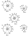
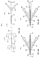
- FIG. 3 is a cross-sectional view of the catheter of FIG. 1 taken along line B - B, and illustrates: distal occluding balloon (210); guidewire lumen (300), which communicates with guidewire port (500); distal and proximal occluding balloon inflation lumen (310), which communicates with occlusion balloon inflation port (510) via skive port (610); space occupying balloon inflation lumen (330), which communicates with space-occupying balloon inflation port (530) via skive port (630); aspiration lumen (320), which communicates with aspiration port (520) via skive port (620); therapeutic agent delivery lumen (340), which communicates with drug delivery port (540) via skive port (640); and distal occluding balloon inflation skive port (410).
- Distal occluding balloon inflation skive port (410) extends through the thickness of the catheter exterior wall (380) such that occluding balloon inflation lumen (310) of the catheter (150) is in communication with the catheter exterior wall (380) for inflating the distal occluding balloon (210).
- FIG. 4 is a cross-sectional view of the catheter of FIG. 1 taken along line C - C, and illustrates a cross-sectional view of the therapeutic agent aspiration segment (220). Referring now to FIGS. 1 , 2 , 4 , 9 , and 11 , FIG. 4 is a cross-sectional view of the catheter of FIG. 1 taken along line C - C, and illustrates a cross-sectional view of the therapeutic agent aspiration segment (220). Referring now to FIGS. 1 , 2 , 4 , 9 , and 11 , FIG.
- Aspiration skive port (420) extends through the thickness of the catheter exterior wall (380) such that aspiration lumen (320) of the catheter (150) is in communication with the catheter exterior wall (380) for aspirating therapeutic agents or liquid samples from the lumen (18) of a blood vessel (10) (see, e.g., FIGS. 12A and 12B ).
- FIG. 5 is a cross-sectional view of the catheter of FIG. 1 taken along line D - D, and illustrates: space-occupying balloon (230); guidewire lumen (300), which communicates with guidewire port (500); distal and proximal occluding balloon inflation lumen (310), which communicates with occlusion balloon inflation port (510) via skive port (610); space occupying balloon inflation lumen (330), which communicates with space-occupying balloon inflation port (530) via skive port (630); aspiration lumen (320), which communicates with aspiration port (520) via skive port (620); therapeutic agent delivery lumen (340), which communicates with drug delivery port (540) via skive port (640); and space-occupying balloon inflation skive port (430).
- Space-occupying balloon inflation skive port (430) extends through the thickness of the catheter exterior wall (380) such that space-occupying balloon inflation lumen (330) of the catheter (150) is in communication with the catheter exterior wall (380) for inflating and deflating the space occupying balloon (230).
- FIG. 6 is a cross-sectional view of the catheter of FIG. 1 taken along line E - E, and illustrates a cross-sectional view of the therapeutic agent delivery segment (240). Referring now to FIGS. 1 , 2 , 6 , 9 , and 11 , FIG.
- Drug delivery skive port (440) extends through the thickness of the catheter exterior wall (380) such that drug delivery lumen (340) of the catheter (150) is in communication with the catheter exterior wall (380) for delivering therapeutic agents to the lumen (18) of a blood vessel (10) (see, e.g., FIGS. 12A and 12B ).
- FIG. 7 is a cross-sectional view of the catheter of FIG. 1 taken along line F - F.
- FIG. 7 illustrates: proximal occluding balloon (250); guidewire lumen (300), which communicates with guidewire port (500); distal and proximal occluding balloon inflation lumen (310), which communicates with occlusion balloon inflation port (510) via skive port (610); space occupying balloon inflation lumen (330), which communicates with space-occupying balloon inflation port (530) via skive port (630); aspiration lumen (320), which communicates with aspiration port (520) via skive port (620); therapeutic agent delivery lumen (340), which communicates with drug delivery port (540) via skive port (640); and proximal occluding balloon inflation skive port (450).
- Proximal occluding balloon inflation skive port (450) extends through the thickness of the catheter exterior wall (380) such that occluding balloon inflation lumen (310) of the catheter (150) is in communication with the catheter exterior wall (380) for inflating the proximal occluding balloon (250).
- the catheter (160) has a catheter exterior wall (380) and a catheter interior wall (390).
- the catheter interior wall (390) defines the guide wire lumen (300).
- Lumens (330, 340, 310, 320) are peripheral to guidewire lumen (300); they are formed within the catheter (150) and located between the catheter interior wall (390) and the catheter exterior wall (380).
- the five lumens (300, 310, 340, 330, 320) extend longitudinally through the catheter (150), interconnecting the open proximal end (500, 510, 540, 530, and 520, respectively) with the open distal end (202, 410/450, 440, 430, and 420, respectively).
- balloon inflation hub (120) is a component of the proximal end adapter (110), lying proximal to the distal end (140) and distal to the therapeutic agent perfusion/aspiration and guidewire hub (130). It will be appreciated by those of ordinary skill in the art that the positions of the balloon inflation hub (120) and the therapeutic agent perfusion/aspiration and guidewire hub (130) may be reversed with respect to one another so that the therapeutic agent perfusion/aspiration and guidewire hub (130) lies between the distal end (140) and the balloon inflation hub (120).
- the balloon inflation hub (120) is comprised of occlusion balloon inflation port (510), space occupying balloon inflation port (530), and catheter shaft (160).
- Occlusion balloon inflation port (510) is communicably connected to occlusion balloon inflation lumen (310) of catheter shaft (160) via occlusion balloons hub inflation skive (610).
- Space occupying balloon inflation port (530) is communicably connected to space occupying balloon inflation lumen (330) of catheter shaft (160) via space occupying balloon hub inflation skive (630).
- therapeutic agent perfusion/aspiration and guidewire hub (130) is a component of the proximal end adapter (110), lying proximal to the distal end (140) and proximal to the balloon inflation hub (120).
- the therapeutic agent perfusion/aspiration and guidewire hub (130) is comprised of therapeutic agent perfusion port (540), aspiration port (520), guidewire port (500), and catheter shaft (160).
- Therapeutic agent perfusion port (540) is communicably connected to therapeutic agent perfusion lumen (340) of catheter shaft (160) via perfusion hub skive (640).
- Aspiration port (520) is communicably connected to aspiration lumen (320) of catheter shaft (160) via aspiration hub skive (620).
- Guidewire port (500) is communicably connected to guidewire lumen (300), which encloses the longitudinal axis (170) of the OPC (100).
- the longitudinal axis (170) is centered within the circular cross-section of the guidewire lumen (300).
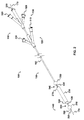
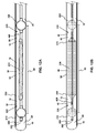
- FIGS. 12A and 12B show the distal and proximal occlusion balloons (210, 250) as they would appear when inflated inside a vessel (10) or other hollow body structure.
- occluding balloons (210, 250), space-occupying balloon (230), catheter (150, 160), and other components of the device of the present disclosure (100) may be sized appropriately to account for the dimensions that would be required in other hollow body structures (for example, but without intending to be limited, vessels of the lymphatic system, the gastroesophageal tract, the portal-caval system of the liver, the gall bladder and bile ducts, the urinary system, the respiratory system, ducts of the endocrine and exocrine organs, and reproductive organs).
- FIGS. 12A and 12B show space-occupying balloon (230) as it would appear before inflation and after inflation, respectively.
- distal and proximal radio-opaque marker bands are also shown located on the "shoulders" of the space-occupying balloon (230) to facilitate visualization, under fluoroscopic imaging, of the catheter (150) within a vessel (10).
- radio-opaque markers may also be located upon the catheter shaft (for example, and without limitation, along the aspiration segment (220) or the therapeutic agent delivery segment (240).
- one of the marker bands is located on the shaft (150) at the most distal portion of the aspiration segment (220), and a second marker band is located on the shaft (150) at the most proximal portion of the therapeutic agent delivery segment (240).
- one of the marker bands is located on the shaft (150) at or near distal occlusion balloon inflation skive ( FIG. 3 , 410), and a second marker band is located on the shaft (150) at or near proximal occluding balloon inflation skive ( FIG. 7 , 450).
- the gap between the two radio-opaque marker bands aids in approximating the treatment volume and treatment location.
- the marker bands (260, 270) may optionally be rotationally specific (e.g., having a generally "U-shaped" configuration) so that the rotational position of the distal end (140) of the catheter (150) will be apparent when the markers are observed in a two-dimensional fluoroscopic image.
- contrast fluid may be used to inflate any one or all of the balloons (210, 230, and/or 250), or may be injected through drug delivery skive port (440) or through guidewire lumen (300) to emerge at the distal tapered tip (200) from the opening (202).
- Subsequent inflation of the space occupying balloon (230), as shown in FIG 12B reduces the intraluminal volume exterior to the balloons to produce occlusion of a comparatively small intraluminal space (40), and thus reduces the treatment volume of the targeted vessel segment (60).
- treatment volume is meant the volume of the vessel, between the expanded occlusion balloons (210, 250), minus the volume of the space-occupying balloon (230). Consequently, deflation of the space-occupying balloon leads to increased treatment volume while inflation of the space-occupying balloon reduces the treatment volume.
- fluid communication between therapeutic agent delivery segment (240) and aspiration segment (220) is maintained (40) despite inflation of space-occupying balloon (230) because the balloon (230) is not in contact with vessel endothelium (50).
- the longitudinal axis (170) is contained within the guide wire lumen (300), but persons having ordinary skill in the art will recognize that the arrangement of lumens may be altered to offset the central lumen (300) from the longitudinal axis (170).
- Lumens (330, 340, 310, and 320) are formed within the catheter (150) and are located substantially between the catheter exterior wall (380) and the catheter interior wall (390).
- the lumens (300, 330, 340, 310, and 320) extend longitudinally through the catheter (150), but only guidewire lumen (300) is patent along the entire length of the catheter (150), emerging at the distal tapered tip (200) as opening (202) and so allowing "over-the-wire” use.
- Inflation of the distal occluding balloon (210) and the proximal occluding balloon (250) creates a substantially cylindrical delivery region bounded distally and proximally by the inflated distal and proximal occluding balloons (210 and 250, respectively) and bounded circumferentially by vessel (10), as shown in FIG. 12A .
- Distal and proximal occluding balloons are constructed of a compliant to semi-compliant material (e.g., without limitation, polyethylene terephthalate, nylon, polyurethane, or other thermoplastic polymers), which means that they retain their shape as they generate force and form a seal against blood flow without imparting excessive pressure to the blood vessel.
- a compliant to semi-compliant material e.g., without limitation, polyethylene terephthalate, nylon, polyurethane, or other thermoplastic polymers
- the space occupying balloon (230) is constructed of a non-compliant to semi-compliant material (e.g., without limitation, polyurethane, nylon elastomers, polyethylene terephthalate, or other thermoplastic polymers).
- a non-compliant to semi-compliant material e.g., without limitation, polyurethane, nylon elastomers, polyethylene terephthalate, or other thermoplastic polymers.
- the space-occupying balloon (230) is inflated to a degree that it does not contact the vessel endothelium (50), thus leaving the entire region of endothelium (50) between the inflated distal and proximal occluding balloons (210 and 250, respectively) available for exposure to the delivered agent.
- the guide wire lumen (300) provides access to a guidewire (not shown), via distal opening (202) in atraumatic tapered tip (200), while distal and proximal occluding balloon inflation lumen (310) and space-occupying balloon inflation lumen (330) provide access for balloon inflation ports (510 and 530, respectively) for the distal (210) and proximal (250) occluding balloons and for the space-occupying balloon (230), respectively.
- Agent delivery port (540) is in communication with agent delivery lumen (340) via skive port (640), and agent delivery lumen (340) is also in communication with vessel lumen (18) via skive port (440) at agent delivery segment (240), for the delivery of therapeutic agents to the occluded vessel lumen (18, 30, 40).
- Aspiration port (520) is in communication with aspiration lumen (320) via skive port (620), and aspiration lumen (320) is in communication with vessel lumen (18) via skive port (420) at aspiration segment (220), for aspiration of agents or other fluid samples from the vessel lumen (18, 30, 40).
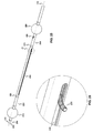
- a two- or three-way valve or check valve (710) in fluid communication with the agent delivery lumen (340), the aspiration lumen (320, as shown in FIGS. 16 and 17 ), or both, to prevent injection via the aspiration lumen (320), aspiration or backflow via the agent delivery lumen (340), or both (respectively).
- the catheter (100) may include a first pressure sensing means (700), as seen in FIGS. 13-15 and 18 , incorporated into the catheter shaft (190, 192) and hub (130a) of the adapter (110).
- a suitable pressure sensing means (700) is the FOP-MIV (Sequoia Technology, Ltd.; Reading, UK) - a fiber optic pressure sensor.
- Such pressure sensing means has a distal end (702), a proximal end (701) located at pressure sensor connector (550), and a length therebetween.
- the pressure sensing means enters therapeutic agent perfusion lumen (340) and extends to a position at or near perfusion/delivery skive (440) at therapeutic agent delivery segment (240), as shown in FIG. 14 .
- therapeutic agent delivery lumen (340) of the catheter (150) is in communication with the catheter exterior wall (380) for delivering therapeutic agents to the lumen (18, 30, 40) of a blood vessel (10), as seen in FIGS. 12A and 12B .
- the pressure sensing means distal end (702) is in communication with the treatment region (60).
- a two- or three-way valve or check valve (710) in line with the agent delivery lumen (340), the aspiration lumen (320, via aspiration port (520), as shown in FIGS. 16-17 ), or both, to prevent injection via the aspiration lumen (320), aspiration or backflow via the agent delivery lumen (340), or both (respectively).
- the two- or three-way valve or check valve (710) is shown attached to the aspiration port (520).
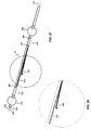
- the catheter (100) may also be constructed so that first pressure sensing means (700) occupies its own separate and dedicated lumen within the catheter (150), and having a proximal opening at pressure sensor connector (550) and distal opening at or near perfusion/delivery skive (440). Between therapeutic agent perfusion/aspiration/guidewire/pressure sensor hub (130a) and occluding balloon inflation hub (120), as indicated by FIGS. 15 and 18 , the catheter (190) possesses three lumens (300, 320, 340), but may possess a dedicated lumen to house the first pressure sensor (700).
- the catheter (100) of the present disclosure may further comprise a second pressure sensing means (704) incorporated into the catheter shaft (190, 192) and hub (130a) of the adapter (110), whereby the pressure of the fluid environment within the therapeutic agent perfusion lumen (340) - at or near the perfusion skive (640), or at any point within the therapeutic agent perfusion lumen (340) - can be known or estimated.
- a second pressure sensing means 704 incorporated into the catheter shaft (190, 192) and hub (130a) of the adapter (110)
- the second pressure sensing means (704) may be located alongside the proximal end of the first pressure sensing means (700), with the second pressure sensing means proximal end (705) also located at the pressure sensor connector (550), but with its distal end (706) located within the therapeutic agent perfusion lumen (340) at or near the perfusion skive (640), or at any point within the therapeutic agent perfusion lumen (340).
- a pressure sensor suitable for this embodiment is the FOP-MIV (Sequoia Technology, Ltd.; Reading, UK) - a fiber optic pressure sensor.
- a user of the device (100) can know or estimate the pressure experienced by a therapeutic agent at or near the perfusion skive (640). Such information may be particularly relevant for the delivery of such agents as live cell suspensions or other materials that may be susceptible to pressure and/or shear stress.
- a two- or three-way valve or check valve (710) in line with the agent delivery lumen (340), the aspiration lumen (320, via aspiration port (520), as shown in FIGS. 16-17 ), or both, to prevent injection via the aspiration lumen (320), aspiration or backflow via the agent delivery lumen (340), or both (respectively).
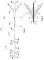
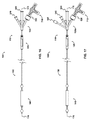
- an embodiment of the catheter assembly (105) comprises a catheter (150) extending from a proximal end adapter (110) and longitudinally movable within a vessel (10) along the catheter longitudinal axis (170).
- Catheter (150) includes elongate catheter shaft (160) having longitudinal axis (170) and defining five lumens therein.
- the catheter assembly (105) has an atraumatic tapered distal tip (200).
- a distal occluding balloon (210) is located proximal to the tapered distal tip (200) along the longitudinal axis (170) of the catheter (150)
- a visualization means slot (435) is located proximal to the distal occluding balloon (210) along the longitudinal axis (170) of the catheter (150)
- a proximal occluding balloon (250) is located proximal to the visualization means slot (435) along the longitudinal axis (170) of the catheter (150).
- Proximal end adapter (110) includes balloon inflation/visualization & illumination means hub (125) and delivery hub (130).
- balloon inflation/visualization & illumination means hub (125) comprises distal and proximal occluding balloon inflation port (510) and visualization means port (535) ( see, e.g., FIG. 19B ).
- Distal and proximal occluding balloon inflation port (510) communicates with distal and proximal occluding balloon inflation lumen (310) via skive port (610), and permits distal and proximal occluding balloons (210 and 250, respectively), discussed below, to be inflated and deflated - in tandem - during use.
- Visualization means port (535) communicates with visualization means lumen (335) via skive port (635), and permits the visualization means (235), discussed below, to pass through the visualization means lumen (335) to reach and emerge from the visualization means slot (435).
- the visualization means port (535) may further comprise a valve (710) (e . g ., a Tuohy Borst adapter, a two-way, three-way, or check valve, etc.) to prevent backflow via the visualization means lumen (335).
- the visualization means (235) further comprises output (238), whereby the visualization means (235) may convey information (e.g., to a monitor, a computer, etc.), which may be visualized and/or recorded by means readily available and known in the art.
- therapeutic agent perfusion/aspiration and guidewire hub (the "perfusion/aspiration hub," 130) comprises therapeutic agent delivery port (540), therapeutic agent aspiration port (520), and guidewire port (500) ( see, e.g., FIG. 19C ).
- Therapeutic agent delivery port (540) communicates with therapeutic agent delivery lumen (340) via skive port (640), and permits delivery of therapeutic agent via skive port (440) to the lumen (18) of a blood vessel (10) ( see, e.g., FIGS. 12A & 12B ).
- Therapeutic agent aspiration port (520) communicates with aspiration lumen (320) via skive port (620), and permits aspiration of therapeutic agents or fluid samples via skive port (420) from the lumen (18) of a blood vessel (10) ( see, e.g., FIGS. 12A & 12B ).
- Guidewire port (500) is in communication with guidewire lumen (300), which extends the entire length of the catheter (150) to emerge at atraumatic tapered tip (200) as distal opening (202), and permits "over-the-wire” use.
- guidewire lumen (300) which extends the entire length of the catheter (150) to emerge at atraumatic tapered tip (200) as distal opening (202), and permits "over-the-wire” use.
- the catheter (105) may be either longer or shorter so that the distal end (140) may reach the desired location within a patient while the proximal end adapter (110) remains outside the patient.
- the catheter (180) possesses three lumens (300, 320, 340).
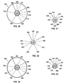
- FIG. 20 is a cross-sectional view of the catheter of FIG. 19 taken along line I - I, and illustrates: distal occluding balloon (210); guidewire lumen (300), which communicates with guidewire port (500); distal and proximal occluding balloon inflation lumen (310), which communicates with occlusion balloon inflation port (510) via skive port (610); visualization means lumen (335), which communicates with visualization means port (535) via skive port (635); aspiration lumen (320), which communicates with aspiration port (520) via skive port (620); therapeutic agent delivery lumen (340), which communicates with drug delivery port (540) via skive port (640); and distal occluding balloon inflation skive port (410).
- Distal occluding balloon inflation skive port (410) extends through the thickness of the catheter exterior wall (380) such that occluding balloon inflation lumen (310) of the catheter (150) is in communication with the catheter exterior wall (380) for inflating the distal occluding balloon (210).
- FIG. 21 is a cross-sectional view of the catheter of FIG. 19 taken along line J - J, and illustrates a cross-sectional view of the therapeutic agent aspiration segment (220), showing: guidewire lumen (300), which communicates with guidewire port (500); distal and proximal occluding balloon inflation lumen (310), which communicates with occlusion balloon inflation port (510) via skive port (610); visualization means lumen (335), which communicates with visualization means port (535) via skive port (635); aspiration lumen (320), which communicates with aspiration port (520) via skive port (620); therapeutic agent delivery lumen (340), which communicates with perfusion port (540) via skive port (640); and aspiration skive port (420).
- Aspiration skive port (420) extends through the thickness of the catheter exterior wall (380) such that aspiration lumen (320) of the catheter (150) is in communication with the catheter exterior wall (380) for aspirating therapeutic agents or liquid samples from the lumen (18) of a blood vessel (10) ( see, e.g., FIGS. 12A and 12B ).
- FIG. 22 is a cross-sectional view of the catheter of FIG. 19 taken along line K - K, and illustrates: guidewire lumen (300), which communicates with guidewire port (500); distal and proximal occluding balloon inflation lumen (310), which communicates with occlusion balloon inflation port (510) via skive port (610); visualization means (235) contained within visualization means lumen (335), which communicates with visualization means port (535) via skive port (635); aspiration lumen (320), which communicates with aspiration port (520) via skive port (620); therapeutic agent delivery lumen (340), which communicates with drug delivery port (540) via skive port (640); and space-occupying balloon inflation skive port (430).
- guidewire lumen (300) which communicates with guidewire port (500); distal and proximal occluding balloon inflation lumen (310), which communicates with occlusion balloon inflation port (510) via skive port (610); visualization means (235) contained within visualization means lumen (335
- Visualization means slot (435) extends through the thickness of the catheter exterior wall (380) such that visualization means lumen (335) of the catheter (150) is in communication with the catheter exterior wall (380) for allowing the visualization means (235) to exit the visualization means slot (435) and lumen (335) and enter the lumen (18) of a blood vessel (10).
- Visualization means slot (435) extends parallel to the longitudinal axis (170) and between aspiration segment (220) and therapeutic agent delivery segment (240) for a length sufficient to allow the visualization means (235) to exit the visualization means slot (435), as shown in FIGS. 27 and 28 .
- the visualization means (235) enables visualization of the vessel lumen in a 360° radius (that is, all of the vessel inner wall, without the view being obstructed by the catheter itself).
- FIG. 23 is a cross-sectional view of the catheter of FIG. 19 taken along line L - L, and shows: guidewire lumen (300), which communicates with guidewire port (500); distal and proximal occluding balloon inflation lumen (310), which communicates with occlusion balloon inflation port (510) via skive port (610); visualization means (235) contained within visualization means lumen (335), which communicates with visualization means port (535) via skive port (635); aspiration lumen (320), which communicates with aspiration port (520) via skive port (620); therapeutic agent delivery lumen (340), which communicates with perfusion port (540) via skive port (640); and drug delivery skive port (440).
- guidewire lumen (300) which communicates with guidewire port (500); distal and proximal occluding balloon inflation lumen (310), which communicates with occlusion balloon inflation port (510) via skive port (610); visualization means (235) contained within visualization means lumen (335), which communicates with
- Drug delivery skive port (440) extends through the thickness of the catheter exterior wall (380) such that drug delivery lumen (340) of the catheter (150) is in communication with the catheter exterior wall (380) for delivering therapeutic agents to the lumen (18) of a blood vessel (10) ( see, e.g., FIGS. 12A and 12B ).
- FIG. 24 is a cross-sectional view of the catheter of FIG. 19 taken along line M - M, and shows: proximal occluding balloon (250); guidewire lumen (300), which communicates with guidewire port (500); distal and proximal occluding balloon inflation lumen (310), which communicates with occlusion balloon inflation port (510) via skive port (610); visualization means (235) contained within visualization means lumen (335), which communicates with visualization means port (535) via skive port (635); aspiration lumen (320), which communicates with aspiration port (520) via skive port (620); therapeutic agent delivery lumen (340), which communicates with drug delivery port (540) via skive port (640); and proximal occluding balloon inflation skive port (450).
- Proximal occluding balloon inflation skive port (450) extends through the thickness of the catheter exterior wall (380) such that occluding balloon inflation lumen (310) of the catheter (150) is in communication with the catheter exterior wall (380) for inflating the proximal occluding balloon (250).
- the catheter (160) has a catheter exterior wall (380) and a catheter interior wall (390).
- the catheter interior wall (390) defines the guide wire lumen (300).
- Lumens (335, 340, 310, 320) are peripheral to guidewire lumen (300); they are formed within the catheter (150) and located between the catheter interior wall (390) and the catheter exterior wall (380).
- the five lumens (300, 310, 340, 335, 320) extend longitudinally through the catheter (150), interconnecting the open proximal end (500, 510, 540, 535, and 520, respectively) with the open distal end (202, 410/450, 440, 435, and 420, respectively).
- balloon inflation/visualization & illumination means hub (125) is a component of the proximal end adapter (110), lying proximal to the distal end (140) and distal to the therapeutic agent perfusion/aspiration and guidewire hub (130). It will be appreciated by those of ordinary skill in the art that the positions of the balloon inflation/visualization & illumination means hub (125) and the therapeutic agent perfusion/aspiration and guidewire hub (130) may be reversed with respect to one another so that the therapeutic agent perfusion/aspiration and guidewire hub (130) lies between the distal end (140) and the balloon inflation/visualization & illumination means hub (125).
- the balloon inflation/visualization & illumination means hub (125) is comprised of occlusion balloon inflation port (510), visualization means port (535), and catheter shaft (160).
- Occlusion balloon inflation port (510) is communicably connected to occlusion balloon inflation lumen (310) of catheter shaft (160) via occlusion balloons hub inflation skive (610).
- Visualization means port (535) is communicably connected to visualization means lumen (335) of catheter shaft (160) via skive port (635).
- therapeutic agent perfusion/aspiration and guidewire hub (130) is a component of the proximal end adapter (110), lying proximal to the distal end (140) and proximal to the balloon inflation/visualization & illumination means hub (125).
- the therapeutic agent perfusion/aspiration and guidewire hub (130) is comprised of therapeutic agent perfusion port (540), aspiration port (520), guidewire port (500), and catheter shaft (160).
- Therapeutic agent perfusion port (540) is communicably connected to therapeutic agent perfusion lumen (340) of catheter shaft (160) via perfusion hub skive (640).
- Aspiration port (520) is communicably connected to aspiration lumen (320) of catheter shaft (160) via aspiration hub skive (620).
- Guidewire port (500) is communicably connected to guidewire lumen (300), which encloses the longitudinal axis (170) of the OVC (105). In the present embodiment, and as shown in FIGS. 20-24 , the longitudinal axis (170) is centered within the circular cross-section of the guidewire lumen (300).
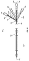
- FIGS. 25-28 and 12B show the distal and proximal occlusion balloons (210, 250) as they would appear when inflated inside a vessel (10) or other hollow body structure, and show the visualization means (235) as it would appear as it exits the visualization means slot (435).
- occluding balloons may be sized appropriately to account for the dimensions that would be required in other hollow body structures (for example, but without intending to be limited, vessels of the lymphatic system, the gastroesophageal tract, the portal-caval system of the liver, the gall bladder and bile ducts, the urinary system, the respiratory system, ducts of the endocrine and exocrine organs, and reproductive organs).
- vessels of the lymphatic system for example, but without intending to be limited, vessels of the lymphatic system, the gastroesophageal tract, the portal-caval system of the liver, the gall bladder and bile ducts, the urinary system, the respiratory system, ducts of the endocrine and exocrine organs, and reproductive organs.
- radio-opaque marker bands are also shown located on the catheter distal end (140) to facilitate visualization, under fluoroscopic imaging, of the device (105) within a vessel (10). It will be appreciated by those of ordinary skill in the art that radio-opaque markers may also be located upon other portions of the device (105), for example, and without limitation, along the aspiration segment (220), the therapeutic agent delivery segment (240), the occlusion balloons (210, 250), and as described above for the OPC (100).
- contrast fluid may be used to inflate the occlusion balloons (210, 250), or may be injected through drug delivery skive port (440) or through guidewire lumen (300) to emerge at the distal tapered tip (200) from the opening (202).
- the visualization means (235) may exit the visualization means slot (435) at the slot's most proximal end.
- the visualization means (235) may, optionally, comprise a bend at its most distal end to facilitate exit from the visualization means lumen (335) and visualization means slot (435).
- the visualization means (235) may further exit the visualization means lumen (335) via the visualization means slot (435) so that the visualization means (235) distal end lies further from the longitudinal axis (170).
- the visualization means may turn about the longitudinal axis (170) and so enables visualization of the entire vessel lumen surrounding the device and between the occluding balloons (210, 250).
- Inflation of the distal occluding balloon (210) and the proximal occluding balloon (250) creates a substantially cylindrical visualization region bounded distally and proximally by the inflated distal and proximal occluding balloons (210 and 250, respectively) and bounded circumferentially by vessel (10), as shown, for example, in FIG. 12A .
- the longitudinal axis (170) is contained within the guide wire lumen (300), but persons having ordinary skill in the art will recognize that the arrangement of lumens may be altered to offset the central lumen (300) from the longitudinal axis (170).
- Lumens (335, 340, 310, and 320) are formed within the catheter (150) and are located substantially between the catheter exterior wall (380) and the catheter interior wall (390).
- the lumens (300, 335, 340, 310, and 320) extend longitudinally through the catheter (150), but only guidewire lumen (300) is patent along the entire length of the catheter (150), emerging at the distal tapered tip (200) as opening (202) and so allowing "over-the-wire" use.
- the catheter (105) may further comprise one or more two-or three-way valves or check valves (710) in fluid communication with the agent delivery lumen (340), the aspiration lumen (320), the visualization means lumen (335) or all three, to prevent injection via the aspiration lumen (320), aspiration or backflow via the agent delivery lumen (340), backflow via the visualization means lumen (335) or all three (respectively).
- a one-way check valve e . g ., a Tuohy-Borst adapter, 710) may be used to prevent backflow via the visualization means lumen (335).
- the OVC catheter (105) may include a first pressure sensing means incorporated into the catheter shaft and therapeutic agent perfusion/aspiration/guide wire hub of the adapter (110), as shown and described above for the OPC (100).
- a suitable pressure sensing means is the FOP-MIV (Sequoia Technology, Ltd.; Reading, UK) - a fiber optic pressure sensor.
- the OVC catheter (105) of the present disclosure may further comprise a second pressure sensing means incorporated into the catheter shaft and therapeutic agent perfusion/aspiration/guide wire hub of the adapter (110), as shown and described above for the OPC (100), whereby the pressure of the fluid environment within the therapeutic agent perfusion lumen (340) - at or near the perfusion skive (640), or at any point within the therapeutic agent perfusion lumen (340) - can be known or estimated.
- the catheter (100) can be used with a guide wire (not shown), via guide wire lumen (300), to assist in guiding the catheter (100) to the target segment (60) of the vessel (10).
- the catheter shafts (150) of the present disclosure are preferably between about 2-7 French units ("Fr.” where one French equals 1/3 of a millimeter, or about 0.013 inches).
- the catheter shafts to be used in coronary arteries are preferably between about 3-5 Fr. in diameter, and most preferably about 3 Fr.
- the catheter shafts to be used in peripheral vessels are preferably between about 5-8 Fr. in diameter, and most preferably 5 Fr.
- the catheter shafts can be made of materials including, but not limited to polymers, natural or synthetic rubber, metal and plastic or combinations thereof, nylon, Pebax, nylon/Pebax blend, Hytrel ® and polyethylene.
- the shaft materials can be selected so as to maximize column strength to the longitudinal length of the shaft. Further, the shaft materials can be braided, so as to provide sufficient column strength.
- the shaft materials can also be selected so as to allow the device to move smoothly along a guide wire.
- the catheter (100) can also be provided with a lubricious coating as well as antimicrobial and antithrombogenic coatings, as are known to those of skill in the art.
- the shaft materials can also be selected so as to maximize bonding of the shaft to the balloon materials.
- the shaft materials should be selected so as not to interfere with the efficacy of the agent to be delivered or collected. This interference may take the form of absorbing the agent, adhering to the agent or altering the agent in any way, for example.
- the balloons can be made of materials including, but not limited to Kraton ® , polyurethane, polyolefin or any other biocompatible, elastometric material, or other soft materials.
- the materials of the balloons may be selected so as to maximize pliability and/or reduce the risk of damage to tissues.
- the balloon materials should be selected so as not to interfere with the efficacy of the agent to be delivered or collected.
- Balloon (210, 230, 250) inflation sources can be syringes in communication with lumens (310, 330) via proximal ports (510, 530), or other inflation sources known to those of ordinary skill in the art.
- the syringes - individually or separately - may contain contrast media or gas or other fluids known to those skilled in the art to be safe and effective for inflating the balloon.
- the distal and proximal occlusion balloons (210, 250) used for coronary arteries are preferably 2 to 4 mm in diameter when inflated.
- the distal and proximal occlusion balloons (210, 250) used for peripheral vessels are preferably 5 to 10 mm in diameter when inflated.
- the distal and proximal occlusion balloons (210, 250) are preferably about 1 to 2 cm in length, and football-shaped or spherical, or any suitable shape that a compliant to semi-compliant balloon can achieve.
- the balloons (210, 250) are most preferably about 1 cm long. However, the length and diameter of the balloons can be selected so as to minimize tissue damage.
- the force exerted against the vessel interior by occlusion balloons (210, 250) is sufficiently great enough to hold the catheter (100) in a stationary position within the vessel or other hollow body structure and provide an adequate seal to control blood or fluid flow. However, the force is not so great as to damage the interior surface of the vessel or other hollow body structure.
- each occlusion balloon (210, 250) is separated from space occupying balloon (230) by about 1 to 10 mm, or more preferably by about 1 to 7 mm, or most preferably by about 1 to 3 mm.
- the distance between the most proximal edge of distal occlusion balloon (210) and the most distal edge of space-occupying balloon (230) defines the aspiration segment (220) length; the distance between the most distal edge of proximal occlusion balloon (250) and the most proximal edge of space-occupying balloon (230) defines the therapeutic agent delivery segment (240) length.
- the aspiration and therapeutic agent delivery segment lengths are preferably about 1 to 10 mm, or more preferably about 1 to 7 mm, or most preferably about 1 to 3 mm.
- the guide wire When using a guide wire, whether the catheter (100) is being used in the coronary arteries or in the peripheral vasculature, the guide wire is preferably about 0.014 to 0.018 inches in diameter.
- Therapeutic agents useful with the device of the present disclosure include any one of or a combination of several agents which are gas, liquid, suspensions, emulsions, or solids, which may be delivered or collected from the vessel for therapeutic or diagnostic purposes.
- Therapeutic agents include biologically active substances, or substances capable of eliciting a biological response, including, but not limited to endogenous substances (growth factors or cytokines, including, but not limited to basic fibroblast growth factor, acidic fibroblast growth factor, vascular endothelial growth factor, angiogenic factors), viral vectors, DNA capable of expressing proteins, sustained release polymers, and unmodified or modified cells.
- Therapeutic agents can include angiogenic agents which induce the formation of new blood vessels.
- Therapeutic agents can also include anti-stenosis or anti-restenosis agents which are used to treat the narrowing of blood vessel walls.
- the rate of therapeutic agent delivery to the targeted vessel segment (60), as shown in FIGS. 12A and 12B can be selected so as to minimize tissue damage.
- the rate of therapeutic agent delivery can depend upon at least the size of perfusion/delivery skive (440) and the pressure under which the agent is passed through the skive (440).
- the rate of therapeutic agent delivery can be controlled by, for example, an osmotic pump or an infusion pump attached in line with perfusion port (540), perfusion lumen (340), and perfusion skive (440); use of a perfusion pump is also compatible with a two- or three-way valve or check valve appropriately in line with such an arrangement.
- Other target spaces that may be accessed by the catheter (100) include but are not limited to any other hollow viscera of the body such as: any of the blood vessels of the cardiovascular system (arteries and veins); vessels of the lymphatic system; the gastroesophageal tract; the portal-caval system of the liver; the gall bladder and bile ducts; the urinary system; the respiratory system; ducts of the endocrine and exocrine organs; and reproductive organs.
- any other hollow viscera of the body such as: any of the blood vessels of the cardiovascular system (arteries and veins); vessels of the lymphatic system; the gastroesophageal tract; the portal-caval system of the liver; the gall bladder and bile ducts; the urinary system; the respiratory system; ducts of the endocrine and exocrine organs; and reproductive organs.
- the present disclosure also contemplates a method of using balloon occlusion catheters, such as catheter assembly (100), with or without a pressure sensing means (700 and/or 704), and with or without a two- or three-way or check valve (710), for the delivery and/or the collection of agents from a targeted vessel segment (60) in vivo.
- balloon occlusion catheters such as catheter assembly (100)
- a pressure sensing means 700 and/or 704
- a two- or three-way or check valve (710) for the delivery and/or the collection of agents from a targeted vessel segment (60) in vivo.
- the OPC would be delivered to the treatment site via a minimally invasive insertion technique, over a guidewire, to the treatment area, and the occlusion balloons (210, 250) inflated to isolate the treatment region. Blood and any other fluid trapped between the two inflated occlusion balloons (210, 250) would be aspirated from the treatment region, and the treatment region flushed with saline. The saline would then be aspirated from the treatment region, the space occupying balloon would be inflated, and the agent would be injected into the treatment region.
- the aspiration lumen could be controlled via the proximal two- or three-way stopcock or check valve to allow the agent to enter the treatment region and prevent the agent from exiting the treatment region prematurely, and further allow selected fluid pressures within the treatment region to be achieved.
- the space occupying balloon could be optionally deflated, partially, to allow the injection of more agent, whereupon the space occupying balloon would be re-inflated to achieve a greater pressure within the treatment area and to force the agent into the media of the vessel wall.
- the space occupying balloon would be deflated, the agent would be optionally aspirated from the treatment region, and the treatment region optionally flushed ( e . g ., with saline).
- the occlusion balloons would be deflated and the OPC could be withdrawn from the treatment site.
- the OPC can be repositioned and the steps set forth above repeated.
- the steps set forth herein are susceptible of multiple variations that lie within the scope of the present disclosure (e . g ., the space occupying balloon need not be deflated and then re-inflated, or one may elect not to flush the treatment region).
- the space occupying balloon presents at least two advantages: by taking up space, it decreases the volume of agent required (which is important, given that such agents are generally quite expensive); and it is used to increase pressure within the treatment region, and so push the agent into the media of the vessel wall - the end target of treatment.
- the OPC would be delivered to the treatment site via a minimally invasive insertion technique, over a guidewire, and the occlusion balloons (210, 250) inflated to isolate the treatment region.
- the space occupying balloon (230) would be inflated to minimize the treatment volume, with the displaced blood draining out through the evacuation lumen (320).
- Saline could be used as a flushing agent, or the therapeutic agent could be directly injected in through the perfusion lumen (340), displacing the remainder of the blood.
- a stopcock connected to the device via the evacuation port (520) would be closed, allowing controlled pressure to be built-up in the treatment region with the continued injection of therapeutic agent, resulting in perfusion into the damaged area of the blood vessel/body lumen.
- the stopcock would be opened, and saline would be injected in through the perfusion lumen (340), flushing the treatment region.
- the space occupying balloon (230) and the occlusion balloons (210, 250) would then be deflated, allowing movement or removal of the device.
- the OPC would be delivered to the treatment site via a minimally invasive insertion technique, over a guidewire, and the occlusion balloons (210, 250) inflated to isolate the treatment region.
- the space occupying balloon (230) would be inflated to minimize the treatment volume, with the displaced blood draining out through the evacuation lumen (320). The remainder of the blood is aspirated out through the evacuation lumen (320), creating a vacuum in the treatment region.
- a stopcock attached to the evacuation port (520) would be closed, maintaining the vacuum.
- a two part polymeric agent would be injected into the treatment region - part "A" goes in one port (the perfusion lumen (340) for example), while part “B” goes in through the other (the evacuation lumen (320) for example) so that polymerization takes place in the treatment region.
- saline could be injected in through the evacuation lumen (320) while aspiration is facilitated through the perfusion lumen (340), which due to its larger size, would be more appropriate for removal of a polymerized solution or gel, flushing the treatment region.
- the space occupying balloon (230) and the occlusion balloons (210, 250) would then be deflated, allowing movement or removal of the device.
- This technique may provide an alternative to therapies that might be too time-consuming if the polymer is too thick to otherwise inject in through the lumens directly.
- the OPC would be delivered to the treatment site via a minimally invasive insertion technique, over a guidewire, and the occlusion balloons (210, 250) inflated to isolate the treatment region.
- the space occupying balloon (230) would be inflated to minimize the treatment volume, with the displaced blood draining out through the evacuation lumen (320).
- Saline could be used as a flushing agent, or the therapeutic agent could be directly injected in through the perfusion lumen (340), while the remainder of the blood is simultaneously aspirated out through the evacuation lumen (320).
- a stopcock connected to the device via the evacuation port (520) would be closed, allowing controlled pressure to be built-up in the treatment region with the continued injection of therapeutic agent, resulting in perfusion into the damaged area of the body lumen.
- the stopcock would be opened, and saline would be injected in through the perfusion lumen (340), while aspiration is facilitated through the evacuation lumen (320), flushing the treatment region.
- the space occupying balloon (230) and the occlusion balloons (210, 250) would then be deflated, allowing movement or removal of the device.
- Sequential aspirate out/perfuse in (sequential exchange of fluids in the treatment region).
- the OPC would be delivered to the treatment site via a minimally invasive insertion technique, over a guidewire, and the occlusion balloons (210, 250) inflated to isolate the treatment region.
- the space occupying balloon (230) would be inflated to minimize the treatment volume, with the displaced blood draining out through the evacuation lumen (320). The remainder of the blood is aspirated out through the evacuation lumen (320), creating a vacuum in the treatment region.
- a stopcock attached to the evacuation port (520) would be closed, maintaining the vacuum.
- the stopcock would be opened, and saline would be injected in through the perfusion lumen (340), while aspiration is facilitated through the evacuation lumen (320), flushing the treatment region.
- the space occupying balloon (230) and the occlusion balloons (210, 250) would then be deflated, allowing movement or removal of the device.
- the OVC would be delivered to the treatment site via a minimally invasive insertion technique, over a guidewire, to the treatment area, and the occlusion balloons (210, 250) inflated to isolate the treatment region. Blood and any other fluid trapped between the two inflated occlusion balloons (210, 250) would be aspirated from the treatment region, and the treatment region flushed with saline. Optionally, saline could remain within the treatment region to facilitate visualization.
- the visualization means (235) would be inserted into the visualization lumen (335), permitting visualization of the treatment region. If present, the saline could be aspirated and the occlusion balloons deflated. Then, the OVC could be repositioned or removed. The visualization means (235) could be removed from the visualization lumen (335) at the user's convenience ( e . g ., between repositioning steps, at completion of the procedure, etc.).
- the OVC may also be used as an agent-delivery catheter, wherein the steps for delivering an agent would be the same as for the OPC, but without the steps involving the space-occupying balloon. Pressure to push the agent into the media of the vessel wall could be applied via the agent delivery lumen (340).
Applications Claiming Priority (2)
| Application Number | Priority Date | Filing Date | Title |
|---|---|---|---|
| US11074408P | 2008-11-03 | 2008-11-03 | |
| EP09829691.6A EP2344230B1 (fr) | 2008-11-03 | 2009-11-03 | Cathéter de perfusion d'occlusion |
Related Parent Applications (2)
| Application Number | Title | Priority Date | Filing Date |
|---|---|---|---|
| EP09829691.6A Division EP2344230B1 (fr) | 2008-11-03 | 2009-11-03 | Cathéter de perfusion d'occlusion |
| EP09829691.6A Division-Into EP2344230B1 (fr) | 2008-11-03 | 2009-11-03 | Cathéter de perfusion d'occlusion |
Publications (1)
| Publication Number | Publication Date |
|---|---|
| EP3093039A1 true EP3093039A1 (fr) | 2016-11-16 |
Family
ID=42226351
Family Applications (2)
| Application Number | Title | Priority Date | Filing Date |
|---|---|---|---|
| EP09829691.6A Not-in-force EP2344230B1 (fr) | 2008-11-03 | 2009-11-03 | Cathéter de perfusion d'occlusion |
| EP16162103.2A Withdrawn EP3093039A1 (fr) | 2008-11-03 | 2009-11-03 | Cathéter de perfusion d'occlusion |
Family Applications Before (1)
| Application Number | Title | Priority Date | Filing Date |
|---|---|---|---|
| EP09829691.6A Not-in-force EP2344230B1 (fr) | 2008-11-03 | 2009-11-03 | Cathéter de perfusion d'occlusion |
Country Status (7)
| Country | Link |
|---|---|
| US (6) | US8088103B2 (fr) |
| EP (2) | EP2344230B1 (fr) |
| JP (5) | JP5559804B2 (fr) |
| CN (2) | CN102271747B (fr) |
| BR (1) | BRPI0919884B8 (fr) |
| HK (2) | HK1160046A1 (fr) |
| WO (1) | WO2010062778A2 (fr) |
Families Citing this family (103)
| Publication number | Priority date | Publication date | Assignee | Title |
|---|---|---|---|---|
| WO2014082044A1 (fr) | 2012-11-26 | 2014-05-30 | Spatz Fgia, Inc. | Système et procédés d'internalisation de composants d'un ballonnet intragastrique réglable |
| US9974680B2 (en) | 2004-12-27 | 2018-05-22 | Spatz Fgia, Inc. | System and methods for internalization of external components of adjustable intragastric balloon |
| ITMI20062333A1 (it) * | 2006-12-05 | 2008-06-06 | Mario Salerno | Dispositivo per assistere il trattamento scloresante delle vene varicose |
| US20110208022A1 (en) * | 2008-09-16 | 2011-08-25 | Intersect Partners ,LLC a Limited Liability Corporation | Device and methods for sampling prostate fluid |
| JP5559804B2 (ja) * | 2008-11-03 | 2014-07-23 | アドバンスト・カテーテル・セラピーズ・インコーポレイテッド | 閉塞灌流カテーテル |
| US8226601B2 (en) | 2008-11-12 | 2012-07-24 | Sanovas, Inc. | Resector balloon system |
| US8540667B2 (en) * | 2008-11-12 | 2013-09-24 | Sanovas, Inc. | Multi-balloon catheter for extravasated drug delivery |
| CH700478A1 (de) * | 2009-02-27 | 2010-08-31 | Schwager Medica | Katheter. |
| US20100305678A1 (en) * | 2009-05-27 | 2010-12-02 | Khaldoon Alaswad | Thrombectomy and Balloon Angioplasty/Stenting Device |
| US10512761B2 (en) | 2009-12-02 | 2019-12-24 | Renovorx, Inc. | Methods for delivery of therapeutic materials to treat pancreatic cancer |
| EP2506913B8 (fr) | 2009-12-02 | 2020-11-18 | RenovoRX, Inc. | Dispositifs et ensembles de délivrance de produits thérapeutiques à un pancréas |
| US9457171B2 (en) | 2009-12-02 | 2016-10-04 | Renovorx, Inc. | Devices, methods and kits for delivery of therapeutic materials to a target artery |
| US9539081B2 (en) | 2009-12-02 | 2017-01-10 | Surefire Medical, Inc. | Method of operating a microvalve protection device |
| AU2011242697B2 (en) | 2010-04-21 | 2015-01-22 | Government Of The United States | Fluoroscopy-independent, endovascular aortic occlusion system |
| US8597239B2 (en) * | 2011-03-01 | 2013-12-03 | Sanovas, Inc. | Abrading balloon catheter for extravasated drug delivery |
| US20160074581A1 (en) | 2014-09-17 | 2016-03-17 | Lawrence J. Gerrans | Modulated Drug Delivery |
| CN102125721A (zh) * | 2011-03-10 | 2011-07-20 | 微创医疗器械(上海)有限公司 | 一种新型介入医疗器械 |
| US20120259401A1 (en) * | 2011-04-08 | 2012-10-11 | Gerrans Lawrence J | Balloon catheter for launching drug delivery device |
| JP2012249951A (ja) * | 2011-06-06 | 2012-12-20 | Olympus Corp | 治療装置とその作動方法 |
| CN102302820A (zh) * | 2011-09-13 | 2012-01-04 | 中国人民解放军第四军医大学 | 主动脉腔内灌注管 |
| JP5547149B2 (ja) * | 2011-09-16 | 2014-07-09 | 富士システムズ株式会社 | 封止部材挿入用押圧部材付きガイドワイヤー及び薬液注入用カテーテル装置 |
| EP2846821B1 (fr) | 2012-05-03 | 2020-03-11 | Indiana University Research&Technology Corporation | Procédés hydrodynamiques pour administrer des fluides aux tissus rénaux et matériaux et procédés associés |
| CN103055408B (zh) * | 2012-12-31 | 2016-02-10 | 山东省立医院 | 妇科三囊多腔管 |
| CN103070677B (zh) * | 2012-12-31 | 2014-10-29 | 王青 | 一种兼备采样和药物灌注功能的便携式生理参数遥测装置 |
| US9474882B2 (en) * | 2013-02-26 | 2016-10-25 | Prytime Medical Devices, Inc. | Fluoroscopy-independent balloon guided occlusion catheter and methods |
| US20140275724A1 (en) * | 2013-03-15 | 2014-09-18 | W-Z Biotech, Llc | Percutaneous dual-lumen cannula for cavopulmonary assist device |
| WO2014197362A1 (fr) | 2013-06-03 | 2014-12-11 | Ramtin Agah | Dispositifs, procédés et kit d'administration de substances thérapeutiques à un pancréas |
| AU2014311994A1 (en) * | 2013-08-30 | 2016-04-21 | Indiana University Research & Technology Corporation | Hydrodynamic method and apparatus for delivering fluids to kidney tissues |
| EP3043858B1 (fr) | 2013-09-09 | 2022-11-02 | Prytime Medical Devices, Inc. | Cathéter d'occlusion au profil bas |
| US20170340865A9 (en) * | 2014-03-07 | 2017-11-30 | Translational Biologic Infusion Catheter, Llc | Prolate spheroid-shaped balloon with central hinge |
| US9968740B2 (en) | 2014-03-25 | 2018-05-15 | Surefire Medical, Inc. | Closed tip dynamic microvalve protection device |
| US10278850B2 (en) * | 2014-03-27 | 2019-05-07 | Clever Cath Technologies, LLC | Stent deployment and postdilatation non-compliant balloon catheter and methods of use |
| US9901722B2 (en) | 2014-06-01 | 2018-02-27 | White Swell Medical Ltd | System and method for treatment of pulmonary edema |
| US20150343181A1 (en) | 2014-06-02 | 2015-12-03 | Cook Medical Technologies Llc | Occlusion device and methods of using the same |
| WO2015191685A1 (fr) | 2014-06-10 | 2015-12-17 | Pryor Medical Devices, Inc. | Pointe de guidage dans un passage |
| CN106794328B (zh) * | 2014-10-13 | 2021-12-24 | 爱默蕾大学 | 用于递送治疗性材料的递送装置、系统和方法 |
| KR101669179B1 (ko) * | 2014-12-29 | 2016-10-27 | (의료)길의료재단 | 풍선이 장착된 스텐트 삽입장치 및 이의 사용방법 |
| WO2016149653A2 (fr) | 2015-03-19 | 2016-09-22 | Prytime Medical Devices, Inc. | Système et procédé pour cathéter d'occlusion à ballonnet à faible encombrement |
| EP3273882B1 (fr) | 2015-03-26 | 2020-08-05 | Jeffrey E. Thomas | Cathéter utilisé en cas d'accident vasculaire cérébral destiné à un usage dans le cadre d'opérations de revascularisation |
| US20160287839A1 (en) | 2015-03-31 | 2016-10-06 | Surefire Medical, Inc. | Apparatus and Method for Infusing an Immunotherapy Agent to a Solid Tumor for Treatment |
| US10149684B2 (en) | 2015-05-11 | 2018-12-11 | White Swell Medical Ltd | Systems and methods for reducing pressure at an outflow of a duct |
| US11166729B2 (en) * | 2015-12-22 | 2021-11-09 | Basis Medical, Llc | Method and device for secluding a body vessel |
| WO2017059598A1 (fr) * | 2015-10-10 | 2017-04-13 | 杭州安杰思医学科技有限公司 | Pince hémostatique pour nettoyage des suintements sanguins sur des sites hémorragiques |
| US10716915B2 (en) | 2015-11-23 | 2020-07-21 | Mivi Neuroscience, Inc. | Catheter systems for applying effective suction in remote vessels and thrombectomy procedures facilitated by catheter systems |
| US11571217B2 (en) * | 2015-12-22 | 2023-02-07 | Basis Medical, Llc | Method and device for secluding a body vessel |
| US11433183B2 (en) * | 2018-03-09 | 2022-09-06 | Corflow Therapeutics Ag | System for diagnosing and treating microvascular obstructions |
| US11786140B2 (en) | 2019-08-21 | 2023-10-17 | Corflow Therapeutics Ag | Controlled-flow infusion catheter and method |
| JP6921112B2 (ja) | 2016-01-04 | 2021-08-18 | コルフロウ セラピューティクス アーゲー | Mvoを治療するためのシステムおよび方法 |
| AU2017229996B2 (en) * | 2016-03-11 | 2021-07-01 | Laborie Medical Technologies Corp. | Pressure catheter device |
| US20170281914A1 (en) | 2016-03-31 | 2017-10-05 | Surmodics, Inc. | Localized treatment of tissues through transcatheter delivery of active agents |
| JP6408176B2 (ja) | 2016-06-02 | 2018-10-17 | プリタイム・メディカル・デバイシーズ・インコーポレイテッドPrytime Medical Devices,Inc. | 低プロファイル閉塞バルーンカテーテル用のシステムおよび方法 |
| TWI584836B (zh) * | 2016-06-17 | 2017-06-01 | 貝克生醫股份有限公司 | 一種導管裝置及近接治療系統 |
| CN106178164A (zh) * | 2016-08-30 | 2016-12-07 | 崔勇 | 具有内阻断功能的顺行主动脉灌注管、应用及使用方法 |
| US11400263B1 (en) | 2016-09-19 | 2022-08-02 | Trisalus Life Sciences, Inc. | System and method for selective pressure-controlled therapeutic delivery |
| US10780250B1 (en) | 2016-09-19 | 2020-09-22 | Surefire Medical, Inc. | System and method for selective pressure-controlled therapeutic delivery |
| NZ752760A (en) * | 2016-09-22 | 2022-05-27 | All Vascular Pty Ltd | Devices and methods for vascular hyperperfusion of extravascular space |
| US10960189B2 (en) | 2016-11-01 | 2021-03-30 | White Swell Medical Ltd | Systems and methods for treatment of fluid overload |
| US11207505B2 (en) * | 2017-01-06 | 2021-12-28 | Cardiofocus, Inc. | Balloon catheter and fluid management system thereof |
| EP4327732A3 (fr) | 2017-01-12 | 2024-04-24 | The Regents of The University of California | Augmentation de perfusion endovasculaire pour soins critiques |
| US10893966B2 (en) | 2017-02-09 | 2021-01-19 | Spatz FGIA Ltd | Check valve with docking station for gastrointestinal balloon |
| CN116549830A (zh) | 2017-03-02 | 2023-08-08 | 怀特斯维尔医疗有限公司 | 导管系统 |
| US11406393B2 (en) | 2017-03-19 | 2022-08-09 | White Swell Medical Ltd | Methods and devices for reducing pressure |
| US10588636B2 (en) | 2017-03-20 | 2020-03-17 | Surefire Medical, Inc. | Dynamic reconfigurable microvalve protection device |
| CN111093568B (zh) * | 2017-03-20 | 2022-03-15 | 康福乐医疗公司 | 组合支架再灌注系统 |
| CA3060519A1 (fr) | 2017-04-21 | 2018-10-25 | The Regents Of The University Of California | Debitmetre aortique et pompe pour occlusion aortique partielle |
| US10433852B2 (en) | 2017-05-08 | 2019-10-08 | William Z. H'Doubler | Aortic occlusion balloon apparatus, system and method of making |
| US11052224B2 (en) | 2017-05-18 | 2021-07-06 | Renovorx, Inc. | Methods for treating cancerous tumors |
| US10695543B2 (en) | 2017-05-18 | 2020-06-30 | Renovorx, Inc. | Methods for treating cancerous tumors |
| US11234723B2 (en) * | 2017-12-20 | 2022-02-01 | Mivi Neuroscience, Inc. | Suction catheter systems for applying effective aspiration in remote vessels, especially cerebral arteries |
| CN107281619B (zh) * | 2017-08-03 | 2022-12-06 | 南华大学附属第二医院 | 溶栓导管 |
| WO2019027380A1 (fr) * | 2017-08-03 | 2019-02-07 | Alnidelik Ahmet | Procédé d'injection et dispositif de dilatation pour la pression et la teneur souhaitées d'un liquide et/ou d'un médicament dans la veine avec un cathéter à ballonnet |
| JP7249672B2 (ja) | 2017-09-19 | 2023-03-31 | コルフロー セラピューティクス アーゲー | 微小血管閉塞(mvo)及び心筋梗塞の冠動脈内解析 |
| JP2021501028A (ja) * | 2017-10-30 | 2021-01-14 | メタボスコピー メディカル,インコーポレイテッド | 糖尿病の治療方法とデバイス |
| CN109925592B (zh) * | 2017-12-15 | 2022-02-01 | 贝克生医股份有限公司 | 一种导管装置及近接治疗系统 |
| US10893834B2 (en) | 2018-07-26 | 2021-01-19 | Laborie Medical Technologies Corp. | Charger for pressure sensing catheter |
| US11850398B2 (en) | 2018-08-01 | 2023-12-26 | Trisalus Life Sciences, Inc. | Systems and methods for pressure-facilitated therapeutic agent delivery |
| CA3113663A1 (fr) | 2018-09-21 | 2020-03-26 | Corflow Therapeutics Ag | Appareil d'evaluation de dysfonctionnement microvasculaire |
| US11090467B2 (en) * | 2018-10-02 | 2021-08-17 | Alucent Biomedical, Inc. | Apparatus and methods for scaffolding |
| US11338117B2 (en) | 2018-10-08 | 2022-05-24 | Trisalus Life Sciences, Inc. | Implantable dual pathway therapeutic agent delivery port |
| US11219383B2 (en) | 2019-01-28 | 2022-01-11 | Laborie Medical Technologies Corp. | Radiofrequency detection and identification of pressure sensing catheters |
| IT201900001223A1 (it) * | 2019-01-28 | 2020-07-28 | I Vasc Srl | Manipolo di catetere, catetere e metodo |
| US11931560B2 (en) | 2019-02-26 | 2024-03-19 | White Swell Medical Ltd | Devices and methods for treating edema |
| US11724095B2 (en) | 2019-02-26 | 2023-08-15 | White Swell Medical Ltd | Devices and methods for treating edema |
| US11660426B2 (en) | 2019-02-26 | 2023-05-30 | White Swell Medical Ltd | Devices and methods for treating edema |
| US11793996B2 (en) | 2019-02-26 | 2023-10-24 | White Swell Medical Ltd | Devices and methods for treating edema |
| US11717652B2 (en) | 2019-02-26 | 2023-08-08 | White Swell Medical Ltd | Devices and methods for treating edema |
| NL2022650B1 (en) * | 2019-02-28 | 2020-09-08 | Pulmotech B V | Esophageal pressure measurement catheter |
| CN110193131B (zh) * | 2019-05-09 | 2021-03-16 | 江汉大学附属医院(武汉市第六医院) | 肺动脉溶栓导管 |
| EP3979967A4 (fr) * | 2019-06-04 | 2022-07-27 | White Swell Medical Ltd | Systèmes et méthodes de traitement d'oedème |
| JP2023514802A (ja) | 2019-12-31 | 2023-04-11 | パンデックス リミテッド | ほ乳動物の中空器官の領域を隔離するためのカテーテル及び方法、ならびにカテーテルに基づくシステム、ならびにカテーテルの使用 |
| US11617865B2 (en) | 2020-01-24 | 2023-04-04 | Mivi Neuroscience, Inc. | Suction catheter systems with designs allowing rapid clearing of clots |
| AU2021239935A1 (en) | 2020-03-16 | 2022-10-06 | Certus Critical Care, Inc. | Blood flow control devices, systems, and methods and error detection thereof |
| US20210330933A1 (en) * | 2020-04-23 | 2021-10-28 | Covidien Lp | Catheter with valves |
| EP4157106A1 (fr) * | 2020-05-29 | 2023-04-05 | BASIS Medical, LLC | Procédé et dispositif d'isolement d'un vaisseau sanguin |
| US11666744B2 (en) | 2020-05-29 | 2023-06-06 | Basis Medical, Llc | Multi-lumen manifold and method of operating a multi-lumen manifold |
| US20220273915A1 (en) * | 2021-02-26 | 2022-09-01 | Alucent Biomedical, Inc. | Apparatus and methods for restoring tissue |
| EP4329643A1 (fr) | 2021-04-27 | 2024-03-06 | Contego Medical, Inc. | Système d'aspiration de thrombus et procédés de contrôle de la perte de sang |
| US11883616B2 (en) * | 2021-07-07 | 2024-01-30 | Mekal, LLC | Multi-lumen intravascular catheters with inner converging lumens for multiple guidewire control |
| EP4162967A1 (fr) | 2021-10-08 | 2023-04-12 | WeMed Technologies GmbH | Système de cathéter à ballonnet |
| CA3236823A1 (fr) | 2021-11-01 | 2023-05-04 | Aleksei Arievich KASHINTSEV | Catheter de type stent pour isoler une region dans un organe creux d'un mammifere, et systeme base sur le catheter |
| CN114587480B (zh) * | 2022-03-23 | 2023-07-21 | 中国人民解放军火箭军特色医学中心 | 一种基于18f-fdg探测定位的主动脉阻断球囊装置 |
| WO2024033700A1 (fr) | 2022-08-12 | 2024-02-15 | Pandica Ltd | Utilisation d'un cathéter pour isoler une région dans un organe creux d'un mammifère (variantes) |
| CN117179844B (zh) * | 2023-11-08 | 2024-01-26 | 成都纽创医疗器械有限公司 | 一种封堵治疗血管病变和恶性肿瘤的装置 |
Citations (6)
| Publication number | Priority date | Publication date | Assignee | Title |
|---|---|---|---|---|
| WO1990001969A1 (fr) * | 1988-08-24 | 1990-03-08 | Slepian Marvin J | Etancheification a l'aide d'un polymere biodegradable de la surface interieure d'une lumiere d'un organe |
| WO2001072221A1 (fr) * | 2000-03-27 | 2001-10-04 | Wilson-Cook Medical Inc. | Appareil permettant de mesurer la compliance du sphincter oesophagien |
| US20040230316A1 (en) * | 2003-05-12 | 2004-11-18 | Iulian Cioanta | Method for treating the prostate and inhibiting obstruction of the prostatic urethra using biodegradable stents |
| US20050015048A1 (en) * | 2003-03-12 | 2005-01-20 | Chiu Jessica G. | Infusion treatment agents, catheters, filter devices, and occlusion devices, and use thereof |
| US20050240147A1 (en) * | 2004-04-21 | 2005-10-27 | Exploramed Ii, Inc. | Devices, systems and methods for diagnosing and treating sinusitus and other disorders of the ears, nose and/or throat |
| US20060189928A1 (en) * | 2005-02-18 | 2006-08-24 | Siemens Aktiengesellschaft | Catheter device |
Family Cites Families (39)
| Publication number | Priority date | Publication date | Assignee | Title |
|---|---|---|---|---|
| US4636195A (en) * | 1982-04-02 | 1987-01-13 | Harvey Wolinsky | Method and apparatus for removing arterial constriction |
| JPH029815Y2 (fr) * | 1985-05-02 | 1990-03-12 | ||
| US4777951A (en) * | 1986-09-19 | 1988-10-18 | Mansfield Scientific, Inc. | Procedure and catheter instrument for treating patients for aortic stenosis |
| US4762130A (en) * | 1987-01-15 | 1988-08-09 | Thomas J. Fogarty | Catheter with corkscrew-like balloon |
| US5843156A (en) * | 1988-08-24 | 1998-12-01 | Endoluminal Therapeutics, Inc. | Local polymeric gel cellular therapy |
| US5328471A (en) * | 1990-02-26 | 1994-07-12 | Endoluminal Therapeutics, Inc. | Method and apparatus for treatment of focal disease in hollow tubular organs and other tissue lumens |
| US5439446A (en) * | 1994-06-30 | 1995-08-08 | Boston Scientific Corporation | Stent and therapeutic delivery system |
| US5135484A (en) * | 1990-05-09 | 1992-08-04 | Pioneering Technologies, Inc. | Method of removing plaque from vessels |
| JP3282831B2 (ja) * | 1991-02-16 | 2002-05-20 | テルモ株式会社 | カテーテルチューブ |
| JP2758349B2 (ja) * | 1993-10-08 | 1998-05-28 | テルモ株式会社 | カテーテルチューブおよび内視鏡 |
| US5512045A (en) * | 1993-12-22 | 1996-04-30 | Gurchumelidze; Teimuraz P. | Surgical decompression and irrigation apparatus and method |
| JP3072464B2 (ja) * | 1995-07-25 | 2000-07-31 | 重信 高根 | 直腸カテーテル |
| US6302875B1 (en) * | 1996-10-11 | 2001-10-16 | Transvascular, Inc. | Catheters and related devices for forming passageways between blood vessels or other anatomical structures |
| US6152909A (en) * | 1996-05-20 | 2000-11-28 | Percusurge, Inc. | Aspiration system and method |
| US5921971A (en) * | 1996-09-13 | 1999-07-13 | Boston Scientific Corporation | Single operator exchange biliary catheter |
| US20020026145A1 (en) * | 1997-03-06 | 2002-02-28 | Bagaoisan Celso J. | Method and apparatus for emboli containment |
| US6532387B1 (en) * | 1999-03-26 | 2003-03-11 | Kevin S. Marchitto | Catheter for delivering electromagnetic energy for enhanced permeation of substances |
| US6575932B1 (en) * | 1999-12-02 | 2003-06-10 | Ottawa Heart Institute | Adjustable multi-balloon local delivery device |
| US6485500B1 (en) * | 2000-03-21 | 2002-11-26 | Advanced Cardiovascular Systems, Inc. | Emboli protection system |
| US6685672B1 (en) * | 2000-07-13 | 2004-02-03 | Edwards Lifesciences Corporation | Multi-balloon drug delivery catheter for angiogenesis |
| US7329223B1 (en) * | 2001-05-31 | 2008-02-12 | Abbott Cardiovascular Systems Inc. | Catheter with optical fiber sensor |
| US6726674B2 (en) * | 2001-09-04 | 2004-04-27 | Jomed Gmbh | Methods for minimally invasive, localized delivery of sclerotherapeutic agents |
| US8062251B2 (en) * | 2002-02-01 | 2011-11-22 | Vascular Designs, Inc. | Multi-function catheter and use thereof |
| US20050267407A1 (en) * | 2002-02-01 | 2005-12-01 | Vascular Designs, Inc. | Multi-function catheter and use thereof |
| EP1551273A4 (fr) * | 2002-10-18 | 2011-04-06 | Arieh Sher | Systeme d'atherectomie a fil-guide d'imagerie |
| US7329237B2 (en) * | 2002-11-19 | 2008-02-12 | Nihon University | Infusion therapy |
| JP2004287202A (ja) | 2003-03-24 | 2004-10-14 | Seiko Epson Corp | プロジェクタ |
| JP2006526464A (ja) * | 2003-06-05 | 2006-11-24 | フローメディカ,インコーポレイテッド | 分枝した身体管腔において両側介入または診断を行うためのシステムおよび方法 |
| JP2005006851A (ja) * | 2003-06-18 | 2005-01-13 | Terumo Corp | 医療用治療装置 |
| US7662143B2 (en) * | 2003-07-29 | 2010-02-16 | Boston Scientific Scimed, Inc. | Apparatus and method for treating intravascular disease |
| US7320676B2 (en) * | 2003-10-02 | 2008-01-22 | Medtronic, Inc. | Pressure sensing in implantable medical devices |
| EP1525898A1 (fr) * | 2003-10-23 | 2005-04-27 | Acrostak Corp. | Procédé et dispositif pour un catheter d'application |
| US7234810B2 (en) * | 2003-11-14 | 2007-06-26 | Ophthonix, Inc. | System for manufacturing an optical lens |
| US7329233B2 (en) * | 2004-10-05 | 2008-02-12 | Tyco Healthcare Group Lp | Surgical system for laparoscopic surgery |
| US7819856B2 (en) * | 2004-10-05 | 2010-10-26 | Nexeon Medical Systems, Inc. | Methods and apparatus for treating infarcted regions of tissue following acute myocardial infarction |
| US7862601B2 (en) * | 2005-05-23 | 2011-01-04 | Incept Llc | Apparatus and methods for delivering a stent into an ostium |
| US20070005011A1 (en) * | 2005-06-20 | 2007-01-04 | Boston Scientific Scimed, Inc. | Method, system, apparatus, and kit for remote therapeutic delivery |
| JP2008161240A (ja) * | 2006-12-27 | 2008-07-17 | Sekisui Chem Co Ltd | 薬剤塗布チューブ |
| JP5559804B2 (ja) | 2008-11-03 | 2014-07-23 | アドバンスト・カテーテル・セラピーズ・インコーポレイテッド | 閉塞灌流カテーテル |
-
2009
- 2009-11-03 JP JP2011534891A patent/JP5559804B2/ja not_active Expired - Fee Related
- 2009-11-03 BR BRPI0919884A patent/BRPI0919884B8/pt not_active IP Right Cessation
- 2009-11-03 WO PCT/US2009/063168 patent/WO2010062778A2/fr active Application Filing
- 2009-11-03 CN CN200980143521.XA patent/CN102271747B/zh not_active Expired - Fee Related
- 2009-11-03 EP EP09829691.6A patent/EP2344230B1/fr not_active Not-in-force
- 2009-11-03 EP EP16162103.2A patent/EP3093039A1/fr not_active Withdrawn
- 2009-11-03 US US12/611,796 patent/US8088103B2/en active Active
- 2009-11-03 CN CN201410184211.5A patent/CN103961788B/zh not_active Expired - Fee Related
-
2011
- 2011-07-15 US US13/184,300 patent/US8398589B2/en active Active
- 2011-09-09 US US13/228,922 patent/US8262611B2/en active Active
-
2012
- 2012-01-18 HK HK12100616.0A patent/HK1160046A1/zh not_active IP Right Cessation
-
2013
- 2013-02-08 US US13/763,592 patent/US9017285B2/en active Active
-
2014
- 2014-06-06 JP JP2014117572A patent/JP5924845B2/ja not_active Expired - Fee Related
- 2014-06-06 JP JP2014117571A patent/JP6059685B2/ja active Active
-
2015
- 2015-01-21 HK HK15100668.4A patent/HK1200130A1/xx not_active IP Right Cessation
- 2015-04-07 US US14/680,233 patent/US9526874B2/en active Active
-
2016
- 2016-08-23 JP JP2016162782A patent/JP6496692B2/ja not_active Expired - Fee Related
- 2016-11-21 US US15/357,893 patent/US20170136220A1/en not_active Abandoned
-
2018
- 2018-12-17 JP JP2018235263A patent/JP2019037895A/ja active Pending
Patent Citations (6)
| Publication number | Priority date | Publication date | Assignee | Title |
|---|---|---|---|---|
| WO1990001969A1 (fr) * | 1988-08-24 | 1990-03-08 | Slepian Marvin J | Etancheification a l'aide d'un polymere biodegradable de la surface interieure d'une lumiere d'un organe |
| WO2001072221A1 (fr) * | 2000-03-27 | 2001-10-04 | Wilson-Cook Medical Inc. | Appareil permettant de mesurer la compliance du sphincter oesophagien |
| US20050015048A1 (en) * | 2003-03-12 | 2005-01-20 | Chiu Jessica G. | Infusion treatment agents, catheters, filter devices, and occlusion devices, and use thereof |
| US20040230316A1 (en) * | 2003-05-12 | 2004-11-18 | Iulian Cioanta | Method for treating the prostate and inhibiting obstruction of the prostatic urethra using biodegradable stents |
| US20050240147A1 (en) * | 2004-04-21 | 2005-10-27 | Exploramed Ii, Inc. | Devices, systems and methods for diagnosing and treating sinusitus and other disorders of the ears, nose and/or throat |
| US20060189928A1 (en) * | 2005-02-18 | 2006-08-24 | Siemens Aktiengesellschaft | Catheter device |
Also Published As
Similar Documents
| Publication | Publication Date | Title |
|---|---|---|
| US9017285B2 (en) | Occlusion perfusion catheter | |
| US10124153B2 (en) | Balloon catheter and methods of use thereof | |
| US6685672B1 (en) | Multi-balloon drug delivery catheter for angiogenesis | |
| US7873404B1 (en) | Method for performing angioplasty and angiography with a single catheter | |
| US20040181273A1 (en) | Dilator with expandable member | |
| CN105979996B (zh) | 用于对血管进行成像和治疗的装置和方法 | |
| JP2001513374A (ja) | バルーンカテーテルおよびその使用方法 | |
| JPH10509057A (ja) | マイクロバルーンカテーテル | |
| CA3115094A1 (fr) | Appareil et methodes pour echafaudage |
Legal Events
| Date | Code | Title | Description |
|---|---|---|---|
| PUAI | Public reference made under article 153(3) epc to a published international application that has entered the european phase |
Free format text: ORIGINAL CODE: 0009012 |
|
| 17P | Request for examination filed |
Effective date: 20160323 |
|
| AC | Divisional application: reference to earlier application |
Ref document number: 2344230 Country of ref document: EP Kind code of ref document: P |
|
| AK | Designated contracting states |
Kind code of ref document: A1 Designated state(s): AT BE BG CH CY CZ DE DK EE ES FI FR GB GR HR HU IE IS IT LI LT LU LV MC MK MT NL NO PL PT RO SE SI SK SM TR |
|
| STAA | Information on the status of an ep patent application or granted ep patent |
Free format text: STATUS: EXAMINATION IS IN PROGRESS |
|
| 17Q | First examination report despatched |
Effective date: 20170620 |
|
| REG | Reference to a national code |
Ref country code: HK Ref legal event code: DE Ref document number: 1230995 Country of ref document: HK |
|
| STAA | Information on the status of an ep patent application or granted ep patent |
Free format text: STATUS: EXAMINATION IS IN PROGRESS |
|
| STAA | Information on the status of an ep patent application or granted ep patent |
Free format text: STATUS: EXAMINATION IS IN PROGRESS |
|
| STAA | Information on the status of an ep patent application or granted ep patent |
Free format text: STATUS: THE APPLICATION IS DEEMED TO BE WITHDRAWN |
|
| 18D | Application deemed to be withdrawn |
Effective date: 20211116 |