EP3091112A1 - Waschmaschine und trommel für eine waschmaschine - Google Patents
Waschmaschine und trommel für eine waschmaschine Download PDFInfo
- Publication number
- EP3091112A1 EP3091112A1 EP16020120.8A EP16020120A EP3091112A1 EP 3091112 A1 EP3091112 A1 EP 3091112A1 EP 16020120 A EP16020120 A EP 16020120A EP 3091112 A1 EP3091112 A1 EP 3091112A1
- Authority
- EP
- European Patent Office
- Prior art keywords
- drum
- diameter
- washing machine
- holes
- skirt portion
- Prior art date
- Legal status (The legal status is an assumption and is not a legal conclusion. Google has not performed a legal analysis and makes no representation as to the accuracy of the status listed.)
- Granted
Links
Images


Classifications
-
- D—TEXTILES; PAPER
- D06—TREATMENT OF TEXTILES OR THE LIKE; LAUNDERING; FLEXIBLE MATERIALS NOT OTHERWISE PROVIDED FOR
- D06F—LAUNDERING, DRYING, IRONING, PRESSING OR FOLDING TEXTILE ARTICLES
- D06F37/00—Details specific to washing machines covered by groups D06F21/00 - D06F25/00
- D06F37/02—Rotary receptacles, e.g. drums
Definitions
- the invention relates to a drum for a washing machine and a washing machine.
- washing machines with so-called gentle drums for gentle laundry treatment can have vaulted drums with circular openings.
- the EP 1 118 704 A1 discloses a drum type washing machine whose drum has a dome structure.
- the object of the invention is to provide an improved drum for a washing machine and an improved washing machine.
- the achievable with the present invention consist in addition to a reliable removal or separation of larger particles from the drum in particular in a reliable removal or separation of elongated parts or particles, such as hair, from the drum.
- a dirt removal can also be optimized for coarse dirt and hair.
- an optimization with regard to coarse dirt and hair such as, for example, human hair in hairdressing salons, horse hair on horse blankets, etc., can be achieved.
- hair can be easily removed from the drum, as these tend to lie across circular openings, rather than longitudinally pass through, but can be reliably removed by means of slots or slots from the drum.
- a drum for a washing machine is presented, wherein the drum is formed as a hollow cylinder, wherein the drum has the following features: a skirt portion in which a plurality of elongated holes are formed as through holes.
- the washing machine may be embodied as a machine for washing or for washing and drying laundry.
- the washing machine can be a washing machine, in particular a commercial washing machine.
- the washing machine may be especially suitable for coarse contamination applications such as for building cleaners, riding stables, hairdressing salons or the like.
- the drum may be configured to hold laundry during a wash.
- the elongated holes may be formed to allow elongated particles and debris to exit or exit the drum.
- each slot may have rounded end portions.
- a rounding diameter of each end portion may be greater than or equal to a width dimension of an intermediate portion of the long hole disposed between the end portions.
- the slot may have a dumbbell-like cutting profile.
- Each end portion may represent a bulge.
- a longitudinal axis of each elongated hole may extend transversely to a side edge of the shell portion.
- at least a subset of the slots may have a common main extension direction.
- a plurality of round holes may be formed as through holes.
- the round holes may have a first group of round holes with a first diameter and a second group of round holes with a second diameter.
- the second diameter may be larger than the first diameter, wherein the second diameter may be greater than 2 millimeters.
- the round holes can also uniformly have the second diameter.
- a group of round holes may comprise at least one round hole.
- a plurality of curvature segments arranged adjacent to one another can be formed in the jacket section.
- the skirt portion may be curved in each buckling segment radially inwardly toward a rotational axis of the drum.
- the skirt portion may be dome-shaped in each buckling segment.
- buckling segments can be arranged adjacent to one another. Such an embodiment offers the advantage that a gentle treatment of the laundry can be improved.
- the slots can be arranged in boundary regions between adjacent buckling segments.
- the boundary regions can be arranged radially outwardly relative to the curvature segments relative to the axis of rotation of the drum.
- the skirt portion also has round holes, the round holes may for example also be arranged in the border areas.
- the border areas may thus represent valley sections, pit sections or valleys between the dome segments.
- each curvature segment may have a hexagonal outline.
- the border areas can have a hexagonal course.
- a slot can be arranged in each case based on a single curvature segment along two opposite side edges of the curvature segment. In the area of the remaining four side edges of each buckling segment round holes can be arranged.
- a length of a slot within a tolerance range may be equal to an edge length of an edge of the hexagonal buckling segment.
- the slot may be divided by intermediate webs into two or more individual segments.
- an embodiment of the above drum can be advantageously used or used.
- FIG. 1 shows a schematic representation of a section of a jacket portion 100 of a washing machine drum.
- a plurality of round holes 110 are formed in the shell portion 100.
- the round holes 110 are arranged along contours of joined hexagons. This results, for example, by an arrangement of the round holes 110 a honeycomb pattern.
- FIG. 2 shows a schematic representation of a washing machine 200 according to an embodiment of the present invention.
- the washing machine 200 has a door 202, by means of which a tub 204 of the washing machine 200 can be closed.
- a drum 210 is arranged in the tub 204 of the washing machine 200.
- the drum 110 is rotatably mounted in the tub 204 and the interior of the washing machine 200.
- the drum 210 is formed as a hollow cylinder.
- the drum 210 has a skirt portion 215. On the skirt portion 215 will be discussed in more detail below.
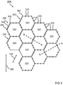
- FIG. 3 shows a schematic representation of a section of the shell portion 215 of the drum of the washing machine FIG. 2
- the casing section 215 has a plurality of curvature segments 320 arranged adjacent to one another.
- the buckling segments 320 are formed in the skirt portion 215.
- each buckling segment 320 has a hexagonal outline.
- the curvature segments 320 are arranged honeycombed adjacent to each other.
- the skirt portion 215 has a plurality of round holes 330.
- the round holes 330 are formed as through holes in the skirt portion 215. In this case, the round holes 330 are arranged along contours or in outline regions of the arching segments 320.
- the skirt portion 215 has a plurality of elongated holes 340.
- the slots 340 are formed as through holes in the shell portion 215.
- Each slot 340 has two end portions 342 and an intermediate portion 344 disposed between the end portions 342.
- the end portions 342 of the slots 340 are rounded.
- a rounding diameter of each end section 342 is greater than or equal to a width dimension of the intermediate section 344 of the slot 340.
- the end sections 342 are bulged in a circular segment.
- the elongated holes 340 represent elongate openings with exemplarily circular start and end.
- the elongated holes 340 are arranged along the outlines or in the outline regions of the arching segments 320. In other words, the elongated holes 340 are disposed in boundary regions between adjacent buckling segments 320. Each buckling segment 320 is bounded by at least one slot 340. The elongated holes 340 extend along side edges of the buckling segments 320.
- each elongated hole 340 is arranged along two opposite side edges, one end section 342 of a further elongated hole 340 is arranged at two opposite corners and two at the four other side edges Round holes 330 arranged.
- a length of a slot 340 within a tolerance range may be equal to an edge length of an edge of a buckling segment 320.
- Each slot 340 has a longitudinal axis 346.
- the slots 340 have mutually parallel longitudinal extension axes 346.
- the longitudinal axis 346 of each elongated hole 340 extends transversely to a side edge of the skirt portion 215.
- the side edge of the skirt portion 215, which is in FIG FIG. 3 is not shown for reasons of space, extends along a direction of rotation 350 and two mutual directions of rotation 350 of the drum in the washing machine.
- FIG. 3 a first section line AA and a second section line BB shown.
- the first cut line AA intersects at least one bulge segment 320 through two opposing round holes 330.
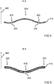
- a sectional view along the first section line AA is shown in FIG. 4 shown.
- the second cutting line BB cuts portions of two adjacent buckling segments 320 across a slot 340.
- a sectional view along the second cutting line BB is shown in FIG FIG. 5 shown.
- the round holes 330 may include a first group of round holes 330 having a first diameter and a second group of round holes 330 having a second diameter.
- the second diameter is larger than the first diameter.
- the second diameter may be greater than 2 millimeters.
- the round holes 330 exemplify circular openings.
- a rounding diameter of each end portion 342 of the elongated holes 340 may correspond to the first diameter or diameter of the round holes 330.
- FIG. 4 shows a sectional view along a section line AA FIG. 3 ,
- the casing section 215 is shown cut through two round holes 330 in the region of a curvature segment 320.
- the round holes 330 are formed in boundary regions 425 in which the bulge segment 320 adjoins adjacent bulge segments.
- the skirt portion 215 is arched in the camber segment 320.
- the skirt portion 215 in the bulge segment 320 is curved relative to the boundary regions 425.
- a radial direction 460 is shown with respect to a rotational axis of the drum by an arrow. It can be seen that the skirt portion 215 in the camber segment 320 is curved radially inwardly along the radial direction 460 toward the axis of rotation of the drum. Furthermore, it can be seen that the boundary regions 425 are arranged radially outwardly relative to the curvature segment 320 relative to the rotational axis of the drum, counter to the radial direction 460.
- FIG. 5 shows a sectional view along a section line BB FIG. 3 ,
- the casing section 215 is cut transversely through a slot 340 in the region of partial sections of two adjacent curvature segments 320.
- the slot 340 is formed in a boundary region 425 between the two adjacent buckling segments 320.
- the skirt portion 215 is curved in the buckling segments 320.
- the skirt portion 215 in the buckling segments 320 is curved relative to the boundary region 425.
- a radial direction 460 with respect to a rotational axis of the drum is shown by an arrow. It can be seen that the skirt portion 215 in the buckling segments 320 is curved radially inwardly along the radial direction 460 toward the axis of rotation of the drum. Furthermore, it can be seen that the boundary region 425 is arranged radially outwardly with respect to the bulge segments 320 relative to the rotational axis of the drum, counter to the radial direction 460.
- the Drum 210 for the washing machine 200 is embodied as a vaulted drum 210 for coarse contamination, wherein the drum 210 may also be referred to as a slotted drum structure drum 210.
- the drum 210 is configured to separate coarse soils and hair from the drum 210 by a specific type and / or shape, as well as the number and arrangement of elongated holes 340 and optionally round holes 330, as well as by additional vaulting with buckling segments 320.
- the shell section 215 or drum shell 215 has elongated holes 340 or elongate openings 340, advantageously on edges of the arching segments 320 or arch structure or arching structure elements.
- the oblong holes 340 thus replace, except for their end portions 342 along the respective edges, round holes 330 which are arranged only at the other edges of the arching segments 320.
Landscapes
- Engineering & Computer Science (AREA)
- Textile Engineering (AREA)
- Main Body Construction Of Washing Machines And Laundry Dryers (AREA)
Abstract
Description
- Die Erfindung betrifft eine Trommel für eine Waschmaschine und eine Waschmaschine.
- Beispielsweise können Waschmaschinen mit sogenannten Schontrommeln für schonende Wäschebehandlung wölbstrukturierte Trommeln mit kreisrunden Öffnungen aufweisen.
- Die
EP 1 118 704 A1 offenbart eine Trommelwaschmaschine, deren Trommel eine Wölbstruktur aufweist. - Der Erfindung stellt sich die Aufgabe, eine verbesserte Trommel für eine Waschmaschine und eine verbesserte Waschmaschine bereitzustellen.
- Erfindungsgemäß wird diese Aufgabe durch eine Trommel für eine Waschmaschine und durch eine Waschmaschine mit den Merkmalen der Hauptansprüche gelöst. Vorteilhafte Ausgestaltungen und Weiterbildungen der Erfindung ergeben sich aus den nachfolgenden Unteransprüchen.
- Die mit der Erfindung erreichbaren Vorteile bestehen neben einem zuverlässigen Entfernen bzw. Separieren größerer Partikel aus der Trommel insbesondere in einem zuverlässigen Entfernen bzw. Separieren länglicher Teile oder Partikel, wie zum Beispiel Haare, aus der Trommel. Durch Ausformen von Schlitzen bzw. ausgeformten Schlitzen in einer Trommelwand kann beispielsweise eine Schmutzentfernung auch für Grobverschmutzungen und Haare optimiert werden. Anders als insbesondere bei einer bekannten Wölbstruktur für gewerbliche Waschmaschinentrommeln kann somit eine Optimierung hinsichtlich Grobverschmutzungen und Haare, wie beispielsweise Menschenhaaren in Friseursalons, Pferdehaaren auf Pferdedecken, etc., erreicht werden. Dabei können Haare einfacher aus der Trommel entfernt werden, da diese dazu neigen, quer zu kreisrunden Öffnungen zu liegen, anstatt längs durchzutreten, jedoch mittels Langlöchern oder Schlitzen zuverlässig aus der Trommel entfernt werden können. Somit kann vermieden werden, dass in der Trommel verbliebene, grobe Verschmutzungen, wie beispielsweise Haare, erneut oder weiterhin an gewaschener Wäsche haften und sich gegebenenfalls zu größeren Büscheln sammeln können, was einem Anwender bei Entnahme der Wäsche negativ auffallen könnte. Somit können eine Reinigungswirkung sowie eine Kundenzufriedenheit auf einfache Weise gesteigert werden.
- Es wird eine Trommel für eine Waschmaschine vorgestellt, wobei die Trommel hohlzylindrisch ausgeformt ist, wobei die Trommel folgende Merkmale aufweist: einen Mantelabschnitt, in dem eine Mehrzahl von Langlöchern als Durchgangslöcher ausgeformt sind.
- Die Waschmaschine kann als eine Maschine zum Waschen oder zum Waschen und Trocknen von Wäsche ausgeführt sein. Beispielsweise kann die Waschmaschine ein Waschautomat, insbesondere ein gewerblicher Waschautomat sein. Die Waschmaschine kann speziell für Anwendungen mit Grobverschmutzungen, wie für Gebäudereiniger, Reiterhöfe, Friseursalons oder dergleichen verwendbar sein. Die Trommel kann ausgebildet sein, um Wäsche während eines Waschvorgangs zu beinhalten. Die Langlöcher können ausgebildet sein, um längliche Partikel und Schmutzteile aus der Trommel austreten zu lassen oder zu entfernen.
- Gemäß einer Ausführungsform kann jedes Langloch abgerundete Endabschnitte aufweisen. Hierbei kann ein Rundungsdurchmesser jedes Endabschnitts größer oder gleich einer Breitenabmessung eines zwischen den Endabschnitten angeordneten Zwischenabschnitts des Langlochs sein. Insbesondere kann das Langloch ein hantelähnliches Schnittprofil aufweisen. Jeder Endabschnitt kann eine Ausbuchtung repräsentieren. Eine solche Ausführungsform bietet den Vorteil, dass eine Kerbwirkung verringert werden kann. Somit kann eine Stabilität eines Materials der Trommel im Bereich der Langlöcher erhöht werden.
- Auch kann sich eine Längserstreckungsachse jedes Langlochs quer zu einer Seitenkante des Mantelabschnitts erstrecken. Hierbei kann zumindest eine Teilmenge der Langlöcher eine gemeinsame Haupterstreckungsrichtung aufweisen. Eine solche Ausführungsform bietet den Vorteil, dass längliche Partikel und Schmutzteile besser entfernt werden können, da ein Bereich, der durch bezüglich einer Drehrichtung der Trommel quer ausgerichtete Langlöcher überstrichen wird, verglichen mit in Drehrichtung ausgerichteten Langlöchern vergrößert sein kann.
- Ferner können in dem Mantelabschnitt eine Mehrzahl von Rundlöchern als Durchgangslöcher ausgeformt sein. Eine solche Ausführungsform bietet den Vorteil, dass eine Schmutzabfuhr aus der Trommel verbessert werden kann, wobei zusätzlich auch eine Schonung der Wäsche weiter gesteigert werden kann.
- Dabei können die Rundlöcher eine erste Gruppe von Rundlöchern mit einem ersten Durchmesser und eine zweite Gruppe von Rundlöchern mit einem zweiten Durchmesser aufweisen. Hierbei kann der zweite Durchmesser größer als der erste Durchmesser sein, wobei der zweite Durchmesser größer als 2 Millimeter sein kann. Alternativ können die Rundlöcher auch einheitlich den zweiten Durchmesser aufweisen. Eine Gruppe von Rundlöchern kann zumindest ein Rundloch umfassen. Eine solche Ausführungsform bietet den Vorteil, dass eine Schmutzabfuhr verbessert werden kann, da größere Öffnungen geeignet sind, um größere Partikel durchtreten zu lassen.
- Zudem können in dem Mantelabschnitt eine Mehrzahl von zueinander benachbart angeordneten Wölbungssegmenten ausgeformt sein. Hierbei kann der Mantelabschnitt in jedem Wölbungssegment radial einwärts zu einer Drehachse der Trommel hin gewölbt sein. Beispielsweise kann der Mantelabschnitt in jedem Wölbungssegment domförmig gewölbt sein. Insbesondere können Wölbungssegmente aneinander angrenzend angeordnet sein. Ein solches Ausführungsbeispiel bietet den Vorteil, dass eine schonende Behandlung der Wäsche verbessert werden kann.
- Dabei können die Langlöcher in Grenzbereichen zwischen benachbarten Wölbungssegmenten angeordnet sein. Hierbei können die Grenzbereiche relativ zu der Drehachse der Trommel radial außerhalb bezüglich der Wölbungssegmente angeordnet sein. Wenn der Mantelabschnitt auch Rundlöcher aufweist, können die Rundlöcher beispielsweise ebenfalls in den Grenzbereichen angeordnet sein. Die Grenzbereiche können somit Muldenabschnitte, Vertiefungsabschnitte oder Täler zwischen den Wölbungssegmenten repräsentieren. Eine solche Ausführungsform bietet den Vorteil, dass eine Schonwirkung der Wäsche sowie eine Schmutzabfuhr verbessert werden können.
- Insbesondere kann jedes Wölbungssegment einen hexagonalen Grundriss aufweisen. Hierbei können die Grenzbereiche einen hexagonalen Verlauf aufweisen. Eine solche Ausführungsform bietet den Vorteil, dass eine Stabilität der Trommel erhöht werden kann.
- Dabei kann bezogen auf ein einzelnes Wölbungssegment entlang zweier gegenüberliegender Seitenkanten des Wölbungssegments jeweils ein Langloch angeordnet sein. Im Bereich der verbleibenden vier Seitenkanten jedes Wölbungssegments können Rundlöcher angeordnet sein. Insbesondere kann eine Länge eines Langlochs innerhalb eines Toleranzbereichs gleich einer Kantenlänge einer Kante des hexagonalen Wölbungssegments sein. Zudem kann das Langloch durch Zwischenstege in zwei oder mehrere Einzelsegmente unterteilt sein. Eine solche Ausführungsform bietet den Vorteil, dass eine Stabilität der Trommel sowie eine Schmutzabfuhr gesteigert werden können.
- Es wird auch eine Waschmaschine vorgestellt, die folgende Merkmale aufweist:
- einen Laugenbehälter; und
- eine Ausführungsform einer vorstehend genannten Trommel, wobei die Trommel in dem Laugenbehälter angeordnet ist.
- In Verbindung mit der Waschmaschine kann eine Ausführungsform der vorstehend genannten Trommel vorteilhaft verwendet oder eingesetzt werden.
- Ein Ausführungsbeispiel der Erfindung ist in den Zeichnungen rein schematisch dargestellt und wird nachfolgend näher beschrieben. Es zeigt
- Figur 1
- eine schematische Darstellung eines Ausschnitts aus einem Mantelabschnitt einer Waschmaschinentrommel;
- Figur 2
- eine schematische Darstellung einer Waschmaschine gemäß einem Ausführungsbeispiel der vorliegenden Erfindung;
- Figur 3
- eine schematische Darstellung eines Ausschnitts aus einem Mantelabschnitt einer Trommel der Waschmaschine aus
Figur 2 ; - Figur 4
- eine Schnittdarstellung entlang einer Schnittlinie A-A aus
Figur 3 ; und - Figur 5
- eine Schnittdarstellung entlang einer Schnittlinie B-B aus
Figur 3 . -
Figur 1 zeigt eine schematische Darstellung eines Ausschnitts aus einem Mantelabschnitt 100 einer Waschmaschinentrommel. In dem Mantelabschnitt 100 sind eine Mehrzahl von Rundlöchern 110 ausgeformt. Beispielhaft sind die Rundlöcher 110 entlang Umrisslinien aneinandergefügter Sechsecke angeordnet. Hierbei ergibt sich beispielhaft durch eine Anordnung der Rundlöcher 110 ein wabenförmiges Muster. -
Figur 2 zeigt eine schematische Darstellung einer Waschmaschine 200 gemäß einem Ausführungsbeispiel der vorliegenden Erfindung. Die Waschmaschine 200 weist eine Türe 202 auf, mittels derer ein Laugenbehälter 204 der Waschmaschine 200 verschließbar ist. In dem Laugenbehälter 204 der Waschmaschine 200 ist eine Trommel 210 angeordnet. Die Trommel 110 ist in dem Laugenbehälter 204 bzw. dem Innenraum der Waschmaschine 200 drehbar gelagert angeordnet. Dabei ist die Trommel 210 hohlzylindrisch ausgeformt. Die Trommel 210 weist einen Mantelabschnitt 215 auf. Auf den Mantelabschnitt 215 wird nachfolgend detaillierter eingegangen. -
Figur 3 zeigt eine schematische Darstellung eines Ausschnitts aus dem Mantelabschnitt 215 der Trommel der Waschmaschine ausFigur 2 . Der Mantelabschnitt 215 weist eine Mehrzahl von zueinander benachbart angeordneten Wölbungssegmenten 320 auf. Die Wölbungssegmente 320 sind in dem Mantelabschnitt 215 ausgeformt. Gemäß dem inFigur 3 dargestellten Ausführungsbeispiel der vorliegenden Erfindung weist jedes Wölbungssegment 320 einen hexagonalen Grundriss auf. Dabei sind die Wölbungssegmente 320 wabenartig aneinander angrenzend angeordnet. Auch weist der Mantelabschnitt 215 eine Mehrzahl von Rundlöchern 330 auf. Die Rundlöcher 330 sind als Durchgangslöcher in dem Mantelabschnitt 215 ausgeformt. Dabei sind die Rundlöcher 330 entlang von Umrissen oder in Umrissbereichen der Wölbungssegmente 320 angeordnet. - Der Mantelabschnitt 215 weist eine Mehrzahl von Langlöchern 340 auf. Dabei sind die Langlöcher 340 als Durchgangslöcher in dem Mantelabschnitt 215 ausgeformt. Jedes Langloch 340 weist zwei Endabschnitte 342 und einen Zwischenabschnitt 344 auf, der zwischen den Endabschnitten 342 angeordnet ist. Gemäß dem in
Figur 3 dargestellten Ausführungsbeispiel der vorliegenden Erfindung sind die Endabschnitte 342 der Langlöcher 340 abgerundet. Dabei ist ein Rundungsdurchmesser jedes Endabschnitts 342 größer oder gleich einer Breitenabmessung des Zwischenabschnitts 344 des Langlochs 340. insbesondere sind die Endabschnitte 342 kreissegmentförmig ausgebuchtet. Anders ausgedrückt repräsentieren die Langlöcher 340 längliche Öffnungen mit beispielhaft kreisrundem Anfang und Ende. - Die Langlöcher 340 sind entlang der Umrisse bzw. in den Umrissbereichen der Wölbungssegmente 320 angeordnet. Anders ausgedrückt sind die Langlöcher 340 in Grenzbereichen zwischen benachbarten Wölbungssegmenten 320 angeordnet. Jedes Wölbungssegment 320 ist durch zumindest ein Langloch 340 begrenzt. Die Langlöcher 340 erstrecken sich entlang Seitenkanten der Wölbungssegmente 320.
- Hinsichtlich jedes Wölbungssegmentes 320, das an allen sechs Seitenkanten an benachbarte Wölbungssegmente 320 grenzt, ist entlang zweier gegenüberliegender Seitenkanten jeweils ein Langloch 340 angeordnet, ist an zwei gegenüberliegenden Ecken jeweils ein Endabschnitt 342 eines weiteren Langloches 340 angeordnet und sind an den vier weiteren Seitenkanten jeweils zwei Rundlöcher 330 angeordnet.
- Insbesondere kann eine Länge eines Langlochs 340 innerhalb eines Toleranzbereichs gleich einer Kantenlänge einer Kante eines Wölbungssegments 320 sein. Jedes Langloch 340 weist eine Längserstreckungsachse 346 auf. Gemäß dem in
Figur 3 dargestellten Ausführungsbeispiel der vorliegenden Erfindung weisen die Langlöcher 340 zueinander parallele Längserstreckungsachsen 346 auf. Auch erstreckt sich die Längserstreckungsachse 346 jedes Langlochs 340 quer zu einer Seitenkante des Mantelabschnitts 215. Die Seitenkante des Mantelabschnitts 215, die inFigur 3 aus Platzgründen nicht dargestellt ist, erstreckt sich entlang einer Drehrichtung 350 bzw. zweier gegenseitiger Drehrichtungen 350 der Trommel in der Waschmaschine. - Ferner sind in
Figur 3 eine erste Schnittlinie A-A und eine zweite Schnittlinie B-B dargestellt. Die erste Schnittlinie A-A schneidet zumindest ein Wölbungssegment 320 durch zwei gegenüberliegende Rundlöcher 330 hindurch. Eine Schnittdarstellung entlang der ersten Schnittlinie A-A ist inFigur 4 gezeigt. Die zweite Schnittlinie B-B schneidet Teilabschnitte von zwei benachbarten Wölbungssegmenten 320 quer durch ein Langloch 340. Eine Schnittdarstellung entlang der zweiten Schnittlinie B-B ist inFigur 5 gezeigt. - Gemäß einem Ausführungsbeispiel können die Rundlöcher 330 eine erste Gruppe von Rundlöchern 330 mit einem ersten Durchmesser und eine zweite Gruppe von Rundlöchern 330 mit einem zweiten Durchmesser aufweisen. Der zweite Durchmesser ist hierbei größer als der erste Durchmesser. Beispielsweise kann der zweite Durchmesser größer als 2 Millimeter sein. Die Rundlöcher 330 repräsentieren beispielhaft kreisrunde Öffnungen. Insbesondere kann ein Rundungsdurchmesser jedes Endabschnittes 342 der Langlöcher 340 dem ersten Durchmesser oder dem zweiten Durchmesser der Rundlöcher 330 entsprechen.
-
Figur 4 zeigt eine Schnittdarstellung entlang einer Schnittlinie A-A ausFigur 3 . Hierbei ist der Mantelabschnitt 215 im Bereich eines Wölbungssegmentes 320 durch zwei Rundlöcher 330 hindurch geschnitten dargestellt. Die Rundlöcher 330 sind in Grenzbereichen 425 ausgeformt, in denen das Wölbungssegment 320 an benachbarte Wölbungssegmente angrenzt. Der Mantelabschnitt 215 ist in dem Wölbungssegment 320 gewölbt. Insbesondere ist der Mantelabschnitt 215 in dem Wölbungssegment 320 relativ zu den Grenzbereichen 425 gewölbt. - In
Figur 4 ist ferner eine radiale Richtung 460 in Bezug zu einer Drehachse der Trommel durch einen Pfeil dargestellt. Es ist erkennbar, dass der Mantelabschnitt 215 in dem Wölbungssegment 320 radial einwärts entlang der radialen Richtung 460 zu der Drehachse der Trommel hin gewölbt ist. Ferner ist erkennbar, dass die Grenzbereiche 425 relativ zu der Drehachse der Trommel entgegen der radialen Richtung 460 radial auswärts bezüglich des Wölbungssegmentes 320 angeordnet sind. -
Figur 5 zeigt eine Schnittdarstellung entlang einer Schnittlinie B-B ausFigur 3 . Dabei ist der Mantelabschnitt 215 im Bereich von Teilabschnitten zweier benachbarter Wölbungssegmente 320 quer durch ein Langloch 340 geschnitten. Das Langloch 340 ist in einem Grenzbereich 425 zwischen den zwei benachbarten Wölbungssegmenten 320 ausgeformt. Der Mantelabschnitt 215 ist in den Wölbungssegmenten 320 gewölbt. Insbesondere ist der Mantelabschnitt 215 in den Wölbungssegmenten 320 relativ zu dem Grenzbereich 425 gewölbt. - In
Figur 5 ist eine radiale Richtung 460 in Bezug zu einer Drehachse der Trommel durch einen Pfeil dargestellt. Es ist erkennbar, dass der Mantelabschnitt 215 in den Wölbungssegmenten 320 radial einwärts entlang der radialen Richtung 460 zu der Drehachse der Trommel hin gewölbt ist. Ferner ist erkennbar, dass der Grenzbereich 425 relativ zu der Drehachse der Trommel entgegen der radialen Richtung 460 radial auswärts bezüglich der Wölbungssegmente 320 angeordnet ist. - Unter Bezugnahme auf die
Figuren 2 bis 5 wird ein Ausführungsbeispiel der vorliegenden Erfindung nachfolgend nochmals zusammenfassend und mit anderen Worten erläutert. Die Trommel 210 für die Waschmaschine 200 ist als eine wölbstrukturierte Trommel 210 für Grobverschmutzungen ausgeführt, wobei die Trommel 210 auch als eine geschlitzte Wölbstrukturtrommel 210 bezeichnet werden kann. Die Trommel 210 ist ausgebildet, um Grobverschmutzungen und Haare durch eine speziell ausgeführte Art und/oder Form sowie Anzahl und Anordnung von Langlöchern 340 und optional Rundlöchern 330 sowie durch zusätzliche Wölbstrukturierung mit Wölbungssegmenten 320 aus der Trommel 210 zu separieren. Der Mantelabschnitt 215 oder Trommelmantel 215 weist Langlöcher 340 oder längliche Öffnungen 340 auf, vorteilhafterweise an Kanten der Wölbungssegmente 320 bzw. Wölbstruktur oder Wölbstrukturelemente. Die Langlöcher 340 ersetzen bis auf ihre Endabschnitte 342 entlang der jeweiligen Kanten somit Rundlöcher 330, die lediglich an den anderen Kanten der Wölbungssegmente 320 angeordnet sind.
Claims (10)
- Trommel (210) für eine Waschmaschine (200), wobei die Trommel (210) hohlzylindrisch ausgeformt ist, wobei die Trommel (210) folgende Merkmale aufweist:einen Mantelabschnitt (215), in dem eine Mehrzahl von Langlöchern (340) als Durchgangslöcher ausgeformt sind.
- Trommel (210) gemäß Anspruch 1, bei der jedes Langloch (340) abgerundete Endabschnitte (342) aufweist, wobei ein Rundungsdurchmesser jedes Endabschnitts (342) größer oder gleich einer Breitenabmessung eines zwischen den Endabschnitten (342) angeordneten Zwischenabschnitts (344) des Langlochs (340) ist.
- Trommel (210) gemäß einem der vorangegangenen Ansprüche, bei der sich eine Längserstreckungsachse (346) jedes Langlochs (340) quer zu einer Seitenkante des Mantelabschnitts (215) erstreckt.
- Trommel (210) gemäß einem der vorangegangenen Ansprüche, bei der in dem Mantelabschnitt (215) eine Mehrzahl von Rundlöchern (330) als Durchgangslöcher ausgeformt sind.
- Trommel (210) gemäß Anspruch 4, bei der die Rundlöcher (330) eine erste Gruppe von Rundlöchern (330) mit einem ersten Durchmesser und eine zweite Gruppe von Rundlöchern (330) mit einem zweiten Durchmesser aufweisen, wobei der zweite Durchmesser größer als der erste Durchmesser ist, wobei der zweite Durchmesser größer als 2 Millimeter ist.
- Trommel (210) gemäß einem der vorangegangenen Ansprüche, bei der in dem Mantelabschnitt (215) eine Mehrzahl von zueinander benachbart angeordneten Wölbungssegmenten (320) ausgeformt sind, wobei der Mantelabschnitt (215) in jedem Wölbungssegment (320) radial einwärts zu einer Drehachse der Trommel (210) hin gewölbt ist.
- Trommel (210) gemäß Anspruch 6, bei der die Langlöcher (340) in Grenzbereichen (425) zwischen benachbarten Wölbungssegmenten (320) angeordnet sind.
- Trommel (210) gemäß einem der Ansprüche 6 bis 7, bei der jedes Wölbungssegment (320) einen hexagonalen Grundriss aufweist.
- Trommel (210) gemäß Anspruch 8, bei der bezogen auf ein einzelnes Wölbungssegment (320) entlang zweier gegenüberliegender Seitenkanten des Wölbungssegments (320) jeweils ein Langloch (340) angeordnet ist.
- Waschmaschine (200), die folgende Merkmale aufweist:einen Laugenbehälter (204); undeine Trommel (210) gemäß einem der vorangegangenen Ansprüche, wobei die Trommel (210) in dem Laugenbehälter (204) angeordnet ist.
Priority Applications (1)
| Application Number | Priority Date | Filing Date | Title |
|---|---|---|---|
| PL16020120T PL3091112T3 (pl) | 2015-05-04 | 2016-04-08 | Pralka i bęben dla pralki |
Applications Claiming Priority (1)
| Application Number | Priority Date | Filing Date | Title |
|---|---|---|---|
| DE102015106862.1A DE102015106862A1 (de) | 2015-05-04 | 2015-05-04 | Waschmaschine und Trommel für eine Waschmaschine |
Publications (2)
| Publication Number | Publication Date |
|---|---|
| EP3091112A1 true EP3091112A1 (de) | 2016-11-09 |
| EP3091112B1 EP3091112B1 (de) | 2020-03-04 |
Family
ID=55701668
Family Applications (1)
| Application Number | Title | Priority Date | Filing Date |
|---|---|---|---|
| EP16020120.8A Active EP3091112B1 (de) | 2015-05-04 | 2016-04-08 | Waschmaschine und trommel für eine waschmaschine |
Country Status (4)
| Country | Link |
|---|---|
| EP (1) | EP3091112B1 (de) |
| DE (1) | DE102015106862A1 (de) |
| ES (1) | ES2782798T3 (de) |
| PL (1) | PL3091112T3 (de) |
Citations (6)
| Publication number | Priority date | Publication date | Assignee | Title |
|---|---|---|---|---|
| DE6606902U (de) * | 1967-08-09 | 1970-12-17 | Siemens Elektrogeraete Gmbh | Waeschetrommel mit gelochtem mantel fuer zum schleudern bestimmte waeschebebandlunsmaschinen |
| JPS6420898A (en) * | 1987-07-15 | 1989-01-24 | Mitsubishi Electric Corp | Drum type washing machine |
| EP1118704A1 (de) | 1996-11-02 | 2001-07-25 | Miele & Cie. GmbH & Co. | Trommelwaschmaschine |
| JP2006068192A (ja) * | 2004-09-01 | 2006-03-16 | Matsushita Electric Ind Co Ltd | 洗濯機 |
| EP2474659A1 (de) * | 2011-01-11 | 2012-07-11 | Miele & Cie. KG | Trommel mit Wölbstruktur für eine Waschmaschine |
| CN102912587A (zh) * | 2012-11-02 | 2013-02-06 | 张宇琪 | 一种手动式洗衣滚桶 |
-
2015
- 2015-05-04 DE DE102015106862.1A patent/DE102015106862A1/de not_active Withdrawn
-
2016
- 2016-04-08 EP EP16020120.8A patent/EP3091112B1/de active Active
- 2016-04-08 PL PL16020120T patent/PL3091112T3/pl unknown
- 2016-04-08 ES ES16020120T patent/ES2782798T3/es active Active
Patent Citations (6)
| Publication number | Priority date | Publication date | Assignee | Title |
|---|---|---|---|---|
| DE6606902U (de) * | 1967-08-09 | 1970-12-17 | Siemens Elektrogeraete Gmbh | Waeschetrommel mit gelochtem mantel fuer zum schleudern bestimmte waeschebebandlunsmaschinen |
| JPS6420898A (en) * | 1987-07-15 | 1989-01-24 | Mitsubishi Electric Corp | Drum type washing machine |
| EP1118704A1 (de) | 1996-11-02 | 2001-07-25 | Miele & Cie. GmbH & Co. | Trommelwaschmaschine |
| JP2006068192A (ja) * | 2004-09-01 | 2006-03-16 | Matsushita Electric Ind Co Ltd | 洗濯機 |
| EP2474659A1 (de) * | 2011-01-11 | 2012-07-11 | Miele & Cie. KG | Trommel mit Wölbstruktur für eine Waschmaschine |
| CN102912587A (zh) * | 2012-11-02 | 2013-02-06 | 张宇琪 | 一种手动式洗衣滚桶 |
Also Published As
| Publication number | Publication date |
|---|---|
| DE102015106862A1 (de) | 2016-11-10 |
| PL3091112T3 (pl) | 2020-06-15 |
| ES2782798T3 (es) | 2020-09-16 |
| EP3091112B1 (de) | 2020-03-04 |
Similar Documents
| Publication | Publication Date | Title |
|---|---|---|
| EP1820892B1 (de) | Trommelschale zur Erzeugung von Strukturen und/oder Reliefmustern auf der Oberfläche eines gewebten oder nicht gewebten Zellenmaterials oder Vlieses | |
| EP2508658B1 (de) | Sägezahngarnitur | |
| DE2628310C3 (de) | Auswechselbare Klinge für die umlaufende Nabe von Luftreifenschäl-, -raspel- oder -Schlichtmaschinen | |
| DE3210503A1 (de) | Vorrichtung zur aufloesung und sortierung vom faserigen stoff | |
| DE19905534B4 (de) | Trommelwaschmaschine mit einer Wäschetrommel, deren Trommelmantel eine strukturierte Oberfläche aufweist | |
| DE102020201730A1 (de) | Fahrzeugluftreifen | |
| EP3043962B1 (de) | Schneidwerkzeug | |
| EP2177657B1 (de) | Trommel für eine Waschmaschine | |
| EP3091112B1 (de) | Waschmaschine und trommel für eine waschmaschine | |
| DE102015108230A1 (de) | Klingenelement für einen Refiner | |
| EP2253242A1 (de) | Bürstenscheibe für eine Bodenreinigungsmaschine | |
| EP0547253A1 (de) | Strömungsgleichrichter für einen Ventilator | |
| EP4475802B1 (de) | Pelotte zur aufnahme einer bandage und bandage | |
| EP3473754B1 (de) | Garniturdraht | |
| EP2474659A1 (de) | Trommel mit Wölbstruktur für eine Waschmaschine | |
| EP3784831A1 (de) | Stoffauflöser | |
| EP2758582B1 (de) | Wäschetrommel mit trommelprofil für optimierte schleuderwirkung | |
| DE19941073A1 (de) | Verfahren und Vorrichtung zum Naßbehandeln, insbesondere Waschen, von Wäschestücken | |
| EP2920352B1 (de) | Filteranordnung für eine wäschebehandlungsmaschine | |
| WO2016193853A1 (de) | Ganzstahlgarnitur | |
| EP0468226B1 (de) | Aufschliessvorrichtung für einen Mischer od. dgl. | |
| EP1081266B1 (de) | Verfahren und Vorrichtung zum Nassbehandeln, insbesondere Waschen, von Wäschestücken | |
| DE202004021110U1 (de) | Matratze mit einem Distanzgewebe | |
| DE2055244A1 (de) | Heu Konditionierungswalze | |
| EP1939341A1 (de) | Prägewalze zur Herstellung von Vlies |
Legal Events
| Date | Code | Title | Description |
|---|---|---|---|
| PUAI | Public reference made under article 153(3) epc to a published international application that has entered the european phase |
Free format text: ORIGINAL CODE: 0009012 |
|
| AK | Designated contracting states |
Kind code of ref document: A1 Designated state(s): AL AT BE BG CH CY CZ DE DK EE ES FI FR GB GR HR HU IE IS IT LI LT LU LV MC MK MT NL NO PL PT RO RS SE SI SK SM TR |
|
| AX | Request for extension of the european patent |
Extension state: BA ME |
|
| STAA | Information on the status of an ep patent application or granted ep patent |
Free format text: STATUS: REQUEST FOR EXAMINATION WAS MADE |
|
| 17P | Request for examination filed |
Effective date: 20170509 |
|
| RBV | Designated contracting states (corrected) |
Designated state(s): AL AT BE BG CH CY CZ DE DK EE ES FI FR GB GR HR HU IE IS IT LI LT LU LV MC MK MT NL NO PL PT RO RS SE SI SK SM TR |
|
| STAA | Information on the status of an ep patent application or granted ep patent |
Free format text: STATUS: EXAMINATION IS IN PROGRESS |
|
| 17Q | First examination report despatched |
Effective date: 20180709 |
|
| GRAP | Despatch of communication of intention to grant a patent |
Free format text: ORIGINAL CODE: EPIDOSNIGR1 |
|
| STAA | Information on the status of an ep patent application or granted ep patent |
Free format text: STATUS: GRANT OF PATENT IS INTENDED |
|
| INTG | Intention to grant announced |
Effective date: 20191031 |
|
| GRAS | Grant fee paid |
Free format text: ORIGINAL CODE: EPIDOSNIGR3 |
|
| GRAA | (expected) grant |
Free format text: ORIGINAL CODE: 0009210 |
|
| STAA | Information on the status of an ep patent application or granted ep patent |
Free format text: STATUS: THE PATENT HAS BEEN GRANTED |
|
| AK | Designated contracting states |
Kind code of ref document: B1 Designated state(s): AL AT BE BG CH CY CZ DE DK EE ES FI FR GB GR HR HU IE IS IT LI LT LU LV MC MK MT NL NO PL PT RO RS SE SI SK SM TR |
|
| REG | Reference to a national code |
Ref country code: GB Ref legal event code: FG4D Free format text: NOT ENGLISH |
|
| REG | Reference to a national code |
Ref country code: CH Ref legal event code: EP |
|
| REG | Reference to a national code |
Ref country code: AT Ref legal event code: REF Ref document number: 1240467 Country of ref document: AT Kind code of ref document: T Effective date: 20200315 |
|
| REG | Reference to a national code |
Ref country code: DE Ref legal event code: R096 Ref document number: 502016008977 Country of ref document: DE |
|
| REG | Reference to a national code |
Ref country code: IE Ref legal event code: FG4D Free format text: LANGUAGE OF EP DOCUMENT: GERMAN |
|
| REG | Reference to a national code |
Ref country code: RO Ref legal event code: EPE |
|
| REG | Reference to a national code |
Ref country code: NL Ref legal event code: FP |
|
| PG25 | Lapsed in a contracting state [announced via postgrant information from national office to epo] |
Ref country code: RS Free format text: LAPSE BECAUSE OF FAILURE TO SUBMIT A TRANSLATION OF THE DESCRIPTION OR TO PAY THE FEE WITHIN THE PRESCRIBED TIME-LIMIT Effective date: 20200304 Ref country code: FI Free format text: LAPSE BECAUSE OF FAILURE TO SUBMIT A TRANSLATION OF THE DESCRIPTION OR TO PAY THE FEE WITHIN THE PRESCRIBED TIME-LIMIT Effective date: 20200304 Ref country code: NO Free format text: LAPSE BECAUSE OF FAILURE TO SUBMIT A TRANSLATION OF THE DESCRIPTION OR TO PAY THE FEE WITHIN THE PRESCRIBED TIME-LIMIT Effective date: 20200604 |
|
| PG25 | Lapsed in a contracting state [announced via postgrant information from national office to epo] |
Ref country code: GR Free format text: LAPSE BECAUSE OF FAILURE TO SUBMIT A TRANSLATION OF THE DESCRIPTION OR TO PAY THE FEE WITHIN THE PRESCRIBED TIME-LIMIT Effective date: 20200605 Ref country code: LV Free format text: LAPSE BECAUSE OF FAILURE TO SUBMIT A TRANSLATION OF THE DESCRIPTION OR TO PAY THE FEE WITHIN THE PRESCRIBED TIME-LIMIT Effective date: 20200304 Ref country code: SE Free format text: LAPSE BECAUSE OF FAILURE TO SUBMIT A TRANSLATION OF THE DESCRIPTION OR TO PAY THE FEE WITHIN THE PRESCRIBED TIME-LIMIT Effective date: 20200304 Ref country code: HR Free format text: LAPSE BECAUSE OF FAILURE TO SUBMIT A TRANSLATION OF THE DESCRIPTION OR TO PAY THE FEE WITHIN THE PRESCRIBED TIME-LIMIT Effective date: 20200304 Ref country code: BG Free format text: LAPSE BECAUSE OF FAILURE TO SUBMIT A TRANSLATION OF THE DESCRIPTION OR TO PAY THE FEE WITHIN THE PRESCRIBED TIME-LIMIT Effective date: 20200604 |
|
| REG | Reference to a national code |
Ref country code: LT Ref legal event code: MG4D |
|
| REG | Reference to a national code |
Ref country code: ES Ref legal event code: FG2A Ref document number: 2782798 Country of ref document: ES Kind code of ref document: T3 Effective date: 20200916 |
|
| PG25 | Lapsed in a contracting state [announced via postgrant information from national office to epo] |
Ref country code: LT Free format text: LAPSE BECAUSE OF FAILURE TO SUBMIT A TRANSLATION OF THE DESCRIPTION OR TO PAY THE FEE WITHIN THE PRESCRIBED TIME-LIMIT Effective date: 20200304 Ref country code: EE Free format text: LAPSE BECAUSE OF FAILURE TO SUBMIT A TRANSLATION OF THE DESCRIPTION OR TO PAY THE FEE WITHIN THE PRESCRIBED TIME-LIMIT Effective date: 20200304 Ref country code: SM Free format text: LAPSE BECAUSE OF FAILURE TO SUBMIT A TRANSLATION OF THE DESCRIPTION OR TO PAY THE FEE WITHIN THE PRESCRIBED TIME-LIMIT Effective date: 20200304 Ref country code: PT Free format text: LAPSE BECAUSE OF FAILURE TO SUBMIT A TRANSLATION OF THE DESCRIPTION OR TO PAY THE FEE WITHIN THE PRESCRIBED TIME-LIMIT Effective date: 20200729 Ref country code: SK Free format text: LAPSE BECAUSE OF FAILURE TO SUBMIT A TRANSLATION OF THE DESCRIPTION OR TO PAY THE FEE WITHIN THE PRESCRIBED TIME-LIMIT Effective date: 20200304 Ref country code: CZ Free format text: LAPSE BECAUSE OF FAILURE TO SUBMIT A TRANSLATION OF THE DESCRIPTION OR TO PAY THE FEE WITHIN THE PRESCRIBED TIME-LIMIT Effective date: 20200304 Ref country code: IS Free format text: LAPSE BECAUSE OF FAILURE TO SUBMIT A TRANSLATION OF THE DESCRIPTION OR TO PAY THE FEE WITHIN THE PRESCRIBED TIME-LIMIT Effective date: 20200704 |
|
| REG | Reference to a national code |
Ref country code: CH Ref legal event code: PL |
|
| REG | Reference to a national code |
Ref country code: DE Ref legal event code: R097 Ref document number: 502016008977 Country of ref document: DE |
|
| PG25 | Lapsed in a contracting state [announced via postgrant information from national office to epo] |
Ref country code: MC Free format text: LAPSE BECAUSE OF FAILURE TO SUBMIT A TRANSLATION OF THE DESCRIPTION OR TO PAY THE FEE WITHIN THE PRESCRIBED TIME-LIMIT Effective date: 20200304 |
|
| PLBE | No opposition filed within time limit |
Free format text: ORIGINAL CODE: 0009261 |
|
| STAA | Information on the status of an ep patent application or granted ep patent |
Free format text: STATUS: NO OPPOSITION FILED WITHIN TIME LIMIT |
|
| PG25 | Lapsed in a contracting state [announced via postgrant information from national office to epo] |
Ref country code: LU Free format text: LAPSE BECAUSE OF NON-PAYMENT OF DUE FEES Effective date: 20200408 Ref country code: LI Free format text: LAPSE BECAUSE OF NON-PAYMENT OF DUE FEES Effective date: 20200430 Ref country code: DK Free format text: LAPSE BECAUSE OF FAILURE TO SUBMIT A TRANSLATION OF THE DESCRIPTION OR TO PAY THE FEE WITHIN THE PRESCRIBED TIME-LIMIT Effective date: 20200304 Ref country code: CH Free format text: LAPSE BECAUSE OF NON-PAYMENT OF DUE FEES Effective date: 20200430 |
|
| REG | Reference to a national code |
Ref country code: BE Ref legal event code: MM Effective date: 20200430 |
|
| 26N | No opposition filed |
Effective date: 20201207 |
|
| PG25 | Lapsed in a contracting state [announced via postgrant information from national office to epo] |
Ref country code: SI Free format text: LAPSE BECAUSE OF FAILURE TO SUBMIT A TRANSLATION OF THE DESCRIPTION OR TO PAY THE FEE WITHIN THE PRESCRIBED TIME-LIMIT Effective date: 20200304 Ref country code: BE Free format text: LAPSE BECAUSE OF NON-PAYMENT OF DUE FEES Effective date: 20200430 |
|
| PG25 | Lapsed in a contracting state [announced via postgrant information from national office to epo] |
Ref country code: IE Free format text: LAPSE BECAUSE OF NON-PAYMENT OF DUE FEES Effective date: 20200408 |
|
| PG25 | Lapsed in a contracting state [announced via postgrant information from national office to epo] |
Ref country code: MT Free format text: LAPSE BECAUSE OF FAILURE TO SUBMIT A TRANSLATION OF THE DESCRIPTION OR TO PAY THE FEE WITHIN THE PRESCRIBED TIME-LIMIT Effective date: 20200304 Ref country code: CY Free format text: LAPSE BECAUSE OF FAILURE TO SUBMIT A TRANSLATION OF THE DESCRIPTION OR TO PAY THE FEE WITHIN THE PRESCRIBED TIME-LIMIT Effective date: 20200304 |
|
| REG | Reference to a national code |
Ref country code: AT Ref legal event code: MM01 Ref document number: 1240467 Country of ref document: AT Kind code of ref document: T Effective date: 20210408 |
|
| PG25 | Lapsed in a contracting state [announced via postgrant information from national office to epo] |
Ref country code: MK Free format text: LAPSE BECAUSE OF FAILURE TO SUBMIT A TRANSLATION OF THE DESCRIPTION OR TO PAY THE FEE WITHIN THE PRESCRIBED TIME-LIMIT Effective date: 20200304 Ref country code: AL Free format text: LAPSE BECAUSE OF FAILURE TO SUBMIT A TRANSLATION OF THE DESCRIPTION OR TO PAY THE FEE WITHIN THE PRESCRIBED TIME-LIMIT Effective date: 20200304 |
|
| PG25 | Lapsed in a contracting state [announced via postgrant information from national office to epo] |
Ref country code: AT Free format text: LAPSE BECAUSE OF NON-PAYMENT OF DUE FEES Effective date: 20210408 |
|
| P01 | Opt-out of the competence of the unified patent court (upc) registered |
Effective date: 20230528 |
|
| REG | Reference to a national code |
Ref country code: DE Ref legal event code: R084 Ref document number: 502016008977 Country of ref document: DE |
|
| PGFP | Annual fee paid to national office [announced via postgrant information from national office to epo] |
Ref country code: NL Payment date: 20250424 Year of fee payment: 10 |
|
| PGFP | Annual fee paid to national office [announced via postgrant information from national office to epo] |
Ref country code: DE Payment date: 20250430 Year of fee payment: 10 |
|
| PGFP | Annual fee paid to national office [announced via postgrant information from national office to epo] |
Ref country code: ES Payment date: 20250513 Year of fee payment: 10 |
|
| PGFP | Annual fee paid to national office [announced via postgrant information from national office to epo] |
Ref country code: IT Payment date: 20250422 Year of fee payment: 10 |
|
| PGFP | Annual fee paid to national office [announced via postgrant information from national office to epo] |
Ref country code: FR Payment date: 20250424 Year of fee payment: 10 |
|
| PGFP | Annual fee paid to national office [announced via postgrant information from national office to epo] |
Ref country code: GB Payment date: 20260313 Year of fee payment: 11 |
|
| PGFP | Annual fee paid to national office [announced via postgrant information from national office to epo] |
Ref country code: RO Payment date: 20260331 Year of fee payment: 11 |
|
| PGFP | Annual fee paid to national office [announced via postgrant information from national office to epo] |
Ref country code: TR Payment date: 20260327 Year of fee payment: 11 |
|
| PGFP | Annual fee paid to national office [announced via postgrant information from national office to epo] |
Ref country code: PL Payment date: 20260313 Year of fee payment: 11 |