EP3085997A1 - Luftleithaube für ein getriebe und getriebe mit einer luftleithaube - Google Patents
Luftleithaube für ein getriebe und getriebe mit einer luftleithaube Download PDFInfo
- Publication number
- EP3085997A1 EP3085997A1 EP15164779.9A EP15164779A EP3085997A1 EP 3085997 A1 EP3085997 A1 EP 3085997A1 EP 15164779 A EP15164779 A EP 15164779A EP 3085997 A1 EP3085997 A1 EP 3085997A1
- Authority
- EP
- European Patent Office
- Prior art keywords
- transmission
- radial fan
- drive shaft
- air guide
- housing
- Prior art date
- Legal status (The legal status is an assumption and is not a legal conclusion. Google has not performed a legal analysis and makes no representation as to the accuracy of the status listed.)
- Granted
Links
Images


Classifications
-
- F—MECHANICAL ENGINEERING; LIGHTING; HEATING; WEAPONS; BLASTING
- F16—ENGINEERING ELEMENTS AND UNITS; GENERAL MEASURES FOR PRODUCING AND MAINTAINING EFFECTIVE FUNCTIONING OF MACHINES OR INSTALLATIONS; THERMAL INSULATION IN GENERAL
- F16H—GEARING
- F16H57/00—General details of gearing
- F16H57/04—Features relating to lubrication or cooling or heating
- F16H57/0412—Cooling or heating; Control of temperature
- F16H57/0415—Air cooling or ventilation; Heat exchangers; Thermal insulations
- F16H57/0416—Air cooling or ventilation
-
- F—MECHANICAL ENGINEERING; LIGHTING; HEATING; WEAPONS; BLASTING
- F16—ENGINEERING ELEMENTS AND UNITS; GENERAL MEASURES FOR PRODUCING AND MAINTAINING EFFECTIVE FUNCTIONING OF MACHINES OR INSTALLATIONS; THERMAL INSULATION IN GENERAL
- F16H—GEARING
- F16H57/00—General details of gearing
- F16H57/02—Gearboxes; Mounting gearing therein
- F16H57/027—Gearboxes; Mounting gearing therein characterised by means for venting gearboxes, e.g. air breathers
-
- F—MECHANICAL ENGINEERING; LIGHTING; HEATING; WEAPONS; BLASTING
- F16—ENGINEERING ELEMENTS AND UNITS; GENERAL MEASURES FOR PRODUCING AND MAINTAINING EFFECTIVE FUNCTIONING OF MACHINES OR INSTALLATIONS; THERMAL INSULATION IN GENERAL
- F16H—GEARING
- F16H57/00—General details of gearing
- F16H57/02—Gearboxes; Mounting gearing therein
- F16H57/031—Gearboxes; Mounting gearing therein characterised by covers or lids for gearboxes
-
- F—MECHANICAL ENGINEERING; LIGHTING; HEATING; WEAPONS; BLASTING
- F16—ENGINEERING ELEMENTS AND UNITS; GENERAL MEASURES FOR PRODUCING AND MAINTAINING EFFECTIVE FUNCTIONING OF MACHINES OR INSTALLATIONS; THERMAL INSULATION IN GENERAL
- F16H—GEARING
- F16H57/00—General details of gearing
- F16H57/02—Gearboxes; Mounting gearing therein
- F16H2057/02039—Gearboxes for particular applications
- F16H2057/02069—Gearboxes for particular applications for industrial applications
Definitions
- the invention relates to a Gutleithaube for a transmission, in particular a Heilleithaube for a radial fan for cooling a transmission, and a transmission with a Heilleithaube.
- Gear units become very warm due to the power loss during operation.
- An oil temperature in the gearbox limits the permissible mechanical power of the respective gearbox.
- External oil cooling systems are often undesirable, so that cooling must be done by the air surrounding the transmission (ambient air).
- the DE 198 44 04 U describes a fan that is used in conjunction with an air duct for surface cooling of a transmission.
- the fan is surrounded by the air duct.
- the air duct deflects the airflow generated by the fan on the immediately adjacent to the fan gearbox.
- the DE 10 2012 013 351 A1 describes a radial fan with two shields.
- the radial fan is enclosed by a Heilleithaube, which by means of a separating plate a pure radial suction of the ambient air allows.
- One end of the air duct is nozzle-shaped in order to direct the sucked ambient air to the transmission housing.
- a special feature in the use of a radial fan in a Heilleithaube is therefore that the radial air flow of the fan must be redirected.
- the transmission comprises cylindrical attachments, for example an attachment in the form of a backstop, which are mounted on the drive shaft, there is the additional problem that when cooling the transmission by means of ambient air such an attachment or a plurality of attachments are to be bridged.
- the invention is therefore based on the object to propose a solution for efficient cooling of a transmission by means of a radial fan and at the same time to provide a way to bridge any attachments and also to cool with the air flow generated for cooling the transmission.
- an air guide hood which is intended for a transmission, namely for attachment to the transmission housing, and for receiving a radial fan
- the air guide covers a gear housing at least partially covering portion and in the region of a drive shaft of the transmission housing surrounded by the transmission and in front of the gear housing covering portion has a cylindrical portion and a conical portion.
- the conical section is intended to receive a radial fan mounted on the drive shaft.
- the cylindrical portion is intended to receive one or more attached to the drive shaft attachments.
- the position indication "in front of the gear housing covering section” refers to the resulting during operation of the transmission air flow. Thereafter, the radial fan is upstream of the transmission and the transmission housing in the flow direction. Consequently, the conical portion of the air guide shroud surrounding the radial fan is located in front of the portion of the air guide shroud surrounding the transmission housing.
- the conical section of the air guide cap is effective simultaneously for housing the radial fan and for deflecting an air flow generated by the radial fan in the direction of the transmission housing. Compared to axial fans, this means that it is usually possible to use significantly cheaper and, in addition, direction-independent radial fans for the efficient cooling of a gearbox.
- the cylindrical section adjacent to the conical section is effective for channeling the air flow in the direction of the transmission housing.
- Attached in the region of the cylindrical portion attachments of the transmission for example, a backstop, one or more planetary gear, a brake, a measuring element or a plurality of measuring elements are flowed around by the sucked by the radial fan ambient air and thus also cooled.
- the length of the cylindrical portion may, if necessary, be adapted to a respective number and / or dimension of the or each attachment.
- the ambient air drawn in by means of the radial fan impinges on the transmission housing (impingement cooling) and, there and in the further course of the air flow, cools the transmission due to the clearance remaining between the air duct and the transmission housing.
- a radial fan is mounted on a drive shaft of the transmission and that the air guide cap is designed and mounted on the housing of the transmission that the conical portion of the air guide surround the radial fan.
- the conical section of the air guide covers the radial fan and causes a diversion of the air flow generated by the radial fan during operation in the direction of the transmission / transmission housing.
- the transmission it is provided that on the drive shaft and between the radial fan and the transmission at least one attachment or attachments, for example other transmission components, a backstop, one or more planetary gear, one or more brakes, one or more measuring elements, etc ., Is mounted and that the cylindrical portion surrounds the or each attachment.
- the ambient air which is deflected by means of the conical section in the direction of the gearbox / transmission housing and sucked in by means of the radial fan, also causes cooling of the or each attachment element mounted in the region of the cylindrical section of the airguide cover.
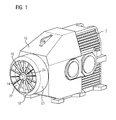
- FIG. 1 shows an embodiment of an air guide cover 10 according to the approach proposed here in one attached to a transmission housing 12 of a transmission, not shown itself state.
- the air guide cover 10 partially covers the transmission housing 12 and correspondingly has a section at least partially covering the transmission housing 12.
- the air guide cover 10 receives a mounted on a drive shaft 14 of the gear housing 12 radial fan 16 and has a radial fan 16 surrounding the conical section 18 and thereafter and further in the direction of the transmission housing 12th a cylindrical portion 20.
- the radial fan 16 sucks ambient air through an opening 22 delimited by the conical section 18 and conveys it inside the air guide hood 10 outwards onto the inner surface of the conical section 18.
- the conical section 18 effects a deflection of the radial air flow in the direction of the transmission housing 12 and optionally, a fan hub 24 provided with a radius or chamfer supports this airflow diversion.
- the deflected air flow at least flows through the cylindrical portion 20 and is there to cool mounted before the transmission and on the drive shaft 14 attachments, such as a planetary gear or a backstop 26 (FIG. FIG. 2 ) or other transmission components, effective.
- the cylindrical portion 20 serves the sewerage of the sucked ambient air in the direction of the gear housing 12 and the bridging and cooling of there optionally additionally attached, usually cylindrical attachments. At the end of the cylindrical portion 20, the channeled air impinges on the transmission housing 12. The impact of the air flow (impingement cooling) on the transmission housing 12 results in a strong cooling of the transmission surrounded by the transmission housing 12 locally. The air is then further guided around the gear housing 12 by means of the air guide cap 10.
- the air guide cover 10 and the radial fan 16 are designed so that a total width of the transmission housing 12 is not exceeded.
- the volume flow and the pressure applied by the radial fan 16 can be influenced by different numbers of radial fan blades, a variation of the width of the radial fan 16 and a variation of the angle of the bevel of the ends of the radial fan blades.
- FIG. 2 shows a section of the illustration according to FIG. 1 in longitudinal section.
- a backstop 26 mounted in the region of the cylindrical section 20 can be seen as an example of an attachable part which can be placed in the region of the cylindrical section 20.
- FIG. 3 shows the air guide 10 of the in FIG. 1 It can be clearly seen in front of the transmission housing 12 surrounding part of the air guide cap 10 whose cylindrical portion 20, the adjoining the cylindrical portion 20 conical portion 18 and the limited of the conical portion 18 opening 22nd During operation, a radial fan 16 mounted on a drive shaft 14 of a transmission provided with the air guide cap 10 sucks ambient air for cooling the transmission by dissipating heat from its gear housing 12 and for cooling attachments optionally located in the area of the cylindrical section 20.
- FIG. 1 shows a possible embodiment of a radial fan 16 with a plurality of regularly spaced radial fan blades.
- the radial fan 16 has this provided with a chamfer fan hub 24. This is in addition to the conical portion 18 of the air guide cover 10 for deflecting the intake air in the direction of the transmission housing 12 effective.
- the radial fan blades are at the same angle as the conical Chamfered section 18, so that a maximum possible length of the radial fan blades and thus the largest possible air flow of the radial fan 16 results.
Landscapes
- Engineering & Computer Science (AREA)
- General Engineering & Computer Science (AREA)
- Mechanical Engineering (AREA)
- General Details Of Gearings (AREA)
- Structures Of Non-Positive Displacement Pumps (AREA)
Abstract
Description
- Die Erfindung betrifft eine Luftleithaube für ein Getriebe, insbesondere eine Luftleithaube für einen Radiallüfter zur Kühlung eines Getriebes, sowie ein Getriebe mit einer Luftleithaube.
- Getriebe werden durch die während des Betriebs anfallende Verlustleistung sehr warm. Eine sich im Getriebe einstellende Öltemperatur limitiert die zulässige mechanische Leistung des jeweiligen Getriebes. Externe Ölkühlanlagen sind oft unerwünscht, so dass eine Kühlung durch die das Getriebe umgebende Luft (Umgebungsluft) erfolgen muss.
- Zu diesem Zweck sind sogenannte Luftleithauben für Getriebe bekannt. Diese werden allgemein eingesetzt, um eine von einem Radial- oder Axiallüfter erzeugte Luftströmung gezielt um das Gehäuse des jeweiligen Getriebes zu lenken. Üblicherweise werden Luftleithauben so ausgeführt, dass diese an einer Ventilatorseite (Saugseite) eine Öffnung zum Ansaugen von Umgebungsluft aufweisen. Ein radialer Bereich um den Lüfter ist rund oder eckig ausgeführt. Angeschlossen an einen solchen ersten Teil der Luftleithaube findet sich ein das Getriebegehäuse einhausender, eckiger Teil.
- Die
DE 198 44 04 U beschreibt einen Lüfter, der in Verbindung mit einer Luftleithaube zur Oberflächenkühlung eines Getriebes eingesetzt wird. Der Lüfter ist von der Luftleithaube umgeben. Die Luftleithaube lenkt den vom Lüfter erzeugten Luftstrom auf das unmittelbar an den Lüfter anschließende Getriebegehäuse. - Die
DE 10 2012 013 351 A1 beschreibt einen Radiallüfter mit zwei Deckscheiben. Der Radiallüfter ist von einer Luftleithaube umschlossen, welche mittels eines Trennblechs ein rein radiales Ansaugen der Umgebungsluft zulässt. Ein Ende der Luftleithaube ist düsenförmig ausgeführt, um die angesaugte Umgebungsluft an das Getriebegehäuse zu leiten. - Eine Besonderheit bei der Verwendung eines Radiallüfters in einer Luftleithaube besteht demnach darin, dass der radiale Luftstrom des Lüfters umgelenkt werden muss. Wenn das Getriebe zylindrische Anbauteile, zum Beispiel ein Anbauteil in Form einer Rücklaufsperre, umfasst, die auf die Antriebswelle montiert werden, ergibt sich als zusätzliches Problem, dass bei einer Kühlung des Getriebes mittels Umgebungsluft ein solches Anbauteil oder eine Mehrzahl von Anbauteilen zu überbrücken sind.
- Der Erfindung liegt daher die Aufgabe zugrunde, eine Lösung zur effizienten Kühlung eines Getriebes mittels eines Radiallüfters vorzuschlagen und gleichzeitig eine Möglichkeit vorzusehen, etwaige Anbauteile zu überbrücken und mit dem zur Kühlung des Getriebes erzeugten Luftstrom ebenfalls zu kühlen.
- Diese Aufgabe wird erfindungsgemäß mittels einer Luftleithaube mit den Merkmalen des Anspruchs 1 sowie mittels eines Getriebes mit einer solchen Luftleithaube gelöst. Dazu ist bei einer Luftleithaube, die für ein Getriebe, nämlich zur Anbringung an dessen Getriebegehäuse, und zur Aufnahme eines Radiallüfters bestimmt ist, vorgesehen, dass die Luftleithaube einen das Getriebegehäuse zumindest zum Teil abdeckenden Abschnitt sowie im Bereich einer Antriebswelle des von dem Getriebegehäuse umgebenen Getriebes und vor dem das Getriebegehäuse abdeckenden Abschnitt einen zylindrischen Abschnitt sowie einen konischen Abschnitt aufweist. Der konische Abschnitt ist zur Aufnahme eines auf der Antriebswelle angebrachten Radiallüfters bestimmt. Der zylindrische Abschnitt ist zur Aufnahme eines oder mehrerer auf der Antriebswelle angebrachter Anbauteile bestimmt.
- Die Positionsangabe "vor dem das Getriebegehäuse abdeckenden Abschnitt" bezieht sich auf die sich beim Betrieb des Getriebes ergebende Luftströmung. Danach befindet sich der Radiallüfter in Strömungsrichtung vor dem Getriebe und dessen Getriebegehäuse. Folglich befindet sich der den Radiallüfter umgebende konische Abschnitt der Luftleithaube vor dem das Getriebegehäuse umgebenden Abschnitt der Luftleithaube.
- Der Vorteil der hier vorgeschlagenen Neuerung besteht darin, dass der konische Abschnitt der Luftleithaube gleichzeitig zur Einhausung des Radiallüfters und zur Umlenkung eines vom Radiallüfter erzeugten Luftstroms in Richtung auf das Getriebegehäuse wirksam ist. Damit lassen sich im Vergleich zu Axiallüftern üblicherweise deutlich preiswertere und zudem drehrichtungsunabhängige Radiallüfter zur effizienten Kühlung eines Getriebes verwenden. Zudem ist der (in Strömungsrichtung) an den konischen Abschnitt anschließende zylindrische Abschnitt zur Kanalisation der Luftströmung in Richtung auf das Getriebegehäuse wirksam. Im Bereich des zylindrischen Abschnitts angebrachte Anbauteile des Getriebes, zum Beispiel eine Rücklaufsperre, eine oder mehrere Planetenradstufen, eine Bremse, ein Messelement oder mehrere Messelemente, werden von der mittels des Radiallüfters angesaugten Umgebungsluft umströmt und damit ebenfalls gekühlt. Die Länge des zylindrischen Abschnitts kann bedarfsweise an eine jeweilige Anzahl und/oder Dimension des oder jedes Anbauteils angepasst werden. Im Anschluss an den zylindrischen Abschnitt der Luftleithaube trifft die mittels des Radiallüfters angesaugte Umgebungsluft auf das Getriebegehäuse (Prallkühlung) und bewirkt dort und im weiteren Verlauf der Luftströmung durch den zwischen Luftleithaube und Getriebegehäuse verbleibenden Zwischenraum die Kühlung des Getriebes.
- Bei einer Ausführungsform des Getriebes mit einer solchen Luftleithaube ist vorgesehen, dass auf einer Antriebswelle des Getriebes ein Radiallüfter angebracht ist und dass die Luftleithaube so ausgeführt ist und so am Gehäuse des Getriebes angebracht ist, dass der konische Abschnitt der Luftleithaube den Radiallüfter umgibt. Der konische Abschnitt der Luftleithaube haust den Radiallüfter ein und bewirkt eine Umleitung des von dem Radiallüfter im Betrieb erzeugten Luftstroms in Richtung auf das Getriebe/Getriebegehäuse.
- Bei einer weiteren Ausführungsform des Getriebes ist vorgesehen, dass an der Antriebswelle und zwischen dem Radiallüfter und dem Getriebe zumindest ein Anbauteil oder mehrere Anbauteile, zum Beispiel weitere Getriebekomponenten, eine Rücklaufsperre, eine oder mehrere Planetenradstufen, eine oder mehrere Bremsen, ein oder mehrere Messelemente usw., angebracht ist bzw. sind und dass der zylindrische Abschnitt das oder jedes Anbauteil umgibt. Auf diese Weise ist gewährleistet, dass die mittels des konischen Abschnitts in Richtung auf das Getriebe/Getriebegehäuse umgelenkte und mittels des Radiallüfters angesaugte Umgebungsluft auch eine Kühlung des oder jedes im Bereich des zylindrischen Abschnitts der Luftleithaube angebrachten Anbauteils bewirkt.
- Nachfolgend wird ein Ausführungsbeispiel der Erfindung anhand der Zeichnung näher erläutert. Einander entsprechende Gegenstände oder Elemente sind in allen Figuren mit den gleichen Bezugszeichen versehen.
- Es zeigen
- FIG 1
- ein Getriebegehäuse mit einer daran angebrachten Luftleithaube,
- FIG 2
- einen vergrößerten Ausschnitt der Darstellung in
FIG 1 im Längsschnitt, - FIG 3
- die Luftleithaube gemäß
FIG 1 und - FIG 4
- einen Radiallüfter.
- Die Darstellung in
FIG 1 zeigt eine Ausführungsform einer Luftleithaube 10 gemäß dem hier vorgeschlagenen Ansatz in einem an einem Getriebegehäuse 12 eines selbst nicht gezeigten Getriebes angebrachten Zustand. Bei der gezeigten Ausführungsform deckt die Luftleithaube 10 das Getriebegehäuse 12 zum Teil ab und weist entsprechend einen das Getriebegehäuse 12 zumindest zum Teil abdeckenden Abschnitt auf. - Gegenüberliegend von dem das Getriebegehäuse 12 zumindest zum Teil abdeckenden Abschnitt nimmt die Luftleithaube 10 einen auf einer Antriebswelle 14 des Getriebegehäuses 12 angebrachten Radiallüfter 16 auf und weist dazu einen den Radiallüfter 16 umgebenden konischen Abschnitt 18 sowie im Anschluss daran und weiter in Richtung auf das Getriebegehäuse 12 einen zylindrischen Abschnitt 20 auf. Der Radiallüfter 16 saugt durch eine durch den konischen Abschnitt 18 begrenzte Öffnung 22 Umgebungsluft an und fördert diese im Innern der Luftleithaube 10 nach außen auf die Innenoberfläche des konischen Abschnitts 18. Der konische Abschnitt 18 bewirkt eine Umlenkung des radialen Luftstroms in Richtung auf das Getriebegehäuse 12 und optional unterstützt eine mit einem Radius oder einer Fase versehene Lüfternabe 24 diese Umlenkung des Luftstroms. Auf dem Weg zum Getriebegehäuse 12 strömt der umgelenkte Luftstrom jedenfalls durch den zylindrischen Abschnitt 20 und ist dort zur Kühlung von vor dem Getriebe und auf die Antriebswelle 14 montierten Anbauteilen, wie zum Beispiel einer Planetenradstufe oder einer Rücklaufsperre 26 (
FIG 2 ) oder sonstigen Getriebekomponenten, wirksam. - Der zylindrische Abschnitt 20 dient der Kanalisation der angesaugten Umgebungsluft in Richtung auf das Getriebegehäuse 12 sowie dem Überbrücken und Kühlen von dort gegebenenfalls zusätzlich angebrachten, meist zylindrischen Anbauteilen. Am Ende des zylindrischen Abschnitts 20 trifft die kanalisierte Luft auf das Getriebegehäuse 12. Durch den Aufprall des Luftstroms (Prallkühlung) auf das Getriebegehäuse 12 wird lokal eine starke Entwärmung des von dem Getriebegehäuse 12 umgebenen Getriebes erzielt. Die Luft wird anschließend mittels der Luftleithaube 10 weiter um das Getriebegehäuse 12 herumgeführt.
- Bei einer bevorzugten Ausführungsform werden die Luftleithaube 10 und der Radiallüfter 16 so ausgeführt, dass eine Gesamtbreite des Getriebegehäuses 12 nicht überschritten wird. Der Volumenstrom sowie der vom Radiallüfter 16 aufgebrachte Druck kann über unterschiedliche Anzahlen von Radiallüfterflügeln, eine Variation der Breite des Radiallüfters 16 sowie eine Variation des Winkels der Abschrägung der Enden der Radiallüfterflügel beeinflusst werden.
- Die Darstellung in
FIG 2 zeigt einen Ausschnitt aus der Darstellung gemäßFIG 1 im Längsschnitt. Hier ist speziell eine im Bereich des zylindrischen Abschnitts 20 angebrachte Rücklaufsperre 26 als Beispiel für ein im Bereich des zylindrischen Abschnitts 20 platzierbares Anbauteil erkennbar. - Die Darstellung in
FIG 3 zeigt die Luftleithaube 10 der inFIG 1 gezeigten Ausführungsform ohne das Getriebegehäuse 12 und ohne einen Radiallüfter 16. Man erkennt deutlich vor dem das Getriebegehäuse 12 umgebenden Teil der Luftleithaube 10 deren zylindrischen Abschnitt 20, den an den zylindrischen Abschnitt 20 anschließenden konischen Abschnitt 18 sowie die von dem konischen Abschnitt 18 begrenzte Öffnung 22. Durch die Öffnung 22 saugt im Betrieb ein auf einer Antriebswelle 14 eines mit der Luftleithaube 10 versehenen Getriebes angebrachter Radiallüfter 16 Umgebungsluft zur Kühlung des Getriebes durch eine Wärmeabfuhr von dessen Getriebegehäuse 12 sowie zur Kühlung von gegebenenfalls im Bereich des zylindrischen Abschnitts 20 befindlichen Anbauteilen an. - Die Darstellung in
FIG 4 zeigt abschließend eine mögliche Ausführungsform eines Radiallüfters 16 mit einer Mehrzahl von regelmäßig beabstandeten Radiallüfterflügeln. Bei der inFIG 4 gezeigten Ausführungsform des Radiallüfters 16 weist dieser eine mit einer Fase versehene Lüfternabe 24 auf. Diese ist zusätzlich zum konischen Abschnitt 18 der Luftleithaube 10 zur Umlenkung der angesaugten Luft in Richtung auf das Getriebegehäuse 12 wirksam. Bei der gezeigten Ausführungsform sind die Radiallüfterflügel im gleichen Winkel wie der konische Abschnitt 18 angeschrägt, so dass sich eine maximal mögliche Länge der Radiallüfterflügel und damit eine möglichst große Luftleistung des Radiallüfters 16 ergibt. - Obwohl die Erfindung im Detail durch das Ausführungsbeispiel näher illustriert und beschrieben wurde, so ist die Erfindung nicht durch das oder die offenbarten Beispiele eingeschränkt und andere Variationen können vom Fachmann hieraus abgeleitet werden, ohne den Schutzumfang der Erfindung zu verlassen.
- Einzelne Aspekte der hier vorgelegten Beschreibung lassen sich kurz wie folgt zusammenfassen: Angegeben werden eine Luftleithaube 10 für ein Getriebe und zur Anbringung an dessen Getriebegehäuse 12, sowie ein Getriebe mit einer Luftleithaube 10, wobei die Luftleithaube 10 einen das Getriebegehäuse 12 zumindest zum Teil abdeckenden Abschnitt und im Bereich einer Antriebswelle 14 einen zylindrischen Abschnitt 20 sowie einen konischen Abschnitt 18 aufweist, wobei der konische Abschnitt 18 zur Aufnahme eines auf der Antriebswelle 14 angebrachten Radiallüfters 16 und der zylindrische Abschnitt 20 zur Aufnahme eines auf der Antriebswelle 14 angebrachten Anbauteils bestimmt ist.
Claims (4)
- Luftleithaube (10) für ein Getriebegehäuse (12) und zur Aufnahme eines Radiallüfters (16),
wobei die Luftleithaube (10) einen das Getriebegehäuse (12) zumindest zum Teil abdeckenden Abschnitt sowie im Bereich einer Antriebswelle (14) eines von dem Getriebegehäuse (12) umgebenen Getriebes vor dem das Getriebegehäuse (12) abdeckenden Abschnitt einen zylindrischen Abschnitt (20) sowie einen konischen Abschnitt (18) aufweist und
wobei der konische Abschnitt (18) zur Aufnahme eines auf der Antriebswelle (14) angebrachten Radiallüfters (16) und der zylindrische Abschnitt (20) zur Aufnahme eines auf der Antriebswelle (14) angebrachten Anbauteils bestimmt ist. - Getriebe mit einem Getriebegehäuse (12) und einer an dem Getriebegehäuse (12) angebrachten Luftleithaube (10) nach Anspruch 1.
- Getriebe nach Anspruch 2, mit einer Antriebswelle (14) und einem auf der Antriebswelle (14) angebrachten Radiallüfter (16), wobei der konische Abschnitt (18) der Luftleithaube (10) den Radiallüfter (16) umgibt.
- Getriebe nach Anspruch 3, mit zumindest einem an der Antriebswelle (14) und zwischen dem Radiallüfter (16) und dem Getriebe angebrachten Anbauteil, wobei der zylindrische Abschnitt (20) das oder jedes Anbauteil umgibt.
Priority Applications (4)
| Application Number | Priority Date | Filing Date | Title |
|---|---|---|---|
| ES15164779T ES2824260T3 (es) | 2015-04-23 | 2015-04-23 | Deflector de aire para una transmisión y transmisión con un deflector de aire |
| EP15164779.9A EP3085997B1 (de) | 2015-04-23 | 2015-04-23 | Luftleithaube für ein getriebe und getriebe mit einer luftleithaube |
| CN201610220800.3A CN106065937B (zh) | 2015-04-23 | 2016-04-11 | 具有导风罩的传动装置 |
| US15/136,288 US9951859B2 (en) | 2015-04-23 | 2016-04-22 | Gearset with an air-guiding cover |
Applications Claiming Priority (1)
| Application Number | Priority Date | Filing Date | Title |
|---|---|---|---|
| EP15164779.9A EP3085997B1 (de) | 2015-04-23 | 2015-04-23 | Luftleithaube für ein getriebe und getriebe mit einer luftleithaube |
Publications (2)
| Publication Number | Publication Date |
|---|---|
| EP3085997A1 true EP3085997A1 (de) | 2016-10-26 |
| EP3085997B1 EP3085997B1 (de) | 2020-07-22 |
Family
ID=53002549
Family Applications (1)
| Application Number | Title | Priority Date | Filing Date |
|---|---|---|---|
| EP15164779.9A Active EP3085997B1 (de) | 2015-04-23 | 2015-04-23 | Luftleithaube für ein getriebe und getriebe mit einer luftleithaube |
Country Status (4)
| Country | Link |
|---|---|
| US (1) | US9951859B2 (de) |
| EP (1) | EP3085997B1 (de) |
| CN (1) | CN106065937B (de) |
| ES (1) | ES2824260T3 (de) |
Cited By (3)
| Publication number | Priority date | Publication date | Assignee | Title |
|---|---|---|---|---|
| CN106382360A (zh) * | 2016-11-16 | 2017-02-08 | 常州耐强传动机械有限公司 | 减速机降压系统 |
| CN108571575A (zh) * | 2017-03-14 | 2018-09-25 | 住友重机械工业株式会社 | 旋转机械 |
| CN111963663A (zh) * | 2020-07-31 | 2020-11-20 | 江苏国茂减速机股份有限公司 | 一种具有散热装置的减速机 |
Families Citing this family (14)
| Publication number | Priority date | Publication date | Assignee | Title |
|---|---|---|---|---|
| DE102017010841A1 (de) * | 2016-12-02 | 2018-06-07 | Sew-Eurodrive Gmbh & Co Kg | Getriebe mit einem Gehäuse, welches ein unteres Gehäuseteil aufweist, auf welches ein oberes Gehäuseteil aufgesetzt ist |
| ES2812207T3 (es) | 2017-06-14 | 2021-03-16 | Flender Gmbh | Transmisión de molino vertical |
| CN107152514B (zh) * | 2017-06-16 | 2023-12-26 | 盐城市禾鼎机械股份有限公司 | 一种具有自散热装置的齿轮 |
| EP3421844B1 (de) | 2017-06-30 | 2020-08-26 | Flender GmbH | Planetenradträgeranordnung, vertikalmühlengetriebe und vertikalmühle |
| EP3460294B1 (de) | 2017-09-20 | 2020-03-25 | Flender GmbH | Getriebe mit ölkühlung |
| US10458534B1 (en) * | 2018-05-31 | 2019-10-29 | Abb Schweiz Ag | Gearbox system with add-on cooling fin panels |
| US10690232B2 (en) * | 2018-05-31 | 2020-06-23 | Abb Schweiz Ag | Machine and gearbox system and cooling therefor |
| US10876800B2 (en) * | 2018-07-12 | 2020-12-29 | Abb Schweiz Ag | Mechanical system with cooling apparatus |
| US11466768B2 (en) | 2018-12-31 | 2022-10-11 | Abb Schweiz Ag | Methods and systems for cooling transmissions |
| US11287025B2 (en) | 2018-12-31 | 2022-03-29 | Abb Schweiz Ag | Cooling units for transmissions |
| DE102020000478A1 (de) | 2019-02-12 | 2020-08-13 | Sew-Eurodrive Gmbh & Co. Kg | Antriebssystem, aufweisend einen Elektromotor, ein Gehäuse und einen einen Lüfter aufweisenden Adapter |
| CN109764121B (zh) * | 2019-03-06 | 2022-11-15 | 重庆茂捷汽车变速器有限公司 | 一种散热型轻量化变速箱 |
| US11174937B2 (en) | 2019-09-23 | 2021-11-16 | Abb Schweiz Ag | Speed reducer cooling fins and method of manufacturing |
| DE102021206105A1 (de) * | 2021-06-15 | 2022-12-15 | Dana Motion Systems Deutschland GmbH | Lüfterabdeckungsbaugruppe für ein Getriebe, Verfahren zu deren Herstellung, Baugruppe und modularer Satz |
Citations (5)
| Publication number | Priority date | Publication date | Assignee | Title |
|---|---|---|---|---|
| DE1984404U (de) | 1966-07-28 | 1968-04-25 | Westdeutsche Getriebewerk Gmbh | Kegelrad- und kegelrad-stirnradgetriebe. |
| DE102005031197A1 (de) * | 2005-07-01 | 2007-01-04 | Sew-Eurodrive Gmbh & Co. Kg | Antrieb und Lüfter |
| DE102008010912A1 (de) * | 2007-02-23 | 2008-08-28 | Sew-Eurodrive Gmbh & Co. Kg | Lüfterrad, System und Getriebebaureihe |
| EP2410210A1 (de) * | 2010-07-22 | 2012-01-25 | Siemens Aktiengesellschaft | Getriebe für industrielle Anwendungen |
| DE102012013351A1 (de) | 2012-07-06 | 2014-05-08 | Sew-Eurodrive Gmbh & Co Kg | Getriebe mit einer Welle |
Family Cites Families (18)
| Publication number | Priority date | Publication date | Assignee | Title |
|---|---|---|---|---|
| US2756614A (en) * | 1954-08-30 | 1956-07-31 | Illinois Tool Works | Gearing unit |
| GB1094709A (en) * | 1965-08-12 | 1967-12-13 | Brown Gear Ind | Improvements in or relating to means for cooling gear units |
| US4414861A (en) * | 1982-02-17 | 1983-11-15 | The Falk Corporation | Gear drive cooling |
| US4872502A (en) * | 1987-09-25 | 1989-10-10 | The Falk Company | Air cooling of enclosed gear drives |
| US5801362A (en) * | 1994-01-14 | 1998-09-01 | Hudson Standard Corporation | Portable electric oven with fan and motor arrangement for improved heated air flow and motor cooling |
| DE102007021604A1 (de) * | 2006-05-09 | 2007-11-15 | Denso Corp., Kariya | Gebläse |
| JP4891172B2 (ja) * | 2007-07-26 | 2012-03-07 | 本田技研工業株式会社 | ベルト式無段変速機の冷却構造。 |
| DE102008017755A1 (de) * | 2008-04-07 | 2009-10-15 | Sew-Eurodrive Gmbh & Co. Kg | Kühlanordnung für ein Getriebe, Getriebe und Antrieb |
| DE102008051874A1 (de) * | 2008-10-16 | 2010-04-22 | Rexnord-Stephan Gmbh & Co. Kg | Vorrichtung mit einem Gehäuse mit mindestens zwei Aufstandsfüßen |
| JP5507985B2 (ja) * | 2009-12-10 | 2014-05-28 | 住友重機械工業株式会社 | 駆動装置の冷却ファン及びその冷却ファン構造 |
| US9599406B2 (en) * | 2010-01-27 | 2017-03-21 | Rexnord Industries, Llc | Transmission having a fluid cooling shroud |
| DE102012000682B4 (de) * | 2012-01-17 | 2024-03-21 | Sew-Eurodrive Gmbh & Co Kg | Lüfteranordnung für ein Getriebe und Getriebe mit einer Lüfteranordnung |
| JP6023448B2 (ja) * | 2012-03-29 | 2016-11-09 | 住友重機械工業株式会社 | 動力伝達装置 |
| JP6063288B2 (ja) * | 2013-02-15 | 2017-01-18 | 住友重機械工業株式会社 | 動力伝達装置 |
| JP2014196768A (ja) * | 2013-03-29 | 2014-10-16 | 住友重機械工業株式会社 | 減速機 |
| CN104343944B (zh) * | 2013-08-08 | 2018-03-27 | 光阳工业股份有限公司 | 车辆传动箱冷却风的导风结构 |
| CN103486238B (zh) * | 2013-10-12 | 2016-04-13 | 山东能源重装集团中传矿用设备制造有限公司 | 风水兼用模块式冷却器及集冷却器一体化的减速器 |
| JP6403623B2 (ja) * | 2015-03-31 | 2018-10-10 | 住友重機械工業株式会社 | 減速装置 |
-
2015
- 2015-04-23 ES ES15164779T patent/ES2824260T3/es active Active
- 2015-04-23 EP EP15164779.9A patent/EP3085997B1/de active Active
-
2016
- 2016-04-11 CN CN201610220800.3A patent/CN106065937B/zh not_active Expired - Fee Related
- 2016-04-22 US US15/136,288 patent/US9951859B2/en active Active
Patent Citations (5)
| Publication number | Priority date | Publication date | Assignee | Title |
|---|---|---|---|---|
| DE1984404U (de) | 1966-07-28 | 1968-04-25 | Westdeutsche Getriebewerk Gmbh | Kegelrad- und kegelrad-stirnradgetriebe. |
| DE102005031197A1 (de) * | 2005-07-01 | 2007-01-04 | Sew-Eurodrive Gmbh & Co. Kg | Antrieb und Lüfter |
| DE102008010912A1 (de) * | 2007-02-23 | 2008-08-28 | Sew-Eurodrive Gmbh & Co. Kg | Lüfterrad, System und Getriebebaureihe |
| EP2410210A1 (de) * | 2010-07-22 | 2012-01-25 | Siemens Aktiengesellschaft | Getriebe für industrielle Anwendungen |
| DE102012013351A1 (de) | 2012-07-06 | 2014-05-08 | Sew-Eurodrive Gmbh & Co Kg | Getriebe mit einer Welle |
Cited By (4)
| Publication number | Priority date | Publication date | Assignee | Title |
|---|---|---|---|---|
| CN106382360A (zh) * | 2016-11-16 | 2017-02-08 | 常州耐强传动机械有限公司 | 减速机降压系统 |
| CN108571575A (zh) * | 2017-03-14 | 2018-09-25 | 住友重机械工业株式会社 | 旋转机械 |
| CN108571575B (zh) * | 2017-03-14 | 2021-11-23 | 住友重机械工业株式会社 | 旋转机械 |
| CN111963663A (zh) * | 2020-07-31 | 2020-11-20 | 江苏国茂减速机股份有限公司 | 一种具有散热装置的减速机 |
Also Published As
| Publication number | Publication date |
|---|---|
| ES2824260T3 (es) | 2021-05-11 |
| EP3085997B1 (de) | 2020-07-22 |
| US20160312877A1 (en) | 2016-10-27 |
| CN106065937B (zh) | 2019-06-04 |
| US9951859B2 (en) | 2018-04-24 |
| CN106065937A (zh) | 2016-11-02 |
Similar Documents
| Publication | Publication Date | Title |
|---|---|---|
| EP3085997B1 (de) | Luftleithaube für ein getriebe und getriebe mit einer luftleithaube | |
| DE102010037617B4 (de) | Luftleiteinrichtung | |
| DE102013225538B4 (de) | Bremsscheibe mit Innenbelüftung | |
| EP2778432A1 (de) | Strömungsgleichrichter | |
| EP3108788A1 (de) | Saugreinigungsgerät | |
| DE10111397B4 (de) | Schutzgitter für Ventilatoren | |
| EP3191740B1 (de) | Radnabengetriebe | |
| DE102014205603A1 (de) | Luftleitvorrichtung für ein Fahrzeug | |
| EP3283793B1 (de) | Getriebe, aufweisend eine welle, ein flanschteil und ein gehäuseteil | |
| DE2743826B2 (de) | Elektromotor, der mit seinem abtriebsseitigen Ende an der Wand einer Arbeitsmaschine, insbesondere Geschirrspülmaschine, befestigt ist | |
| DE102014117962A1 (de) | Elektrisches Antriebssystem mit einer verbesserten Kühlung | |
| DE10158408B4 (de) | Radscheibe eines Kraftfahrzeugrades | |
| DE3208541C1 (de) | Schutzvorrichtung fuer eine Gelenkwelle | |
| EP3231654A1 (de) | Kühlvorrichtung für ein kraftfahrzeug | |
| DE102020111517A1 (de) | Radträgeranordnung einer Vorderachse bzw. Hinterachse eines Kraftfahrzeuges | |
| EP2372163A1 (de) | Lüfterrad | |
| DE112016000029T5 (de) | Arbeitsfahrzeug | |
| WO2018158260A1 (de) | Lüfterrad | |
| DE102010016664A1 (de) | Selbstfahrende landwirtschaftliche Arbeitsmaschine | |
| DE102008038373A1 (de) | Anordnung eines Abschirmblechs | |
| DE68927972T2 (de) | Zusammengesetzter Ventilator für Maschinenkühlung und sonstige Anwendungen | |
| EP3040256B1 (de) | Radkasten eines kraftfahrzeuges | |
| DE102023109693B4 (de) | Schutzvorrichtung für einen optischen Sensor | |
| DE102013212501A1 (de) | Leitschaufelsegment mit stirnseitiger Ausnehmung | |
| DE102019107740A1 (de) | Elektrische Radantriebseinheit zum Antrieb eines Rades eines Kraftfahrzeuges |
Legal Events
| Date | Code | Title | Description |
|---|---|---|---|
| PUAI | Public reference made under article 153(3) epc to a published international application that has entered the european phase |
Free format text: ORIGINAL CODE: 0009012 |
|
| AK | Designated contracting states |
Kind code of ref document: A1 Designated state(s): AL AT BE BG CH CY CZ DE DK EE ES FI FR GB GR HR HU IE IS IT LI LT LU LV MC MK MT NL NO PL PT RO RS SE SI SK SM TR |
|
| AX | Request for extension of the european patent |
Extension state: BA ME |
|
| STAA | Information on the status of an ep patent application or granted ep patent |
Free format text: STATUS: REQUEST FOR EXAMINATION WAS MADE |
|
| 17P | Request for examination filed |
Effective date: 20170406 |
|
| RBV | Designated contracting states (corrected) |
Designated state(s): AL AT BE BG CH CY CZ DE DK EE ES FI FR GB GR HR HU IE IS IT LI LT LU LV MC MK MT NL NO PL PT RO RS SE SI SK SM TR |
|
| RAP1 | Party data changed (applicant data changed or rights of an application transferred) |
Owner name: SIEMENS AKTIENGESELLSCHAFT |
|
| RAP1 | Party data changed (applicant data changed or rights of an application transferred) |
Owner name: FLENDER GMBH |
|
| STAA | Information on the status of an ep patent application or granted ep patent |
Free format text: STATUS: EXAMINATION IS IN PROGRESS |
|
| 17Q | First examination report despatched |
Effective date: 20190624 |
|
| GRAP | Despatch of communication of intention to grant a patent |
Free format text: ORIGINAL CODE: EPIDOSNIGR1 |
|
| STAA | Information on the status of an ep patent application or granted ep patent |
Free format text: STATUS: GRANT OF PATENT IS INTENDED |
|
| INTG | Intention to grant announced |
Effective date: 20200218 |
|
| GRAS | Grant fee paid |
Free format text: ORIGINAL CODE: EPIDOSNIGR3 |
|
| GRAA | (expected) grant |
Free format text: ORIGINAL CODE: 0009210 |
|
| STAA | Information on the status of an ep patent application or granted ep patent |
Free format text: STATUS: THE PATENT HAS BEEN GRANTED |
|
| AK | Designated contracting states |
Kind code of ref document: B1 Designated state(s): AL AT BE BG CH CY CZ DE DK EE ES FI FR GB GR HR HU IE IS IT LI LT LU LV MC MK MT NL NO PL PT RO RS SE SI SK SM TR |
|
| REG | Reference to a national code |
Ref country code: GB Ref legal event code: FG4D Free format text: NOT ENGLISH |
|
| REG | Reference to a national code |
Ref country code: CH Ref legal event code: EP |
|
| REG | Reference to a national code |
Ref country code: DE Ref legal event code: R096 Ref document number: 502015013050 Country of ref document: DE |
|
| REG | Reference to a national code |
Ref country code: AT Ref legal event code: REF Ref document number: 1293690 Country of ref document: AT Kind code of ref document: T Effective date: 20200815 |
|
| REG | Reference to a national code |
Ref country code: IE Ref legal event code: FG4D Free format text: LANGUAGE OF EP DOCUMENT: GERMAN |
|
| REG | Reference to a national code |
Ref country code: FI Ref legal event code: FGE |
|
| REG | Reference to a national code |
Ref country code: LT Ref legal event code: MG4D |
|
| PG25 | Lapsed in a contracting state [announced via postgrant information from national office to epo] |
Ref country code: HR Free format text: LAPSE BECAUSE OF FAILURE TO SUBMIT A TRANSLATION OF THE DESCRIPTION OR TO PAY THE FEE WITHIN THE PRESCRIBED TIME-LIMIT Effective date: 20200722 Ref country code: LT Free format text: LAPSE BECAUSE OF FAILURE TO SUBMIT A TRANSLATION OF THE DESCRIPTION OR TO PAY THE FEE WITHIN THE PRESCRIBED TIME-LIMIT Effective date: 20200722 Ref country code: PT Free format text: LAPSE BECAUSE OF FAILURE TO SUBMIT A TRANSLATION OF THE DESCRIPTION OR TO PAY THE FEE WITHIN THE PRESCRIBED TIME-LIMIT Effective date: 20201123 Ref country code: NO Free format text: LAPSE BECAUSE OF FAILURE TO SUBMIT A TRANSLATION OF THE DESCRIPTION OR TO PAY THE FEE WITHIN THE PRESCRIBED TIME-LIMIT Effective date: 20201022 Ref country code: SE Free format text: LAPSE BECAUSE OF FAILURE TO SUBMIT A TRANSLATION OF THE DESCRIPTION OR TO PAY THE FEE WITHIN THE PRESCRIBED TIME-LIMIT Effective date: 20200722 Ref country code: BG Free format text: LAPSE BECAUSE OF FAILURE TO SUBMIT A TRANSLATION OF THE DESCRIPTION OR TO PAY THE FEE WITHIN THE PRESCRIBED TIME-LIMIT Effective date: 20201022 Ref country code: GR Free format text: LAPSE BECAUSE OF FAILURE TO SUBMIT A TRANSLATION OF THE DESCRIPTION OR TO PAY THE FEE WITHIN THE PRESCRIBED TIME-LIMIT Effective date: 20201023 |
|
| PG25 | Lapsed in a contracting state [announced via postgrant information from national office to epo] |
Ref country code: RS Free format text: LAPSE BECAUSE OF FAILURE TO SUBMIT A TRANSLATION OF THE DESCRIPTION OR TO PAY THE FEE WITHIN THE PRESCRIBED TIME-LIMIT Effective date: 20200722 Ref country code: LV Free format text: LAPSE BECAUSE OF FAILURE TO SUBMIT A TRANSLATION OF THE DESCRIPTION OR TO PAY THE FEE WITHIN THE PRESCRIBED TIME-LIMIT Effective date: 20200722 Ref country code: PL Free format text: LAPSE BECAUSE OF FAILURE TO SUBMIT A TRANSLATION OF THE DESCRIPTION OR TO PAY THE FEE WITHIN THE PRESCRIBED TIME-LIMIT Effective date: 20200722 Ref country code: IS Free format text: LAPSE BECAUSE OF FAILURE TO SUBMIT A TRANSLATION OF THE DESCRIPTION OR TO PAY THE FEE WITHIN THE PRESCRIBED TIME-LIMIT Effective date: 20201122 |
|
| PG25 | Lapsed in a contracting state [announced via postgrant information from national office to epo] |
Ref country code: NL Free format text: LAPSE BECAUSE OF FAILURE TO SUBMIT A TRANSLATION OF THE DESCRIPTION OR TO PAY THE FEE WITHIN THE PRESCRIBED TIME-LIMIT Effective date: 20200722 |
|
| REG | Reference to a national code |
Ref country code: DE Ref legal event code: R097 Ref document number: 502015013050 Country of ref document: DE |
|
| PG25 | Lapsed in a contracting state [announced via postgrant information from national office to epo] |
Ref country code: DK Free format text: LAPSE BECAUSE OF FAILURE TO SUBMIT A TRANSLATION OF THE DESCRIPTION OR TO PAY THE FEE WITHIN THE PRESCRIBED TIME-LIMIT Effective date: 20200722 Ref country code: CZ Free format text: LAPSE BECAUSE OF FAILURE TO SUBMIT A TRANSLATION OF THE DESCRIPTION OR TO PAY THE FEE WITHIN THE PRESCRIBED TIME-LIMIT Effective date: 20200722 Ref country code: EE Free format text: LAPSE BECAUSE OF FAILURE TO SUBMIT A TRANSLATION OF THE DESCRIPTION OR TO PAY THE FEE WITHIN THE PRESCRIBED TIME-LIMIT Effective date: 20200722 Ref country code: SM Free format text: LAPSE BECAUSE OF FAILURE TO SUBMIT A TRANSLATION OF THE DESCRIPTION OR TO PAY THE FEE WITHIN THE PRESCRIBED TIME-LIMIT Effective date: 20200722 Ref country code: RO Free format text: LAPSE BECAUSE OF FAILURE TO SUBMIT A TRANSLATION OF THE DESCRIPTION OR TO PAY THE FEE WITHIN THE PRESCRIBED TIME-LIMIT Effective date: 20200722 |
|
| REG | Reference to a national code |
Ref country code: ES Ref legal event code: FG2A Ref document number: 2824260 Country of ref document: ES Kind code of ref document: T3 Effective date: 20210511 |
|
| REG | Reference to a national code |
Ref country code: DE Ref legal event code: R082 Ref document number: 502015013050 Country of ref document: DE Representative=s name: MICHALSKI HUETTERMANN & PARTNER PATENTANWAELTE, DE |
|
| PLBE | No opposition filed within time limit |
Free format text: ORIGINAL CODE: 0009261 |
|
| STAA | Information on the status of an ep patent application or granted ep patent |
Free format text: STATUS: NO OPPOSITION FILED WITHIN TIME LIMIT |
|
| PG25 | Lapsed in a contracting state [announced via postgrant information from national office to epo] |
Ref country code: AL Free format text: LAPSE BECAUSE OF FAILURE TO SUBMIT A TRANSLATION OF THE DESCRIPTION OR TO PAY THE FEE WITHIN THE PRESCRIBED TIME-LIMIT Effective date: 20200722 |
|
| 26N | No opposition filed |
Effective date: 20210423 |
|
| PG25 | Lapsed in a contracting state [announced via postgrant information from national office to epo] |
Ref country code: SK Free format text: LAPSE BECAUSE OF FAILURE TO SUBMIT A TRANSLATION OF THE DESCRIPTION OR TO PAY THE FEE WITHIN THE PRESCRIBED TIME-LIMIT Effective date: 20200722 |
|
| PG25 | Lapsed in a contracting state [announced via postgrant information from national office to epo] |
Ref country code: SI Free format text: LAPSE BECAUSE OF FAILURE TO SUBMIT A TRANSLATION OF THE DESCRIPTION OR TO PAY THE FEE WITHIN THE PRESCRIBED TIME-LIMIT Effective date: 20200722 |
|
| REG | Reference to a national code |
Ref country code: NL Ref legal event code: MP Effective date: 20200722 |
|
| PG25 | Lapsed in a contracting state [announced via postgrant information from national office to epo] |
Ref country code: MC Free format text: LAPSE BECAUSE OF FAILURE TO SUBMIT A TRANSLATION OF THE DESCRIPTION OR TO PAY THE FEE WITHIN THE PRESCRIBED TIME-LIMIT Effective date: 20200722 |
|
| PG25 | Lapsed in a contracting state [announced via postgrant information from national office to epo] |
Ref country code: LU Free format text: LAPSE BECAUSE OF NON-PAYMENT OF DUE FEES Effective date: 20210423 |
|
| PG25 | Lapsed in a contracting state [announced via postgrant information from national office to epo] |
Ref country code: LI Free format text: LAPSE BECAUSE OF NON-PAYMENT OF DUE FEES Effective date: 20210430 Ref country code: CH Free format text: LAPSE BECAUSE OF NON-PAYMENT OF DUE FEES Effective date: 20210430 |
|
| PG25 | Lapsed in a contracting state [announced via postgrant information from national office to epo] |
Ref country code: IE Free format text: LAPSE BECAUSE OF NON-PAYMENT OF DUE FEES Effective date: 20210423 |
|
| PG25 | Lapsed in a contracting state [announced via postgrant information from national office to epo] |
Ref country code: IS Free format text: LAPSE BECAUSE OF FAILURE TO SUBMIT A TRANSLATION OF THE DESCRIPTION OR TO PAY THE FEE WITHIN THE PRESCRIBED TIME-LIMIT Effective date: 20201122 |
|
| REG | Reference to a national code |
Ref country code: AT Ref legal event code: MM01 Ref document number: 1293690 Country of ref document: AT Kind code of ref document: T Effective date: 20210423 |
|
| PG25 | Lapsed in a contracting state [announced via postgrant information from national office to epo] |
Ref country code: AT Free format text: LAPSE BECAUSE OF NON-PAYMENT OF DUE FEES Effective date: 20210423 |
|
| PG25 | Lapsed in a contracting state [announced via postgrant information from national office to epo] |
Ref country code: HU Free format text: LAPSE BECAUSE OF FAILURE TO SUBMIT A TRANSLATION OF THE DESCRIPTION OR TO PAY THE FEE WITHIN THE PRESCRIBED TIME-LIMIT; INVALID AB INITIO Effective date: 20150423 |
|
| PG25 | Lapsed in a contracting state [announced via postgrant information from national office to epo] |
Ref country code: CY Free format text: LAPSE BECAUSE OF FAILURE TO SUBMIT A TRANSLATION OF THE DESCRIPTION OR TO PAY THE FEE WITHIN THE PRESCRIBED TIME-LIMIT Effective date: 20200722 |
|
| PGFP | Annual fee paid to national office [announced via postgrant information from national office to epo] |
Ref country code: IT Payment date: 20230426 Year of fee payment: 9 Ref country code: FR Payment date: 20230424 Year of fee payment: 9 Ref country code: ES Payment date: 20230627 Year of fee payment: 9 Ref country code: DE Payment date: 20230426 Year of fee payment: 9 |
|
| PGFP | Annual fee paid to national office [announced via postgrant information from national office to epo] |
Ref country code: TR Payment date: 20230419 Year of fee payment: 9 Ref country code: FI Payment date: 20230419 Year of fee payment: 9 |
|
| PGFP | Annual fee paid to national office [announced via postgrant information from national office to epo] |
Ref country code: BE Payment date: 20230419 Year of fee payment: 9 |
|
| PGFP | Annual fee paid to national office [announced via postgrant information from national office to epo] |
Ref country code: GB Payment date: 20230419 Year of fee payment: 9 |
|
| PG25 | Lapsed in a contracting state [announced via postgrant information from national office to epo] |
Ref country code: MK Free format text: LAPSE BECAUSE OF FAILURE TO SUBMIT A TRANSLATION OF THE DESCRIPTION OR TO PAY THE FEE WITHIN THE PRESCRIBED TIME-LIMIT Effective date: 20200722 |
|
| PG25 | Lapsed in a contracting state [announced via postgrant information from national office to epo] |
Ref country code: MT Free format text: LAPSE BECAUSE OF FAILURE TO SUBMIT A TRANSLATION OF THE DESCRIPTION OR TO PAY THE FEE WITHIN THE PRESCRIBED TIME-LIMIT Effective date: 20200722 |
|
| REG | Reference to a national code |
Ref country code: DE Ref legal event code: R119 Ref document number: 502015013050 Country of ref document: DE |
|
| GBPC | Gb: european patent ceased through non-payment of renewal fee |
Effective date: 20240423 |
|
| REG | Reference to a national code |
Ref country code: BE Ref legal event code: MM Effective date: 20240430 |
|
| PG25 | Lapsed in a contracting state [announced via postgrant information from national office to epo] |
Ref country code: DE Free format text: LAPSE BECAUSE OF NON-PAYMENT OF DUE FEES Effective date: 20241105 |
|
| PG25 | Lapsed in a contracting state [announced via postgrant information from national office to epo] |
Ref country code: BE Free format text: LAPSE BECAUSE OF NON-PAYMENT OF DUE FEES Effective date: 20240430 Ref country code: FI Free format text: LAPSE BECAUSE OF NON-PAYMENT OF DUE FEES Effective date: 20240423 |
|
| PG25 | Lapsed in a contracting state [announced via postgrant information from national office to epo] |
Ref country code: GB Free format text: LAPSE BECAUSE OF NON-PAYMENT OF DUE FEES Effective date: 20240423 |
|
| PG25 | Lapsed in a contracting state [announced via postgrant information from national office to epo] |
Ref country code: FR Free format text: LAPSE BECAUSE OF NON-PAYMENT OF DUE FEES Effective date: 20240430 |
|
| PG25 | Lapsed in a contracting state [announced via postgrant information from national office to epo] |
Ref country code: GB Free format text: LAPSE BECAUSE OF NON-PAYMENT OF DUE FEES Effective date: 20240423 Ref country code: FR Free format text: LAPSE BECAUSE OF NON-PAYMENT OF DUE FEES Effective date: 20240430 Ref country code: FI Free format text: LAPSE BECAUSE OF NON-PAYMENT OF DUE FEES Effective date: 20240423 Ref country code: DE Free format text: LAPSE BECAUSE OF NON-PAYMENT OF DUE FEES Effective date: 20241105 Ref country code: BE Free format text: LAPSE BECAUSE OF NON-PAYMENT OF DUE FEES Effective date: 20240430 |
|
| PG25 | Lapsed in a contracting state [announced via postgrant information from national office to epo] |
Ref country code: IT Free format text: LAPSE BECAUSE OF NON-PAYMENT OF DUE FEES Effective date: 20240423 |
|
| REG | Reference to a national code |
Ref country code: ES Ref legal event code: FD2A Effective date: 20250603 |
|
| PG25 | Lapsed in a contracting state [announced via postgrant information from national office to epo] |
Ref country code: ES Free format text: LAPSE BECAUSE OF NON-PAYMENT OF DUE FEES Effective date: 20240424 |