US11466768B2 - Methods and systems for cooling transmissions - Google Patents
Methods and systems for cooling transmissions Download PDFInfo
- Publication number
- US11466768B2 US11466768B2 US16/730,392 US201916730392A US11466768B2 US 11466768 B2 US11466768 B2 US 11466768B2 US 201916730392 A US201916730392 A US 201916730392A US 11466768 B2 US11466768 B2 US 11466768B2
- Authority
- US
- United States
- Prior art keywords
- transmission
- heat pipes
- input shaft
- heat
- housing
- Prior art date
- Legal status (The legal status is an assumption and is not a legal conclusion. Google has not performed a legal analysis and makes no representation as to the accuracy of the status listed.)
- Active, expires
Links
Images


Classifications
-
- F—MECHANICAL ENGINEERING; LIGHTING; HEATING; WEAPONS; BLASTING
- F16—ENGINEERING ELEMENTS AND UNITS; GENERAL MEASURES FOR PRODUCING AND MAINTAINING EFFECTIVE FUNCTIONING OF MACHINES OR INSTALLATIONS; THERMAL INSULATION IN GENERAL
- F16H—GEARING
- F16H57/00—General details of gearing
- F16H57/04—Features relating to lubrication or cooling or heating
- F16H57/0412—Cooling or heating; Control of temperature
- F16H57/0415—Air cooling or ventilation; Heat exchangers; Thermal insulations
- F16H57/0416—Air cooling or ventilation
-
- F—MECHANICAL ENGINEERING; LIGHTING; HEATING; WEAPONS; BLASTING
- F16—ENGINEERING ELEMENTS AND UNITS; GENERAL MEASURES FOR PRODUCING AND MAINTAINING EFFECTIVE FUNCTIONING OF MACHINES OR INSTALLATIONS; THERMAL INSULATION IN GENERAL
- F16H—GEARING
- F16H57/00—General details of gearing
- F16H57/04—Features relating to lubrication or cooling or heating
- F16H57/0412—Cooling or heating; Control of temperature
- F16H57/0415—Air cooling or ventilation; Heat exchangers; Thermal insulations
-
- F—MECHANICAL ENGINEERING; LIGHTING; HEATING; WEAPONS; BLASTING
- F16—ENGINEERING ELEMENTS AND UNITS; GENERAL MEASURES FOR PRODUCING AND MAINTAINING EFFECTIVE FUNCTIONING OF MACHINES OR INSTALLATIONS; THERMAL INSULATION IN GENERAL
- F16H—GEARING
- F16H57/00—General details of gearing
- F16H57/02—Gearboxes; Mounting gearing therein
-
- F—MECHANICAL ENGINEERING; LIGHTING; HEATING; WEAPONS; BLASTING
- F16—ENGINEERING ELEMENTS AND UNITS; GENERAL MEASURES FOR PRODUCING AND MAINTAINING EFFECTIVE FUNCTIONING OF MACHINES OR INSTALLATIONS; THERMAL INSULATION IN GENERAL
- F16H—GEARING
- F16H57/00—General details of gearing
- F16H57/04—Features relating to lubrication or cooling or heating
- F16H57/0412—Cooling or heating; Control of temperature
- F16H57/0415—Air cooling or ventilation; Heat exchangers; Thermal insulations
- F16H57/0417—Heat exchangers adapted or integrated in the gearing
-
- F—MECHANICAL ENGINEERING; LIGHTING; HEATING; WEAPONS; BLASTING
- F16—ENGINEERING ELEMENTS AND UNITS; GENERAL MEASURES FOR PRODUCING AND MAINTAINING EFFECTIVE FUNCTIONING OF MACHINES OR INSTALLATIONS; THERMAL INSULATION IN GENERAL
- F16H—GEARING
- F16H57/00—General details of gearing
- F16H57/04—Features relating to lubrication or cooling or heating
- F16H57/042—Guidance of lubricant
- F16H57/0421—Guidance of lubricant on or within the casing, e.g. shields or baffles for collecting lubricant, tubes, pipes, grooves, channels or the like
- F16H57/0424—Lubricant guiding means in the wall of or integrated with the casing, e.g. grooves, channels, holes
-
- F—MECHANICAL ENGINEERING; LIGHTING; HEATING; WEAPONS; BLASTING
- F16—ENGINEERING ELEMENTS AND UNITS; GENERAL MEASURES FOR PRODUCING AND MAINTAINING EFFECTIVE FUNCTIONING OF MACHINES OR INSTALLATIONS; THERMAL INSULATION IN GENERAL
- F16H—GEARING
- F16H57/00—General details of gearing
- F16H57/04—Features relating to lubrication or cooling or heating
- F16H57/042—Guidance of lubricant
- F16H57/0421—Guidance of lubricant on or within the casing, e.g. shields or baffles for collecting lubricant, tubes, pipes, grooves, channels or the like
- F16H57/0426—Means for guiding lubricant into an axial channel of a shaft
-
- F—MECHANICAL ENGINEERING; LIGHTING; HEATING; WEAPONS; BLASTING
- F16—ENGINEERING ELEMENTS AND UNITS; GENERAL MEASURES FOR PRODUCING AND MAINTAINING EFFECTIVE FUNCTIONING OF MACHINES OR INSTALLATIONS; THERMAL INSULATION IN GENERAL
- F16H—GEARING
- F16H57/00—General details of gearing
- F16H57/04—Features relating to lubrication or cooling or heating
- F16H57/042—Guidance of lubricant
- F16H57/043—Guidance of lubricant within rotary parts, e.g. axial channels or radial openings in shafts
-
- F—MECHANICAL ENGINEERING; LIGHTING; HEATING; WEAPONS; BLASTING
- F16—ENGINEERING ELEMENTS AND UNITS; GENERAL MEASURES FOR PRODUCING AND MAINTAINING EFFECTIVE FUNCTIONING OF MACHINES OR INSTALLATIONS; THERMAL INSULATION IN GENERAL
- F16H—GEARING
- F16H57/00—General details of gearing
- F16H57/04—Features relating to lubrication or cooling or heating
- F16H57/0467—Elements of gearings to be lubricated, cooled or heated
-
- F—MECHANICAL ENGINEERING; LIGHTING; HEATING; WEAPONS; BLASTING
- F16—ENGINEERING ELEMENTS AND UNITS; GENERAL MEASURES FOR PRODUCING AND MAINTAINING EFFECTIVE FUNCTIONING OF MACHINES OR INSTALLATIONS; THERMAL INSULATION IN GENERAL
- F16H—GEARING
- F16H57/00—General details of gearing
- F16H57/04—Features relating to lubrication or cooling or heating
- F16H57/048—Type of gearings to be lubricated, cooled or heated
- F16H57/0493—Gearings with spur or bevel gears
- F16H57/0495—Gearings with spur or bevel gears with fixed gear ratio
-
- F—MECHANICAL ENGINEERING; LIGHTING; HEATING; WEAPONS; BLASTING
- F16—ENGINEERING ELEMENTS AND UNITS; GENERAL MEASURES FOR PRODUCING AND MAINTAINING EFFECTIVE FUNCTIONING OF MACHINES OR INSTALLATIONS; THERMAL INSULATION IN GENERAL
- F16H—GEARING
- F16H57/00—General details of gearing
- F16H57/02—Gearboxes; Mounting gearing therein
- F16H2057/02039—Gearboxes for particular applications
- F16H2057/02069—Gearboxes for particular applications for industrial applications
- F16H2057/02073—Reduction gearboxes for industry
-
- F—MECHANICAL ENGINEERING; LIGHTING; HEATING; WEAPONS; BLASTING
- F16—ENGINEERING ELEMENTS AND UNITS; GENERAL MEASURES FOR PRODUCING AND MAINTAINING EFFECTIVE FUNCTIONING OF MACHINES OR INSTALLATIONS; THERMAL INSULATION IN GENERAL
- F16H—GEARING
- F16H57/00—General details of gearing
- F16H57/04—Features relating to lubrication or cooling or heating
- F16H57/0456—Lubrication by injection; Injection nozzles or tubes therefor
-
- F—MECHANICAL ENGINEERING; LIGHTING; HEATING; WEAPONS; BLASTING
- F16—ENGINEERING ELEMENTS AND UNITS; GENERAL MEASURES FOR PRODUCING AND MAINTAINING EFFECTIVE FUNCTIONING OF MACHINES OR INSTALLATIONS; THERMAL INSULATION IN GENERAL
- F16H—GEARING
- F16H57/00—General details of gearing
- F16H57/04—Features relating to lubrication or cooling or heating
- F16H57/0457—Splash lubrication
Definitions
- One embodiment of the present invention is a unique transmission including a cooling system.
- Other embodiments include apparatuses, systems, devices, hardware, methods, and combinations for cooling transmission components. Further embodiments, forms, features, aspects, benefits, and advantages of the present application shall become apparent from the description and figures provided herewith.
- gear reducer 102 may not be depicted in FIG. 1 .
- the wall 112 of the housing 110 is illustratively embodied as, or otherwise includes, a bottom wall 112 arranged to contact a support surface (not shown).
- the heat pipes 210 illustratively include a set of heat pipes 220 and a set of heat pipes 230 that are arranged in the bottom wall 112 .
- the set of heat pipes 230 are arranged in the bottom wall 112 perpendicular, or at least generally perpendicular, to the set of heat pipes 220 .
- the wall 116 of the housing 110 is illustratively embodied as, or otherwise includes, a front wall 116 that may be arranged in confronting relation with a housing of a rotational power source or other drive unit.
- the front wall 116 is arranged perpendicular to, and interconnected with, the bottom and top walls 112 , 114 .
- the heat pipes 210 illustratively include a set of heat pipes 260 arranged in the front wall 116 .
- the wall 120 of the housing 110 is illustratively embodied as, or otherwise includes, a side wall 120 .
- the side wall 120 is arranged perpendicular to, and interconnected with, the bottom and top walls 112 , 114 and the front and back walls 116 , 118 .
- the heat pipes 210 illustratively include a set of heat pipes 280 and a set of heat pipes 390 arranged in the side wall 120 . As depicted in FIGS. 2 and 3 , the set of heat pipes 390 are arranged in the side wall 120 perpendicular, or at least generally perpendicular, to the set of heat pipes 280 .
- the wall 122 of the housing 110 is illustratively embodied as, or otherwise includes, a side wall 122 arranged opposite the side wall 120 .
- the side wall 122 is arranged perpendicular to, and interconnected with, the bottom and top walls 112 , 114 and the front and back walls 116 , 118 .
- the illustrative heat pipes 210 may include one or more sets of heat pipes arranged in the side wall 122 .
- two sets of heat pipes may be arranged in the side wall 122 in similar fashion to the arrangement of the sets of heat pipes 280 , 390 in the side wall 120 .
- the heat pipes 210 cooperatively form a criss-crossed and/or lattice-type arrangement in the housing 110 .
- a criss-crossed and/or lattice-type arrangement may be cooperatively formed by one or more of the following: (i) the sets of heat pipes 220 , 230 ; (ii) the sets of heat pipes 240 , 250 ; (iii) the sets of heat pipes 280 , 390 ; and (iv) the set(s) of heat pipes arranged in the side wall 122 .
- the heat pipes 210 may be interconnected with, and/or fluidly coupled to, one another.
- the housing 110 is constructed from metallic materials and fabricated by a casting process.
- the housing 110 may have another suitable construction, such as a construction from polymeric, plaster, or concrete materials, for example. Additionally, in other embodiments, it should be appreciated that the housing 110 may be fabricated by another suitable manufacturing process.
- FIG. 2 is an isometric cutaway view of the housing 110 while many other components are removed for better illustration.
- FIG. 3 is another isometric cutaway view of the housing 110 .
- a group of heat pipes 210 are distributed within the walls 112 - 122 .
- the heat pipes 210 may be either embedded during casting of the housing 110 or fabricated through a machining process after the casting process.
- the cross sections of the heat pipes 210 are not limited to the square shapes shown in FIG. 2 and FIG. 3 .
- the cross sections may be fabricated into different shapes such as circle, semi-circle, triangle and trapezoid for different purposes.
- the circular or semi-circular cross sections may be superior in strength while the square cross sections may provide a maximum surface area to the heat source.
- an illustrative input shaft 400 is configured to receive rotational power from a rotational power source.
- the input shaft 400 is included in, or otherwise adapted for use with, the gear reducer 102 such that the input shaft 400 is embodied as an input shaft of the gear reducer 102 .
- the input shaft 400 may be included in the gear reducer 102 in lieu of the input shaft 104 , in which case the input shaft 400 may be coupled to, and extend outside of, the front wall 116 of the housing 110 , for example.
- At least one of the components 140 is formed integrally with the input shaft 400 and supplied with lubricating fluid stored by the sump 132 in use of the gear reducer 102 .
- a gear 442 is formed integrally with the input shaft 400 and supplied with lubricating fluid stored by the sump 132 in use of the gear reducer 102 .
- the input shaft 400 may therefore be referred to as a geared shaft 400 embodied as a one-piece, monolithic component.
- the gear 442 is a component configured for lubrication by a dip or splash lubrication technique.
- the illustrative gear 442 is at least partially immersed in lubricating fluid stored by the sump 132 .
- the illustrative shaft 400 includes an end 402 and an end 404 arranged opposite the end 402 .
- the end 402 is defined by the gear 442 and the end 404 may be coupled to a rotational power source (e.g., an electric motor).
- the shaft 400 i.e., excluding the gear 442
- the shaft 400 is a generally cylindrical part that extends about a central axis CA between the end 402 and the end 404 .
- a cooling system 500 is arranged in, and supported by, the input shaft 400 .
- the cooling system 500 and methods therefor exemplify another embodiment of the present disclosure.
- the cooling system 500 includes heat pipes 510 extending through the input shaft 400 that are configured to dissipate heat generated by the components 140 during operation thereof to cool the lubricating fluid stored by the sump 132 in use of the gear reducer 102 .
- a typical geared shaft 400 may be a monolithic component.
- the geared shaft 400 may have one gear-end 402 immersed in the oil sump 132 within the enclosed gear reducer 102 and the other end 404 extended out of the reducer housing 110 to connect to an electric motor.
- the geared shaft 400 may be generally in cylindrical shape with various sections of different diameters, except for the gear-end 402 where gear teeth 406 may be fabricated and the other end 404 where a keyway 408 may be located.
- the geared shaft 400 may be constructed such that a plurality of heat pipes 510 extending within the geared shaft 400 between the gear-end 402 and the other end 404 effectively transfer the heat generated in the oil sump 132 to the ambient.
- This group of heat pipes 510 may be fabricated through the machining process since the geared shaft 400 may typically be made from the machining process.
- the cross sections of the heat pipes 510 may be fabricated to different shapes that depend on the function of the heat pipes 510 .
- One particular feature of the geared shaft 400 is that there are a number of heat pipes 510 extending near the end 404 of the shaft 402 that connects to an electric motor.
- the heat pipes 510 each include an end 512 and an end 514 arranged opposite the end 512 .
- the end 512 is located adjacent the end 402 of the input shaft 400
- the end 514 is located adjacent the end 404 of the input shaft 400 .
- the end 512 of each of the heat pipes 510 is arranged radially outward (i.e., outward in a radial direction indicated by arrow R) of the end 514 of each of the heat pipes 510 relative to the central axis CA. Therefore, each of the heat pipes 510 extends through the input shaft 400 at an angle to the central axis CA. Put another way, each of the heat pipes 510 are inclined with respect to the central axis CA such that the ends 512 are farther away from the central axis CA (i.e., in the radial direction R) than the ends 514 .
- the cooling system 500 in addition to the heat pipes 510 , includes feed ports 520 each fluidly coupled, or otherwise in fluid communication with, one of the heat pipes 510 to supply a working fluid thereto in use of the gear reducer 102 .
- the feed ports 520 are located closer to the end 404 of the input shaft 400 than the end 402 thereof.
- Each of the feed ports 520 extends through the input shaft 400 toward the central axis CA in the radial direction R to open into one of the heat pipes 510 .
- FIG. 5 is a sectional view of the geared shaft 400 of FIG. 4 .
- the geared shaft 400 may have heat pipes 510 oriented such that the heat pipes 510 (e.g., central axes of the heat pipes 510 ) are inclined with respect to the central axis CA of the shaft 400 .
- ends 512 of the heat pipes 510 adjacent to the gear-end 402 may be farther from the central shaft axis CA than the ends 514 .
- the heat pipes 510 may spin around the geared shaft axis CA.
- These passages 520 may be constructed in a spiral pattern to provide channels for the vapor transporting to a supplementary heat exchanger, such as the supplementary heat exchanger 900 (see FIG. 9 ), for example.
- the heat pipes 510 are illustratively circumferentially spaced from one another around the central axis CA. More specifically, the heat pipes 510 are circumferentially spaced from one another around the central axis CA in a symmetric fashion such that the heat pipes 510 are equidistant, or at least substantially equidistant, from the central axis CA.
- the heat pipes 510 include eight heat pipes. Consequently, the feed ports 520 illustratively include eight feed ports.
- the heat pipes 510 may include another suitable number of heat pipes and the feed ports 520 may include another suitable number of feed ports.
- FIG. 6 is a section view of the geared shaft 400 of FIG. 4 along line 6 - 6 .
- the geared shaft 400 may be generally cylindrical with various diameters and may define the central shaft axis CA.
- the heat pipes 510 in the geared shaft 400 may be aligned symmetrically around the central shaft axis CA to maintain balance momentum during rotation.
- the number of heat pipes 510 may depend on the heat input and available space within the geared shaft 400 and may not limited to the eight heat pipes 510 shown in FIG. 6 .
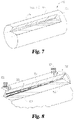
- an illustrative heat pipe 700 is adapted for use with the gear reducer 102 such that the heat pipe 700 may be included in at least one of the cooling systems 200 , 500 .
- each of the heat pipes 210 may be embodied as, or otherwise include, the heat pipe 700 .
- each of the heat pipes 510 may be embodied as, or otherwise include, the heat pipe 700 .
- the heat pipe 700 may have an internal wall 704 that is tapered such that the heat pipe 700 has a non-constant cross-sectional area. That is, one region of the heat pipe 700 (e.g., a region in relatively close proximity to an evaporator section 820 ) may have a cross-sectional area different from another region of the heat pipe 700 (e.g., a region in relatively close proximity to a condenser section 830 ).
- the construction of the illustrative heat pipe 700 depends on the working fluid contained therein.
- the heat pipe 700 has a metallic construction.
- the heat pipe 700 may be formed from copper materials and the working fluid may be water.
- the heat pipe 700 may be formed from aluminum materials and the working fluid may be ammonia.
- the heat pipe 700 may be formed from copper, aluminum, stainless steel, cesium, potassium, sodium, or refractory materials, and the working fluid may be helium, mercury, sodium, indium, alcohol, ethanol, refrigerant, R134a, nitrogen, oxygen, neon, hydrogen, or lithium.
- centrifugal forces associated with rotation of the input shaft 400 may propel liquid working fluid from the condenser section 830 to the evaporator section 820 along the wall 704 .
- inclusion of a wick in the heat pipe 700 that is made from materials different from the heat pipe 700 may be unnecessary.
- the fan-blade heat exchanger 902 may include one or more heat pipes 1010 , a cylindrical hub 904 , and a plurality of fan blades 906 . It should be appreciated that the heat pipes 1010 in the fan-blade heat exchanger 902 may have multiple configurations.
- One possible configuration may be comprised of heat pipes 1010 having semi-circular cross-sectional shapes as shown in FIG. 10 . This may be accomplished by using a cylindrical surface on the geared shaft 400 and machined grooves on a bore surface of the cylindrical hub 904 .
- Another possible configuration may consist of heat pipes 1010 with circular cross sections by grooving with semi-circular cross sections on a cylindrical surface of the geared shaft 400 and on a bore surface of the cylindrical hub 904 .
- the present invention relates generally to a method and system for cooling an industrial gear reducer and, more particularly, to a gear reducer with a totally enclosed housing.
- the present invention may improve the thermal power rating, performance, and service life of gear reducers.
- the invention may be applicable to industries such as mining, aggregate, grain, power plants, wood products, and metals.
- Applications may include conveyors, bucket elevators, crushers/breakers, feeders, mills, and kilns.
- dip lubrication also referred as to splash lubrication
- the rotating components may be immersed in an oil sump, and the motion of the components may supply the circulation necessary to lubricate gear meshes and bearings.
- jet lubrication an extension of a circulating oil system including dedicated scavenge pump, pipes, nozzles, and oil reservoir may be required to provided pressurized oil jets into the gear meshes and bearings.
- Dip lubrication may be preferred for enclosed gear reducers in the aggregate, cement, air handling, oil and gas, mining, elevator, crane, and food processing industries because of its lower cost and simplicity. As a result, maintaining an acceptable oil temperature in the oil sump may prolong the service life of an enclosed gear reducer.
- the rotational motion of gears and bearings in an enclosed gear reducer may cause oil foam that is a collection of small bubbles of air accumulated on or near the surface of the oil.
- Oil foam may be an efficient thermal insulator.
- the presence of air bubbles in the oil may cause overheating in the pump used for oil-to-air and oil-to-water heat exchangers, and reduce heat transfer effectiveness in the heat exchangers.
- the cooling system may be supported by the housing, and the cooling system may include plurality of heat pipes arranged in the plurality of walls of the housing that are configured to dissipate heat generated by the plurality of components during operation thereof to cool the lubricating fluid stored by the sump in use of the transmission.
- the plurality of heat pipes may cooperatively form a criss-crossed arrangement.
- each of the plurality of heat pipes may include a first end located adjacent the first end of the input shaft and a second end opposite the first end that is located adjacent the second end of the input shaft, and the first end of each of the plurality of heat pipes may be arranged radially outward of the second end of each of the plurality of heat pipes relative to the central axis.
- the plurality of heat pipes may be circumferentially spaced around the central axis in a symmetric fashion.
- each of the plurality of feed ports may extend through the input shaft toward the central axis in a radial direction to open into one of the plurality of heat pipes.
- the at least one of the plurality of components may be a gear that is at least partially immersed in lubricating fluid stored by the sump.
- At least one of the plurality of components may be coupled to the input shaft and supplied with lubricating fluid stored by the sump in use of the transmission.
- the cooling system may be supported by the input shaft, and the cooling system may include a plurality of heat pipes extending through the input shaft that are configured to dissipate heat generated by the plurality of components during operation thereof to cool the lubricating fluid stored by the sump in use of the transmission.
- the heat exchanger may be configured to dissipate heat generated by the plurality of components during operation thereof to cool the lubricating fluid stored by the sump in cooperation with the cooling system in use of the transmission.
- the heat exchanger may include a central hub, a plurality of blades extending outwardly from the central hub, and a plurality of heat pipes extending through the central hub.
- the heat exchanger may include a plurality of feed passages each fluidly coupled to one of the plurality of heat pipes of the heat exchanger to supply a working fluid thereto in use of the transmission, and each of the plurality of feed passages may extend through the central hub in a radial direction to open into one of the plurality of heat pipes of the heat exchanger.
- the central hub may be configured for rotation about a hub axis in use of the transmission such that the heat exchanger moves air toward the housing to facilitate dissipation of heat generated by the plurality of components during operation thereof.
Abstract
Description
Claims (18)
Priority Applications (1)
| Application Number | Priority Date | Filing Date | Title |
|---|---|---|---|
| US16/730,392 US11466768B2 (en) | 2018-12-31 | 2019-12-30 | Methods and systems for cooling transmissions |
Applications Claiming Priority (2)
| Application Number | Priority Date | Filing Date | Title |
|---|---|---|---|
| US201862786852P | 2018-12-31 | 2018-12-31 | |
| US16/730,392 US11466768B2 (en) | 2018-12-31 | 2019-12-30 | Methods and systems for cooling transmissions |
Publications (2)
| Publication Number | Publication Date |
|---|---|
| US20200208730A1 US20200208730A1 (en) | 2020-07-02 |
| US11466768B2 true US11466768B2 (en) | 2022-10-11 |
Family
ID=71123775
Family Applications (1)
| Application Number | Title | Priority Date | Filing Date |
|---|---|---|---|
| US16/730,392 Active 2040-03-20 US11466768B2 (en) | 2018-12-31 | 2019-12-30 | Methods and systems for cooling transmissions |
Country Status (1)
| Country | Link |
|---|---|
| US (1) | US11466768B2 (en) |
Families Citing this family (4)
| Publication number | Priority date | Publication date | Assignee | Title |
|---|---|---|---|---|
| CN112888880A (en) * | 2018-10-12 | 2021-06-01 | 索尤若驱动有限及两合公司 | Retarder with a retarder housing |
| CN112747108B (en) * | 2020-12-30 | 2022-05-24 | 苏州绿科智能机器人研究院有限公司 | Speed reducer with ventilation structure |
| CN113028039B (en) * | 2021-03-09 | 2022-08-23 | 陈东红 | Heat dissipation device for speed reducer |
| CN113738861B (en) * | 2021-09-30 | 2023-03-03 | 安徽省含山县皖中减速机械有限公司 | Speed reducer heat dissipation shell of concatenation formula |
Citations (57)
| Publication number | Priority date | Publication date | Assignee | Title |
|---|---|---|---|---|
| US1991618A (en) | 1930-11-03 | 1935-02-19 | Borg Warner | Radiating type oil pan for internal combustion engines |
| US2583751A (en) | 1948-10-27 | 1952-01-29 | Falk Corp | Air-cooled gear set |
| US3476177A (en) | 1967-02-16 | 1969-11-04 | Philips Corp | Contact cooling and mounting device for a discharge tube |
| US3550678A (en) | 1969-04-01 | 1970-12-29 | United Aircraft Prod | Surface radiator |
| US4022272A (en) | 1975-11-14 | 1977-05-10 | Chester O. Houston, Jr. | Transmission fluid heat radiator |
| US4074590A (en) | 1974-08-07 | 1978-02-21 | Helmut Jorg | Arrangement for cooling a lubricant-filled, finned gear case by means of a built-in fan |
| US4414861A (en) | 1982-02-17 | 1983-11-15 | The Falk Corporation | Gear drive cooling |
| WO1991004427A1 (en) | 1989-09-23 | 1991-04-04 | Zahnradfabrik Friedrichshafen Ag | Housing for a gearbox |
| US5193415A (en) | 1991-06-04 | 1993-03-16 | Bruno's Automotive Products Inc. | Continuous radial shield for automatic transmission |
| EP0623767A1 (en) | 1993-05-07 | 1994-11-09 | KCI Konecranes International Corporation | Device for cooling the gear system of a crane |
| US5579830A (en) | 1995-11-28 | 1996-12-03 | Hudson Products Corporation | Passive cooling of enclosures using heat pipes |
| US5816320A (en) | 1997-01-10 | 1998-10-06 | J.I.T. Engineering, Inc. | Radiator fin construction |
| EP0990820A2 (en) * | 1998-10-02 | 2000-04-05 | DaimlerChrysler AG | Motor reduction gear with common cooling |
| US6210042B1 (en) | 1997-06-19 | 2001-04-03 | Qian Wang | Isothermal journal bearing |
| US6415855B2 (en) | 2000-04-17 | 2002-07-09 | Nordon Cryogenie Snc | Corrugated fin with partial offset for a plate-type heat exchanger and corresponding plate-type heat exchanger |
| US6425293B1 (en) | 1999-03-13 | 2002-07-30 | Textron Systems Corporation | Sensor plug |
| US6691831B1 (en) | 1999-09-29 | 2004-02-17 | Fuji Jukogyo Kabushiki Kaisha | Splashing oil lubrication type internal combustion engine |
| US6761546B2 (en) | 2000-06-28 | 2004-07-13 | Coperion Werner & Pfleiderer Gmbh & Co. Kg | Gear pump having bearings with cooling ducts |
| US20050151554A1 (en) | 2004-01-13 | 2005-07-14 | Cookson Electronics, Inc. | Cooling devices and methods of using them |
| US6919504B2 (en) | 2002-12-19 | 2005-07-19 | 3M Innovative Properties Company | Flexible heat sink |
| DE102004022863A1 (en) | 2004-05-06 | 2005-12-01 | Sew-Eurodrive Gmbh & Co. Kg | Gear, has cover and housing, which are tightly and detachably combinable, where cover is made up of aluminum-die casting part and has cooling device with cooling finger, and ventilator or device for driving and/or moving air |
| JP3757765B2 (en) | 2000-06-23 | 2006-03-22 | いすゞ自動車株式会社 | Transmission case structure |
| US20060231337A1 (en) * | 2005-04-11 | 2006-10-19 | The Falk Corporation | Elevated oil reservoir collection and distribution system |
| US7231767B2 (en) | 2004-04-16 | 2007-06-19 | Pratt & Whitney Canada Corp. | Forced air cooling system |
| US7443062B2 (en) | 2004-09-30 | 2008-10-28 | Reliance Electric Technologies Llc | Motor rotor cooling with rotation heat pipes |
| US7569955B2 (en) | 2006-06-19 | 2009-08-04 | Thermal Motor Innovations, Llc | Electric motor with heat pipes |
| US7687945B2 (en) | 2004-09-25 | 2010-03-30 | Bluwav Systems LLC. | Method and system for cooling a motor or motor enclosure |
| US7975804B2 (en) * | 2007-04-10 | 2011-07-12 | Aisin Ai Co., Ltd. | Lubricating structure for transmission |
| US8410350B2 (en) | 2006-12-11 | 2013-04-02 | Ns Acquisition Llc | Modular solar panels with heat exchange |
| DE102011087201A1 (en) * | 2011-11-28 | 2013-05-29 | Zf Friedrichshafen Ag | Rotating shaft for oiling system of vehicle, has transverse bores are arranged along the rotation direction of shaft, with angle between lower prioritized transverse-bore and higher prioritized transverse bore set to specific range |
| US8556585B2 (en) * | 2009-12-10 | 2013-10-15 | Sumitomo Heavy Industries, Ltd. | Cooling fan for driving device and cooling fan structure |
| US8833193B2 (en) | 2009-03-25 | 2014-09-16 | Sew-Eurodrive Gmbh & Co. Kg | Gear unit |
| US8967334B2 (en) | 2009-03-25 | 2015-03-03 | Sew-Eurodrive Gmbh & Co. Kg | Gear unit at least partially filled with oil |
| US8973458B2 (en) | 2009-03-25 | 2015-03-10 | Sew-Eurodrive Gmbh & Co. Kg | Gear unit |
| US9062754B2 (en) | 2009-03-25 | 2015-06-23 | Sew-Eurodrive Gmbh & Co. Kg | Gear unit |
| US20150289850A1 (en) | 2014-04-15 | 2015-10-15 | Tyco Electronics Corporation | Heat Dissipation Assemblies |
| US9272777B2 (en) * | 2012-10-26 | 2016-03-01 | Textron Innovations Inc. | Helicopter gearbox auxiliary cooling system |
| US9366332B2 (en) * | 2012-03-29 | 2016-06-14 | Sumitomo Heavy Industries, Ltd. | Power transmission device |
| US9599406B2 (en) | 2010-01-27 | 2017-03-21 | Rexnord Industries, Llc | Transmission having a fluid cooling shroud |
| DE102015222892A1 (en) * | 2015-11-19 | 2017-05-24 | Zf Friedrichshafen Ag | Transmission shaft with lubricant delivery structure and gearbox |
| US9756759B2 (en) * | 2013-02-15 | 2017-09-05 | Sumitomo Heavy Industries, Ltd. | Power transmission apparatus |
| US9856759B2 (en) | 2012-12-07 | 2018-01-02 | Schaeffler Technologies AG & Co. KG | Camshaft adjuster |
| US9951859B2 (en) | 2015-04-23 | 2018-04-24 | Flender Gmbh | Gearset with an air-guiding cover |
| US10058008B2 (en) | 2013-10-29 | 2018-08-21 | Tai-Her Yang | Temperature control system having adjacently-installed temperature equalizer and heat transfer fluid and application device thereof |
| US20180299210A1 (en) | 2015-10-08 | 2018-10-18 | Linde Aktiengesellschaft | Fin for a plate heat exchanger and method for producing same |
| US10151380B2 (en) * | 2015-09-29 | 2018-12-11 | Mazda Motor Corporation | Transmission and manufacturing method of the same |
| US10221935B2 (en) * | 2015-03-31 | 2019-03-05 | Sumitomo Heavy Industries, Ltd. | Speed reduction apparatus |
| US10247296B2 (en) * | 2016-12-12 | 2019-04-02 | General Electric Company | Additively manufactured gearbox with integral heat exchanger |
| US10260817B2 (en) | 2015-08-12 | 2019-04-16 | Mahle International Gmbh | Stacked-plate heat exchanger |
| US10330174B2 (en) * | 2017-11-09 | 2019-06-25 | General Electric Company | Gear assembly for a wind turbine gearbox having a flexible pin shaft and carrier |
| US10458534B1 (en) | 2018-05-31 | 2019-10-29 | Abb Schweiz Ag | Gearbox system with add-on cooling fin panels |
| US20190368502A1 (en) | 2018-05-31 | 2019-12-05 | Abb Schweiz Ag | System having machine and fan |
| US20190368596A1 (en) | 2018-05-31 | 2019-12-05 | Abb Schweiz Ag | Machine and gearbox system with air cooling |
| US20190368595A1 (en) | 2018-05-31 | 2019-12-05 | Abb Schweiz Ag | Machine and gearbox system and cooling therefor |
| DE102019001493A1 (en) * | 2019-03-04 | 2020-09-10 | Daimler Ag | Component for a vehicle transmission, as well as a method for producing such a component |
| US10876800B2 (en) * | 2018-07-12 | 2020-12-29 | Abb Schweiz Ag | Mechanical system with cooling apparatus |
| US20210199190A1 (en) * | 2019-12-26 | 2021-07-01 | Sumitomo Heavy Industries, Ltd. | Cooling tower speed reducer |
-
2019
- 2019-12-30 US US16/730,392 patent/US11466768B2/en active Active
Patent Citations (58)
| Publication number | Priority date | Publication date | Assignee | Title |
|---|---|---|---|---|
| US1991618A (en) | 1930-11-03 | 1935-02-19 | Borg Warner | Radiating type oil pan for internal combustion engines |
| US2583751A (en) | 1948-10-27 | 1952-01-29 | Falk Corp | Air-cooled gear set |
| US3476177A (en) | 1967-02-16 | 1969-11-04 | Philips Corp | Contact cooling and mounting device for a discharge tube |
| US3550678A (en) | 1969-04-01 | 1970-12-29 | United Aircraft Prod | Surface radiator |
| US4074590A (en) | 1974-08-07 | 1978-02-21 | Helmut Jorg | Arrangement for cooling a lubricant-filled, finned gear case by means of a built-in fan |
| US4022272A (en) | 1975-11-14 | 1977-05-10 | Chester O. Houston, Jr. | Transmission fluid heat radiator |
| US4414861A (en) | 1982-02-17 | 1983-11-15 | The Falk Corporation | Gear drive cooling |
| WO1991004427A1 (en) | 1989-09-23 | 1991-04-04 | Zahnradfabrik Friedrichshafen Ag | Housing for a gearbox |
| US5193415A (en) | 1991-06-04 | 1993-03-16 | Bruno's Automotive Products Inc. | Continuous radial shield for automatic transmission |
| EP0623767A1 (en) | 1993-05-07 | 1994-11-09 | KCI Konecranes International Corporation | Device for cooling the gear system of a crane |
| US5579830A (en) | 1995-11-28 | 1996-12-03 | Hudson Products Corporation | Passive cooling of enclosures using heat pipes |
| US5816320A (en) | 1997-01-10 | 1998-10-06 | J.I.T. Engineering, Inc. | Radiator fin construction |
| US6210042B1 (en) | 1997-06-19 | 2001-04-03 | Qian Wang | Isothermal journal bearing |
| EP0990820A2 (en) * | 1998-10-02 | 2000-04-05 | DaimlerChrysler AG | Motor reduction gear with common cooling |
| US6425293B1 (en) | 1999-03-13 | 2002-07-30 | Textron Systems Corporation | Sensor plug |
| US6691831B1 (en) | 1999-09-29 | 2004-02-17 | Fuji Jukogyo Kabushiki Kaisha | Splashing oil lubrication type internal combustion engine |
| US6415855B2 (en) | 2000-04-17 | 2002-07-09 | Nordon Cryogenie Snc | Corrugated fin with partial offset for a plate-type heat exchanger and corresponding plate-type heat exchanger |
| JP3757765B2 (en) | 2000-06-23 | 2006-03-22 | いすゞ自動車株式会社 | Transmission case structure |
| US6761546B2 (en) | 2000-06-28 | 2004-07-13 | Coperion Werner & Pfleiderer Gmbh & Co. Kg | Gear pump having bearings with cooling ducts |
| US6919504B2 (en) | 2002-12-19 | 2005-07-19 | 3M Innovative Properties Company | Flexible heat sink |
| US20050151554A1 (en) | 2004-01-13 | 2005-07-14 | Cookson Electronics, Inc. | Cooling devices and methods of using them |
| US7231767B2 (en) | 2004-04-16 | 2007-06-19 | Pratt & Whitney Canada Corp. | Forced air cooling system |
| DE102004022863A1 (en) | 2004-05-06 | 2005-12-01 | Sew-Eurodrive Gmbh & Co. Kg | Gear, has cover and housing, which are tightly and detachably combinable, where cover is made up of aluminum-die casting part and has cooling device with cooling finger, and ventilator or device for driving and/or moving air |
| US7687945B2 (en) | 2004-09-25 | 2010-03-30 | Bluwav Systems LLC. | Method and system for cooling a motor or motor enclosure |
| US7443062B2 (en) | 2004-09-30 | 2008-10-28 | Reliance Electric Technologies Llc | Motor rotor cooling with rotation heat pipes |
| US20060231337A1 (en) * | 2005-04-11 | 2006-10-19 | The Falk Corporation | Elevated oil reservoir collection and distribution system |
| US7569955B2 (en) | 2006-06-19 | 2009-08-04 | Thermal Motor Innovations, Llc | Electric motor with heat pipes |
| US8410350B2 (en) | 2006-12-11 | 2013-04-02 | Ns Acquisition Llc | Modular solar panels with heat exchange |
| US7975804B2 (en) * | 2007-04-10 | 2011-07-12 | Aisin Ai Co., Ltd. | Lubricating structure for transmission |
| US8833193B2 (en) | 2009-03-25 | 2014-09-16 | Sew-Eurodrive Gmbh & Co. Kg | Gear unit |
| US8967334B2 (en) | 2009-03-25 | 2015-03-03 | Sew-Eurodrive Gmbh & Co. Kg | Gear unit at least partially filled with oil |
| US8973458B2 (en) | 2009-03-25 | 2015-03-10 | Sew-Eurodrive Gmbh & Co. Kg | Gear unit |
| US9062754B2 (en) | 2009-03-25 | 2015-06-23 | Sew-Eurodrive Gmbh & Co. Kg | Gear unit |
| US8556585B2 (en) * | 2009-12-10 | 2013-10-15 | Sumitomo Heavy Industries, Ltd. | Cooling fan for driving device and cooling fan structure |
| US9599406B2 (en) | 2010-01-27 | 2017-03-21 | Rexnord Industries, Llc | Transmission having a fluid cooling shroud |
| DE102011087201A1 (en) * | 2011-11-28 | 2013-05-29 | Zf Friedrichshafen Ag | Rotating shaft for oiling system of vehicle, has transverse bores are arranged along the rotation direction of shaft, with angle between lower prioritized transverse-bore and higher prioritized transverse bore set to specific range |
| US9366332B2 (en) * | 2012-03-29 | 2016-06-14 | Sumitomo Heavy Industries, Ltd. | Power transmission device |
| US9272777B2 (en) * | 2012-10-26 | 2016-03-01 | Textron Innovations Inc. | Helicopter gearbox auxiliary cooling system |
| US9856759B2 (en) | 2012-12-07 | 2018-01-02 | Schaeffler Technologies AG & Co. KG | Camshaft adjuster |
| US9756759B2 (en) * | 2013-02-15 | 2017-09-05 | Sumitomo Heavy Industries, Ltd. | Power transmission apparatus |
| US10058008B2 (en) | 2013-10-29 | 2018-08-21 | Tai-Her Yang | Temperature control system having adjacently-installed temperature equalizer and heat transfer fluid and application device thereof |
| US20150289850A1 (en) | 2014-04-15 | 2015-10-15 | Tyco Electronics Corporation | Heat Dissipation Assemblies |
| US10221935B2 (en) * | 2015-03-31 | 2019-03-05 | Sumitomo Heavy Industries, Ltd. | Speed reduction apparatus |
| US9951859B2 (en) | 2015-04-23 | 2018-04-24 | Flender Gmbh | Gearset with an air-guiding cover |
| US10260817B2 (en) | 2015-08-12 | 2019-04-16 | Mahle International Gmbh | Stacked-plate heat exchanger |
| US10151380B2 (en) * | 2015-09-29 | 2018-12-11 | Mazda Motor Corporation | Transmission and manufacturing method of the same |
| US20180299210A1 (en) | 2015-10-08 | 2018-10-18 | Linde Aktiengesellschaft | Fin for a plate heat exchanger and method for producing same |
| DE102015222892A1 (en) * | 2015-11-19 | 2017-05-24 | Zf Friedrichshafen Ag | Transmission shaft with lubricant delivery structure and gearbox |
| US10753455B2 (en) * | 2016-12-12 | 2020-08-25 | General Electric Company | Additively manufactured gearbox with integral heat exchanger |
| US10247296B2 (en) * | 2016-12-12 | 2019-04-02 | General Electric Company | Additively manufactured gearbox with integral heat exchanger |
| US10330174B2 (en) * | 2017-11-09 | 2019-06-25 | General Electric Company | Gear assembly for a wind turbine gearbox having a flexible pin shaft and carrier |
| US20190368502A1 (en) | 2018-05-31 | 2019-12-05 | Abb Schweiz Ag | System having machine and fan |
| US20190368596A1 (en) | 2018-05-31 | 2019-12-05 | Abb Schweiz Ag | Machine and gearbox system with air cooling |
| US20190368595A1 (en) | 2018-05-31 | 2019-12-05 | Abb Schweiz Ag | Machine and gearbox system and cooling therefor |
| US10458534B1 (en) | 2018-05-31 | 2019-10-29 | Abb Schweiz Ag | Gearbox system with add-on cooling fin panels |
| US10876800B2 (en) * | 2018-07-12 | 2020-12-29 | Abb Schweiz Ag | Mechanical system with cooling apparatus |
| DE102019001493A1 (en) * | 2019-03-04 | 2020-09-10 | Daimler Ag | Component for a vehicle transmission, as well as a method for producing such a component |
| US20210199190A1 (en) * | 2019-12-26 | 2021-07-01 | Sumitomo Heavy Industries, Ltd. | Cooling tower speed reducer |
Non-Patent Citations (1)
| Title |
|---|
| Marto, P. J., "An analytical and experimental investigation of rotating, noncapillary heat pipes," 1973, NASA Contractor Report CR-130373, Washington, D. C.. Sep. 1, 1973, 60 pgs. |
Also Published As
| Publication number | Publication date |
|---|---|
| US20200208730A1 (en) | 2020-07-02 |
Similar Documents
| Publication | Publication Date | Title |
|---|---|---|
| US11466768B2 (en) | Methods and systems for cooling transmissions | |
| US8896166B2 (en) | Electric drive unit | |
| CN109790913B (en) | Transmission and use of an annular cooler | |
| US20070212238A1 (en) | Rotodynamic Fluid Machine | |
| US20150219398A1 (en) | Contra-rotating axial fan system and transmission for dry and evaporative cooling equipment | |
| EP3450701B1 (en) | Turbomachine systems with magnetic bearing | |
| CN102099583A (en) | Cooling for a screw pump | |
| US5413462A (en) | Mechanical power transmission system having improved lubricant circulation apparatus | |
| WO2016051916A1 (en) | Supercharger | |
| RU2386054C2 (en) | Electric motor with coaxial pump | |
| US20100154772A1 (en) | Fluid Charged Rotary Heating System | |
| CA3062990A1 (en) | A bearing housing for a flow machine and a flow machine with a bearing housing | |
| US20060222553A1 (en) | Rotary piston pump | |
| KR101064152B1 (en) | Screw type vacuum pump having direct cooling device | |
| US11891996B2 (en) | Compressor element with improved oil injector | |
| CN113819693A (en) | Shaft core internal cooling method for rotating structure | |
| US11287025B2 (en) | Cooling units for transmissions | |
| US10718334B2 (en) | Compressor with ribbed cooling jacket | |
| CN116498739B (en) | Oil cooling system of automobile oil cooling electric drive assembly and automobile | |
| EP4012211B1 (en) | A bearing housing for a flow machine and a flow machine with a bearing housing | |
| US20240136885A1 (en) | Heat exchanger system for electric motor | |
| CN208169208U (en) | Bearing body cooling system | |
| US11754086B2 (en) | Bearing housing for a flow machine and a flow machine with a bearing housing | |
| RU2442033C2 (en) | Method of increasing of the load bearing capacity and the agility of the independent thrust bearing of fluid friction | |
| CN219994356U (en) | Orthogonal axis speed reducer equipped with cooling fan and gear oil pump |
Legal Events
| Date | Code | Title | Description |
|---|---|---|---|
| AS | Assignment |
Owner name: ABB SCHWEIZ AG, SWITZERLAND Free format text: ASSIGNMENT OF ASSIGNORS INTEREST;ASSIGNORS:LIOU, JOE J.;RAKUFF, STEFAN;SIGNING DATES FROM 20190926 TO 20190927;REEL/FRAME:051447/0880 |
|
| FEPP | Fee payment procedure |
Free format text: ENTITY STATUS SET TO UNDISCOUNTED (ORIGINAL EVENT CODE: BIG.); ENTITY STATUS OF PATENT OWNER: LARGE ENTITY |
|
| STPP | Information on status: patent application and granting procedure in general |
Free format text: DOCKETED NEW CASE - READY FOR EXAMINATION |
|
| STPP | Information on status: patent application and granting procedure in general |
Free format text: NON FINAL ACTION MAILED |
|
| STPP | Information on status: patent application and granting procedure in general |
Free format text: RESPONSE TO NON-FINAL OFFICE ACTION ENTERED AND FORWARDED TO EXAMINER |
|
| STPP | Information on status: patent application and granting procedure in general |
Free format text: NON FINAL ACTION MAILED |
|
| STPP | Information on status: patent application and granting procedure in general |
Free format text: FINAL REJECTION COUNTED, NOT YET MAILED |
|
| STPP | Information on status: patent application and granting procedure in general |
Free format text: FINAL REJECTION MAILED |
|
| STPP | Information on status: patent application and granting procedure in general |
Free format text: RESPONSE AFTER FINAL ACTION FORWARDED TO EXAMINER |
|
| STPP | Information on status: patent application and granting procedure in general |
Free format text: NOTICE OF ALLOWANCE MAILED -- APPLICATION RECEIVED IN OFFICE OF PUBLICATIONS |
|
| STPP | Information on status: patent application and granting procedure in general |
Free format text: PUBLICATIONS -- ISSUE FEE PAYMENT VERIFIED |
|
| STCF | Information on status: patent grant |
Free format text: PATENTED CASE |