EP3085843A1 - Device and method for heat decoupling of concreted parts of buildings - Google Patents
Device and method for heat decoupling of concreted parts of buildings Download PDFInfo
- Publication number
- EP3085843A1 EP3085843A1 EP16164252.5A EP16164252A EP3085843A1 EP 3085843 A1 EP3085843 A1 EP 3085843A1 EP 16164252 A EP16164252 A EP 16164252A EP 3085843 A1 EP3085843 A1 EP 3085843A1
- Authority
- EP
- European Patent Office
- Prior art keywords
- thermal insulation
- insulation element
- concrete
- building
- heat
- Prior art date
- Legal status (The legal status is an assumption and is not a legal conclusion. Google has not performed a legal analysis and makes no representation as to the accuracy of the status listed.)
- Granted
Links
- 238000000034 method Methods 0.000 title claims description 7
- 238000009413 insulation Methods 0.000 claims abstract description 132
- 239000004567 concrete Substances 0.000 claims abstract description 108
- 239000000463 material Substances 0.000 claims abstract description 15
- 230000003014 reinforcing effect Effects 0.000 claims description 60
- 238000009415 formwork Methods 0.000 claims description 27
- 238000009434 installation Methods 0.000 claims description 17
- 239000000835 fiber Substances 0.000 claims description 8
- 238000007789 sealing Methods 0.000 claims description 8
- 239000011810 insulating material Substances 0.000 claims description 7
- 239000002131 composite material Substances 0.000 claims description 6
- 230000017525 heat dissipation Effects 0.000 claims 1
- 230000000149 penetrating effect Effects 0.000 claims 1
- 238000011065 in-situ storage Methods 0.000 description 25
- 230000002787 reinforcement Effects 0.000 description 24
- 230000003068 static effect Effects 0.000 description 10
- 238000011049 filling Methods 0.000 description 8
- 238000007906 compression Methods 0.000 description 7
- 230000006835 compression Effects 0.000 description 7
- 238000004062 sedimentation Methods 0.000 description 6
- 238000004519 manufacturing process Methods 0.000 description 5
- 230000008901 benefit Effects 0.000 description 4
- 238000010276 construction Methods 0.000 description 4
- 238000007639 printing Methods 0.000 description 4
- 229910001220 stainless steel Inorganic materials 0.000 description 4
- 239000010935 stainless steel Substances 0.000 description 4
- 239000012720 thermal barrier coating Substances 0.000 description 4
- 239000004793 Polystyrene Substances 0.000 description 3
- 229910000746 Structural steel Inorganic materials 0.000 description 3
- 238000005056 compaction Methods 0.000 description 3
- 150000001875 compounds Chemical class 0.000 description 3
- 239000007788 liquid Substances 0.000 description 3
- 239000000203 mixture Substances 0.000 description 3
- 229920002223 polystyrene Polymers 0.000 description 3
- 238000004382 potting Methods 0.000 description 3
- 230000005540 biological transmission Effects 0.000 description 2
- 239000004568 cement Substances 0.000 description 2
- 239000004927 clay Substances 0.000 description 2
- 238000013461 design Methods 0.000 description 2
- 230000005489 elastic deformation Effects 0.000 description 2
- 239000011152 fibreglass Substances 0.000 description 2
- 239000011494 foam glass Substances 0.000 description 2
- 239000003365 glass fiber Substances 0.000 description 2
- 239000011440 grout Substances 0.000 description 2
- 239000011372 high-strength concrete Substances 0.000 description 2
- 238000003780 insertion Methods 0.000 description 2
- 230000037431 insertion Effects 0.000 description 2
- 238000002360 preparation method Methods 0.000 description 2
- 230000008569 process Effects 0.000 description 2
- 230000009467 reduction Effects 0.000 description 2
- 230000000630 rising effect Effects 0.000 description 2
- 239000002352 surface water Substances 0.000 description 2
- XLYOFNOQVPJJNP-UHFFFAOYSA-N water Substances O XLYOFNOQVPJJNP-UHFFFAOYSA-N 0.000 description 2
- 229910001294 Reinforcing steel Inorganic materials 0.000 description 1
- 241000566137 Sagittarius Species 0.000 description 1
- 230000001174 ascending effect Effects 0.000 description 1
- 239000011324 bead Substances 0.000 description 1
- 230000015572 biosynthetic process Effects 0.000 description 1
- 239000011449 brick Substances 0.000 description 1
- 238000009435 building construction Methods 0.000 description 1
- 239000003795 chemical substances by application Substances 0.000 description 1
- 238000005520 cutting process Methods 0.000 description 1
- 230000006378 damage Effects 0.000 description 1
- 238000013016 damping Methods 0.000 description 1
- 230000007547 defect Effects 0.000 description 1
- 230000002950 deficient Effects 0.000 description 1
- 238000000280 densification Methods 0.000 description 1
- 238000011161 development Methods 0.000 description 1
- 238000007598 dipping method Methods 0.000 description 1
- 238000009826 distribution Methods 0.000 description 1
- 238000001035 drying Methods 0.000 description 1
- 238000005538 encapsulation Methods 0.000 description 1
- 239000004794 expanded polystyrene Substances 0.000 description 1
- 230000002349 favourable effect Effects 0.000 description 1
- 238000007667 floating Methods 0.000 description 1
- 239000006260 foam Substances 0.000 description 1
- 230000006872 improvement Effects 0.000 description 1
- 229910052500 inorganic mineral Inorganic materials 0.000 description 1
- 239000012774 insulation material Substances 0.000 description 1
- 238000011068 loading method Methods 0.000 description 1
- 239000011159 matrix material Substances 0.000 description 1
- 239000011707 mineral Substances 0.000 description 1
- 238000012544 monitoring process Methods 0.000 description 1
- 239000004033 plastic Substances 0.000 description 1
- 229920003023 plastic Polymers 0.000 description 1
- 229920006327 polystyrene foam Polymers 0.000 description 1
- 239000011148 porous material Substances 0.000 description 1
- 239000011150 reinforced concrete Substances 0.000 description 1
- 229920005989 resin Polymers 0.000 description 1
- 239000011347 resin Substances 0.000 description 1
- 239000004576 sand Substances 0.000 description 1
- 238000005204 segregation Methods 0.000 description 1
- 239000011376 self-consolidating concrete Substances 0.000 description 1
- 239000007787 solid Substances 0.000 description 1
- 239000003381 stabilizer Substances 0.000 description 1
- 239000004575 stone Substances 0.000 description 1
- 238000003860 storage Methods 0.000 description 1
- 229920003002 synthetic resin Polymers 0.000 description 1
- 239000000057 synthetic resin Substances 0.000 description 1
- 238000012546 transfer Methods 0.000 description 1
- 238000011179 visual inspection Methods 0.000 description 1
- 239000002023 wood Substances 0.000 description 1
- 210000002268 wool Anatomy 0.000 description 1
Images

Classifications
-
- E—FIXED CONSTRUCTIONS
- E04—BUILDING
- E04B—GENERAL BUILDING CONSTRUCTIONS; WALLS, e.g. PARTITIONS; ROOFS; FLOORS; CEILINGS; INSULATION OR OTHER PROTECTION OF BUILDINGS
- E04B1/00—Constructions in general; Structures which are not restricted either to walls, e.g. partitions, or floors or ceilings or roofs
- E04B1/38—Connections for building structures in general
- E04B1/41—Connecting devices specially adapted for embedding in concrete or masonry
-
- E—FIXED CONSTRUCTIONS
- E04—BUILDING
- E04B—GENERAL BUILDING CONSTRUCTIONS; WALLS, e.g. PARTITIONS; ROOFS; FLOORS; CEILINGS; INSULATION OR OTHER PROTECTION OF BUILDINGS
- E04B1/00—Constructions in general; Structures which are not restricted either to walls, e.g. partitions, or floors or ceilings or roofs
- E04B1/16—Structures made from masses, e.g. of concrete, cast or similarly formed in situ with or without making use of additional elements, such as permanent forms, substructures to be coated with load-bearing material
- E04B1/165—Structures made from masses, e.g. of concrete, cast or similarly formed in situ with or without making use of additional elements, such as permanent forms, substructures to be coated with load-bearing material with elongated load-supporting parts, cast in situ
-
- E—FIXED CONSTRUCTIONS
- E04—BUILDING
- E04B—GENERAL BUILDING CONSTRUCTIONS; WALLS, e.g. PARTITIONS; ROOFS; FLOORS; CEILINGS; INSULATION OR OTHER PROTECTION OF BUILDINGS
- E04B1/00—Constructions in general; Structures which are not restricted either to walls, e.g. partitions, or floors or ceilings or roofs
- E04B1/62—Insulation or other protection; Elements or use of specified material therefor
- E04B1/74—Heat, sound or noise insulation, absorption, or reflection; Other building methods affording favourable thermal or acoustical conditions, e.g. accumulating of heat within walls
- E04B1/76—Heat, sound or noise insulation, absorption, or reflection; Other building methods affording favourable thermal or acoustical conditions, e.g. accumulating of heat within walls specifically with respect to heat only
- E04B1/78—Heat insulating elements
-
- E—FIXED CONSTRUCTIONS
- E04—BUILDING
- E04C—STRUCTURAL ELEMENTS; BUILDING MATERIALS
- E04C5/00—Reinforcing elements, e.g. for concrete; Auxiliary elements therefor
- E04C5/01—Reinforcing elements of metal, e.g. with non-structural coatings
- E04C5/06—Reinforcing elements of metal, e.g. with non-structural coatings of high bending resistance, i.e. of essentially three-dimensional extent, e.g. lattice girders
-
- E—FIXED CONSTRUCTIONS
- E04—BUILDING
- E04B—GENERAL BUILDING CONSTRUCTIONS; WALLS, e.g. PARTITIONS; ROOFS; FLOORS; CEILINGS; INSULATION OR OTHER PROTECTION OF BUILDINGS
- E04B1/00—Constructions in general; Structures which are not restricted either to walls, e.g. partitions, or floors or ceilings or roofs
- E04B1/62—Insulation or other protection; Elements or use of specified material therefor
- E04B1/74—Heat, sound or noise insulation, absorption, or reflection; Other building methods affording favourable thermal or acoustical conditions, e.g. accumulating of heat within walls
- E04B1/76—Heat, sound or noise insulation, absorption, or reflection; Other building methods affording favourable thermal or acoustical conditions, e.g. accumulating of heat within walls specifically with respect to heat only
- E04B2001/7679—Means preventing cold bridging at the junction of an exterior wall with an interior wall or a floor
-
- E—FIXED CONSTRUCTIONS
- E04—BUILDING
- E04C—STRUCTURAL ELEMENTS; BUILDING MATERIALS
- E04C3/00—Structural elongated elements designed for load-supporting
- E04C3/30—Columns; Pillars; Struts
- E04C3/34—Columns; Pillars; Struts of concrete other stone-like material, with or without permanent form elements, with or without internal or external reinforcement, e.g. metal coverings
-
- E—FIXED CONSTRUCTIONS
- E04—BUILDING
- E04C—STRUCTURAL ELEMENTS; BUILDING MATERIALS
- E04C5/00—Reinforcing elements, e.g. for concrete; Auxiliary elements therefor
- E04C5/01—Reinforcing elements of metal, e.g. with non-structural coatings
- E04C5/06—Reinforcing elements of metal, e.g. with non-structural coatings of high bending resistance, i.e. of essentially three-dimensional extent, e.g. lattice girders
- E04C5/0604—Prismatic or cylindrical reinforcement cages composed of longitudinal bars and open or closed stirrup rods
Definitions
- the present invention relates to a thermal insulation element for heat decoupling between building concrete parts to be created from concrete, preferably between a vertical part of the building, in particular a Sagittarius, and an overlying or underlying horizontal building part, in particular a floor slab or a floor slab.
- load-bearing parts of buildings are often made of reinforced concrete structures.
- building parts are usually provided with an externally mounted thermal insulation.
- the floor slab between basement, such as basement or underground car park, and ground floor is often equipped on the basement side with a heat insulation applied to the ceiling.
- This results in the difficulty that the load-bearing parts of the building, on which the building rests, such as columns and outer walls, in load-bearing manner with the overlying building parts, in particular the floor ceiling must be connected.
- This is usually achieved by connecting the floor slab monolithically to the supporting pillars and outer walls with continuous reinforcement.
- this creates thermal bridges, which can be eliminated only badly by a later externally mounted thermal insulation.
- the thermal insulation element has a pressure-resistant support structure with arranged in the interstices insulating elements.
- the support structure may for example consist of a lightweight concrete.
- Such a thermal insulation element is used for thermal insulation masonry exterior walls, for example, as it is used as a conventional brick as the first stone layer of the supporting outer wall above the basement ceiling.
- EP 2 405 065 is a pressure-transmitting and insulating connection element known, which is used for the vertical load-bearing connection of building sections to be created from concrete. It consists of an insulating body with one or more printing elements embedded therein. By the pressure elements transverse shear reinforcement elements extending for connection to the building concrete parts to be created extend substantially vertically beyond the top and bottom of the insulating body.
- the insulating body can be made of foam glass or expanded polystyrene rigid foam and the pressure elements made of concrete, fiber concrete or fiber plastic, for example.
- connection element When installing such a prefabricated connection element, the reinforcing elements must be potted when concreting the adjacent building parts.
- the connection element must be installed in a closed formwork for the underlying building part and it must be concreted from below against the existing, inaccessible and invisible underside of the connection element.
- a control and monitoring of the execution is hardly possible.
- a visual inspection before and during concreting because of the installation situation in the formwork is not given.
- On the finished part of a building examination is also hardly possible because the connection surface between the building part and connection element is not accessible.
- the invention is therefore based on the object to provide a thermal insulation element, which allows reliable installation on a vertical load-bearing connection point between two building parts to be created from concrete.
- the object is solved by the features of claim 1.
- Advantageous embodiments are given in the appended claims.
- the invention relates to a method for installing a corresponding heat-insulating element.
- a thermal insulation element which consists at least partially of a pressure-transmitting material and has an upper and a lower support surface for vertical connection to the building parts to be made of concrete
- the object is achieved in that the thermal insulation element at least one from the top to the bottom Supporting surface extending through opening, which is designed for performing a compacting device.
- the passage opening thus serves as a dipping point for an internal vibrator.
- the passage opening in the thermal insulation element is arranged approximately centrally.
- the present invention is based on the finding that during installation and subsequent concreting against the underside of the thermal insulation element an inadequate and undefined compaction of the in-situ concrete below the thermal insulation element can occur, which also depends strongly on the composition of the used concrete in situ.
- two processes can lead to the underside of the thermal insulation element when setting the in-situ concrete that the load-bearing connection of the thermal insulation element to the underlying building part is deficient.
- rising air bubbles, so-called compression pores, on the underside of the heat-insulating element lead to voids formation and thus provide a statically insufficient connection.
- a passage opening is provided in the thermal insulation element according to the invention, through which a compacting device such as the vibrating bottle of a concrete vibrator can be passed after the installation of the thermal insulation element to compact or recompress the underlying concrete located underneath.
- the thermal insulation element is at least partially made of a pressure-transmitting and heat-insulating material.
- this material may be a lightweight concrete.
- Made of lightweight concrete can be manufactured under factory conditions high pressure resistant mold elements with low specific thermal conductivity.
- such a lightweight concrete molded part can comprise, in addition to the passage opening according to the invention, further hollow chambers or enclosed insulating elements.
- lightweight concrete is defined as a concrete with a dry bulk density of a maximum of 2000 kg / m 3 .
- the low density compared to normal concrete is achieved by appropriate manufacturing process and different lightweight concrete grains such as grains with grain porosity such as expanded clay.
- Lightweight concrete has, depending on the composition, a thermal conductivity between 0.2 and 1.6 W / (m ⁇ K).
- the modulus of elasticity of lightweight concrete is only about 30 to 70% of the value of normal concrete. Therefore, the elastic deformations at the same stress (stress) on average 1.5 to 3 times as large. For this reason, a thermal insulation element made of lightweight concrete acts simultaneously as a stress-damping element and is able to compensate for smaller settlements and elastic deformations of the overlying building part and a more even distribution and force of eccentric bearing forces on or in the underlying building part, in particular a support, sure.
- the significantly lower modulus of elasticity of the lightweight concrete used has a particularly favorable effect on load eccentricities and bearing misalignments, which result in increased edge pressure.
- the thermal insulation element acts as a kind of "centering element” due to its elastic properties. in the In contrast, compression under centric loading is of secondary importance.
- the typical modulus of elasticity of normal concrete, as used for a column, is about E cm ⁇ 30,000 to 40,000 N / mm 2 .
- the modulus of elasticity of the lightweight concrete preferred in the invention is on the other hand between about 9,000 and 22,000 N / mm 2 , preferably 12,000 and 16,000 N / mm 2 , most preferably about 14,000 N / mm 2 .
- the thermal insulation element may also consist of a heat-insulating but not pressure-transmitting insulating body, for example made of extruded polystyrene with one or more pressure bodies embedded therein.
- Such pressure body can be made of high-strength concrete, with a reduction in the thermal conductivity of the thermal insulation element is achieved in this case by a correspondingly small footprint of the printing elements.
- thermal insulation element made of lightweight concrete Compared to a solid or manufactured in hollow block construction thermal insulation element made of lightweight concrete, the latter variant due to the much smaller surface area, however, has the disadvantage that even minor vulnerabilities in the connection to the underlying building part due to cavitation or sedimentation have significantly stronger impact on the static stability of the construction. In the worst case, it can lead to a local overload and thus a failure of individual pressure elements of the thermal insulation element. This risk is much lower due to the much larger contact surface with a thermal insulation element of a pressure-transmitting material such as lightweight concrete.
- the lower bearing surface of the heat-insulating element has a surface with a three-dimensional profile.
- the surface may have elevations and depressions, as well as inclined surfaces, furrows, or the like, so that in the event of sedimentation, the settling surface water can run into noncritical regions or settle there, while in areas of the thermal insulation element that are critical for the static connection intimate connection to the fresh concrete of the underlying building part is created.
- the lower bearing surface has a funnel-shaped inclined or curved surface in the direction of the passage opening. This ensures that in the event of sedimentation, the settling surface water is displaced in the direction of the passage opening or forms only in this area, which does not contribute to the static of the construction anyway.
- one or more rod-shaped reinforcing elements are also provided, which penetrate the heat-insulating element and extend substantially vertically beyond the upper and lower bearing surfaces.
- the thermal insulation element can be connected to the adjacent building parts and optionally connected to the reinforcement.
- the reinforcing elements can be formed as reinforcing bars, which serve primarily for the transmission of tensile forces. Often reinforcing elements, which must traverse a thermal insulation, made of structural-physical reasons of stainless steel or stainless steel. In the context of the present invention, for reasons of better thermal insulation, the reinforcing elements can preferably be made of a fiber composite material, such as glass fiber reinforced plastic.
- a reinforcing bracket is arranged in the interior of the pressure-transmitting material in the thermal insulation element.
- a reinforcing bar in the form of a self-contained reinforcing ring with, for example, circular or rounded polygonal base, which is arranged in a plane substantially parallel to the support surfaces, can further increase the compressive strength of the heat-insulating element by minimizing the transverse strain of the heat-insulating element under pressure.
- a further advantageous aspect of the present invention results if at least one seal surrounding the vertical boundary surfaces of the heat-insulating element is provided, which ensures a tight installation of the heat-insulating element into a formwork for the underlying building part.
- On the one hand is prevented by such a seal that when inserting the thermal insulation element or concreting the underlying building part fresh concrete penetrate between formwork and thermal insulation element and can rise.
- such a seal prevents the ingress of air between the formwork and the thermal insulation element, after the compacting the vibrating tool is pulled out of the passage opening of the heat-insulating element and the heat-insulating element falls to the volume previously displaced by the vibrating tool within the formwork of the underlying building part.
- Vergussö Maschinenbaum can be provided in the thermal insulation element, on the required case after hardening of the concrete additional potting compound, such as grout can be filled to fill any remaining voids between the underlying building part and the thermal insulation element.
- additional potting compound such as grout can be filled to fill any remaining voids between the underlying building part and the thermal insulation element.
- the respective potting holes are closed by means of removable blind plugs, so that they can not be clogged with in situ concrete during installation of the thermal insulation element.
- a sealing plug is provided, with which the passage opening can be subsequently closed.
- the sealing plug consists of a heat-insulating, but non-bearing material, such as extruded polystyrene.
- such a closure plug may be conically shaped, so that it can be sealingly inserted into the, preferably also conically downwardly tapered passage opening.
- one or more indicators can be provided in the thermal insulation element, which indicate sufficient contact of the lower contact surface with the fresh concrete of the building part to be created below.
- Such indicators may be designed, for example, in the manner of a float.
- the through-opening has an opening dimension which is large enough to allow the execution of shaking bottles customary in the field, in particular of at least 50 mm, preferably between 60 and 80 mm.
- the invention further relates to a method for installing such a thermal insulation element between two bearing concrete parts to be created from concrete, preferably between a vertical part of the building, in particular a support, and an overlying horizontal or horizontal building part, in particular a floor slab or a floor slab.
- a formwork for the lower part of the building is first created and concreted the lower part of the building by in-situ concrete is poured into the formwork and compacted.
- the thermal insulation element is inserted into the formwork for the lower part of the building.
- the downwardly projecting beyond the thermal insulation element reinforcing elements are pressed into the fresh in-situ concrete of the lower part of the building.
- the concrete is recompressed by means of a compacting device, which is guided through the passage opening in the thermal insulation element.
- the Passage opening are then closed by means of a sealing plug.
- the upper part of the building for example a floor ceiling can be created.
- the thermal insulation element can also be installed before filling the formwork with in-situ concrete.
- the passage opening can initially be used as a filling opening for the in-situ concrete. Subsequently, a compression of the filled concrete is carried out by the vibrating tool is introduced into the fresh in-situ concrete through the passage opening.
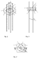
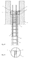
- thermal insulation element 1 is used for monolithic connection and load-bearing connection of a concrete pillar in the basement of a building to the overlying basement ceiling. It has a cuboid basic element 1 with a top side 2 and a bottom side 3, which serves in each case as bearing surfaces for the basement ceiling or the closure of the support supporting it. In the middle of the cuboid heat-insulating element 1 there is a central through-opening 4, which extends from the upper side 2 to the underside 3 of the heat-insulating element 1. The reinforcing element projects through four reinforcing rods 5.
- the underside 3 of the heat-insulating element 1 has a three-dimensional profiling in the form of a funnel-shaped recess 6 extending in the direction of the through-opening 4.
- a reinforcement arranged at right angles thereto, for example a reinforcing bar 7, is embedded, which surrounds the reinforcing bars 5 and gives the heat-insulating element additional stability.
- the thermal insulation element 1 consists of a lightweight concrete, which on the one hand has a high pressure stability, on the other hand, a good thermal insulation property. Compared to concrete with a thermal conductivity of about 1.6 W / (m ⁇ K) When using a suitable lightweight concrete material, the thermal conductivity is in the range of about 0.5 W / (m ⁇ K), which corresponds to an improvement of about 70%.
- the lightweight concrete used consists essentially of expanded clay, fine sands, preferably light sand, flow agents and stabilizers that prevent segregation by floating the grain and improve the processability.
- the compressive strength of the thermal insulation element is sufficiently high to enable the statically planned utilization of the underlying in situ concrete support, for example in accordance with compressive strength class C25 / 30.
- the compressive strength of the thermal insulation element even corresponds to at least 1.5 times the statically required value. This ensures that, even in the event of possible faulty surfaces on the connecting surface between the thermal insulation element and support safety reserves are available, so that the thermal insulation element remains statically stable even at points higher load.
- the reinforcing rods 5 can be embedded in the lightweight concrete material of the cuboid base body 1 in the manufacture of the heat-insulating element. Alternatively, it is possible for easier production of the thermal insulation element to install in the production of sleeves as a kind of lost circuit through which the reinforcing rods 5 are inserted therethrough after curing of the lightweight concrete element 1.
- the reinforcing bars 5 themselves are in the embodiment of a fiber composite material such as the proven reinforcing rod ComBAR® Schöck, which consists of oriented in the direction of force glass fibers and a resin matrix.
- a glass fiber reinforcing rod has an extremely low thermal conductivity, which is up to 100 times lower than with reinforcing steel, and is thus ideally suited for use in the thermal insulation element.
- rebars of conventional type made of stainless steel or structural steel can be used.
- reinforcing bars made of a fiber composite material can transmit very high tensile forces, but in contrast to that, significantly lower pressure forces can lead to the destruction of the reinforcing bars.
- sleeves Through the use of sleeves, a positive embedding of the reinforcing bars in the surrounding concrete, which is normally intended and almost indispensable for concrete reinforcements, is avoided. If there is now a compressive force load, for example, subsidence in the building, so the reinforcing rods can deform elastically in their sleeves until the pressure forces are completely removed by the pressure-stable insulating body 1, so that a harmful compressive load on the reinforcing bars is avoided.
- the reinforcement in the thermal insulation element is designed only as tensile reinforcement, since the connection between the support and the floor above it can be statically considered anyway as articulated connection.
- a static, stable and permanent connection or monolithic connection between support and floor ceiling is achieved with continuous reinforcement the static requirements.
- the arrangement of the reinforcing bars 5 relative to the Base of the body 1 is slightly outside the main diagonal selected. The reason for this is that with a support in which the reinforcing bars 5 of the thermal insulation element 1 are installed, the reinforcement of the support is already in the corners.
- the reinforcing bracket 7 is made of a stainless steel bent into a ring, which is welded at the joint.
- the reinforcing bracket 7 has a diameter of about 200 mm with a material thickness of 8 mm or 10 mm.
- the main body of the heat-insulating element 1 has an edge length of 250 ⁇ 250 mm in the exemplary embodiment.
- the height is 100 mm and thus corresponds to the usual strength of a subsequently applied thermal barrier coating.
- the passage opening runs, as especially in Fig. 3 can be seen, slightly conical in that the passage opening 4 tapers from an upper dimension of 70 mm to a lower dimension of 65 mm.
- the passage opening can be closed by means of a corresponding likewise slightly conical plug (not shown).
- Fig. 4 shows the heat-insulating element in a side view, wherein on the main body 1 additionally circumferential seals 8 are mounted.
- the seals 8 may for example be designed as rubber lips or conventional sealing bands. They serve to seal the body of the thermal insulation element 1 edge-sealing against a formwork for the support to be created underneath to prevent rising of concrete or air ingress.
- Fig. 5 shows the installation situation of the thermal insulation element with respect to a support 23.
- the cross section shown extends below the body of the heat-insulating element 1.
- the made of in-situ concrete support 23 has a reinforcement with four arranged in the corners of the support 23 vertical reinforcing bars 25 and a plurality of horizontally the reinforcing bars 25 extending approximately square executed reinforcing bracket 26.
- the reinforcing bars 5 of the thermal insulation element are each slightly offset next to one of the reinforcing bars 25 of the support 23.
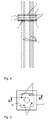
- Die in Fig. 5 drawn Section line BB corresponds to the cut of the in Fig. 7 shown longitudinal section through the column reinforcement.
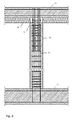
- FIG. 6 First, a longitudinal section through the support 23 and the connected building parts is shown.
- the support 23 is placed on a base plate 21 and carries a projecting ceiling 22 arranged above it. This may, for example, be the basement or basement ceiling of a building.
- Base plate 21, support 23 and floor slab 22 are statically connected.
- the pressure-transmitting heat-insulating element 1 is arranged, the reinforcing bars 5 are shed monolithic both in the support 23 and in the overlying floor slab 22.
- a thermal barrier coating 24 is applied, the thickness of which substantially corresponds at least to the height of the main body of the thermal insulation element 1.
- the thermal barrier coating 24 is applied from a highly insulating material, such as mineral insulation panels or wood wool multi-layer panels.
- Fig. 7 the reinforcement of the support 23 is shown together with the thermal insulation element 1 in a longitudinal section.
- the cutting guide corresponds to the section line BB Fig. 5 .
- the reinforcement of the support 23 consists of four arranged in the corners of the support vertical reinforcing bars 25, which may be made of structural steel with a rod diameter of 28 mm at a length of 2000 mm, and a plurality of horizontally around the reinforcing bars 25 encircling reinforcing bar with in about square floor plan.
- Above the column reinforcement is the thermal insulation element 1, the reinforcing rods 5 projecting downwards into the column reinforcement.
- the reinforcement content of the support 23 is about 3-4%. At a typical thermal conductivity of the structural steel of about 50 W / (m ⁇ K), it contributes about 1.6% of the total weight of 1.6 W / (m ⁇ K) to the overall thermal conductivity of the column.
- a typical thermal conductivity of the structural steel of about 50 W / (m ⁇ K)
- it contributes about 1.6% of the total weight of 1.6 W / (m ⁇ K) to the overall thermal conductivity of the column.
- the vibrating bottle of a concrete vibrator is passed through the passage opening 4 in the fresh in-situ concrete underneath in order to recompress it again.
- the heat-insulating element can be slightly lifted by the volume of the concrete displaced by the vibrating bottle.
- the circumferential seal 8 in this case prevents air between formwork 27 and thermal insulation element 1 can penetrate or the thermal insulation element 1 in the formwork 27 can tilt.
- FIG. 9 is the detail referred to as D detail around one of the seals 8 again drawn out enlarged.
- the passage opening 4 by means a conical plug (not shown) closed.
- the closure plug can be made of an insulating material such as polystyrene or similar. exist and serves to prevent the ingress of in-situ concrete in the through hole 4, when subsequently the floor slab 22 is created. In this way, any thermal bridges due to a concrete filling in the through hole 4 are avoided.
- the overlying floor slab 22 is created above the heat-insulating element 1 in a conventional manner.
- the passage opening 4 can also be used as a filling opening for filling the formwork for the support 23 with in-situ concrete.
- the thermal insulation element is inserted into the still empty formwork of the support 23 and optionally the reinforcing bars 5 connected to the column reinforcement.
- fresh concrete is filled through the passage opening 4 of the heat-insulating element in the formwork and then compressed by a through-opening 4 a vibrator bottle of an internal vibrator is introduced.
- a compression of the fresh concrete against the underside of the thermal insulation element takes place from above through the passage opening 4.
- the support 23 can also be made of self-compacting concrete, or the support can be compacted by an external vibrator. In the latter two cases, the passage opening 4 thus serves only as a filling opening.
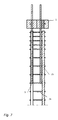
- FIG. 10 In addition to installation in the upper region of a support, installation in the foot region of a support is also conceivable. Such an arrangement is in an alternative embodiment in FIG. 10 shown.
- the support 23 is arranged here between the bottom plate 21 and the upper floor ceiling 22.
- an inventive thermal insulation element 1 is installed, projecting the reinforcing rods 5 of the bottom plate 21 into the upper region of the support 1 and there are connected to the reinforcement 25 of the support 1.
- a thermal barrier coating 24 'of insulation boards of known type is mounted in this case on the top of the bottom plate 21.
- the preparation can take place in such a way that the thermal insulation element 1 is connected before concreting the bottom plate 21 with its reinforcement 21 '.
- the bottom plate 21 is then cast from cast-in-place concrete, so that the concrete of rises down against the thermal insulation element 1.
- the in-situ concrete in turn can be compacted through the central passage opening 4 with a vibrating tool.
- the reinforcement 25 of the support is created and connected to the reinforcing bars 5 of the thermal insulation element.
- Around the thermal insulation element 1 around the formwork 27 is then constructed for the support 23 and then poured the support 23 in a conventional manner from in-situ concrete and compacted.
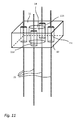
- a further embodiment of a heat-insulating element is shown.
- the base body 10 of the thermal insulation element shown here is not made of lightweight concrete but of a non-compressive heat insulating material such as foam glass or polystyrene foam.
- the individual printing elements 11a to 11d are made of a high-strength concrete in order to be able to remove the ballast through the overlying building part 22.
- Reinforcing bars 15 are cast into the individual pressure elements 11a to 11d and protrude in the vertical direction over the top 12 and the bottom 13 of the heat-insulating element 15 addition.
- a through hole 14 is provided, which serves as a filling and / or compression opening.
- the installation of the thermal insulation element 10 takes place as in the previous embodiment.
- the heat-insulating property is achieved in this embodiment mainly by the areal reduction of thermal bridges to the few individual pressure elements 11a to 11d.
- the present invention is not limited to the form and number of individual printing elements shown in the embodiment. Rather, the provided within the insulating body 10 portion of pressure-transmitting material can be performed in a variety of other geometries, such as in the form of a pressure-transmitting cylindrical ring.
- the reinforcing rods 15 need not necessarily be guided by the arranged in the insulating body 10 pressure-transmitting areas 11 a to 11 d, but can also be plugged separately thereof by the non-compressive force transmitting areas of the thermal insulation element 10.
- thermal insulation element itself may be adapted in its dimensions to the underlying and / or overlying component.
- thermal insulation elements can be adapted to the typical cross sections of supports with a round, square or rectangular layout. Typical dimensions of round columns are diameters of 24 and 30 cm, and of rectangular bases 25 x 25 cm and 30 x 30 cm. Thermal insulation elements with such a geometry can also be combined as desired to larger columns or support walls.
- the heat insulation elements described herein are particularly suitable for use with pendulum supports and wall supports with low clamping moments.
- the use of supporting outer walls is possible by the heat insulation elements are installed at a suitable distance from each other and any remaining gaps between the individual thermal insulation elements are filled with non-supporting insulation material.
- the geometric design of the profiled underside of the thermal insulation element can be realized in many other ways besides the conical shape shown here, for example in a stepped shape, a radial toothing, an annular bead and much more.
- openings may also be provided for subsequent encapsulation of possibly remaining cavities between the thermal-insulating element and the concrete surface located thereunder.
- Such openings can be closed by means of blind plugs and opened as needed to subsequently fill any remaining cavity by means of a potting compound such as a grout or a synthetic resin composition and thus produce a secure static connection, even if in an individual case a faulty design in the preparation of the support or the installation of the thermal insulation element had led to a poor connection.
- indicators may be provided on the thermal insulation element, which can be pushed up in the manner of a float and indicate here, that the heat-insulating element has contact with the underlying in-situ concrete on its underside.
- thermal insulation element When installing the thermal insulation element in the already compacted, fresh concrete of the underlying support, the subsequent recompression and when pulling out of the compaction tool from the passage opening of the thermal element, it may optionally be advantageous if a defined pressure force is exerted on the thermal insulation element.
- rod-shaped reinforcing means for connecting the heat-insulating element to the above and below building parts can be used, for example threaded rods, dowels or the like, as explained above, the connection between a support and a floor above it static as articulated connection can be considered and the reinforcement therefore preferably has to fulfill a constructive function at this point.
Landscapes
- Engineering & Computer Science (AREA)
- Architecture (AREA)
- Physics & Mathematics (AREA)
- Civil Engineering (AREA)
- Structural Engineering (AREA)
- Electromagnetism (AREA)
- Acoustics & Sound (AREA)
- Building Environments (AREA)
Abstract
Bei einem Wärmedämmelement, welches zumindest teilweise aus einem druckkraftübertragenden Werkstoff besteht und eine obere und eine untere Auflagefläche zum vertikalen Anschluss an die aus Beton zu erstellenden Gebäudeteile aufweist, ist vorgesehen, dass das Wärmedämmelement zumindest eine sich von der oberen bis zur unteren Auflagefläche erstreckende Durchgangsöffnung aufweist, welche zum Durchführen eines Verdichtungsgeräts für Frischbeton ausgebildet ist.In a thermal insulation element which at least partially consists of a pressure-transmitting material and has an upper and a lower support surface for vertical connection to the building parts to be made of concrete, it is provided that the heat-insulating element has at least one passage opening extending from the upper to the lower support surface , which is designed for performing a compacting device for fresh concrete.
Description
Die vorliegende Erfindung betrifft ein Wärmedämmelement zur Wärmeentkopplung zwischen aus Beton zu erstellenden, tragenden Gebäudeteilen, vorzugsweise zwischen einem vertikalen Gebäudeteil, insbesondere einer Schütze, und einem darüber oder darunter liegenden, horizontalen Gebäudeteil, insbesondere einer Geschossdecke oder einer Bodenplatte.The present invention relates to a thermal insulation element for heat decoupling between building concrete parts to be created from concrete, preferably between a vertical part of the building, in particular a Sagittarius, and an overlying or underlying horizontal building part, in particular a floor slab or a floor slab.
Im Hochbau werden tragende Gebäudeteile häufig aus mit einer Bewehrung versehenen Betonkonstruktionen erstellt. Aus energetischen Gründen werden solche Gebäudeteile in der Regel mit einer von außen angebrachten Wärmedämmung versehen. Insbesondere die Geschossdecke zwischen Tiefgeschoss, wie beispielsweise Keller oder Tiefgarage, und Erdgeschoss wird häufig auf der Tiefgeschossseite mit einer deckenseitig angebrachten Wärmedämmung ausgerüstet. Hierbei ergibt sich die Schwierigkeit, dass die tragenden Gebäudeteile, auf denen das Gebäude ruht, wie etwa Stützen und Außenwände, in lastabtragender Weise mit den darüber befindlichen Gebäudeteilen, insbesondere der Geschossdecke, verbunden sein müssen. Dies wird in der Regel dadurch erreicht, dass die Geschossdecke bei durchgehender Bewehrung monolithisch mit den tragenden Stützen und Außenwänden verbunden wird. Hierbei entstehen jedoch Wärmebrücken, die sich nur schlecht durch eine nachträglich von außen angebrachte Wärmedämmung beseitigen lassen. In Tiefgaragen wird beispielsweise häufig der obere, zur Geschossdecke weisende Abschnitt der tragenden Betonstützen ebenfalls mit einer Wärmedämmung ummantelt. Dies ist nicht nur aufwendig und optisch wenig ansprechend, sondern führt auch zu unbefriedigenden bauphysikalischen Ergebnissen und vermindert zudem den in der Tiefgarage verfügbaren Parkraum.In building construction, load-bearing parts of buildings are often made of reinforced concrete structures. For energy reasons, such building parts are usually provided with an externally mounted thermal insulation. In particular, the floor slab between basement, such as basement or underground car park, and ground floor is often equipped on the basement side with a heat insulation applied to the ceiling. This results in the difficulty that the load-bearing parts of the building, on which the building rests, such as columns and outer walls, in load-bearing manner with the overlying building parts, in particular the floor ceiling must be connected. This is usually achieved by connecting the floor slab monolithically to the supporting pillars and outer walls with continuous reinforcement. However, this creates thermal bridges, which can be eliminated only badly by a later externally mounted thermal insulation. In underground garages, for example, often the upper, facing the floor ceiling section of the load-bearing concrete columns are also covered with a thermal insulation. This is not only complex and visually unappealing, but also leads to unsatisfactory building physics results and also reduces the parking space available in the underground car park.
Aus der Schrift
Aus der Schrift
Beim Einbau eines solchen vorgefertigten Anschlusselements müssen die Bewehrungselemente beim Betonieren der angrenzenden Gebäudeteile mit vergossen werden. Zu diesem Zweck muss das Anschlusselement in eine geschlossene Schalung für das darunter liegende Gebäudeteil eingebaut werden und es muss von unten gegen die bestehende, nicht zugängliche und nicht sichtbare Unterseite des Anschlusselements betoniert werden. Insbesondere bei Stützen und Außenwänden, bei denen es sich um tragende Bauwerksteile handelt, kann eine mangelhaft Ausführung beim Erstellen der Gebäudeteile insbesondere an der Verbindungsstelle zu dem Anschlusselement später zu gravierenden statischen Problemen am Gebäude führen. Hinzu kommt, dass eine Kontrolle und Überwachung der Ausführung kaum möglich ist. Insbesondere ist eine Sichtkontrolle vor und während des Betonierens wegen der Einbausituation in die Schalung nicht gegeben. Am fertigen Gebäudeteil ist eine Prüfung ebenfalls kaum mehr möglich, da die Verbindungsfläche zwischen Gebäudeteil und Anschlusselement nicht zugänglich ist.When installing such a prefabricated connection element, the reinforcing elements must be potted when concreting the adjacent building parts. For this purpose, the connection element must be installed in a closed formwork for the underlying building part and it must be concreted from below against the existing, inaccessible and invisible underside of the connection element. In particular, in columns and exterior walls, which are supporting structural parts, a poor execution when creating the building parts, especially at the junction with the connection element later lead to serious structural problems on the building. In addition, a control and monitoring of the execution is hardly possible. In particular, a visual inspection before and during concreting because of the installation situation in the formwork is not given. On the finished part of a building examination is also hardly possible because the connection surface between the building part and connection element is not accessible.
Der Erfindung liegt daher die Aufgabe zugrunde, ein Wärmedämmelement anzugeben, welches einen zuverlässigen Einbau an einer vertikal lastabtragenden Verbindungsstelle zwischen zwei aus Beton zu erstellenden Gebäudeteilen ermöglicht.The invention is therefore based on the object to provide a thermal insulation element, which allows reliable installation on a vertical load-bearing connection point between two building parts to be created from concrete.
Die Aufgabe wird gelöst durch die Merkmale des Anspruchs 1. Vorteilhafte Ausgestaltungen sind den anhängigen Ansprüchen zu entnehmen. Darüber hinaus betrifft die Erfindung ein Verfahren zum Einbau eines entsprechenden Wärmedämmelements.The object is solved by the features of
Bei einem erfindungsgemäßen Wärmedämmelement, welches zumindest teilweise aus einem druckkraftübertragenden Werkstoff besteht und eine obere und eine untere Auflagefläche zum vertikalen Anschluss an die aus Beton zu erstellenden Gebäudeteile aufweist, wird die Aufgabe dadurch gelöst, dass das Wärmedämmelement zumindest eine sich von der oberen bis zur unteren Auflagefläche erstreckende Durchgangsöffnung aufweist, welche zum Durchführen eines Verdichtungsgeräts ausgebildet ist. Die Durchgangsöffnung dient somit als Eintauchstelle für einen Innenrüttler. Vorzugsweise ist die Durchgangsöffnung in dem Wärmedämmelement in etwa mittig angeordnet.In a thermal insulation element according to the invention, which consists at least partially of a pressure-transmitting material and has an upper and a lower support surface for vertical connection to the building parts to be made of concrete, the object is achieved in that the thermal insulation element at least one from the top to the bottom Supporting surface extending through opening, which is designed for performing a compacting device. The passage opening thus serves as a dipping point for an internal vibrator. Preferably, the passage opening in the thermal insulation element is arranged approximately centrally.
Der vorliegenden Erfindung liegt die Erkenntnis zugrunde, dass beim Einbau und anschließendem Betonieren gegen die Unterseite des Wärmedämmelements eine unzureichende und undefinierte Verdichtung des Ortbeton unterhalb des Wärmedämmelements auftreten kann, die zudem stark von der Zusammensetzung des verwendeten Ortbetons abhängt. Nach Erkenntnis der Erfindung können an der Unterseite des Wärmedämmelements beim Abbinden des Ortbetons zwei Prozesse dazu führen, dass die lastabtragende Anbindung des Wärmedämmelements an das darunter liegende Gebäudeteil mangelhaft ist. Einerseits können aufsteigende Luftblasen, sogenannte Verdichtungsporen, an der Unterseite des Wärmedämmelements zu Lunkerbildung führen und so für eine statisch unzureichende Anbindung sorgen. Ein noch kritischerer Prozess stellt eine Sedimentation im noch nicht abgebundenen Ortbeton dar, bei dem schwerere Zuschlagstoffe langsam absinken und an der Betonoberfläche Wasser bzw. Zementleim abgesondert wird. Nach dem Abbinden und Austrocknen des Betonteils können in diesem Fall großflächige Hohlstellen zwischen dem Wärmedämmelement und dem darunter befindlichen Betonteil verbleiben, die von außen nicht sichtbar sind.The present invention is based on the finding that during installation and subsequent concreting against the underside of the thermal insulation element an inadequate and undefined compaction of the in-situ concrete below the thermal insulation element can occur, which also depends strongly on the composition of the used concrete in situ. According to the invention, two processes can lead to the underside of the thermal insulation element when setting the in-situ concrete that the load-bearing connection of the thermal insulation element to the underlying building part is deficient. On the one hand rising air bubbles, so-called compression pores, on the underside of the heat-insulating element lead to voids formation and thus provide a statically insufficient connection. An even more critical process is sedimentation in as-cast-in-situ concrete, in which heavier aggregates slowly sink and water or cement paste is separated on the concrete surface. After setting and drying of the concrete part can in this case large voids remain between the thermal insulation element and the underlying concrete part, which are not visible from the outside.
Um dies zu vermeiden wird in dem erfindungsgemäßen Wärmedämmelement eine Durchgangsöffnung vorgesehen, durch welche ein Verdichtungsgerät wie etwa die Rüttelflasche eines Betonrüttlers hindurchgeführt werden kann, um nach dem Einbau des Wärmedämmelementes den darunter befindlichen Ortbeton zu verdichten bzw. nachzuverdichten. Durch diese Verdichtung bzw. Nachverdichtung können die beschriebenen Probleme vermieden und eine zuverlässige Anbindung des Wärmedämmelementes an das darunter befindliche Gebäudeteil erreicht werden.To avoid this, a passage opening is provided in the thermal insulation element according to the invention, through which a compacting device such as the vibrating bottle of a concrete vibrator can be passed after the installation of the thermal insulation element to compact or recompress the underlying concrete located underneath. By this compression or densification of the described problems can be avoided and a reliable connection of the thermal insulation element to the underlying building part can be achieved.
Bei einer bevorzugten Ausführungsform ist das Wärmedämmelement zumindest teilweise aus einem druckkraftübertragenden und wärmedämmenden Werkstoff hergestellt. Vorzugsweise kann es sich bei diesem Werkstoff um einen Leichtbeton handeln. Aus Leichtbeton lassen sich unter Fabrikbedingungen hochdruckfeste Formelemente mit niedriger spezifischer Wärmeleitfähigkeit herstellen. Je nach statischer Anforderung kann ein solches Leichtbetonformteil neben der erfindungsgemäßen Durchgangsöffnung weitere Hohlkammern oder eingeschlossene Isolierelemente umfassen.In a preferred embodiment, the thermal insulation element is at least partially made of a pressure-transmitting and heat-insulating material. Preferably, this material may be a lightweight concrete. Made of lightweight concrete can be manufactured under factory conditions high pressure resistant mold elements with low specific thermal conductivity. Depending on the static requirement, such a lightweight concrete molded part can comprise, in addition to the passage opening according to the invention, further hollow chambers or enclosed insulating elements.
Unter Leichtbeton ist nach dem geltenden Regelwerk ein Beton mit einer trockenen Rohdichte von maximal 2000 kg/m3 definiert. Die geringe Dichte im Vergleich zu Normalbeton wird durch entsprechende Herstellverfahren und unterschiedliche Leichtbetonkörnungen wie etwa Körnungen mit Kornporosität wie Blähton erreicht. Leichtbeton besitzt je nach Zusammensetzung eine Wärmeleitfähigkeit zwischen 0,2 und 1,6 W/(m · K).According to the applicable regulations, lightweight concrete is defined as a concrete with a dry bulk density of a maximum of 2000 kg / m 3 . The low density compared to normal concrete is achieved by appropriate manufacturing process and different lightweight concrete grains such as grains with grain porosity such as expanded clay. Lightweight concrete has, depending on the composition, a thermal conductivity between 0.2 and 1.6 W / (m · K).
Als weiterer Vorteil ergibt sich, dass bei gleicher Festigkeitsklasse der E-Modul von Leichtbeton nur etwa 30 bis 70 % der Werte von Normalbeton beträgt. Daher sind die elastischen Verformungen bei gleicher Beanspruchung (Spannung) im Mittel 1,5- bis 3-mal so groß. Aus diesem Grund wirkt ein Wärmedämmelement aus Leichtbeton gleichzeitig als Spannungs-Dämpfungselement und ist in der Lage, kleinere Setzungen und elastische Verformungen des darüber liegenden Gebäudeteils auszugleichen und eine gleichmäßigere Verteilung und Krafteinleitung von außerzentrischen Auflagekräften auf bzw. in das darunterliegende Gebäudeteil, insbesondere eine Stütze, sicherzustellen.Another advantage is that with the same strength class, the modulus of elasticity of lightweight concrete is only about 30 to 70% of the value of normal concrete. Therefore, the elastic deformations at the same stress (stress) on average 1.5 to 3 times as large. For this reason, a thermal insulation element made of lightweight concrete acts simultaneously as a stress-damping element and is able to compensate for smaller settlements and elastic deformations of the overlying building part and a more even distribution and force of eccentric bearing forces on or in the underlying building part, in particular a support, sure.
Das wesentlich geringere E-Modul des verwendeten Leichtbetons wirkt sich hierbei besonders günstig bei Last-Ausmitten und Auflagerverdrehungen aus, die erhöhte Kantenpressungen zur Folge haben. Das Wärmedämmelement wirkt aufgrund seiner elastischen Eigenschaften sozusagen als "Zentrierelement". Im Gegensatz dazu ist die Stauchung bei zentrischer Belastung von untergeordneter Bedeutung.The significantly lower modulus of elasticity of the lightweight concrete used has a particularly favorable effect on load eccentricities and bearing misalignments, which result in increased edge pressure. The thermal insulation element acts as a kind of "centering element" due to its elastic properties. in the In contrast, compression under centric loading is of secondary importance.
Das typische E-Modul von Normalbeton, wie er für eine Stütze verwendet wird, beträgt etwa Ecm≈30.000 bis 40.000 N/mm2. Das E-Modul des im Rahmen der Erfindung bevorzugten Leichtbetons beträgt dem gegenüber zwischen etwa 9.000 und 22.000 N/mm2, vorzugsweise 12.000 und 16.000 N/mm2, höchstvorzugsweise etwa 14.000 N/mm2.The typical modulus of elasticity of normal concrete, as used for a column, is about E cm ≈30,000 to 40,000 N / mm 2 . The modulus of elasticity of the lightweight concrete preferred in the invention is on the other hand between about 9,000 and 22,000 N / mm 2 , preferably 12,000 and 16,000 N / mm 2 , most preferably about 14,000 N / mm 2 .
Alternativ kann das Wärmedämmelement auch aus einem wärmedämmenden aber nicht druckkraftübertragenden Isolierkörper, beispielsweise aus extrudiertem Polystyrol mit einem oder mehreren darin eingebetteten Druckkörpern bestehen. Solche Druckkörper können aus hochfestem Beton hergestellt werden, wobei eine Reduzierung der Wärmeleitfähigkeit des Wärmedämmelements in diesem Falle durch eine entsprechend kleine Grundfläche der Druckelemente erreicht wird. Auch in diesem Fall ist wesentlich, dass beim Einbau des Wärmedämmelements eine Nachverdichtung des darunter betonierten Gebäudeteils erfolgt, indem ein entsprechendes Rüttelwerkzeug durch die im Wärmedämmelement vorgesehene Durchgangsöffnung in den darunterliegenden Ortbeton des angrenzenden frisch betonierten Gebäudeteils eingeführt wird.Alternatively, the thermal insulation element may also consist of a heat-insulating but not pressure-transmitting insulating body, for example made of extruded polystyrene with one or more pressure bodies embedded therein. Such pressure body can be made of high-strength concrete, with a reduction in the thermal conductivity of the thermal insulation element is achieved in this case by a correspondingly small footprint of the printing elements. Also in this case, it is essential that during installation of the thermal insulation element a re-compaction of the concreted under building part takes place by a corresponding shaking tool is introduced through the provided in the thermal insulation element passage opening in the underlying in-situ concrete of the adjacent freshly concreted building part.
Gegenüber einem massiven oder in Hohlblockbauweise gefertigten Wärmedämmelement aus Leichtbeton hat die letztgenannte Variante aufgrund der deutlich kleineren Auflagefläche allerdings den Nachteil, dass bereits kleinere Schwachstellen in der Anbindung an das darunterliegende Gebäudeteil aufgrund von Lunkerbildung oder Sedimentation deutlich stärkere Auswirkung auf die statische Stabilität der Konstruktion haben. Schlimmstenfalls kann es zu einer lokalen Überlastung und damit einem Versagen einzelner Druckelemente des Wärmedämmelements kommen. Diese Gefahr ist aufgrund der wesentlich größeren Auflagefläche bei einem Wärmedämmelement aus einem druckkraftübertragenden Werkstoff wie Leichtbeton wesentlich geringer.Compared to a solid or manufactured in hollow block construction thermal insulation element made of lightweight concrete, the latter variant due to the much smaller surface area, however, has the disadvantage that even minor vulnerabilities in the connection to the underlying building part due to cavitation or sedimentation have significantly stronger impact on the static stability of the construction. In the worst case, it can lead to a local overload and thus a failure of individual pressure elements of the thermal insulation element. This risk is much lower due to the much larger contact surface with a thermal insulation element of a pressure-transmitting material such as lightweight concrete.
Ein weiterer Vorteil der vorliegenden Erfindung ergibt sich, wenn die untere Auflagefläche des Wärmedämmelements eine Oberfläche mit dreidimensionalem Profil aufweist. Durch geeignete Profilierung der Oberfläche lassen sich Defekte in der Verbindung zwischen Wärmedämmelement und dem darunter liegenden frisch betonierten Gebäudeteil weiter vermindern. So kann die Oberfläche beispielsweise Erhöhungen und Vertiefungen aufweisen sowie geneigte Flächen, Furchen, oder ähnliches, so dass im Falle auftretender Sedimentation das sich absetzende Oberflächenwasser in unkritische Bereiche ablaufen bzw. sich dort absetzen kann, während in für die statische Anbindung kritischen Bereichen des Wärmedämmelements eine innige Verbindung zum Frischbeton des darunterliegenden Gebäudeteils entsteht.Another advantage of the present invention results when the lower bearing surface of the heat-insulating element has a surface with a three-dimensional profile. By suitable profiling of the surface, defects in the connection between the thermal insulation element and the underlying further reduce the newly concreted part of the building. Thus, for example, the surface may have elevations and depressions, as well as inclined surfaces, furrows, or the like, so that in the event of sedimentation, the settling surface water can run into noncritical regions or settle there, while in areas of the thermal insulation element that are critical for the static connection intimate connection to the fresh concrete of the underlying building part is created.
Als besonders bevorzugt wird in diesem Zusammenhang eine Ausführungsform angesehen, bei der die untere Auflagefläche eine trichterförmig in Richtung der Durchgangsöffnung geneigte oder gewölbte Oberfläche aufweist. Hierdurch wird erreicht, dass im Falle auftretender Sedimentation das sich absetzende Oberflächenwasser in Richtung der Durchgangsöffnung verdrängt wird bzw. sich nur in diesem Bereich bildet, der zur Statik der Konstruktion ohnehin nicht beiträgt.Particularly preferred in this context is an embodiment in which the lower bearing surface has a funnel-shaped inclined or curved surface in the direction of the passage opening. This ensures that in the event of sedimentation, the settling surface water is displaced in the direction of the passage opening or forms only in this area, which does not contribute to the static of the construction anyway.
Bei einer bevorzugten Ausführungsform der vorliegenden Erfindung sind außerdem ein oder mehrere stabförmige Bewehrungselemente vorgesehen, die das Wärmedämmelement durchdringen und sich im Wesentlichen vertikal über die obere und untere Auflagefläche hinaus erstrecken. Mit solchen Bewehrungselementen kann das Wärmedämmelement mit den angrenzenden Gebäudeteilen verbunden und gegebenenfalls an deren Bewehrung angeschlossen werden. Somit wird eine monolithische Verbindung der Gebäudeteile erreicht, auch wenn aufgrund statischer Anforderungen die Verbindung lediglich als Betongelenk betrachtet und die Bewehrungselemente somit eine eher konstruktive Funktion ohne größere Bedeutung für die Gebäudestatik erfüllen.In a preferred embodiment of the present invention, one or more rod-shaped reinforcing elements are also provided, which penetrate the heat-insulating element and extend substantially vertically beyond the upper and lower bearing surfaces. With such reinforcing elements, the thermal insulation element can be connected to the adjacent building parts and optionally connected to the reinforcement. Thus, a monolithic connection of the building parts is achieved, even if considered due to static requirements, the compound only as a concrete joint and the reinforcing elements thus fulfill a more constructive function without major importance for building statics.
Vorzugsweise können die Bewehrungselemente als Bewehrungsstäbe ausgebildet werden, die vorwiegend zur Übertragung von Zugkräften dienen. Häufig werden Bewehrungselemente, die eine Wärmedämmung durchqueren müssen, aus bauphysikalischen Gründen aus Edelstahl bzw. nichtrostendem Stahl gefertigt. Im Rahmen der vorliegenden Erfindung können aus Gründen der besseren thermischen Isolierung die Bewehrungselemente vorzugsweise aus einem Faserverbundwerkstoff wie etwa glasfaserverstärkten Kunststoff hergestellt werden.Preferably, the reinforcing elements can be formed as reinforcing bars, which serve primarily for the transmission of tensile forces. Often reinforcing elements, which must traverse a thermal insulation, made of structural-physical reasons of stainless steel or stainless steel. In the context of the present invention, for reasons of better thermal insulation, the reinforcing elements can preferably be made of a fiber composite material, such as glass fiber reinforced plastic.
Des Weiteren erweist es sich als vorteilhaft, wenn im Inneren des druckkraftübertragenden Werkstoffs in dem Wärmedämmelement ein Bewehrungsbügel angeordnet wird. Ein solcher Bewehrungsbügel in Form eines in sich geschlossenen Bewehrungsringes mit beispielsweise kreisrunder oder abgerundet mehreckiger Grundfläche, der in einer bezüglich der Auflageflächen im Wesentlichen parallelen Ebene angeordnet wird, kann die Druckkraftbeständigkeit des Wärmedämmelements weiter steigern, indem dieser die Querdehnung des Wärmedämmelements unter Druck minimiert.Furthermore, it proves to be advantageous if a reinforcing bracket is arranged in the interior of the pressure-transmitting material in the thermal insulation element. Such a reinforcing bar in the form of a self-contained reinforcing ring with, for example, circular or rounded polygonal base, which is arranged in a plane substantially parallel to the support surfaces, can further increase the compressive strength of the heat-insulating element by minimizing the transverse strain of the heat-insulating element under pressure.
Ein weiterer vorteilhafter Aspekt der vorliegenden Erfindung ergibt sich, wenn an dem Wärmedämmelement mindestens eine um dessen vertikale Begrenzungsflächen umlaufende Dichtung vorgesehen wird, welche einen dichten Einbau des Wärmedämmelements in eine Schalung für das darunter liegende Gebäudeteil gewährleistet. Einerseits wird durch eine solche Dichtung verhindert, dass beim Einsetzen des Wärmedämmelements oder Betonieren des darunterliegenden Gebäudeteils Frischbeton zwischen Schalung und Wärmedämmelement eindringen und aufsteigen kann. Andererseits verhindert eine solche Dichtung das Eindringen von Luft zwischen Schalung und Wärmedämmelement, wenn nach erfolgtem Verdichten das Rüttelwerkzeug aus der Durchgangsöffnung des Wärmedämmelements herausgezogen wird und das Wärmedämmelement um das zuvor vom Rüttelwerkzeug verdrängte Volumen innerhalb der Schalung des darunterliegenden Gebäudeteils absinkt.A further advantageous aspect of the present invention results if at least one seal surrounding the vertical boundary surfaces of the heat-insulating element is provided, which ensures a tight installation of the heat-insulating element into a formwork for the underlying building part. On the one hand is prevented by such a seal that when inserting the thermal insulation element or concreting the underlying building part fresh concrete penetrate between formwork and thermal insulation element and can rise. On the other hand, such a seal prevents the ingress of air between the formwork and the thermal insulation element, after the compacting the vibrating tool is pulled out of the passage opening of the heat-insulating element and the heat-insulating element falls to the volume previously displaced by the vibrating tool within the formwork of the underlying building part.
Neben der Durchgangsöffnung für das Rüttelwerkzeug können in dem Wärmedämmelement weitere Vergussöffnungen vorgesehen sein, über die erforderlichenfalls nach Aushärten des Betons zusätzlich Vergussmasse, wie etwa Vergussmörtel eingefüllt werden kann, um etwaige noch bestehende Hohlräume zwischen dem darunterliegenden Gebäudeteil und dem Wärmedämmelement auszufüllen. Vorzugsweise sind die betreffenden Vergussöffnungen mittels herausnehmbarer Blindstopfen verschlossen, so dass diese beim Einbau des Wärmedämmelementes nicht von Ortbeton verstopft werden können.In addition to the passage opening for the vibrating tool further Vergussöffnungen can be provided in the thermal insulation element, on the required case after hardening of the concrete additional potting compound, such as grout can be filled to fill any remaining voids between the underlying building part and the thermal insulation element. Preferably, the respective potting holes are closed by means of removable blind plugs, so that they can not be clogged with in situ concrete during installation of the thermal insulation element.
Weiterhin ist im Rahmen der vorliegenden Erfindung bevorzugt, dass ein Verschlussstopfen vorgesehen wird, mit dem die Durchgangsöffnung nachträglich verschlossen werden kann. Hierbei ist weiter bevorzugt, dass der Verschlussstopfen aus einem wärmedämmenden, aber nichttragenden Material besteht, wie beispielsweise extrudiertem Polystyrol. Außerdem kann ein solcher Verschlussstopfen konisch geformt sein, so dass er dichtend in die, vorzugsweise ebenfalls konisch nach unten hin zulaufende Durchgangsöffnung eingesetzt werden kann. Somit ist sichergestellt, dass nach dem Einbau des Wärmedämmelementes keine Wärmebrücke durch die Durchgangsöffnung bestehen bleibt, beispielsweise aufgrund in der Durchgangsöffnung eintretenden Ortbetons beim Betonieren der darüber liegenden Geschossdecke.Furthermore, in the context of the present invention, it is preferred that a sealing plug is provided, with which the passage opening can be subsequently closed. In this case, it is further preferred that the sealing plug consists of a heat-insulating, but non-bearing material, such as extruded polystyrene. In addition, such a closure plug may be conically shaped, so that it can be sealingly inserted into the, preferably also conically downwardly tapered passage opening. Thus, it is ensured that after installation of the thermal insulation element no thermal bridge remains through the through hole, for example, due to entering the through hole in-situ concrete when concreting the overlying floor slab.
Zusätzlich können in dem Wärmedämmelement ein oder mehrere Indikatoren vorgesehen werden, die einen ausreichenden Kontakt der unteren Anlagefläche mit dem Frischbeton des darunter zu erstellenden Gebäudeteils anzeigen. solche Indikatoren können beispielsweise in der Art eines Schwimmers ausgebildet sein. Wenn somit bei ausreichendem Kontakt die Indikatoren an der oberen Auflagefläche des Wärmedämmelements sichtbar werden ist sichergestellt, dass ausreichend Kontakt zu der darunterliegenden Betonfläche besteht.In addition, one or more indicators can be provided in the thermal insulation element, which indicate sufficient contact of the lower contact surface with the fresh concrete of the building part to be created below. Such indicators may be designed, for example, in the manner of a float. Thus, if the indicators are visible on the upper bearing surface of the thermal insulation element with sufficient contact is ensured that there is sufficient contact with the underlying concrete surface.
Um ein Durchführen eines Rüttelwerkzeuges, beispielsweise der Rüttelflasche eines Betonrüttlers, zu ermöglichen, besitzt die Durchgangsöffnung ein Öffnungsmaß dass groß genug ist, um das Durchführen baustellenüblicher Rüttelflaschen zu ermöglichen, insbesondere von mindestens 50 mm, vorzugsweise zwischen 60 und 80 mm.In order to make it possible to carry out a vibrating tool, for example the vibrator bottle of a concrete vibrator, the through-opening has an opening dimension which is large enough to allow the execution of shaking bottles customary in the field, in particular of at least 50 mm, preferably between 60 and 80 mm.
Die Erfindung betrifft darüber hinaus ein Verfahren zum Einbau eines solchen Wärmedämmelementes zwischen zwei aus Beton zu erstellenden, tragenden Gebäudeteilen, vorzugsweise zwischen einem vertikalen Gebäudeteil, insbesondere einer Stütze, und einem darüber oder darunter liegenden horizontalen Gebäudeteil, insbesondere einer Geschossdecke oder einer Bodenplatte. Hierbei wird zunächst eine Schalung für das untere Gebäudeteil erstellt und das untere Gebäudeteil betoniert, indem Ortbeton in die Schalung eingefüllt und verdichtet wird. Dann wird in einem zweiten Schritt das Wärmedämmelement in die Schalung für das untere Gebäudeteil eingesetzt. Hierbei werden die gegebenenfalls nach unten über das Wärmedämmelement hinausragenden Bewehrungselemente in den frischen Ortbeton des unteren Gebäudeteils eingedrückt. Erfindungsgemäß erfolgt in einem anschließenden Schritt ein Nachverdichten des Betons mittels eines Verdichtungsgerätes, welches durch die Durchgangsöffnung in dem Wärmedämmelement hindurch geführt wird. Vorzugsweise kann die Durchgangsöffnung anschließend mittels eines Verschlussstopfens verschlossen werden. Danach kann oberhalb des Wärmedämmelements in an sich üblicher Weise das obere Gebäudeteil, zum Beispiel eine Geschossdecke erstellt werden.The invention further relates to a method for installing such a thermal insulation element between two bearing concrete parts to be created from concrete, preferably between a vertical part of the building, in particular a support, and an overlying horizontal or horizontal building part, in particular a floor slab or a floor slab. Here, a formwork for the lower part of the building is first created and concreted the lower part of the building by in-situ concrete is poured into the formwork and compacted. Then, in a second step, the thermal insulation element is inserted into the formwork for the lower part of the building. Here, if necessary, the downwardly projecting beyond the thermal insulation element reinforcing elements are pressed into the fresh in-situ concrete of the lower part of the building. According to the invention, in a subsequent step, the concrete is recompressed by means of a compacting device, which is guided through the passage opening in the thermal insulation element. Preferably, the Passage opening are then closed by means of a sealing plug. Thereafter, above the thermal insulation element in a conventional manner, the upper part of the building, for example a floor ceiling can be created.
Durch das Nachverdichten des noch frischen Ortbetons des unteren Gebäudeteils nach Einsetzen des Wärmedämmelements wird sichergestellt, dass zu dessen unterer Anlagefläche inniger Kontakt besteht und Hohlräume aufgrund von Lunkerbildung und Sedimentation zwischen Wärmedämmelement und dem darunter befindlichen Gebäudeteil vermieden werden.By re-densifying the still fresh in-situ concrete of the lower part of the building after insertion of the thermal insulation element ensures that there is intimate contact with its lower contact surface and cavities are avoided due to cavitation and sedimentation between the thermal insulation element and the underlying building part.
Bei einem alternativen Einbauverfahren kann das Wärmedämmelement auch vor dem Verfüllen der Schalung mit Ortbeton eingebaut werden. In diesem Fall kann die Durchgangsöffnung zunächst als Einfüllöffnung für den Ortbeton verwendet werden. Anschließend erfolgt eine Verdichtung des eingefüllten Betons, indem durch die Durchgangsöffnung das Rüttelwerkzeug in den frischen Ortbeton eingeführt wird.In an alternative installation method, the thermal insulation element can also be installed before filling the formwork with in-situ concrete. In this case, the passage opening can initially be used as a filling opening for the in-situ concrete. Subsequently, a compression of the filled concrete is carried out by the vibrating tool is introduced into the fresh in-situ concrete through the passage opening.
Weitere Merkmale, Vorteile und Eigenschaften der vorliegenden Erfindung werden im Folgenden anhand der Figuren und anhand von Ausführungsbeispielen erläutert. Dabei zeigt:
- Fig. 1
- eine isometrische Ansicht eines erfindungsgemäßen Wärmedämmelements aus einem druckkraftübertragenden Werkstoff, insbesondere Leichtbeton
- Fig. 2
- eine Draufsicht auf das Wärmedämmelement aus
Fig. 1 , - Fig. 3
- einen vertikalen Schnitt durch das Wärmedämmelement entlang der Schnittlinie C-C aus
Fig. 2 , - Fig. 4
- eine Weiterbildung des Wärmedämmelements aus
Fig. 1 in einer Seitenansicht, - Fig. 5
- einen Querschnitt einer Stütze eines Gebäudes, die mit einem Wärmedämmelement ausgestattet ist,
- Fig. 6
- einen Schnitt durch die
Stütze aus Figur 5 und der darüber und darunter befindlichen Gebäudeteile entlang der Schnittlinie B-B, - Fig. 7
- die Armierung der Stütze aus
Figur 6 mit dem Wärmedämmelement vor dem Betonieren der Stütze, - Fig. 8
- die mit einer Schalung versehene Stütze nach dem Verfüllen mit Beton,
- Fig. 9
- ein vergrößerter
Ausschnitt aus Figur 8 , - Fig. 10
- ein alternatives Ausführungsbeispiel mit im Fußbereich einer Stütze angeordnetem Wärmedämmelement und.
- Fig. 11
- ein zweites Ausführungsbeispiel eines Wärmedämmelements aus einem nichttragenden Dämmmaterial mit eingesetzten Einzeldruckkörpern.
- Fig. 1
- an isometric view of a thermal insulation element according to the invention of a pressure-transmitting material, in particular lightweight concrete
- Fig. 2
- a plan view of the thermal insulation element
Fig. 1 . - Fig. 3
- a vertical section through the thermal insulation element along the section line CC
Fig. 2 . - Fig. 4
- a development of the thermal insulation element
Fig. 1 in a side view, - Fig. 5
- a cross section of a support of a building, which is equipped with a thermal insulation element,
- Fig. 6
- a cut through the support
FIG. 5 and the building parts above and below it along the section line BB, - Fig. 7
- the armouring of the support
FIG. 6 with the thermal insulation element before concreting the support, - Fig. 8
- the support provided with a formwork after filling with concrete,
- Fig. 9
- an enlarged section
FIG. 8 . - Fig. 10
- an alternative embodiment with arranged in the foot region of a support thermal insulation element and.
- Fig. 11
- a second embodiment of a heat-insulating element of a non-load-bearing insulating material with individual pressure bodies used.
Das in den
Das Wärmedämmelement 1 besteht aus einem Leichtbeton, welcher einerseits eine hohe Druckstabilität, andererseits eine gute Wärmedämmeigenschaft aufweist. Gegenüber Beton mit einer Wärmeleitfähigkeit von etwa 1,6 W/(m · K) liegt die Wärmeleitfähigkeit bei Verwendung eines geeigneten Leichtbetonwerkstoffs im Bereich von etwa 0,5 W/(m · K), was einer Verbesserung um etwa 70 % entspricht. Der verwendete Leichtbeton besteht im Wesentlichen aus Blähton, Feinsanden, vorzugsweise Leichtsand, Fließmitteln sowie Stabilisatoren, die ein Entmischen durch Aufschwimmen der Körnung verhindern und die Verarbeitbarkeit verbessern.The
Die Druckfestigkeit des Wärmedämmelements ist dabei ausreichend hoch, um die statisch geplante Ausnutzung der darunter liegenden Stütze aus Ortbeton zu ermöglichen, beispielsweise entsprechend der Druckfestigkeitsklasse C25/30. Vorzugsweise entspricht die Druckfestigkeit des Wärmedämmelements aber sogar mindestens dem 1,5-fachen des statisch erforderlichen Wertes. Damit wird erreicht, dass auch im Falle von eventuellen Fehlflächen an der Verbindungsfläche zwischen Wärmedämmelement und Stütze Sicherheitsreserven vorhanden sind, so dass das Wärmedämmelement auch bei punktuell höherer Belastung statisch stabil bleibt.The compressive strength of the thermal insulation element is sufficiently high to enable the statically planned utilization of the underlying in situ concrete support, for example in accordance with compressive strength class C25 / 30. Preferably, however, the compressive strength of the thermal insulation element even corresponds to at least 1.5 times the statically required value. This ensures that, even in the event of possible faulty surfaces on the connecting surface between the thermal insulation element and support safety reserves are available, so that the thermal insulation element remains statically stable even at points higher load.
Die Bewehrungsstäbe 5, die den Grundkörper des Wärmedämmelements 1 in vertikaler Richtung durchqueren, dienen vor allem als Zugstäbe zur Übertragung gegebenenfalls auftretender Zugkräfte. Die Bewehrungsstäbe 5 können bei der Herstellung des Wärmedämmelements in den Leichtbetonwerkstoff des quaderförmigen Grundkörpers 1 einbetoniert werden. Alternativ ist es zur einfacheren Herstellung des Wärmedämmelementes möglich, bei der Herstellung Hülsen als eine Art verlorene Schaltung zu verbauen, durch die die Bewehrungsstäbe 5 nach dem Aushärten des Leichtbetonelements 1 hindurchgesteckt werden.The reinforcing
Die Bewehrungsstäbe 5 selbst sind im Ausführungsbeispiel aus einem Faserverbundwerkstoff wie etwa dem bewährten Bewehrungsstab ComBAR® von Schöck, der aus in Kraftrichtung ausgerichteten Glasfasern und einer Kunstharz-Matrix besteht. Ein solcher Glasfaserbewehrungsstab weist eine extrem niedrige Wärmeleitfähigkeit auf, die bis zu 100 mal geringer ist als bei Betonstahl, und ist somit ideal für die Anwendung in dem Wärmedämmelement geeignet. Alternativ können jedoch auch Bewehrungsstäbe herkömmlicher Art aus nichtrostendem Stahl oder Baustahl zum Einsatz kommen.The reinforcing
Vor allem bei Einsatz von Bewehrungsstäben aus einem Faserverbundwerkstoff ist die beschriebene Verwendung von Hülsen als verlorener Schalung zum nachträglichen Einstecken der Bewehrungsstäbe vorteilhaft. Bewehrungsstäbe aus Faserverbundwerkstoffen können zwar sehr hohe Zugkräfte übertragen, im Gegensatz dazu können aber schon deutlich geringere Druckkräfte zur Zerstörung der Bewehrungsstäbe führen. Durch den Einsatz von Hülsen wird eine formschlüssige Einbettung der Bewehrungsstäbe in den umgebenden Beton, die normalerweise bei Betonbewehrungen beabsichtigt und nahezu unerlässlich ist, vermieden. Kommt es nun zu einer Druckkraftbelastung, beispielsweise durch Setzungen im Gebäude, so können sich die Bewehrungsstäbe in ihren Hülsen elastisch verformen, bis die Druckkräfte vollständig durch den druckkraftstabilen Dämmkörper 1 abgetragen werden, so dass eine schädliche Druckkraftbelastung auf die Bewehrungsstäbe vermieden wird.Especially when using reinforcing bars made of a fiber composite material described use of sleeves as lost formwork for subsequent insertion of the reinforcing bars is advantageous. Reinforcing bars made of fiber composite materials can transmit very high tensile forces, but in contrast to that, significantly lower pressure forces can lead to the destruction of the reinforcing bars. Through the use of sleeves, a positive embedding of the reinforcing bars in the surrounding concrete, which is normally intended and almost indispensable for concrete reinforcements, is avoided. If there is now a compressive force load, for example, subsidence in the building, so the reinforcing rods can deform elastically in their sleeves until the pressure forces are completely removed by the pressure-stable
Die Bewehrung in dem Wärmedämmelement ist lediglich als Zugkraftbewehrung ausgelegt, da die Anbindung zwischen Stütze und darüber befindlicher Geschossdecke statisch ohnehin als Gelenkverbindung betrachtet werden kann. Somit wird durch den Einsatz der Hülsen zur verbindungsfreien Durchführung einer Faserverbundwerkstoffbewehrung eine den statischen Anforderungen entsprechende, stabile und dauerhafte Verbindung bzw. monolithische Anbindung zwischen Stütze und Geschossdecke bei durchgehender Bewehrung erreicht.The reinforcement in the thermal insulation element is designed only as tensile reinforcement, since the connection between the support and the floor above it can be statically considered anyway as articulated connection. Thus, through the use of the sleeves for connection-free implementation of fiber composite reinforcement a static, stable and permanent connection or monolithic connection between support and floor ceiling is achieved with continuous reinforcement the static requirements.
Die Verwendung von Hülsen als verlorener Schalung zum nachträglichen Einbau von Bewehrungsstäben weist außerdem erhebliche Vorteile bei der Herstellung auf. Bei der Herstellung unter Fabrikbedingungen ist es einfacher, in eine Schalung für das Wärmedämmelement Hülsen einzusetzen, als Bewehrungsstäbe, die das Wärmedämmelement auf beiden Seiten durchdringen sollen und die gegenüber der Schalung abgedichtet werden müssen. Auch die Lagerung vereinfacht sich wesentlich, wenn vorgefertigte Wärmedämmelemente ohne sperrige Bewehrungsstäbe ausgeführt sind und letztere erst auf der Baustelle beim Einbau des Wärmedämmelements in die Hülsen des Wärmedämmelements eingesteckt werden.The use of sleeves as lost formwork for the subsequent installation of reinforcing bars also has considerable advantages in the production. When manufactured under factory conditions, it is easier to insert sleeves into a formwork for the thermal insulation element than reinforcing bars which are to penetrate the thermal insulation element on both sides and which must be sealed against the formwork. The storage is simplified considerably when prefabricated thermal insulation elements are designed without bulky reinforcing bars and the latter are inserted only at the construction site during installation of the thermal insulation element in the sleeves of the thermal insulation element.
Die Abmessungen der Bewehrungsstäbe 5 betragen, ohne dass die Erfindung hierauf beschränkt wäre, im Ausführungsbeispiel 16 mm Durchmesser bei einer Länge von 930 mm. Die Anordnung der Bewehrungsstäbe 5 bezogen auf die Grundfläche des Grundkörpers 1 ist leicht außerhalb der Hauptdiagonalen gewählt. Grund hierfür ist, dass sich bei einer Stütze, in die die Bewehrungsstäbe 5 des Wärmedämmelements 1 verbaut werden, in den Ecken bereits die Bewehrung der Stütze befinden.The dimensions of the reinforcing
Der Bewehrungsbügel 7 besteht aus zu einem Ring gebogenen nichtrostendem Stahl, der an der Verbindungsstelle verschweißt ist. Der Bewehrungsbügel 7 hat einen Durchmesser von etwa 200 mm bei einer Materialstärke von 8 mm oder 10 mm.The reinforcing
Der Grundkörper des Wärmedämmelements 1 hat im Ausführungsbeispiel eine Kantenlänge von 250 x 250 mm. Die Höhe beträgt 100 mm und entspricht somit der üblichen Stärke einer nachträglich angebrachten Wärmedämmschicht. Die Durchgangsöffnung verläuft, wie vor allem in
In
In
Der Bewehrungsgehalt der Stütze 23 beträgt etwa 3-4 %. Er trägt bei einem typischen Wärmeleitwert des Baustahls von ca. 50 W/(m · K) gegenüber Beton mit 1,6 W/(m · K) in etwa die Hälfte zur Gesamtwärmeleitfähigkeit der Stütze bei. Durch die Verwendung der Kombination aus Leichtbeton und einer Glasfaserbewehrung im Bereich des Wärmedämmelements 1 kann die Wärmeübertragung zwischen Stütze 23 und Geschossdecke 22 somit um ca. 90% gegenüber einem direkten monolithisch Anschluss gesenkt werden.The reinforcement content of the
Zum Erstellen der Stütze 23 wird, wie in
Das Nachverdichten des noch flüssigen Frischbetons durch die Durchgangsöffnung des Wärmedämmelements 1 hindurch führt zu einer innigen Verbindung des Wärmedämmelements 1 mit dem darunter befindlichen Ortbeton. Insbesondere werden hohle Stellen aufgrund von Lunkerbildung oder Sedimentation im frischen Beton zwischen Wärmedämmelement 1 und der Stütze verhindert. Hierzu trägt vor allem auch die konisch verlaufende Profilierung an der Unterseite des Grundkörpers 1 bei, aufgrund der sich aufsteigende Luftblasen bzw. an der Oberfläche abgesondertes Zementwasser hauptsächlich im mittigen Bereich der Durchgangsöffnung 4 sammeln.The recompression of the still liquid fresh concrete through the passage opening of the heat-insulating
Nach dem Betonieren der Stütze und dem Nachverdichten durch die Durchgangsöffnung 4 hindurch werden etwaige in der Durchgangsöffnung 4 verbliebene Betonrest entfernt. Anschließend wird die Durchgangsöffnung 4 mittels eines konischen Stopfens (nicht gezeigt) verschlossen. Der Verschlusstopfen kann aus einem Dämmmaterial wie etwa Polystyrol o.ä. bestehen und dient dazu, das Eindringen von Ortbeton in die Durchgangsöffnung 4 zu verhindern, wenn anschließend die Geschossdecke 22 erstellt wird. Auf diese Weise werden etwaige Wärmebrücken aufgrund einer Betonfüllung in der Durchgangsöffnung 4 vermieden. Anschließend wird oberhalb des Wärmedämmelements 1 in an sich gewohnter Weise die darüber liegende Geschossdecke 22 erstellt.After concreting the support and recompressing through the
Außer zum Verdichten bzw. Nachverdichten kann die Durchgangsöffnung 4 darüber hinaus auch als Einfüllöffnung zum Befüllen der Schalung für die Stütze 23 mit Ortbeton verwendet werden. In diesem Fall wird das Wärmedämmelement in die noch leere Schalung der Stütze 23 eingesetzt und gegebenenfalls die Bewehrungsstäbe 5 mit der Stützenbewehrung verbunden. Anschließend wird Frischbeton durch die Durchgangsöffnung 4 des Wärmedämmelements in die Schalung eingefüllt und anschließend verdichtet, indem durch die Durchgangsöffnung 4 eine Rüttelflasche eines Innenrüttlers eingeführt wird. Auch hier erfolgt also ein Verdichten des Frischbetons gegen die Unterseite des Wärmdämmelementes von oben durch die Durchgangsöffnung 4 hindurch. Alternativ kann die Stütze 23 auch aus selbstverdichtendem Beton erstellt werden oder das Verdichten der Stütze kann durch einen Außenrüttler erfolgen. In den beiden letztgenannten Fällen dient die Durchgangsöffnung 4 somit lediglich als Einfüllöffnung.In addition to the compression or recompression, the
Neben einem Einbau im oberen Bereich einer Stütze ist auch der Einbau im Fußbereich einer Stütze denkbar. Eine solche Anordnung ist in einem alternativen Ausführungsbeispiel in
Die Herstellung kann dergestalt erfolgen, indem das Wärmedämmelement 1 vor dem Betonieren der Bodenplatte 21 mit deren Bewehrung 21' verbunden wird. Die Bodenplatte 21 wird dann aus Ortbeton gegossen, so dass der Beton von unten gegen das Wärmedämmelement 1 steigt. Um hier eine gute und zwischenraumfreie Verbindung zu erhalten, kann der Ortbeton wiederum durch die mittige Durchgangsöffnung 4 hindurch mit einem Rüttelwerkzeug verdichtet werden. Nach dem Aushärten wird die Bewehrung 25 der Stütze erstellt und mit den Bewehrungsstäben 5 des Wärmedämmelements verbunden. Um das Wärmedämmelement 1 herum wird anschließend die Schalung 27 für die Stütze 23 aufgebaut und anschließend die Stütze 23 in herkömmlicher Weise aus Ortbeton gegossen und verdichtet.The preparation can take place in such a way that the
In
Die Einzeldruckelemente 11a bis 11 d sind aus einem hochfesten Beton gefertigt, um die Auflast durch das darüber liegende Gebäudeteil 22 abtragen zu können. Bewehrungsstäbe 15 sind in die Einzeldruckelemente 11a bis 11d eingegossen und ragen in vertikaler Richtung über die Oberseite 12 und die Unterseite 13 des Wärmedämmelements 15 hinaus. In etwa mittig ist wie im vorangegangenen Ausführungsbeispiel eine Durchgangsöffnung 14 vorgesehen, die als Einfüll- und/oder Verdichtungsöffnung dient.The individual printing elements 11a to 11d are made of a high-strength concrete in order to be able to remove the ballast through the overlying
Der Einbau des Wärmedämmelements 10 erfolgt wie im vorangegangenen Ausführungsbeispiel. Die Wärmedämmeigenschaft wird in diesem Ausführungsbeispiel hauptsächlich durch die flächenmäßige Reduktion von Wärmebrücken auf die wenigen Einzeldruckelemente 11a bis 11d erreicht. Die vorliegende Erfindung ist hierbei nicht auf die im Ausführungsbeispiel gezeigte Form und Anzahl von Einzeldruckelementen beschränkt. Vielmehr kann der innerhalb des Isolationskörpers 10 vorgesehene Anteil aus druckkraftübertragendem Werkstoff in vielfältigen anderen Geometrien ausgeführt werden, wie beispielsweise in Form eines druckkraftübertragenden zylindrischen Rings. Die Bewehrungsstäbe 15 müssen auch nicht zwingend durch die im Isolationskörper 10 angeordneten druckkraftübertragenden Bereiche 11a bis 11 d geführt sein, sondern können auch separat hiervon durch die nicht druckkraftübertragenden Bereiche des Wärmedämmelements 10 gesteckt werden.The installation of the thermal insulation element 10 takes place as in the previous embodiment. The heat-insulating property is achieved in this embodiment mainly by the areal reduction of thermal bridges to the few individual pressure elements 11a to 11d. The present invention is not limited to the form and number of individual printing elements shown in the embodiment. Rather, the provided within the insulating body 10 portion of pressure-transmitting material can be performed in a variety of other geometries, such as in the form of a pressure-transmitting cylindrical ring. The reinforcing
Das Wärmedämmelement selbst kann in seinen Abmessungen an das darunter und/oder darüber befindliche Bauteil angepasst sein. Insbesondere können Wärmedämmelemente an die typischen Querschnitte von Stützen mit rundem, quadratischem oder rechteckigem Grundriss angepasst sein. Typische Abmessungen von runden Stützen sind Durchmesser von 24 und 30 cm, bzw. von Stützen mit rechteckigem Grundriss 25 x 25 cm und 30 x 30 cm. Wärmedämmelemente mit einer solchen Geometrie können auch zu größeren Stützen oder Stützwänden beliebig kombiniert werden.The thermal insulation element itself may be adapted in its dimensions to the underlying and / or overlying component. In particular, thermal insulation elements can be adapted to the typical cross sections of supports with a round, square or rectangular layout. Typical dimensions of round columns are diameters of 24 and 30 cm, and of rectangular bases 25 x 25 cm and 30 x 30 cm. Thermal insulation elements with such a geometry can also be combined as desired to larger columns or support walls.
Die vorliegend beschriebenen Wärmedämmelemente eignen sich besonders zum Einsatz bei Pendelstützen sowie Wandstützen mit geringen Einspannmomenten. Daneben ist auch der Einsatz bei tragenden Außenwänden möglich, indem die Wärmedämmelemente in geeignetem Abstand zueinander verbaut werden und gegebenenfalls verbleibende Lücken zwischen den einzelnen Wärmedämmelementen mit nicht tragendem Isolationsmaterial ausgefüllt werden.The heat insulation elements described herein are particularly suitable for use with pendulum supports and wall supports with low clamping moments. In addition, the use of supporting outer walls is possible by the heat insulation elements are installed at a suitable distance from each other and any remaining gaps between the individual thermal insulation elements are filled with non-supporting insulation material.
Die geometrische Gestaltung der profilierten Unterseite des Wärmedämmelementes kann neben der hier gezeigten Kegelform auch in vielfältiger anderer Weise realisiert werden, beispielsweise in einer Stufenform, einer radialen Verzahnung, einem ringförmigen Wulst und vielem mehr.The geometric design of the profiled underside of the thermal insulation element can be realized in many other ways besides the conical shape shown here, for example in a stepped shape, a radial toothing, an annular bead and much more.
Neben einer Geometrieoptimierung der Unterseite des Wärmedämmelementes können zusätzlich bzw. alternativ kleinere Öffnungen zum nachträglichen Verguss eventuell verbliebener Hohlräume zwischen dem Wärmedämmelement und der darunter befindlichen Betonfläche vorgesehen sein. Solche Öffnungen können mittels Blindstopfen verschlossen und bei Bedarf geöffnet werden, um einen eventuell verbliebenen Hohlraum mittels einer Vergussmasse wie etwa einem Vergussmörtel oder einer Kunstharzmasse nachträglich zu verfüllen und damit eine sichere statische Anbindung herzustellen, auch wenn im Einzelfall eine fehlerhafte Ausführung bei der Erstellung der Stütze bzw. dem Einbau des Wärmedämmelementes zu einer mangelhaften Anbindung geführt hatte. Außerdem können an dem Wärmedämmelement Indikatoren vorgesehen sein, die in der Art eines Schwimmers nach oben gedrückt werden können und hierbei anzeigen, dass das Wärmedämmelement an seiner Unterseite Kontakt mit dem darunter befindlichen Ortbeton hat.In addition to optimizing the geometry of the underside of the heat-insulating element, smaller or smaller openings may also be provided for subsequent encapsulation of possibly remaining cavities between the thermal-insulating element and the concrete surface located thereunder. Such openings can be closed by means of blind plugs and opened as needed to subsequently fill any remaining cavity by means of a potting compound such as a grout or a synthetic resin composition and thus produce a secure static connection, even if in an individual case a faulty design in the preparation of the support or the installation of the thermal insulation element had led to a poor connection. In addition, indicators may be provided on the thermal insulation element, which can be pushed up in the manner of a float and indicate here, that the heat-insulating element has contact with the underlying in-situ concrete on its underside.
Beim Einbau des Wärmedämmelements in den bereits verdichteten, frischen Beton der darunter befindlichen Stütze, beim anschließenden Nachverdichten sowie beim Herausziehen des Verdichtungswerkzeuges aus der Durchgangsöffnung des Wärmedämmelementes kann es gegebenenfalls vorteilhaft sein, wenn auf das Wärmedämmelement eine definierte Andruckkraft ausgeübt wird.When installing the thermal insulation element in the already compacted, fresh concrete of the underlying support, the subsequent recompression and when pulling out of the compaction tool from the passage opening of the thermal element, it may optionally be advantageous if a defined pressure force is exerted on the thermal insulation element.
Neben Bewehrungsstäben können im Rahmen der vorliegenden Erfindung auch andere stabförmige Bewehrungsmittel zur Anbindung des Wärmedämmelements an die darüber und darunterliegenden Gebäudeteile zum Einsatz kommen, beispielsweise Gewindestangen, Dübel oder ähnliches, da wie vorstehend erläutert die Anbindung zwischen einer Stütze und einer darüber befindlichen Geschossdecke statisch als Gelenkverbindung betrachtet werden kann und die Bewehrung an dieser Stelle somit vorzugsweise eine konstruktive Funktion erfüllen muss.In addition to reinforcing bars, in the context of the present invention, other rod-shaped reinforcing means for connecting the heat-insulating element to the above and below building parts can be used, for example threaded rods, dowels or the like, as explained above, the connection between a support and a floor above it static as articulated connection can be considered and the reinforcement therefore preferably has to fulfill a constructive function at this point.
Claims (15)
dadurch gekennzeichnet,dass
das Wärmedämmelement (1) zumindest eine sich von der oberen bis zur unteren Auflagefläche (2, 3) erstreckende Durchgangsöffnung (4) aufweist, welche zum Durchführen eines Verdichtungsgerätes für Frischbeton ausgebildet ist.Thermal insulation element for heat dissipation between bearing concrete parts (23, 22) to be created from concrete, preferably between a vertical building part, in particular a support (23), and a horizontal building part above or below, in particular a floor slab (22) or a floor slab (21 ), wherein the thermal insulation element (1) at least partially consists of a pressure-transmitting material and an upper and a lower support surface (2, 3) for vertical connection to the building parts (23, 22),
characterized in that
the heat-insulating element (1) has at least one passage opening (4) extending from the upper to the lower support surface (2, 3), which passage opening is designed to carry out a compacting device for fresh concrete.
umfassend die folgende Schritte:
comprising the following steps:
Priority Applications (1)
| Application Number | Priority Date | Filing Date | Title |
|---|---|---|---|
| PL16164252T PL3085843T3 (en) | 2015-04-23 | 2016-04-07 | Device and method for heat decoupling of concreted parts of buildings |
Applications Claiming Priority (1)
| Application Number | Priority Date | Filing Date | Title |
|---|---|---|---|
| DE102015106296.8A DE102015106296A1 (en) | 2015-04-23 | 2015-04-23 | thermal insulation element |
Publications (2)
| Publication Number | Publication Date |
|---|---|
| EP3085843A1 true EP3085843A1 (en) | 2016-10-26 |
| EP3085843B1 EP3085843B1 (en) | 2020-07-29 |
Family
ID=55745585
Family Applications (1)
| Application Number | Title | Priority Date | Filing Date |
|---|---|---|---|
| EP16164252.5A Active EP3085843B1 (en) | 2015-04-23 | 2016-04-07 | Device and method for heat decoupling of concreted parts of buildings |
Country Status (6)
| Country | Link |
|---|---|
| US (1) | US10125487B2 (en) |
| EP (1) | EP3085843B1 (en) |
| CA (1) | CA2927834A1 (en) |
| DE (1) | DE102015106296A1 (en) |
| HU (1) | HUE051110T2 (en) |
| PL (1) | PL3085843T3 (en) |
Cited By (3)
| Publication number | Priority date | Publication date | Assignee | Title |
|---|---|---|---|---|
| CN106836644A (en) * | 2016-12-26 | 2017-06-13 | 中国化学工程第三建设有限公司 | A kind of method of construction of reinforced column |
| DE102018130844A1 (en) | 2018-12-04 | 2020-06-04 | Schöck Bauteile GmbH | Device for heat decoupling between a concrete building wall and a floor ceiling and manufacturing process |
| AT17361U1 (en) * | 2020-12-11 | 2022-02-15 | Porr Bau Gmbh | Building construction, method of forming the same and functional part |
Families Citing this family (7)
| Publication number | Priority date | Publication date | Assignee | Title |
|---|---|---|---|---|
| ES2623461T3 (en) * | 2014-07-07 | 2017-07-11 | Fundación Tecnalia Research & Innovation | Connection device with dry joint between beams and prefabricated reinforced concrete pillars |
| US9863137B2 (en) * | 2015-03-23 | 2018-01-09 | Jk Worldwide Enterprises Inc. | Thermal break for use in construction |
| US10787809B2 (en) * | 2015-03-23 | 2020-09-29 | Jk Worldwide Enterprises Inc. | Thermal break for use in construction |
| US9598891B2 (en) | 2015-03-23 | 2017-03-21 | Jk Worldwide Enterprises Inc. | Thermal break for use in construction |
| DE102015109887A1 (en) * | 2015-06-19 | 2016-12-22 | Schöck Bauteile GmbH | Thermal insulation system for the vertical, load-bearing connection of concrete parts of buildings |
| GB2574406B (en) * | 2018-06-04 | 2020-07-08 | Pbp Berlani Holding Ltd | Improvements in or relating to building structures |
| DE102020113637A1 (en) | 2020-05-20 | 2021-11-25 | Schöck Bauteile GmbH | Method for the horizontal production of a load-bearing, vertical precast concrete part and a load-bearing, vertical precast concrete part |
Citations (5)
| Publication number | Priority date | Publication date | Assignee | Title |
|---|---|---|---|---|
| DE3105489A1 (en) * | 1981-02-14 | 1982-11-11 | Jürgen 7440 Nürtingen Baumgärtner | Block providing a high degree of heat insulation |
| EP0745733A1 (en) * | 1995-05-29 | 1996-12-04 | SFS Handels Holding AG | Cantilever plate element and/or seal element for reinforced building constructions |
| DE10106222A1 (en) | 2001-02-10 | 2002-08-14 | Schoeck Entwicklungsgmbh | Brick-shaped thermal insulation element |
| DE102005001270A1 (en) * | 2004-03-11 | 2005-09-29 | Neng-I Tu | Construction element for reinforced concrete construction |
| EP2405065A1 (en) | 2010-11-19 | 2012-01-11 | Georg Koch | Insulating connection element for bearing compressive loads |
Family Cites Families (27)
| Publication number | Priority date | Publication date | Assignee | Title |
|---|---|---|---|---|
| US3724145A (en) * | 1971-04-05 | 1973-04-03 | D Daniel | Apparatus for anchoring a structure to earth matter |
| US4209560A (en) * | 1978-04-28 | 1980-06-24 | Avco Corporation | Composite structure reinforced in the X, Y, and Z directions and method of making same |
| US4378032A (en) * | 1979-10-31 | 1983-03-29 | Saggese Vincent A | Slotted concrete pipe |
| US4338759A (en) * | 1980-07-28 | 1982-07-13 | Universal Component Systems, Inc. | Method of building construction using concrete reinforced wall modules |
| US4394201A (en) * | 1980-10-31 | 1983-07-19 | Ernst Haeussler | Concrete slab assembly, especially for building facades |
| US4953332A (en) * | 1989-05-15 | 1990-09-04 | Galloway Craig D | Masonry structure system |
| US5218809A (en) * | 1990-04-14 | 1993-06-15 | Baumann Hanns U | Earthquake resistant structure utilizing a confinement reinforcing framework |
| US6519909B1 (en) * | 1994-03-04 | 2003-02-18 | Norman C. Fawley | Composite reinforcement for support columns |
| US5867964A (en) * | 1995-12-20 | 1999-02-09 | Perrin; Arthur | Prefabricated construction panels and modules for multistory buildings and method for their use |
| DE19823100C1 (en) * | 1998-05-22 | 2000-01-13 | Sfs Handels Holding Ag Heerbru | Cantilever and / or joint element for reinforced building constructions |
| NL1020949C2 (en) * | 2002-06-27 | 2004-01-16 | Connector Vinkeveen B V | Method for manufacturing a cavity in a concrete part as well as concrete part provided with a reinforcement. |
| US20050097854A1 (en) | 2003-11-07 | 2005-05-12 | Neng-I Tu | L-shaped steel element joint |
| US7814719B2 (en) * | 2004-06-14 | 2010-10-19 | Plastedil S.A. | Self-supporting construction element made of expanded plastic material, in particular for manufacturing building floors and floor structure incorporating such element |
| US20080134606A1 (en) * | 2006-12-07 | 2008-06-12 | Shaw And Sons, Inc. | Monolithic concrete wall expansion joint system |
| US20100024346A1 (en) * | 2008-07-31 | 2010-02-04 | Strahin Kiel E | Reinforcement bar support |
| US20110258964A1 (en) * | 2008-12-30 | 2011-10-27 | Shuhuan Wu | Composite Thermal Insulation Wall Body of a Building |
| IES20100101A2 (en) * | 2009-04-24 | 2010-10-27 | Maurice O'brien | A construction system |
| US8381479B1 (en) * | 2009-09-28 | 2013-02-26 | Felix E. Ferrer | Pre-fabricated modular reinforcement cages for concrete structures |
| US8381485B2 (en) * | 2010-05-04 | 2013-02-26 | Plattforms, Inc. | Precast composite structural floor system |
| DE102010027661B4 (en) * | 2010-07-19 | 2012-08-02 | Schöck Bauteile GmbH | Shuttering apparatus and method for providing a recess during casting of a building component |
| CN103154402B (en) * | 2010-10-12 | 2015-12-16 | 斯文克塞拉梅灵法布里克公司 | Comprise annular section for the enhancing element of casting and the reinforcement with this kind of enhancing element |
| US9561606B2 (en) * | 2011-04-15 | 2017-02-07 | Owens Corning Intellectual Capital, Llc | Contained foam envelope for insulating and sealing large volumes |
| US8555584B2 (en) * | 2011-09-28 | 2013-10-15 | Romeo Ilarian Ciuperca | Precast concrete structures, precast tilt-up concrete structures and methods of making same |
| US8840336B2 (en) * | 2011-11-08 | 2014-09-23 | Fort Miller Co., Inc. | Removable dowel connector and system and method of installing and removing the same |
| US9856639B2 (en) * | 2012-08-07 | 2018-01-02 | Nandor Koszo | Wall assembly and a building structure including the wall assembly |
| US20150013255A1 (en) * | 2013-03-14 | 2015-01-15 | Christopher M. Hunt | Hybrid cementitious buildings for a multi-level habitat |
| US9388841B2 (en) * | 2013-03-14 | 2016-07-12 | James A. Allmon | Ratcheting-type shrinkage compensating device for use in continuous tie-down systems |
-
2015
- 2015-04-23 DE DE102015106296.8A patent/DE102015106296A1/en active Pending
-
2016
- 2016-04-07 HU HUE16164252A patent/HUE051110T2/en unknown
- 2016-04-07 EP EP16164252.5A patent/EP3085843B1/en active Active
- 2016-04-07 PL PL16164252T patent/PL3085843T3/en unknown
- 2016-04-20 CA CA2927834A patent/CA2927834A1/en not_active Abandoned
- 2016-04-25 US US15/137,488 patent/US10125487B2/en active Active
Patent Citations (5)
| Publication number | Priority date | Publication date | Assignee | Title |
|---|---|---|---|---|
| DE3105489A1 (en) * | 1981-02-14 | 1982-11-11 | Jürgen 7440 Nürtingen Baumgärtner | Block providing a high degree of heat insulation |
| EP0745733A1 (en) * | 1995-05-29 | 1996-12-04 | SFS Handels Holding AG | Cantilever plate element and/or seal element for reinforced building constructions |
| DE10106222A1 (en) | 2001-02-10 | 2002-08-14 | Schoeck Entwicklungsgmbh | Brick-shaped thermal insulation element |
| DE102005001270A1 (en) * | 2004-03-11 | 2005-09-29 | Neng-I Tu | Construction element for reinforced concrete construction |
| EP2405065A1 (en) | 2010-11-19 | 2012-01-11 | Georg Koch | Insulating connection element for bearing compressive loads |
Cited By (5)
| Publication number | Priority date | Publication date | Assignee | Title |
|---|---|---|---|---|
| CN106836644A (en) * | 2016-12-26 | 2017-06-13 | 中国化学工程第三建设有限公司 | A kind of method of construction of reinforced column |
| CN106836644B (en) * | 2016-12-26 | 2019-01-01 | 中国化学工程第三建设有限公司 | A kind of method of construction of reinforced column |
| DE102018130844A1 (en) | 2018-12-04 | 2020-06-04 | Schöck Bauteile GmbH | Device for heat decoupling between a concrete building wall and a floor ceiling and manufacturing process |
| EP3663475A2 (en) | 2018-12-04 | 2020-06-10 | Schöck Bauteile GmbH | Device for decoupling heat between a concrete wall of a building and a ceiling and production method |
| AT17361U1 (en) * | 2020-12-11 | 2022-02-15 | Porr Bau Gmbh | Building construction, method of forming the same and functional part |
Also Published As
| Publication number | Publication date |
|---|---|
| PL3085843T3 (en) | 2020-11-30 |
| HUE051110T2 (en) | 2021-01-28 |
| US10125487B2 (en) | 2018-11-13 |
| DE102015106296A1 (en) | 2016-10-27 |
| US20160312459A1 (en) | 2016-10-27 |
| CA2927834A1 (en) | 2016-10-23 |
| EP3085843B1 (en) | 2020-07-29 |
Similar Documents
| Publication | Publication Date | Title |
|---|---|---|
| EP3085843B1 (en) | Device and method for heat decoupling of concreted parts of buildings | |
| EP3112542B1 (en) | Device and method for heat decoupling of concreted parts of buildings | |
| EP2715013A1 (en) | Connecting arrangement and method for producing a punching shear reinforcement, a subsequent lateral-force reinforcement and/or a reinforcement connection | |
| DE10160214A1 (en) | Thermal insulation brick has a multi-shell structure, coupled together, to give an insulating shell between a static inner supporting shell and a mechanically stable outer shell | |
| EP3225758B1 (en) | Connection component for thermal isolation between a vertical and horizontal building part | |
| EP3106581B1 (en) | Thermal insulation system for vertical, load-bearing connection of parts of buildings made from concrete | |
| EP3663474B1 (en) | Device for decoupling heat between a concrete wall of a building and a floor and production method | |
| EP3467221A1 (en) | Moulded building block to be fitted between a building wall and a floor or ceiling panel, and section of a building with such a moulded building block | |
| DE3335141A1 (en) | Container made of prefabricated concrete elements and its production | |
| EP0457969B1 (en) | Method and device for the lifting of buildings | |
| DE102005048147B3 (en) | Wall element formed as a hollow concrete finished part for a building element for erecting the first storey of a building comprises an inner wall, an outer wall and vertical channels extending from the upper side to the lower side | |
| EP3492665A1 (en) | Finished concrete part with at least one load-absorbing component and connection plate for assembly in the gap between same and load-absorbing component | |
| DE10120368A1 (en) | Building or building section for temporary use comprises double-walled elements made of prefabricated concrete plates and connecting elements provided in the walls for connecting to a further wall or a ceiling element | |
| EP3467220B1 (en) | Building section and method for producing same | |
| DE202011002466U1 (en) | Profile element for arrangement on a building wall opening | |
| DE202017106103U1 (en) | Wire basket and protective wall against noise and / or flood | |
| DE2742000C3 (en) | Free standing chimney | |
| EP3225759B1 (en) | Connection component for thermal isolation between vertically connected building sections | |
| EP1457609B1 (en) | Floor for a building | |
| EP0048959A2 (en) | Load-bearing foundation element, especially in reinforced concrete | |
| DE10121864B4 (en) | Drempelwandvorrichtung | |
| EP3663475A2 (en) | Device for decoupling heat between a concrete wall of a building and a ceiling and production method | |
| AT405070B (en) | MULTI-SHELLED MASONRY | |
| DE102013005747A1 (en) | Concrete components and method of constructing same | |
| DE3203980A1 (en) | Underpass structure and method of producing it |
Legal Events
| Date | Code | Title | Description |
|---|---|---|---|
| PUAI | Public reference made under article 153(3) epc to a published international application that has entered the european phase |
Free format text: ORIGINAL CODE: 0009012 |
|
| AK | Designated contracting states |
Kind code of ref document: A1 Designated state(s): AL AT BE BG CH CY CZ DE DK EE ES FI FR GB GR HR HU IE IS IT LI LT LU LV MC MK MT NL NO PL PT RO RS SE SI SK SM TR |
|
| AX | Request for extension of the european patent |
Extension state: BA ME |
|
| STAA | Information on the status of an ep patent application or granted ep patent |
Free format text: STATUS: REQUEST FOR EXAMINATION WAS MADE |
|
| 17P | Request for examination filed |
Effective date: 20161214 |
|
| RBV | Designated contracting states (corrected) |
Designated state(s): AL AT BE BG CH CY CZ DE DK EE ES FI FR GB GR HR HU IE IS IT LI LT LU LV MC MK MT NL NO PL PT RO RS SE SI SK SM TR |
|
| STAA | Information on the status of an ep patent application or granted ep patent |
Free format text: STATUS: EXAMINATION IS IN PROGRESS |
|
| 17Q | First examination report despatched |
Effective date: 20170721 |
|
| GRAP | Despatch of communication of intention to grant a patent |
Free format text: ORIGINAL CODE: EPIDOSNIGR1 |
|
| STAA | Information on the status of an ep patent application or granted ep patent |
Free format text: STATUS: GRANT OF PATENT IS INTENDED |
|
| RIC1 | Information provided on ipc code assigned before grant |
Ipc: E04C 5/06 20060101ALN20200311BHEP Ipc: E04B 1/76 20060101ALN20200311BHEP Ipc: E04B 1/16 20060101AFI20200311BHEP Ipc: E04B 1/78 20060101ALI20200311BHEP Ipc: E04C 3/34 20060101ALN20200311BHEP |
|
| RIC1 | Information provided on ipc code assigned before grant |
Ipc: E04B 1/16 20060101AFI20200319BHEP Ipc: E04C 5/06 20060101ALN20200319BHEP Ipc: E04B 1/76 20060101ALN20200319BHEP Ipc: E04B 1/78 20060101ALI20200319BHEP Ipc: E04C 3/34 20060101ALN20200319BHEP |
|
| INTG | Intention to grant announced |
Effective date: 20200403 |
|
| GRAS | Grant fee paid |
Free format text: ORIGINAL CODE: EPIDOSNIGR3 |
|
| GRAA | (expected) grant |
Free format text: ORIGINAL CODE: 0009210 |
|
| STAA | Information on the status of an ep patent application or granted ep patent |
Free format text: STATUS: THE PATENT HAS BEEN GRANTED |
|
| AK | Designated contracting states |
Kind code of ref document: B1 Designated state(s): AL AT BE BG CH CY CZ DE DK EE ES FI FR GB GR HR HU IE IS IT LI LT LU LV MC MK MT NL NO PL PT RO RS SE SI SK SM TR |
|
| REG | Reference to a national code |
Ref country code: CH Ref legal event code: EP |
|
| REG | Reference to a national code |
Ref country code: CH Ref legal event code: NV Representative=s name: VALIPAT S.A. C/O BOVARD SA NEUCHATEL, CH |
|
| REG | Reference to a national code |
Ref country code: AT Ref legal event code: REF Ref document number: 1295953 Country of ref document: AT Kind code of ref document: T Effective date: 20200815 |
|
| REG | Reference to a national code |
Ref country code: IE Ref legal event code: FG4D Free format text: LANGUAGE OF EP DOCUMENT: GERMAN |
|
| REG | Reference to a national code |
Ref country code: DE Ref legal event code: R096 Ref document number: 502016010622 Country of ref document: DE |
|
| REG | Reference to a national code |
Ref country code: NL Ref legal event code: FP |
|
| REG | Reference to a national code |
Ref country code: FI Ref legal event code: FGE |
|
| REG | Reference to a national code |
Ref country code: NO Ref legal event code: T2 Effective date: 20200729 |
|
| REG | Reference to a national code |
Ref country code: LT Ref legal event code: MG4D |
|
| REG | Reference to a national code |
Ref country code: HU Ref legal event code: AG4A Ref document number: E051110 Country of ref document: HU |
|
| PG25 | Lapsed in a contracting state [announced via postgrant information from national office to epo] |
Ref country code: HR Free format text: LAPSE BECAUSE OF FAILURE TO SUBMIT A TRANSLATION OF THE DESCRIPTION OR TO PAY THE FEE WITHIN THE PRESCRIBED TIME-LIMIT Effective date: 20200729 Ref country code: BG Free format text: LAPSE BECAUSE OF FAILURE TO SUBMIT A TRANSLATION OF THE DESCRIPTION OR TO PAY THE FEE WITHIN THE PRESCRIBED TIME-LIMIT Effective date: 20201029 Ref country code: ES Free format text: LAPSE BECAUSE OF FAILURE TO SUBMIT A TRANSLATION OF THE DESCRIPTION OR TO PAY THE FEE WITHIN THE PRESCRIBED TIME-LIMIT Effective date: 20200729 Ref country code: LT Free format text: LAPSE BECAUSE OF FAILURE TO SUBMIT A TRANSLATION OF THE DESCRIPTION OR TO PAY THE FEE WITHIN THE PRESCRIBED TIME-LIMIT Effective date: 20200729 Ref country code: PT Free format text: LAPSE BECAUSE OF FAILURE TO SUBMIT A TRANSLATION OF THE DESCRIPTION OR TO PAY THE FEE WITHIN THE PRESCRIBED TIME-LIMIT Effective date: 20201130 Ref country code: SE Free format text: LAPSE BECAUSE OF FAILURE TO SUBMIT A TRANSLATION OF THE DESCRIPTION OR TO PAY THE FEE WITHIN THE PRESCRIBED TIME-LIMIT Effective date: 20200729 |
|
| PG25 | Lapsed in a contracting state [announced via postgrant information from national office to epo] |
Ref country code: RS Free format text: LAPSE BECAUSE OF FAILURE TO SUBMIT A TRANSLATION OF THE DESCRIPTION OR TO PAY THE FEE WITHIN THE PRESCRIBED TIME-LIMIT Effective date: 20200729 Ref country code: LV Free format text: LAPSE BECAUSE OF FAILURE TO SUBMIT A TRANSLATION OF THE DESCRIPTION OR TO PAY THE FEE WITHIN THE PRESCRIBED TIME-LIMIT Effective date: 20200729 Ref country code: IS Free format text: LAPSE BECAUSE OF FAILURE TO SUBMIT A TRANSLATION OF THE DESCRIPTION OR TO PAY THE FEE WITHIN THE PRESCRIBED TIME-LIMIT Effective date: 20201129 |
|
| PG25 | Lapsed in a contracting state [announced via postgrant information from national office to epo] |
Ref country code: DK Free format text: LAPSE BECAUSE OF FAILURE TO SUBMIT A TRANSLATION OF THE DESCRIPTION OR TO PAY THE FEE WITHIN THE PRESCRIBED TIME-LIMIT Effective date: 20200729 Ref country code: IT Free format text: LAPSE BECAUSE OF FAILURE TO SUBMIT A TRANSLATION OF THE DESCRIPTION OR TO PAY THE FEE WITHIN THE PRESCRIBED TIME-LIMIT Effective date: 20200729 Ref country code: EE Free format text: LAPSE BECAUSE OF FAILURE TO SUBMIT A TRANSLATION OF THE DESCRIPTION OR TO PAY THE FEE WITHIN THE PRESCRIBED TIME-LIMIT Effective date: 20200729 Ref country code: SM Free format text: LAPSE BECAUSE OF FAILURE TO SUBMIT A TRANSLATION OF THE DESCRIPTION OR TO PAY THE FEE WITHIN THE PRESCRIBED TIME-LIMIT Effective date: 20200729 Ref country code: RO Free format text: LAPSE BECAUSE OF FAILURE TO SUBMIT A TRANSLATION OF THE DESCRIPTION OR TO PAY THE FEE WITHIN THE PRESCRIBED TIME-LIMIT Effective date: 20200729 |
|
| REG | Reference to a national code |
Ref country code: DE Ref legal event code: R097 Ref document number: 502016010622 Country of ref document: DE |
|
| PG25 | Lapsed in a contracting state [announced via postgrant information from national office to epo] |
Ref country code: AL Free format text: LAPSE BECAUSE OF FAILURE TO SUBMIT A TRANSLATION OF THE DESCRIPTION OR TO PAY THE FEE WITHIN THE PRESCRIBED TIME-LIMIT Effective date: 20200729 |
|
| PLBE | No opposition filed within time limit |
Free format text: ORIGINAL CODE: 0009261 |
|
| STAA | Information on the status of an ep patent application or granted ep patent |
Free format text: STATUS: NO OPPOSITION FILED WITHIN TIME LIMIT |
|
| PG25 | Lapsed in a contracting state [announced via postgrant information from national office to epo] |
Ref country code: SK Free format text: LAPSE BECAUSE OF FAILURE TO SUBMIT A TRANSLATION OF THE DESCRIPTION OR TO PAY THE FEE WITHIN THE PRESCRIBED TIME-LIMIT Effective date: 20200729 |
|
| 26N | No opposition filed |
Effective date: 20210430 |
|
| PG25 | Lapsed in a contracting state [announced via postgrant information from national office to epo] |
Ref country code: SI Free format text: LAPSE BECAUSE OF FAILURE TO SUBMIT A TRANSLATION OF THE DESCRIPTION OR TO PAY THE FEE WITHIN THE PRESCRIBED TIME-LIMIT Effective date: 20200729 |
|
| PG25 | Lapsed in a contracting state [announced via postgrant information from national office to epo] |
Ref country code: MC Free format text: LAPSE BECAUSE OF FAILURE TO SUBMIT A TRANSLATION OF THE DESCRIPTION OR TO PAY THE FEE WITHIN THE PRESCRIBED TIME-LIMIT Effective date: 20200729 |
|
| PG25 | Lapsed in a contracting state [announced via postgrant information from national office to epo] |
Ref country code: LU Free format text: LAPSE BECAUSE OF NON-PAYMENT OF DUE FEES Effective date: 20210407 |
|
| PG25 | Lapsed in a contracting state [announced via postgrant information from national office to epo] |
Ref country code: IE Free format text: LAPSE BECAUSE OF NON-PAYMENT OF DUE FEES Effective date: 20210407 |
|
| PG25 | Lapsed in a contracting state [announced via postgrant information from national office to epo] |
Ref country code: IS Free format text: LAPSE BECAUSE OF FAILURE TO SUBMIT A TRANSLATION OF THE DESCRIPTION OR TO PAY THE FEE WITHIN THE PRESCRIBED TIME-LIMIT Effective date: 20201129 |
|
| PGFP | Annual fee paid to national office [announced via postgrant information from national office to epo] |
Ref country code: CZ Payment date: 20230327 Year of fee payment: 8 |
|
| PGFP | Annual fee paid to national office [announced via postgrant information from national office to epo] |
Ref country code: PL Payment date: 20230324 Year of fee payment: 8 |
|
| P01 | Opt-out of the competence of the unified patent court (upc) registered |
Effective date: 20230513 |
|
| PG25 | Lapsed in a contracting state [announced via postgrant information from national office to epo] |
Ref country code: CY Free format text: LAPSE BECAUSE OF FAILURE TO SUBMIT A TRANSLATION OF THE DESCRIPTION OR TO PAY THE FEE WITHIN THE PRESCRIBED TIME-LIMIT Effective date: 20200729 |
|
| PGFP | Annual fee paid to national office [announced via postgrant information from national office to epo] |
Ref country code: NL Payment date: 20230417 Year of fee payment: 8 |
|
| PG25 | Lapsed in a contracting state [announced via postgrant information from national office to epo] |
Ref country code: GR Free format text: LAPSE BECAUSE OF FAILURE TO SUBMIT A TRANSLATION OF THE DESCRIPTION OR TO PAY THE FEE WITHIN THE PRESCRIBED TIME-LIMIT Effective date: 20200729 |
|
| PGFP | Annual fee paid to national office [announced via postgrant information from national office to epo] |
Ref country code: NO Payment date: 20230418 Year of fee payment: 8 Ref country code: FR Payment date: 20230417 Year of fee payment: 8 Ref country code: DE Payment date: 20230418 Year of fee payment: 8 Ref country code: CH Payment date: 20230502 Year of fee payment: 8 |
|
| PGFP | Annual fee paid to national office [announced via postgrant information from national office to epo] |
Ref country code: HU Payment date: 20230330 Year of fee payment: 8 Ref country code: FI Payment date: 20230417 Year of fee payment: 8 Ref country code: AT Payment date: 20230414 Year of fee payment: 8 |
|
| PGFP | Annual fee paid to national office [announced via postgrant information from national office to epo] |
Ref country code: BE Payment date: 20230417 Year of fee payment: 8 |
|
| PGFP | Annual fee paid to national office [announced via postgrant information from national office to epo] |
Ref country code: GB Payment date: 20230420 Year of fee payment: 8 |