EP3085348A1 - Means for aiding standing up and bed incorporating same - Google Patents
Means for aiding standing up and bed incorporating same Download PDFInfo
- Publication number
- EP3085348A1 EP3085348A1 EP16166125.1A EP16166125A EP3085348A1 EP 3085348 A1 EP3085348 A1 EP 3085348A1 EP 16166125 A EP16166125 A EP 16166125A EP 3085348 A1 EP3085348 A1 EP 3085348A1
- Authority
- EP
- European Patent Office
- Prior art keywords
- stand
- column
- bed
- aid
- aid according
- Prior art date
- Legal status (The legal status is an assumption and is not a legal conclusion. Google has not performed a legal analysis and makes no representation as to the accuracy of the status listed.)
- Granted
Links
- 230000007246 mechanism Effects 0.000 claims abstract description 26
- 230000000903 blocking effect Effects 0.000 claims abstract description 5
- 230000000474 nursing effect Effects 0.000 claims description 3
- MOVRNJGDXREIBM-UHFFFAOYSA-N aid-1 Chemical compound O=C1NC(=O)C(C)=CN1C1OC(COP(O)(=O)OC2C(OC(C2)N2C3=C(C(NC(N)=N3)=O)N=C2)COP(O)(=O)OC2C(OC(C2)N2C3=C(C(NC(N)=N3)=O)N=C2)COP(O)(=O)OC2C(OC(C2)N2C3=C(C(NC(N)=N3)=O)N=C2)COP(O)(=O)OC2C(OC(C2)N2C(NC(=O)C(C)=C2)=O)COP(O)(=O)OC2C(OC(C2)N2C3=C(C(NC(N)=N3)=O)N=C2)COP(O)(=O)OC2C(OC(C2)N2C3=C(C(NC(N)=N3)=O)N=C2)COP(O)(=O)OC2C(OC(C2)N2C3=C(C(NC(N)=N3)=O)N=C2)COP(O)(=O)OC2C(OC(C2)N2C(NC(=O)C(C)=C2)=O)COP(O)(=O)OC2C(OC(C2)N2C3=C(C(NC(N)=N3)=O)N=C2)COP(O)(=O)OC2C(OC(C2)N2C3=C(C(NC(N)=N3)=O)N=C2)COP(O)(=O)OC2C(OC(C2)N2C3=C(C(NC(N)=N3)=O)N=C2)COP(O)(=O)OC2C(OC(C2)N2C(NC(=O)C(C)=C2)=O)COP(O)(=O)OC2C(OC(C2)N2C3=C(C(NC(N)=N3)=O)N=C2)COP(O)(=O)OC2C(OC(C2)N2C3=C(C(NC(N)=N3)=O)N=C2)COP(O)(=O)OC2C(OC(C2)N2C3=C(C(NC(N)=N3)=O)N=C2)CO)C(O)C1 MOVRNJGDXREIBM-UHFFFAOYSA-N 0.000 abstract description 10
- 238000000034 method Methods 0.000 description 5
- 235000003332 Ilex aquifolium Nutrition 0.000 description 2
- 241000209027 Ilex aquifolium Species 0.000 description 2
- 238000013461 design Methods 0.000 description 2
- 238000001802 infusion Methods 0.000 description 2
- 238000012549 training Methods 0.000 description 2
- 230000000295 complement effect Effects 0.000 description 1
- 238000011161 development Methods 0.000 description 1
- 238000007598 dipping method Methods 0.000 description 1
- 239000002184 metal Substances 0.000 description 1
- 230000000630 rising effect Effects 0.000 description 1
- 238000012546 transfer Methods 0.000 description 1
Images

Classifications
-
- A—HUMAN NECESSITIES
- A61—MEDICAL OR VETERINARY SCIENCE; HYGIENE
- A61G—TRANSPORT, PERSONAL CONVEYANCES, OR ACCOMMODATION SPECIALLY ADAPTED FOR PATIENTS OR DISABLED PERSONS; OPERATING TABLES OR CHAIRS; CHAIRS FOR DENTISTRY; FUNERAL DEVICES
- A61G7/00—Beds specially adapted for nursing; Devices for lifting patients or disabled persons
- A61G7/10—Devices for lifting patients or disabled persons, e.g. special adaptations of hoists thereto
- A61G7/1038—Manual lifting aids, e.g. frames or racks
-
- A—HUMAN NECESSITIES
- A47—FURNITURE; DOMESTIC ARTICLES OR APPLIANCES; COFFEE MILLS; SPICE MILLS; SUCTION CLEANERS IN GENERAL
- A47C—CHAIRS; SOFAS; BEDS
- A47C21/00—Attachments for beds, e.g. sheet holders, bed-cover holders; Ventilating, cooling or heating means in connection with bedsteads or mattresses
-
- A—HUMAN NECESSITIES
- A61—MEDICAL OR VETERINARY SCIENCE; HYGIENE
- A61G—TRANSPORT, PERSONAL CONVEYANCES, OR ACCOMMODATION SPECIALLY ADAPTED FOR PATIENTS OR DISABLED PERSONS; OPERATING TABLES OR CHAIRS; CHAIRS FOR DENTISTRY; FUNERAL DEVICES
- A61G7/00—Beds specially adapted for nursing; Devices for lifting patients or disabled persons
- A61G7/05—Parts, details or accessories of beds
- A61G7/053—Aids for getting into, or out of, bed, e.g. steps, chairs, cane-like supports
Definitions
- the invention relates to a stand-up aid for a person in a bed and a bed equipped with it.
- This prior art mobility aid includes a telescopic handle that is stowed in the non-use position below the bed surface of the bed. In its position of use, this is pulled out from below the lying surface and is opposite to the telescopic direction in the vertical angled slightly above the lying surface.
- the handle is bow-shaped and can be pivoted about a vertical pivot axis.
- the handle is fixed by a detent in predetermined positions. To release the detent, it is necessary to lift the handle in the vertical direction to release the engaged locking means from each other before further pivoting is possible.
- a person sitting on the edge of the bed can be supported for the purpose of getting up (rising).
- this mobility aid it is necessary that the person is already in a seated position and preferably already the Legs placed next to the bed.
- Another mobility aid is off DE 203 07 477 U1 known.
- this mobility aid is located on a substructure of the bed mounted on a movable carriage handle. This serves as well as the mobility assistance DE 297 09 508 U1 for getting up from a bed, which is displaceable in the longitudinal direction of the bed.
- Yet another auxiliary device, with the help of which a person can get up from a bed, is out DE 197 16 249 A1 known.
- auxiliary device known from this document is a height-adjustable handle assembly which is connected to the bed frame adjacent to the lying surface.
- these have the same disadvantages as those in the mobility aid according to DE 297 09 508 U1 already shown.
- the object of the invention is therefore to propose a stand-up aid, with which not only the erection process for raising from the lying position into a sitting position can be supported, but which are also used as a stand-up aid for supporting a standing-up operation can.
- a stand-up aid for a person in a bed comprising a column with connection means for connecting the same to a frame part of a bed and one in its position of use extending transversely to the longitudinal extension of the column, connected to the upper end of the column and opposite to this pivotable erecting bar, wherein in the hinged connection between the erecting bar and the column, a blocking mechanism permitting one pivoting direction of the erecting bar and allowing the opposite pivoting direction is activated or the articulated connection is formed by such a locking mechanism.
- This stand-up aid is connected to a frame part of the bed.
- the bed to which such a stand-up aid is to be connected will be a hospital or nursing bed.
- Such beds have frame parts and cross struts of metal profiles, thus frame parts, which are particularly suitable to accommodate the forces acting on such a stand-up in their use forces.
- the stand-up aid itself comprises a pillar equipped with connection means to such a frame part, an erecting rod and a connecting or articulating member for pivotally connecting the erecting rod to the column, via which connecting member a pivotability of the erection rod in the horizontal direction is made possible.
- the erection bar itself is located in a plane transverse to the longitudinal extent of the column and is therefore designed to be able to reach over the lying surface.
- the erecting rod is pivotable relative to the column and can thus be brought from a position in which this engages over the lying surface in a position in which it is aligned parallel to the longitudinal side of the bed or beyond can be further pivoted.
- the articulated connection between the erection bar and the pillar is designed to permit pivotal movement of the erection bar in one direction when using the stand-up aid to assist in the erection and / or raising operation while blocking or blocking pivotal movement in the opposite direction is.
- the stand-up aid In many cases you will not need the stand-up aid for the reverse process of setting yourself up on the bed and getting yourself back into the lying position. Should this still be desired, one will provide such a stand-up aid, as is the case in a preferred embodiment, with a releasable locking mechanism, which is anyway preferred. Also in these operations, the erection bar is loaded in the same direction as in the support of erection and placement. In this respect, when using this stand-up aid for sitting down and lying down, you will gradually release the locking mechanism so that the erection bar can be tracked in this direction before you typically move from sitting down to the lying position.
- such a Aufricht Anlagen is equipped with a switching device for switching the reverse direction.
- This can be used to adjust due to a different desired locking direction in response to an attachment of the stand-up on the bed and the direction in which a person takes the holding force of the stand-up to complete.
- Such a locking mechanism may be carried out in the manner of a pawl mechanism, as they are used as tools in ratchets.
- a locking mechanism and other mechanisms can be used as Sperrklinkemechaniken.
- the column of the stand-up is expediently made two or more parts.
- the lowest column part is connected to the frame of the bed.
- This pillar part can be designed as a hollow profile, so that a second column part can dive into this and is longitudinally displaceable and lockable relative to the first column part.
- the second pillar member carries the erecting rod.
- the erection bar is carried by the uppermost column part.
- the erection bar is designed angled, namely asymmetrical, so that it has a shorter and a longer leg.
- the erecting bar is pivotally connected to the column in the manner described above.
- the longer leg of Aufrichtestange then forms the actual handle portion, which engages a user for the use of the stand-up.
- the angled design of the erection bar has the advantage that when attaching the column directly to the frame of the bed and thus immediately adjacent to the lying surface, the handle portion is at a distance from the edge of the bed, when a person using the Aufricht Gar person sits and their feet has placed on the bottom side ,
- the Aufrichtestange can be performed as a whole or even with respect to their handle portion as a bracket.
- the erection bar can be swung out of a horizontal or substantially horizontal use position into a vertical or vertically similar non-use position.
- the erecting bar can also be used for other purposes, such as attaching an infusion bag.
- an angled erecting rod it is expedient to allow this pivoting movement in that the shorter leg of the erection rod is pivoted about its longitudinal axis.
- the connecting member via which the erection bar is connected to the column, has a pivot pin on which the shorter leg of the erection bar is pivotally seated.
- the erecting bar can be held on a pivot pin by a bolt engaging in a slot-like guide groove of the leg and fixed in the pivot pin of the connecting link.
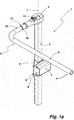
- a stand-up aid 1 comprises a pillar 2 and a erecting rod 3 pivotally connected to the pillar 2.
- the erecting rod 3 is connected to the pillar 2 with the interposition of an articulated member 4.
- the column 2 of the illustrated embodiment is designed in one piece.
- the one square cross-sectional area with rounded corners having column 2 is guided in a guide tube section 5.
- the guide tube section 5 is in the illustrated embodiment, a tube section having the same geometry as the cross-sectional geometry of the column 2, but with an inner diameter, so that this column 2 can dip therein and in the longitudinal direction relative to the guide tube section 5 is displaceable.
- a clamping screw is used, with which the column 2 can be fixed within the guide tube section 5 (not shown). In this way, the height of the erecting bar 3 and thus its pivoting level can be adjusted.
- the guide tube section 5 is connected to a plate 6.
- the plate 6 is part of a connection means for connecting the stand-up aid 1 to the frame of a bed.
- these connection means comprise a U-shaped sleeve 7, which surrounds a carrier, typically the longitudinal beam or longitudinal spar of a bed. With the sleeve 7, the plate 6 cooperates, in such a way that an inserted into the spar holder 8 frame part of the bed can be clamped therein, so that the column 2 is immovably connected to the frame part.
- the Aufrichtestange 3 is executed in the illustrated embodiment angled, and that asymmetrical, so that a shorter leg and a longer leg arise.
- the longer leg of Aufrichtestange 3 serves as a grip portion 9 which a person takes when they sit up with the aid of the stand-up 1 in a bed to which the stand-up 1 is connected, erect and / or would like to get out of this.
- the shorter leg 10 is connected to the connecting or joint member 4.
- the erecting rod 3 is pivotable about the longitudinal axis L of the column 2, as this in FIG. 1 indicated by the arrow.
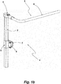
- the hinge member 4, with the Aufrichtestange 3 in the above Art is pivotally connected to the column 2, comprises a locking mechanism.
- This locking mechanism is a pawl mechanism, as it is used in principle when using tool ratchets.
- This locking mechanism is a pivoting movement of the erection bar 3 in the in FIG. 1 shown arrow direction possible, but not in the opposite direction.
- the joint member 4 has a switching mechanism which can be actuated by means of a switch 11. With this switching mechanism, on the one hand, the locking mechanism can be released, so that then the erection bar 3 is pivotable in both directions. Further, by switching the locking mechanism can be set in the opposite direction acting.
- the Aufrichtestange 3 is pivotable about the longitudinal axis of its leg 10 by the hinge member 4 carries a partially dipping in the leg 10 pivot pin and against which the erecting rod 3 is pivotable.
- a slot-like guide 12 is introduced in the leg 10 itself.
- a bolt 13 which sits in the pivot pin of the joint member 4, held engaging.
- the pivoting amount of Aufrichtestange 3 about the longitudinal axis of its leg 10 can be limited.
- position of Aufrichtestange 3 is a further lowering thereby prevented since the bolt 13 on the in FIG. 1 recognizable end of the guide groove 12 is present.
- the Aufschwenkbetrag the Aufrichtestange 3 is limited.
- the stand-up aid 1 can also be connected to another side of the bed with its erection bar. Depending on the orientation of bed use then the erection bar and / or the locking mechanism is adjusted accordingly.
- the stand-up 1 is in the FIGS. 2a, 2b connected to a schematically illustrated frame 14 of a bed 15, otherwise not shown.
- the Aufsteh Vietnamese 1 is attached to a longitudinal spar of the bed frame 14.
- the Aufrichtestange 3 extends with its handle portion 9 on the bordered by the frame 14 vide Chemistry16.
- position of Aufrichtestange 3 is that position from which a person using the Aufsteh Vietnamese 1 takes this person to bring from a prone position to a sitting position.
- the stand-up aid 1 can also be used as a support.
- the person who has already moved from the prone position to the seated end position with the aid of the stand-up aid 1 slips toward the edge of the bed, to which the stand-up aid 1 is connected. This is due to the possible in this direction pivoting the erection bar 3 readily possible.
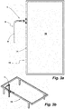
- FIGS. 3a, 3b show a position of Clothingrichtestange 3
- a user sits on the edge of the bed and has already placed his feet on the bottom side.
- FIG. 3 seen, the angled training of Aufrichtestange 3 positively noticeable, since this training leaves a user enough space between In this position, the stand-up aid 1, a person can easily rest on the handle portion 9 and pull up on this from his sitting position in the state or push up.
- the erecting rod 3 with its handle portion 9 even further than in the FIGS. 3a, 3b can be swung out, so that enough space between the handle portion 9 and the edge of the bed 15 is present in order to be able to step away comfortably.
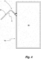
- This position of the erector bar 3 of the stand-up 1 is in FIG. 4 shown in a plan view.
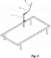
- FIG. 5 yet another position of the stand-up 1 shown.
- the erection bar 3 is pivoted vertically and is in its non-use position.
- the erecting rod 3 can be used to hang certain objects, such as infusion bags can.
- the stand-up 1, when the erection rod 3 is in its use position, for example, in the use position after the FIGS. 2a, 2b also be used to be used as a holder for example, a tray, a Aufstecktisch or the like.
- stand-up aid 1.1 shown corresponds in terms of their design that of the stand-up 1 of the preceding figures.
- the stand-up aid 1.1 differs in terms of their connection means for connecting their column 2.1 to the spar 18 of a bed frame or bed frame, otherwise not shown.
- connecting means a sleeve for connecting the stand-up to a bed frame
- the connection means of the stand-up aid 1.1 is designed as a clamping enclosure 19.
- the Klemmein charged 19 has a U-shaped Holmsuit 20 whose both legs 21, 21.1 are directed away from the pillar 2.1 of the stand-up aid 1.1.
- the spar pad 20 is open at the bottom and is placed on top of the spar 18 from above.
- the pillar 2.1 of the stand-up aid 1.1 is arranged on the back of the U-shaped Holmfact 20.
- the spar holder 20 and the column 2.1 are welded together.
- To fix the Klemmein drawn 19 to the spar 18 is a disposed within the spar holder 20 clamping plate 22 with a planar extension parallel to the legs 21, 21.1.
- Two clamping screws 23, 23.1 pass through the leg 21 of the spar holder 20, wherein this passage serves as a guide for the clamping screws 23, 23.1.
- On the clamping screws 23, 23.1 sits, as shown in the illustration FIG. 7 recognizable, a clamping nut 24, which acts to clamp the clamping plate 22 on the spar 18 against the inside of the leg 21.
- the clamping connection between the spar 18 and the leg 21.1 of the spar holder 20 and the clamping plate 22 is effected by tensioning the clamping nut 24.
- the spar receptacle 20 is particularly suitable for connection to differently designed bed frames or their longitudinal spars, since the stand-up aid 1.1 is placed with their spar receptacle 20 as a connection means from above on a longitudinal spar. Embracing a longitudinal spar, as provided in the object of the stand-up aid 1 with the cuff comprising a spar, is thus not required when using a clamping collar 19. It is also advantageous that the Klemmein charged 19 may have a certain longitudinal extent, whereby a force is introduced over a larger area in the received therein spar. This is advantageous because act on the connected by means of their pillar 2.1 to the spar holder 20 of the clamping enclosure 19 Aufsteh Cei 1.1 when using the same not inconsiderable torsional forces. In this respect, the Klemmein charged 19 without damage and weight-optimized spars to take into account, are used on this also for connecting a stand-up to a bed frame.
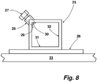
- FIG. 8 schematically shows in a plan view another way of connecting a stand-up by means of its column to a bed frame.
- connecting means for connecting the column a frame part of a bed is a column receptacle 25, which is fastened by means of a fitting plate 26 on the outwardly facing side of a spar of a bed frame. This can be done by means of screws or by a joining process.
- the column receptacle 25 is in FIG. 8 shown in a plan view.
- In the column holder 25 is a square tube piece with an inner width, in which the column of a stand-up can be used with the necessary movement play.
- the inner width of the column receptacle 25 is adapted to the edge length of a pillar also having a square cross-sectional area of a stand-up.
- a special feature of the column holder 25 is that for fixing the column within the column holder 25, a clamping screw 27 is used.
- the clamping screw 27 engages with its threaded shank in a threaded sleeve 28 formed with a complementary internal thread.
- the threaded sleeve 28 is disposed on an edge of the column receptacle 25, wherein the axis of the internally threaded bore of the threaded sleeve 28 in alignment with the bisector of the edge adjacent walls of the column support extends.
- the foot 29 of the clamping screw 27, which is equipped with a rectangular notch 30 in the illustrated embodiment, acts on an edge of a column inserted into the column holder 25.
- the column used in the column holder 25 is pressed in this way by the clamping screw 27 against the inside of the walls 31, 32.
- a column of a stand-up aid inserted into the column receptacle 25 is fixed in the two directions of the opening of the column receptacle 25.
- the height of the stand-up aid is also set up as in the stand-up. 1
- the invention has been described with reference to a stand-up, which is connected from the direction of a person using the stand-up person to the right side of the bed. It is understood that such a stand-up help course to any, especially the other side of the bed can be connected. In such a case, the person using the righting aid is designed or assembled in mirror symmetry with the same lying direction.
Landscapes
- Health & Medical Sciences (AREA)
- Nursing (AREA)
- Life Sciences & Earth Sciences (AREA)
- Animal Behavior & Ethology (AREA)
- General Health & Medical Sciences (AREA)
- Public Health (AREA)
- Veterinary Medicine (AREA)
- Invalid Beds And Related Equipment (AREA)
Abstract
Ein Aufstehhilfe 1 für eine in einem Bett befindliche Person umfasst eine Säule 2 mit Anschlussmitteln zum Anschließen derselben an ein Rahmenteil 14 eines Bettes 15. Zudem umfasst die Aufstehhilfe eine sich in ihrer Benutzungsstellung quer zur Längserstreckung der Säule 2 erstreckende, an das obere Ende der Säule 2 angeschlossen und gegenüber dieser verschwenkbare Aufrichtestange 3. In die gelenkige Verbindung zwischen der Aufrichtestange 3 und der Säule 2 ist ein die eine Schwenkrichtung der Aufrichtestange blockierende und die entgegengesetzte Schwenkrichtung gestattender Sperrmechanismus eingeschaltet oder die gelenkige Verbindung ist durch einen solchen Sperrmechanismus gebildet.A stand-up aid 1 for a person in a bed comprises a column 2 with connecting means for connecting the same to a frame part 14 of a bed 15. In addition, the stand-up comprises a in its position of use transversely to the longitudinal extent of the column 2 extending to the upper end of the column In the articulated connection between the erecting bar 3 and the pillar 2, a locking mechanism blocking a pivoting direction of the erecting bar and permitting the opposite pivoting direction is turned on or the articulated connection is constituted by such a locking mechanism.
Description
Die Erfindung betrifft eine Aufstehhilfe für eine in einem Bett befindliche Person sowie ein damit ausgerüstetes Bett.The invention relates to a stand-up aid for a person in a bed and a bed equipped with it.
Für Verletzte oder auch ältere Personen ist es mitunter nicht immer möglich, sich ohne Hilfsmittel aus der liegenden Position in einem Bett in eine sitzende Position aufzurichten und sich anschließend zum Verlassen des Bettes von diesem zu erheben. Um bezüglich des Aufrichtens einer solchen Person ein Hilfsmittel bereitzustellen, verfügen Pflegebetten oftmals über einen daran angebrachten Bettgalgen. Dieser erstreckt sich ausgehend von dem Kopfende des Bettes über die Liegefläche. Angehängt an diesem Bettgalgen ist ein etwa dreieckförmiger Handgriff. Dieser kann zum Unterstützen des Aufrichtvorganges von einer in dem Bett befindlichen liegenden Person ergriffen werden, um sich daran hoch zu ziehen. Eine Unterstützung zum Aufstehen, d. h. zum Unterstützen des Umsetz- und Aufstehprozesses, damit eine Person aus dem Bett aussteigen kann, ist mit einem solchen Hilfsmittel nicht zu erreichen.For injured or elderly people, it is sometimes not always possible to sit up without assistance from the lying position in a bed in a sitting position and then rise to leave the bed of the latter. In order to provide a tool for erecting such a person, nursing beds often have a bed gallows attached thereto. This extends from the head of the bed on the mattress. Attached to this bed gallows is an approximately triangular handle. This may be grasped by a person in the bed to help pull it up to assist in the erection process. A support to get up, d. H. assisting the transfer and getting-up process so that a person can get out of bed is not achievable with such an aid.
Neben derartigen Bettgalgen sind auch Mobilitätshilfen bekannt geworden, die das Aufstehen von einem Bett erleichtern sollen. Eine derartige Aufstehhilfe ist beispielsweise aus
Eine andere Mobilitätshilfe ist aus
Unerwünscht, jedoch nicht zu vermeiden ist, dass zum selbsttätigen Aufrichten und Aufstehen somit zwei unterschiedliche Mobilitätshilfen benötigt werden - zum Einen ein Bettgalgen für das Aufrichten und zum Anderen eine der vorbeschriebenen Mobilitätshilfen zum Aufstehen. Bettgalgen als Aufrichthilfen werden zwar vielfach eingesetzt, werden jedoch im höchsten Maße als unästhetisch empfunden.Undesirable, but it is unavoidable that two different mobility aids are needed for the self-righting and getting up - on the one hand a bedstead for standing up and on the other hand one of the above-mentioned mobility aids to get up. Although bedsteads are often used as raising aids, they are highly regarded as unaesthetic.
Ausgehend von diesem diskutierten Stand der Technik liegt der Erfindung daher die Aufgabe zugrunde, eine Aufstehhilfe vorzuschlagen, mit der nicht nur der Aufrichtprozess zum Aufrichten aus der liegenden Stellung in eine sitzende Stellung unterstützt werden kann, sondern die ebenfalls als Aufstehhilfe zum Unterstützen eines Aufstehvorganges genutzt werden kann.Based on this discussed prior art, the object of the invention is therefore to propose a stand-up aid, with which not only the erection process for raising from the lying position into a sitting position can be supported, but which are also used as a stand-up aid for supporting a standing-up operation can.
Gelöst wird diese Aufgabe erfindungsgemäß durch eine Aufstehhilfe für eine in einem Bett befindliche Person, umfassend eine Säule mit Anschlussmitteln für das Anschließen derselben an ein Rahmenteil eines Bettes und eine sich in ihrer Benutzungsstellung quer zur Längserstreckung der Säule erstreckende, an das obere Ende der Säule angeschlossene und gegenüber dieser schwenkbare Aufrichtestange, wobei in die gelenkige Verbindung zwischen der Aufrichtestange und der Säule ein die eine Schwenkrichtung der Aufrichtestange blockierender und die entgegengesetzte Schwenkrichtung gestattender Sperrmechanismus eingeschaltet oder die gelenkige Verbindung durch einen solchen Sperrmechanismus gebildet ist.This object is achieved according to the invention by a stand-up aid for a person in a bed, comprising a column with connection means for connecting the same to a frame part of a bed and one in its position of use extending transversely to the longitudinal extension of the column, connected to the upper end of the column and opposite to this pivotable erecting bar, wherein in the hinged connection between the erecting bar and the column, a blocking mechanism permitting one pivoting direction of the erecting bar and allowing the opposite pivoting direction is activated or the articulated connection is formed by such a locking mechanism.
Diese Aufstehhilfe ist an ein Rahmenteil des Bettes angeschlossen. Typischerweise wird es sich bei dem Bett, an das eine solche Aufstehhilfe anzuschließen ist, um ein Kranken- oder Pflegebett handeln. Derartige Betten verfügen über Rahmenteile sowie Querstreben aus Metallprofilen, mithin Rahmenteile, die besonders geeignet sind, um die auf eine solche Aufstehhilfe bei ihrer Benutzung einwirkenden Kräfte aufzunehmen. Die Aufstehhilfe selbst umfasst eine mit Anschlussmitteln an ein solches Rahmenteil ausgerüstete Säule, eine Aufrichtestange und ein Verbindungs- bzw. Gelenkglied zum gelenkigen Anschließen der Aufrichtestange an die Säule, über welches Verbindungsglied eine Verschwenkbarkeit der Aufrichtestange in horizontaler Richtung ermöglicht ist. Die Aufrichtestange selbst befindet sich in einer Ebene quer zur Längserstreckung der Säule und ist daher ausgelegt, über die Liegefläche greifen zu können. Die Aufrichtestange ist gegenüber der Säule verschwenkbar und kann somit aus einer Stellung, in der diese über die Liegefläche greift in eine Stellung gebracht werden, in der diese parallel zur Längsseite des Bettes ausgerichtet ist oder auch darüber hinaus weiter aufgeschwenkt werden kann. Die gelenkige Verbindung zwischen der Aufrichtestange und der Säule ist derart konzipiert, dass eine Schwenkbewegung der Aufrichtestange in die eine Richtung bei einer Benutzung der Aufstehhilfe zum Unterstützen des Aufricht- und/oder Aufstehvorganges möglich ist, während eine Schwenkbewegung in die entgegengesetzte Richtung gesperrt bzw. blockiert ist. Blockiert ist bei einer Benutzung der Aufstehhilfe die Schwenkrichtung der Aufrichtestange, die in Richtung zu der die Aufstehhilfe benutzenden Person gerichtet ist. Aus diesem Grunde kann sich eine die Aufstehhilfe benutzende Person an der Aufrichtestange hochziehen, mithin eine Zugbelastung ausüben. Die Verschwenkbarkeit der Aufrichtestange in die andere, nicht gesperrte Schwenkrichtung erlaubt es, dass die Aufrichtestange, nachdem sich die Person in eine sitzende Stellung gebracht hat, von der Person weggeschwenkt werden kann, um sodann wiederum als Hilfe genutzt werden zu können, damit die zunächst auf der Liegefläche befindliche Sitzposition in eine solche Sitzposition geändert werden kann, aus der sich die Person erheben, mithin aus dem Bett aufstehen kann. Befindet sich die Person in einer sitzenden Stellung, in der die Füße bodenseitig neben dem Bett aufgestellt sind, kann sich die Person an der Aufrichtestange abstützen, um sich in eine Stehposition zu bringen. Ohne Weiteres ist es möglich, dass die Aufrichtestange weiter ausgeschwenkt wird und sich die aufstehende Person auch insofern an dieser hochziehen kann, da eine Schwenkbewegung in die entgegensetzte Richtung blockiert ist. Steht die aufgestandene Person, kann sie sich an der Aufrichtstange stehend festhalten.This stand-up aid is connected to a frame part of the bed. Typically, the bed to which such a stand-up aid is to be connected will be a hospital or nursing bed. Such beds have frame parts and cross struts of metal profiles, thus frame parts, which are particularly suitable to accommodate the forces acting on such a stand-up in their use forces. The stand-up aid itself comprises a pillar equipped with connection means to such a frame part, an erecting rod and a connecting or articulating member for pivotally connecting the erecting rod to the column, via which connecting member a pivotability of the erection rod in the horizontal direction is made possible. The erection bar itself is located in a plane transverse to the longitudinal extent of the column and is therefore designed to be able to reach over the lying surface. The erecting rod is pivotable relative to the column and can thus be brought from a position in which this engages over the lying surface in a position in which it is aligned parallel to the longitudinal side of the bed or beyond can be further pivoted. The articulated connection between the erection bar and the pillar is designed to permit pivotal movement of the erection bar in one direction when using the stand-up aid to assist in the erection and / or raising operation while blocking or blocking pivotal movement in the opposite direction is. When using the stand-up aid, the direction of pivoting of the erection bar, which is directed in the direction of the person using the standing-up aid, is blocked. For this reason, a person using the Aufstehhilfe can pull up on the erection bar, thus exert a tensile load. The pivoting of the erection bar in the other, not locked pivoting direction allows the erection bar, after the person has moved into a sitting position, can be pivoted away from the person, and then again can be used as an aid, so that at first the lying surface seat position can be changed into such a sitting position from which the person rise, therefore, can get up from the bed. Is the person in a sitting position, in which the feet on the bottom side Next to the bed, the person can lean on the erection bar to get into a standing position. Without further ado, it is possible that the erecting rod is further swung out and the upright person can also pull up to this extent, since a pivoting movement is blocked in the opposite direction. If the person stands up, they can hold on to the erecting bar.
In vielen Fällen wird man für den umgekehrten Vorgang des sich Auf-das-Bett-Setzens und sich erneut in die Liegend-Position bringen die Aufstehhilfe nicht benötigen. Sollte dieses dennoch gewünscht sein, wird man eine solche Aufstehhilfe, wie dieses in einem bevorzugten Ausführungsbeispiel der Fall ist, mit einem lösbaren Sperrmechanismus ausstatten, was ohnehin bevorzugt ist. Auch bei diesen Vorgängen wird die Aufrichtestange in derselben Richtung belastet wie bei der Unterstützung des Aufrichtens und Aufsetzens. Insofern wird man bei einer Benutzung dieser Aufstehhilfe zum Hinsetzen und zum Liegen schrittweise den Sperrmechanismus lösen, damit in diese Richtung die Aufrichtestange nachgeführt werden kann, bevor man typischerweise sich vom Hinsetzen in die Liegen-Position begibt.In many cases you will not need the stand-up aid for the reverse process of setting yourself up on the bed and getting yourself back into the lying position. Should this still be desired, one will provide such a stand-up aid, as is the case in a preferred embodiment, with a releasable locking mechanism, which is anyway preferred. Also in these operations, the erection bar is loaded in the same direction as in the support of erection and placement. In this respect, when using this stand-up aid for sitting down and lying down, you will gradually release the locking mechanism so that the erection bar can be tracked in this direction before you typically move from sitting down to the lying position.
Vorzugsweise ist eine solche Aufrichthilfe mit einer Umschalteinrichtung zum Umschalten der Sperrrichtung ausgestattet. Dieses kann genutzt werden, um aufgrund einer unterschiedlich gewünschten Sperrrichtung in Abhängigkeit von einer Anbringung der Aufstehhilfe am Bett und derjenigen Richtung in der eine Person die Haltekraft der Aufstehhilfe in Anspruch nimmt, einzustellen.Preferably, such a Aufrichthilfe is equipped with a switching device for switching the reverse direction. This can be used to adjust due to a different desired locking direction in response to an attachment of the stand-up on the bed and the direction in which a person takes the holding force of the stand-up to complete.
Ein solcher Sperrmechanismus kann nach Art einer Sperrklinkenmechanik ausgeführt sein, wie diese bei Knarren als Werkzeuge zum Einsatz gelangen. Zur Realisierung des vorbeschriebenen Sperrmechanismus können auch andere Mechaniken als Sperrklinkemechaniken zum Einsatz kommen.Such a locking mechanism may be carried out in the manner of a pawl mechanism, as they are used as tools in ratchets. To implement the above-described locking mechanism and other mechanisms can be used as Sperrklinkemechaniken.
Die Säule der Aufstehhilfe ist zweckmäßigerweise zwei- oder auch mehrteilig ausgeführt. Das unterste Säulenteil ist an das Gestell des Bettes angeschlossen. Dieses Säulenteil kann als Hohlprofil ausgeführt sein, sodass ein zweites Säulenteil in dieses eintauchen kann und darin längsverschiebbar und gegenüber dem ersten Säulenteil arretierbar ist. In einem solchen Fall trägt das zweite Säulenteil, sollte die Säule aus zwei Säulenteil bestehen, die Aufrichtestange. Sollte die Säule aus mehr als zwei Teilen bestehen, wird die Aufrichtestange von dem obersten Säulenteil getragen.The column of the stand-up is expediently made two or more parts. The lowest column part is connected to the frame of the bed. This pillar part can be designed as a hollow profile, so that a second column part can dive into this and is longitudinally displaceable and lockable relative to the first column part. In such a case, if the pillar consists of two pillar members, the second pillar member carries the erecting rod. Should the column consist of more than two parts, the erection bar is carried by the uppermost column part.
Vorzugsweise ist die Aufrichtestange gewinkelt ausgeführt, und zwar unsymmetrisch, sodass diese einen kürzeren und einen längeren Schenkel aufweist. Mit dem kürzeren Schenkel ist die Aufrichtestange an die Säule gelenkig in der vorbeschriebenen Art und Weise angeschlossen. Der längere Schenkel der Aufrichtestange bildet sodann den eigentlichen Griffabschnitt, den ein Benutzer für die Benutzung der Aufstehhilfe ergreift. Die abgewinkelte Ausführung der Aufrichtestange hat zum Vorteil, dass bei einer Anbringung der Säule unmittelbar am Rahmen des Bettes und somit unmittelbar benachbart zur Liegefläche sich der Griffabschnitt mit Abstand zum Rand der Liegefläche befindet, wenn eine die Aufrichthilfe benutzende Person sitzt und ihre Füße bodenseitig aufgestellt hat.Preferably, the erection bar is designed angled, namely asymmetrical, so that it has a shorter and a longer leg. With the shorter leg, the erecting bar is pivotally connected to the column in the manner described above. The longer leg of Aufrichtestange then forms the actual handle portion, which engages a user for the use of the stand-up. The angled design of the erection bar has the advantage that when attaching the column directly to the frame of the bed and thus immediately adjacent to the lying surface, the handle portion is at a distance from the edge of the bed, when a person using the Aufrichthilfe person sits and their feet has placed on the bottom side ,
Die Aufrichtestange kann insgesamt oder auch nur in Bezug auf ihren Griffabschnitt auch als Bügel ausgeführt sein.The Aufrichtestange can be performed as a whole or even with respect to their handle portion as a bracket.
In einer Weiterbildung ist vorgesehen, dass die Aufrichtestange sich aus einer horizontalen oder wesentlich horizontalen Benutzungsstellung in eine vertikale oder vertikal ähnliche Nichtbenutzungsstellung aufschwenken lässt. In einem solchen Fall kann die Aufrichtestange auch für andere Zwecke genutzt werden, beispielsweise zum Anhängen eine Infusionsbeutels. Bei einer gewinkelt ausgeführten Aufrichtestange ist es zweckmäßig, diese Aufschwenkbewegung dadurch zu ermöglichen, dass der kürzere Schenkel der Aufrichtestange um seine Längsachse verschwenkt wird. Erreichen lässt sich dieses dadurch, dass das Verbindungsglied, über das die Aufrichtestange mit der Säule verbunden ist, einen Schwenkzapfen aufweist, auf dem der kürzere Schenkel der Aufrichtestange schwenkbar sitzt. Gehalten werden kann die Aufrichtestange an einem Schwenkzapfen durch einen in eine langlochartige Führungsnut des Schenkels eingreifenden und in dem Schwenkzapfen des Verbindungsgliedes festgesetzten Bolzen.In a further development it is provided that the erection bar can be swung out of a horizontal or substantially horizontal use position into a vertical or vertically similar non-use position. In such a case, the erecting bar can also be used for other purposes, such as attaching an infusion bag. In the case of an angled erecting rod, it is expedient to allow this pivoting movement in that the shorter leg of the erection rod is pivoted about its longitudinal axis. This can be achieved in that the connecting member, via which the erection bar is connected to the column, has a pivot pin on which the shorter leg of the erection bar is pivotally seated. The erecting bar can be held on a pivot pin by a bolt engaging in a slot-like guide groove of the leg and fixed in the pivot pin of the connecting link.
Nachfolgend ist die Erfindung anhand eines Ausführungsbeispiels unter Bezugnahme auf die beigefügten Figuren beschrieben. Es zeigen:
- Fig. 1a, 1b:
- Eine perspektivische Ansicht einer Aufstehhilfe aus einer ersten Blickrichtung (
Figur 1a ) und aus einer zweiten Blickrichtung (Figur 1 b) , - Fig. 2a, 2b:
- eine Draufsicht auf die
Aufstehhilfe der Figur 1 , angeschlossen an den Rahmen eines Bettes (Figur 2a ) sowie in einer perspektivischen Darstellung (Figur 2b ), jeweils in einer ersten Stellung der Aufstehhilfe, - Fig. 3a, 3b:
- eine Draufsicht auf die
Aufstehhilfe der Figur 1 , angeschlossen an den Rahmen eines Bettes (Figur 3a ) sowie in einer perspektivischen Darstellung (Figur 3b ), jeweils in einer weiteren Stellung der Aufstehhilfe, - Fig. 4:
- eine Draufsicht auf die
Aufstehhilfe der Figur 1 , angeschlossen an den Rahmen eines Bettes in einer noch weiteren Stellung der Aufstehhilfe, - Fig. 5:
- eine perspektivische Darstellung der an das Bett angeschlossenen Aufstehhilfe in einer Nichtbenutzungsstellung,
- Fig. 6:
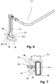
- eine perspektivische Ansicht einer Aufstehhilfe, die prinzipiell aufgebaut ist wie diejenige der vorangegangenen Figuren, welche Aufstehhilfe unter Verwendung eines anderen Anschlussmittels an dem Rahmenteil eines Bettgestells angeschlossen ist,
- Fig. 7:
- eine Stirnseitenansicht des Anschlussmittels der
Figur 6 und - Fig. 8:
- eine Draufsicht auf noch ein weiteres Anschlussmittel zum Anschließen einer Aufstehhilfe an ein Bettgestell in einer Draufsicht.
- Fig. 1a, 1b:
- A perspective view of a stand-up aid from a first viewing direction (
FIG. 1a ) and from a second line of sight (FIG. 1 b) . - 2a, 2b:
- a plan view of the stand up the
FIG. 1 connected to the frame of a bed (FIG. 2a ) as well as in a perspective representation (FIG. 2b ), in each case in a first position of the stand-up aid, - 3a, 3b:
- a plan view of the stand up the
FIG. 1 connected to the frame of a bed (FIG. 3a ) as well as in a perspective representation (FIG. 3b ), each in a further position of the stand-up, - 4:
- a plan view of the stand up the
FIG. 1 connected to the frame of a bed in yet another position of the stand-up aid, - Fig. 5:
- a perspective view of the stand-up aid connected to the bed in a non-use position,
- Fig. 6:
- a perspective view of a stand-up, which is basically constructed as that of the preceding figures, which stand-up is connected using another connection means to the frame part of a bed frame,
- Fig. 7:
- an end view of the connection means of
FIG. 6 and - Fig. 8:
- a plan view of yet another connection means for connecting a stand-up to a bed frame in a plan view.
Eine Aufstehhilfe 1 umfasst eine Säule 2 sowie eine schwenkbar an die Säule 2 angeschlossene Aufrichtestange 3. Die Aufrichtestange 3 ist unter Zwischenschaltung eines Gelenkgliedes 4 an die Säule 2 angeschlossen.A stand-up
Die Säule 2 des dargestellten Ausführungsbeispiels ist einteilig ausgeführt. Die eine quadratische Querschnittsfläche mit gerundeten Ecken aufweisende Säule 2 ist in einem Führungsrohrabschnitt 5 geführt. Der Führungsrohrabschnitt 5 ist bei dem dargestellten Ausführungsbeispiel ein Rohrabschnitt mit derselben Geometrie wie die Querschnittsgeometrie der Säule 2, jedoch mit einem Innendurchmesser, sodass diese Säule 2 darin eintauchen kann und in Längsrichtung gegenüber dem Führungsrohrabschnitt 5 verschiebbar ist. In eine Wand des Führungsrohrabschnittes 5 ist eine Klemmschraube eingesetzt, mit der die Säule 2 innerhalb des Führungsrohrabschnittes 5 festgesetzt werden kann (nicht dargestellt). Auf diese Weise lässt sich die Höhe der Aufrichtestange 3 und damit ihre Schwenkebene einstellen. Der Führungsrohrabschnitt 5 ist an eine Platte 6 angeschlossen. Die Platte 6 ist Teil eines Anschlussmittels zum Anschließen der Aufstehhilfe 1 an das Gestell eines Bettes. Neben der Platte 6 umfassen diese Anschlussmittel eine U-förmig ausgeführte Manschette 7, die einen Träger, typischerweise den Längsträger bzw. Längsholm eines Bettes umgreift. Mit der Manschette 7 wirkt die Platte 6 zusammen, und zwar dergestalt, dass ein in die Holmaufnahme 8 eingesetztes Rahmenteil des Bettes darin verspannt werden kann, sodass die Säule 2 unverrückbar an das Rahmenteil angeschlossen ist.The
Die Aufrichtestange 3 ist bei dem dargestellten Ausführungsbeispiel gewinkelt ausgeführt, und zwar unsymmetrisch, sodass sich ein kürzerer Schenkel und ein längerer Schenkel ergeben. Der längere Schenkel der Aufrichtestange 3 dient als Griffabschnitt 9, den eine Person ergreift, wenn sie sich unter Zuhilfenahme der Aufstehhilfe 1 in einem Bett, an das die Aufstehhilfe 1 angeschlossen ist, aufrichten und/oder aus diesem aufstehen möchte. Der kürzere Schenkel 10 ist an das Verbindungs- bzw. Gelenkglied 4 angeschlossen. Die Aufrichtestange 3 ist um die Längsachse L der Säule 2 schwenkbar, wie dieses in
Das Gelenkglied 4, mit dem die Aufrichtestange 3 in der vorbeschriebenen Art verschwenkbar an die Säule 2 angeschlossen ist, umfasst einen Sperrmechanismus. Bei diesem Sperrmechanismus handelt es sich um eine Klinkenmechanik, wie diese grundsätzlich bei der Verwendung von Werkzeugknarren zum Einsatz gelangt. Durch diesen Sperrmechanismus ist eine Schwenkbewegung der Aufrichtestange 3 in der in
Neben der vorbeschriebenen Verschwenkbarkeit der Aufrichtestange 3 in einer horizontalen Ebene, welches die Benutzungsstellung der Aufrichtestange 3 darstellt, ist diese auch um die Längsachse ihres Schenkels 10 aufschwenkbar. In eine nach oben aufgeschwenkte Stellung wird man die Aufrichtestange 3 bringen, wenn diese nicht benötigt wird. Die aufgerichtete Stellung der Aufrichtestange 3 für die Zwecke eines Aufrichtens und/oder Aufstehens wird im Rahmen dieser Ausführung auch als Nichtbenutzungsstellung angesprochen. Dieses bedeutet nicht, dass in dieser Stellung die aufgerichtete Aufrichtestange nicht für andere Zwecke genutzt werden kann.In addition to the above-described pivoting the
Verschwenkbar ist die Aufrichtestange 3 um die Längsachse ihres Schenkels 10, indem das Gelenkglied 4 einen in den Schenkel 10 teilweise eintauchenden Schwenkzapfen trägt und gegenüber dem die Aufrichtestange 3 schwenkbar ist. In den Schenkel 10 selbst ist eine langlochartige Führungsnut 12 eingebracht. In dieser ist ein Bolzen 13, der in dem Schwenkzapfen des Gelenkgliedes 4 sitzt, eingreifend gehalten. Dadurch ist der Verschwenkbetrag der Aufrichtestange 3 um die Längsachse seines Schenkels 10 begrenzbar. In der in
Die Aufstehhilfe 1 kann mit ihrer Aufrichtestange auch an eine andere Bettseite angeschlossen werden. Je nach der Ausrichtung der Bettbenutzung ist dann die Aufrichtestange und/oder der Sperrmechanismus entsprechend anzupassen.The stand-up
Die Aufstehhilfe 1 ist in den
Aus der perspektivischen Darstellung der
Muss eine Person aus dem Bett 15 aufstehen, kann hierfür ebenfalls die Aufstehhilfe 1 unterstützend benutzt werden. Zu diesem Zweck rutscht die Person, die sich bereits unter Zuhilfenahme der Aufstehhilfe 1 aus der Liegend-Position in die Sitzendposition gebracht hat, in Richtung zu dem Bettrand hin, an den die Aufstehhilfe 1 angeschlossen ist. Dieses ist aufgrund der in dieser Richtung möglichen Verschwenkbarkeit der Aufrichtestange 3 ohne Weiteres möglich.If a person has to get up from
Um ein Verlassen des Bettes 15 zu vereinfachen, ist bei dem dargestellten Ausführungsbeispiel vorgesehen, dass die Aufrichtestange 3 mit ihrem Griffabschnitt 9 noch weiter, als in den
Während die Aufstehhilfe 1 in den
Die Aufstehhilfe 1 kann, wenn sich die Aufrichtestange 3 in ihrer Benutzungsstellung befindet, beispielsweise in der Benutzungsstellung nach den
Die in
Die Holmaufnahme 20 eignet sich in besonderer Weise zum Anschließen an unterschiedlich ausgelegte Bettgestelle bzw. deren Längsholme, da die Aufstehhilfe 1.1 mit ihrer Holmaufnahme 20 als Anschlussmittel von oben auf einen Längsholm aufgesetzt wird. Ein Umfassen eines Längsholms, wie dieses beim Gegenstand der Aufstehhilfe 1 mit der einen Holm umfassenden Manschette vorgesehen ist, ist somit bei Verwendung einer Klemmeinfassung 19 nicht erforderlich. Vorteilhaft ist zudem, dass die Klemmeinfassung 19 eine gewisse Längserstreckung aufweisen kann, wodurch eine Krafteinleitung über eine größere Fläche in den darin aufgenommenen Holm eingeleitet wird. Dieses ist vorteilhaft, da über die mittels ihrer Säule 2.1 an die Holmaufnahme 20 der Klemmeinfassung 19 angebundene Aufstehhilfe 1.1 bei einer Benutzung derselben nicht unbeträchtliche Torsionskräfte wirken. Insofern kann die Klemmeinfassung 19 ohne eine Beschädigung auch gewichtsoptimierter Holme in Kauf zu nehmen, auf diese auch zum Anschließen einer Aufstehhilfe an ein Bettgestell eingesetzt werden.The
Bei Verwendung eines solchen Anschlussmittels ist die Höhe der Aufstehhilfe ebenso einrichtbar wie bei der Aufstehhilfe 1.When using such a connection means, the height of the stand-up aid is also set up as in the stand-up. 1
Auftretende Querkräfte bei einer Benutzung der Aufstehhilfe werden über die Länge der Beschlagplatte 26 großflächig in den angrenzenden Holm 33 eingeleitet.Occurring shear forces when using the stand-up aid are introduced over the length of the
Die Erfindung ist anhand einer Aufstehhilfe beschrieben worden, die aus Blickrichtung einer die Aufstehhilfe nutzenden Person an die rechte Bettseite angeschlossen wird. Es versteht sich, dass eine solche Aufstehhilfe selbstverständlich an beliebige, insbesondere auch die andere Bettseite angeschlossen werden kann. In einem solchen Fall ist bei gleicher Liegerichtung der die Aufrichtehilfe nutzende Person diese spiegelsymmetrisch konzipiert bzw. zusammengesetzt.The invention has been described with reference to a stand-up, which is connected from the direction of a person using the stand-up person to the right side of the bed. It is understood that such a stand-up help course to any, especially the other side of the bed can be connected. In such a case, the person using the righting aid is designed or assembled in mirror symmetry with the same lying direction.
Die Erfindung ist anhand von Ausführungsbeispielen beschrieben worden. Ohne den Umfang der geltenden Ansprüche zu verlassen, ergeben sich für einen Fachmann zahlreiche weitere Ausgestaltungsmöglichkeiten, die beanspruchte Erfindung umzusetzen.
Claims (15)
Priority Applications (1)
| Application Number | Priority Date | Filing Date | Title |
|---|---|---|---|
| PL16166125T PL3085348T3 (en) | 2015-04-24 | 2016-04-20 | Means for aiding standing up and bed incorporating same |
Applications Claiming Priority (1)
| Application Number | Priority Date | Filing Date | Title |
|---|---|---|---|
| DE202015102058.9U DE202015102058U1 (en) | 2015-04-24 | 2015-04-24 | Stand-up aid and bed equipped with it |
Publications (2)
| Publication Number | Publication Date |
|---|---|
| EP3085348A1 true EP3085348A1 (en) | 2016-10-26 |
| EP3085348B1 EP3085348B1 (en) | 2021-07-14 |
Family
ID=53443567
Family Applications (1)
| Application Number | Title | Priority Date | Filing Date |
|---|---|---|---|
| EP16166125.1A Active EP3085348B1 (en) | 2015-04-24 | 2016-04-20 | Means for aiding standing up and bed incorporating same |
Country Status (5)
| Country | Link |
|---|---|
| US (1) | US10272005B2 (en) |
| EP (1) | EP3085348B1 (en) |
| DE (1) | DE202015102058U1 (en) |
| ES (1) | ES2893756T3 (en) |
| PL (1) | PL3085348T3 (en) |
Cited By (1)
| Publication number | Priority date | Publication date | Assignee | Title |
|---|---|---|---|---|
| GB2572652A (en) * | 2018-04-07 | 2019-10-09 | Rowland Wood Oliver | Improvements in bedside assist handrails and their attachment |
Families Citing this family (11)
| Publication number | Priority date | Publication date | Assignee | Title |
|---|---|---|---|---|
| US11129906B1 (en) | 2016-12-07 | 2021-09-28 | David Gordon Bermudes | Chimeric protein toxins for expression by therapeutic bacteria |
| US10285887B2 (en) * | 2017-05-07 | 2019-05-14 | FootAnchor LLC | Apparatus for rising to a sitting position utilizing a leg anchor |
| US11052005B2 (en) | 2017-09-19 | 2021-07-06 | Stryker Corporation | Patient support apparatus with handles for patient ambulation |
| US11116680B2 (en) | 2017-09-19 | 2021-09-14 | Stryker Corporation | Patient support apparatus for controlling patient ingress and egress |
| US11160705B2 (en) | 2017-10-20 | 2021-11-02 | Stryker Corporation | Adjustable patient support apparatus for assisted egress and ingress |
| CN109009203A (en) * | 2018-08-29 | 2018-12-18 | 江苏兴鑫医用设备有限公司 | Photography level bed |
| KR102374728B1 (en) * | 2019-03-06 | 2022-03-16 | 전북대학교산학협력단 | Detachable fall-resistant bed auxiliary handle |
| CN110507348B (en) * | 2019-08-30 | 2022-11-29 | 东软医疗系统股份有限公司 | Bed board locking device and scanning bed |
| US11229735B1 (en) | 2020-03-03 | 2022-01-25 | Miguel Alves | IV pole clamp |
| CN113907990B (en) * | 2021-10-12 | 2024-03-19 | 广东省中医院(广州中医药大学第二附属医院、广州中医药大学第二临床医学院、广东省中医药科学院) | Lying position resetting auxiliary device for orthopedics |
| US11877968B1 (en) * | 2022-04-26 | 2024-01-23 | Marilyn Roberts | Extendable safety handle for benches |
Citations (8)
| Publication number | Priority date | Publication date | Assignee | Title |
|---|---|---|---|---|
| US4932090A (en) * | 1989-04-12 | 1990-06-12 | Johansson Paul J | Movable support bar |
| DE29709508U1 (en) | 1997-05-31 | 1997-08-28 | Vauth-Sagel GmbH & Co, 33034 Brakel | Mobility aid for / on a care bed |
| DE19716249A1 (en) | 1996-04-23 | 1997-11-06 | Maurer Maschb Gmbh | Sitting-up aid for bedridden patients |
| US6039293A (en) * | 1996-04-23 | 2000-03-21 | Dipl.-Ing. Klaus Haken | Auxiliary device for bed-ridden and disabled patients |
| DE20307477U1 (en) | 2003-05-14 | 2003-07-10 | Wölfel, Rainer, 95183 Trogen | Transport device for moving nursing bed, has sleigh with rounded handle movable along underframe |
| US20040181877A1 (en) * | 1998-09-09 | 2004-09-23 | Troy Miller | Assist device for getting into and out of sitting or prone positions on beds and similar furniture |
| GB2420270A (en) * | 2004-10-22 | 2006-05-24 | Simon Griffin | A device to aid the user to sit up whilst in bed |
| US20070044242A1 (en) * | 2005-09-01 | 2007-03-01 | Banks Patricia M | Providing mobility support |
Family Cites Families (7)
| Publication number | Priority date | Publication date | Assignee | Title |
|---|---|---|---|---|
| US2981959A (en) * | 1957-06-27 | 1961-05-02 | Inez U Burnham | Supporting device for invalids |
| US4193147A (en) * | 1978-07-10 | 1980-03-18 | Fischer Edwin L | Cantilevered lifting and transporting device |
| US6311942B1 (en) * | 1999-03-04 | 2001-11-06 | Lenjoy Engineering, Inc. | Bedside cane holder |
| US6961972B2 (en) * | 2001-10-17 | 2005-11-08 | Gordon Zachary Pendell | Apparatus to aid in entering and exiting a bed |
| US20060130238A1 (en) * | 2004-07-16 | 2006-06-22 | Robyn Smith | Bed side rail method and apparatus |
| US7805789B1 (en) * | 2009-02-27 | 2010-10-05 | Mark Ronald Dean | Assist handle for a bed |
| US9120208B2 (en) * | 2009-10-05 | 2015-09-01 | WAGIC, Inc | Handled ratcheting tool with a flip out handle |
-
2015
- 2015-04-24 DE DE202015102058.9U patent/DE202015102058U1/en active Active
-
2016
- 2016-04-20 EP EP16166125.1A patent/EP3085348B1/en active Active
- 2016-04-20 PL PL16166125T patent/PL3085348T3/en unknown
- 2016-04-20 ES ES16166125T patent/ES2893756T3/en active Active
- 2016-04-22 US US15/136,666 patent/US10272005B2/en active Active
Patent Citations (8)
| Publication number | Priority date | Publication date | Assignee | Title |
|---|---|---|---|---|
| US4932090A (en) * | 1989-04-12 | 1990-06-12 | Johansson Paul J | Movable support bar |
| DE19716249A1 (en) | 1996-04-23 | 1997-11-06 | Maurer Maschb Gmbh | Sitting-up aid for bedridden patients |
| US6039293A (en) * | 1996-04-23 | 2000-03-21 | Dipl.-Ing. Klaus Haken | Auxiliary device for bed-ridden and disabled patients |
| DE29709508U1 (en) | 1997-05-31 | 1997-08-28 | Vauth-Sagel GmbH & Co, 33034 Brakel | Mobility aid for / on a care bed |
| US20040181877A1 (en) * | 1998-09-09 | 2004-09-23 | Troy Miller | Assist device for getting into and out of sitting or prone positions on beds and similar furniture |
| DE20307477U1 (en) | 2003-05-14 | 2003-07-10 | Wölfel, Rainer, 95183 Trogen | Transport device for moving nursing bed, has sleigh with rounded handle movable along underframe |
| GB2420270A (en) * | 2004-10-22 | 2006-05-24 | Simon Griffin | A device to aid the user to sit up whilst in bed |
| US20070044242A1 (en) * | 2005-09-01 | 2007-03-01 | Banks Patricia M | Providing mobility support |
Cited By (2)
| Publication number | Priority date | Publication date | Assignee | Title |
|---|---|---|---|---|
| GB2572652A (en) * | 2018-04-07 | 2019-10-09 | Rowland Wood Oliver | Improvements in bedside assist handrails and their attachment |
| GB2572652B (en) * | 2018-04-07 | 2022-08-24 | Rowland Wood Oliver | Improvements in bedside assist handrails and their attachment |
Also Published As
| Publication number | Publication date |
|---|---|
| US10272005B2 (en) | 2019-04-30 |
| US20160310340A1 (en) | 2016-10-27 |
| DE202015102058U1 (en) | 2015-05-28 |
| EP3085348B1 (en) | 2021-07-14 |
| PL3085348T3 (en) | 2021-12-27 |
| ES2893756T3 (en) | 2022-02-10 |
Similar Documents
| Publication | Publication Date | Title |
|---|---|---|
| EP3085348B1 (en) | Means for aiding standing up and bed incorporating same | |
| EP0369256B1 (en) | Hinge ladder | |
| DE102005038030B4 (en) | Stand-up wheelchair | |
| DE202019005729U1 (en) | Folding chair, folding lounger and folding chair frame for it | |
| EP0159562A2 (en) | Lifting chair | |
| CH694982A5 (en) | Stand-up wheelchair. | |
| EP2921151A1 (en) | Mobility aid | |
| DE102014115552B4 (en) | Side rails for a hospital and / or nursing bed | |
| EP3233013B1 (en) | Folding wheelchair | |
| DE202005019582U1 (en) | Head rest for wheel chair, has retaining unit for attachment at seat unit and two arms movably supported at retaining unit, where head rest is designed as folding barricade in operating condition of wheel chair | |
| DE202006006004U1 (en) | Bed frame has back supporting part or component of back supporting part which is connected by coupler with upper side supporting part | |
| EP0853936B1 (en) | Bath lift for elderly and disabled persons | |
| DE102018126293B4 (en) | Slatted frame | |
| DE19828877A1 (en) | Hospital bed support | |
| DE1291479B (en) | Folding armchair, especially for the beach and garden | |
| DE102017122435B3 (en) | hoist | |
| DE10342328B4 (en) | Height-adjustable wallpapering table | |
| DE202016105549U1 (en) | standing up | |
| CH407452A (en) | Hospital table | |
| DE3009073A1 (en) | ADJUSTABLE FURNITURE | |
| DE10014258B4 (en) | Medical bed intended for the sick | |
| DE4110572A1 (en) | Adjustable height work platform supports for construction work - have telescopic extensions from rigid frame base, with slot joint to cross member for easier adjustment | |
| DE2247228C3 (en) | Bed, especially sick bed | |
| DE19802741A1 (en) | Ground support for ladder or frame structure | |
| EP2409675B1 (en) | Actuation device for a turning device for the movement of patients with pulmonary diseases |
Legal Events
| Date | Code | Title | Description |
|---|---|---|---|
| PUAI | Public reference made under article 153(3) epc to a published international application that has entered the european phase |
Free format text: ORIGINAL CODE: 0009012 |
|
| AK | Designated contracting states |
Kind code of ref document: A1 Designated state(s): AL AT BE BG CH CY CZ DE DK EE ES FI FR GB GR HR HU IE IS IT LI LT LU LV MC MK MT NL NO PL PT RO RS SE SI SK SM TR |
|
| AX | Request for extension of the european patent |
Extension state: BA ME |
|
| STAA | Information on the status of an ep patent application or granted ep patent |
Free format text: STATUS: REQUEST FOR EXAMINATION WAS MADE |
|
| 17P | Request for examination filed |
Effective date: 20170425 |
|
| RBV | Designated contracting states (corrected) |
Designated state(s): AL AT BE BG CH CY CZ DE DK EE ES FI FR GB GR HR HU IE IS IT LI LT LU LV MC MK MT NL NO PL PT RO RS SE SI SK SM TR |
|
| STAA | Information on the status of an ep patent application or granted ep patent |
Free format text: STATUS: EXAMINATION IS IN PROGRESS |
|
| 17Q | First examination report despatched |
Effective date: 20191213 |
|
| GRAP | Despatch of communication of intention to grant a patent |
Free format text: ORIGINAL CODE: EPIDOSNIGR1 |
|
| STAA | Information on the status of an ep patent application or granted ep patent |
Free format text: STATUS: GRANT OF PATENT IS INTENDED |
|
| INTG | Intention to grant announced |
Effective date: 20210114 |
|
| GRAS | Grant fee paid |
Free format text: ORIGINAL CODE: EPIDOSNIGR3 |
|
| RAP1 | Party data changed (applicant data changed or rights of an application transferred) |
Owner name: REHASTAGE GMBH |
|
| RIN1 | Information on inventor provided before grant (corrected) |
Inventor name: HEIDINGSFELDER-BONGARD, BRIGITTA |
|
| GRAA | (expected) grant |
Free format text: ORIGINAL CODE: 0009210 |
|
| STAA | Information on the status of an ep patent application or granted ep patent |
Free format text: STATUS: THE PATENT HAS BEEN GRANTED |
|
| AK | Designated contracting states |
Kind code of ref document: B1 Designated state(s): AL AT BE BG CH CY CZ DE DK EE ES FI FR GB GR HR HU IE IS IT LI LT LU LV MC MK MT NL NO PL PT RO RS SE SI SK SM TR |
|
| REG | Reference to a national code |
Ref country code: GB Ref legal event code: FG4D Free format text: NOT ENGLISH |
|
| REG | Reference to a national code |
Ref country code: DE Ref legal event code: R096 Ref document number: 502016013398 Country of ref document: DE |
|
| REG | Reference to a national code |
Ref country code: IE Ref legal event code: FG4D Free format text: LANGUAGE OF EP DOCUMENT: GERMAN |
|
| REG | Reference to a national code |
Ref country code: AT Ref legal event code: REF Ref document number: 1410083 Country of ref document: AT Kind code of ref document: T Effective date: 20210815 |
|
| REG | Reference to a national code |
Ref country code: NL Ref legal event code: FP |
|
| REG | Reference to a national code |
Ref country code: SE Ref legal event code: TRGR |
|
| REG | Reference to a national code |
Ref country code: LT Ref legal event code: MG9D |
|
| REG | Reference to a national code |
Ref country code: DE Ref legal event code: R082 Ref document number: 502016013398 Country of ref document: DE Representative=s name: HAVERKAMP PATENTANWAELTE PARTG MBB, DE |
|
| REG | Reference to a national code |
Ref country code: NO Ref legal event code: T2 Effective date: 20210714 |
|
| PG25 | Lapsed in a contracting state [announced via postgrant information from national office to epo] |
Ref country code: PT Free format text: LAPSE BECAUSE OF FAILURE TO SUBMIT A TRANSLATION OF THE DESCRIPTION OR TO PAY THE FEE WITHIN THE PRESCRIBED TIME-LIMIT Effective date: 20211115 Ref country code: FI Free format text: LAPSE BECAUSE OF FAILURE TO SUBMIT A TRANSLATION OF THE DESCRIPTION OR TO PAY THE FEE WITHIN THE PRESCRIBED TIME-LIMIT Effective date: 20210714 Ref country code: BG Free format text: LAPSE BECAUSE OF FAILURE TO SUBMIT A TRANSLATION OF THE DESCRIPTION OR TO PAY THE FEE WITHIN THE PRESCRIBED TIME-LIMIT Effective date: 20211014 Ref country code: LT Free format text: LAPSE BECAUSE OF FAILURE TO SUBMIT A TRANSLATION OF THE DESCRIPTION OR TO PAY THE FEE WITHIN THE PRESCRIBED TIME-LIMIT Effective date: 20210714 Ref country code: RS Free format text: LAPSE BECAUSE OF FAILURE TO SUBMIT A TRANSLATION OF THE DESCRIPTION OR TO PAY THE FEE WITHIN THE PRESCRIBED TIME-LIMIT Effective date: 20210714 Ref country code: HR Free format text: LAPSE BECAUSE OF FAILURE TO SUBMIT A TRANSLATION OF THE DESCRIPTION OR TO PAY THE FEE WITHIN THE PRESCRIBED TIME-LIMIT Effective date: 20210714 |
|
| REG | Reference to a national code |
Ref country code: ES Ref legal event code: FG2A Ref document number: 2893756 Country of ref document: ES Kind code of ref document: T3 Effective date: 20220210 |
|
| PG25 | Lapsed in a contracting state [announced via postgrant information from national office to epo] |
Ref country code: LV Free format text: LAPSE BECAUSE OF FAILURE TO SUBMIT A TRANSLATION OF THE DESCRIPTION OR TO PAY THE FEE WITHIN THE PRESCRIBED TIME-LIMIT Effective date: 20210714 Ref country code: GR Free format text: LAPSE BECAUSE OF FAILURE TO SUBMIT A TRANSLATION OF THE DESCRIPTION OR TO PAY THE FEE WITHIN THE PRESCRIBED TIME-LIMIT Effective date: 20211015 |
|
| REG | Reference to a national code |
Ref country code: DE Ref legal event code: R097 Ref document number: 502016013398 Country of ref document: DE |
|
| PG25 | Lapsed in a contracting state [announced via postgrant information from national office to epo] |
Ref country code: DK Free format text: LAPSE BECAUSE OF FAILURE TO SUBMIT A TRANSLATION OF THE DESCRIPTION OR TO PAY THE FEE WITHIN THE PRESCRIBED TIME-LIMIT Effective date: 20210714 |
|
| PLBE | No opposition filed within time limit |
Free format text: ORIGINAL CODE: 0009261 |
|
| STAA | Information on the status of an ep patent application or granted ep patent |
Free format text: STATUS: NO OPPOSITION FILED WITHIN TIME LIMIT |
|
| PG25 | Lapsed in a contracting state [announced via postgrant information from national office to epo] |
Ref country code: SM Free format text: LAPSE BECAUSE OF FAILURE TO SUBMIT A TRANSLATION OF THE DESCRIPTION OR TO PAY THE FEE WITHIN THE PRESCRIBED TIME-LIMIT Effective date: 20210714 Ref country code: SK Free format text: LAPSE BECAUSE OF FAILURE TO SUBMIT A TRANSLATION OF THE DESCRIPTION OR TO PAY THE FEE WITHIN THE PRESCRIBED TIME-LIMIT Effective date: 20210714 Ref country code: RO Free format text: LAPSE BECAUSE OF FAILURE TO SUBMIT A TRANSLATION OF THE DESCRIPTION OR TO PAY THE FEE WITHIN THE PRESCRIBED TIME-LIMIT Effective date: 20210714 Ref country code: EE Free format text: LAPSE BECAUSE OF FAILURE TO SUBMIT A TRANSLATION OF THE DESCRIPTION OR TO PAY THE FEE WITHIN THE PRESCRIBED TIME-LIMIT Effective date: 20210714 Ref country code: CZ Free format text: LAPSE BECAUSE OF FAILURE TO SUBMIT A TRANSLATION OF THE DESCRIPTION OR TO PAY THE FEE WITHIN THE PRESCRIBED TIME-LIMIT Effective date: 20210714 Ref country code: AL Free format text: LAPSE BECAUSE OF FAILURE TO SUBMIT A TRANSLATION OF THE DESCRIPTION OR TO PAY THE FEE WITHIN THE PRESCRIBED TIME-LIMIT Effective date: 20210714 |
|
| 26N | No opposition filed |
Effective date: 20220419 |
|
| REG | Reference to a national code |
Ref country code: CH Ref legal event code: PL |
|
| REG | Reference to a national code |
Ref country code: BE Ref legal event code: MM Effective date: 20220430 |
|
| PG25 | Lapsed in a contracting state [announced via postgrant information from national office to epo] |
Ref country code: MC Free format text: LAPSE BECAUSE OF FAILURE TO SUBMIT A TRANSLATION OF THE DESCRIPTION OR TO PAY THE FEE WITHIN THE PRESCRIBED TIME-LIMIT Effective date: 20210714 Ref country code: LU Free format text: LAPSE BECAUSE OF NON-PAYMENT OF DUE FEES Effective date: 20220420 Ref country code: LI Free format text: LAPSE BECAUSE OF NON-PAYMENT OF DUE FEES Effective date: 20220430 Ref country code: CH Free format text: LAPSE BECAUSE OF NON-PAYMENT OF DUE FEES Effective date: 20220430 |
|
| PG25 | Lapsed in a contracting state [announced via postgrant information from national office to epo] |
Ref country code: BE Free format text: LAPSE BECAUSE OF NON-PAYMENT OF DUE FEES Effective date: 20220430 |
|
| PG25 | Lapsed in a contracting state [announced via postgrant information from national office to epo] |
Ref country code: IE Free format text: LAPSE BECAUSE OF NON-PAYMENT OF DUE FEES Effective date: 20220420 |
|
| REG | Reference to a national code |
Ref country code: AT Ref legal event code: MM01 Ref document number: 1410083 Country of ref document: AT Kind code of ref document: T Effective date: 20220420 |
|
| P01 | Opt-out of the competence of the unified patent court (upc) registered |
Effective date: 20230529 |
|
| PG25 | Lapsed in a contracting state [announced via postgrant information from national office to epo] |
Ref country code: AT Free format text: LAPSE BECAUSE OF NON-PAYMENT OF DUE FEES Effective date: 20220420 |
|
| PGFP | Annual fee paid to national office [announced via postgrant information from national office to epo] |
Ref country code: DE Payment date: 20230317 Year of fee payment: 8 |
|
| PG25 | Lapsed in a contracting state [announced via postgrant information from national office to epo] |
Ref country code: HU Free format text: LAPSE BECAUSE OF FAILURE TO SUBMIT A TRANSLATION OF THE DESCRIPTION OR TO PAY THE FEE WITHIN THE PRESCRIBED TIME-LIMIT; INVALID AB INITIO Effective date: 20160420 |
|
| PG25 | Lapsed in a contracting state [announced via postgrant information from national office to epo] |
Ref country code: MK Free format text: LAPSE BECAUSE OF FAILURE TO SUBMIT A TRANSLATION OF THE DESCRIPTION OR TO PAY THE FEE WITHIN THE PRESCRIBED TIME-LIMIT Effective date: 20210714 Ref country code: CY Free format text: LAPSE BECAUSE OF FAILURE TO SUBMIT A TRANSLATION OF THE DESCRIPTION OR TO PAY THE FEE WITHIN THE PRESCRIBED TIME-LIMIT Effective date: 20210714 |
|
| PGFP | Annual fee paid to national office [announced via postgrant information from national office to epo] |
Ref country code: NL Payment date: 20240422 Year of fee payment: 9 |
|
| PG25 | Lapsed in a contracting state [announced via postgrant information from national office to epo] |
Ref country code: TR Free format text: LAPSE BECAUSE OF FAILURE TO SUBMIT A TRANSLATION OF THE DESCRIPTION OR TO PAY THE FEE WITHIN THE PRESCRIBED TIME-LIMIT Effective date: 20210714 |
|
| PGFP | Annual fee paid to national office [announced via postgrant information from national office to epo] |
Ref country code: GB Payment date: 20240423 Year of fee payment: 9 |
|
| PGFP | Annual fee paid to national office [announced via postgrant information from national office to epo] |
Ref country code: ES Payment date: 20240517 Year of fee payment: 9 |
|
| PGFP | Annual fee paid to national office [announced via postgrant information from national office to epo] |
Ref country code: NO Payment date: 20240419 Year of fee payment: 9 Ref country code: IT Payment date: 20240430 Year of fee payment: 9 Ref country code: FR Payment date: 20240417 Year of fee payment: 9 |
|
| PGFP | Annual fee paid to national office [announced via postgrant information from national office to epo] |
Ref country code: PL Payment date: 20240405 Year of fee payment: 9 |
|
| PGFP | Annual fee paid to national office [announced via postgrant information from national office to epo] |
Ref country code: SE Payment date: 20240423 Year of fee payment: 9 |
|
| PG25 | Lapsed in a contracting state [announced via postgrant information from national office to epo] |
Ref country code: MT Free format text: LAPSE BECAUSE OF FAILURE TO SUBMIT A TRANSLATION OF THE DESCRIPTION OR TO PAY THE FEE WITHIN THE PRESCRIBED TIME-LIMIT Effective date: 20210714 |