EP0159562A2 - Lifting chair - Google Patents
Lifting chair Download PDFInfo
- Publication number
- EP0159562A2 EP0159562A2 EP85103664A EP85103664A EP0159562A2 EP 0159562 A2 EP0159562 A2 EP 0159562A2 EP 85103664 A EP85103664 A EP 85103664A EP 85103664 A EP85103664 A EP 85103664A EP 0159562 A2 EP0159562 A2 EP 0159562A2
- Authority
- EP
- European Patent Office
- Prior art keywords
- seat
- chair according
- handle
- user
- support frame
- Prior art date
- Legal status (The legal status is an assumption and is not a legal conclusion. Google has not performed a legal analysis and makes no representation as to the accuracy of the status listed.)
- Granted
Links
- 230000000903 blocking effect Effects 0.000 claims description 2
- 230000007246 mechanism Effects 0.000 description 4
- 238000010276 construction Methods 0.000 description 3
- 230000037396 body weight Effects 0.000 description 1
- 230000002349 favourable effect Effects 0.000 description 1
- 238000004519 manufacturing process Methods 0.000 description 1
- 230000003387 muscular Effects 0.000 description 1
- 230000006641 stabilisation Effects 0.000 description 1
- 238000011105 stabilization Methods 0.000 description 1
Images


Classifications
-
- A—HUMAN NECESSITIES
- A61—MEDICAL OR VETERINARY SCIENCE; HYGIENE
- A61G—TRANSPORT, PERSONAL CONVEYANCES, OR ACCOMMODATION SPECIALLY ADAPTED FOR PATIENTS OR DISABLED PERSONS; OPERATING TABLES OR CHAIRS; CHAIRS FOR DENTISTRY; FUNERAL DEVICES
- A61G5/00—Chairs or personal conveyances specially adapted for patients or disabled persons, e.g. wheelchairs
- A61G5/10—Parts, details or accessories
- A61G5/14—Standing-up or sitting-down aids
-
- A—HUMAN NECESSITIES
- A61—MEDICAL OR VETERINARY SCIENCE; HYGIENE
- A61G—TRANSPORT, PERSONAL CONVEYANCES, OR ACCOMMODATION SPECIALLY ADAPTED FOR PATIENTS OR DISABLED PERSONS; OPERATING TABLES OR CHAIRS; CHAIRS FOR DENTISTRY; FUNERAL DEVICES
- A61G5/00—Chairs or personal conveyances specially adapted for patients or disabled persons, e.g. wheelchairs
- A61G5/10—Parts, details or accessories
- A61G5/1054—Large wheels, e.g. higher than the seat portion
-
- A—HUMAN NECESSITIES
- A61—MEDICAL OR VETERINARY SCIENCE; HYGIENE
- A61G—TRANSPORT, PERSONAL CONVEYANCES, OR ACCOMMODATION SPECIALLY ADAPTED FOR PATIENTS OR DISABLED PERSONS; OPERATING TABLES OR CHAIRS; CHAIRS FOR DENTISTRY; FUNERAL DEVICES
- A61G5/00—Chairs or personal conveyances specially adapted for patients or disabled persons, e.g. wheelchairs
- A61G5/10—Parts, details or accessories
- A61G5/12—Rests specially adapted therefor, e.g. for the head or the feet
- A61G5/128—Rests specially adapted therefor, e.g. for the head or the feet for feet
-
- Y—GENERAL TAGGING OF NEW TECHNOLOGICAL DEVELOPMENTS; GENERAL TAGGING OF CROSS-SECTIONAL TECHNOLOGIES SPANNING OVER SEVERAL SECTIONS OF THE IPC; TECHNICAL SUBJECTS COVERED BY FORMER USPC CROSS-REFERENCE ART COLLECTIONS [XRACs] AND DIGESTS
- Y10—TECHNICAL SUBJECTS COVERED BY FORMER USPC
- Y10S—TECHNICAL SUBJECTS COVERED BY FORMER USPC CROSS-REFERENCE ART COLLECTIONS [XRACs] AND DIGESTS
- Y10S297/00—Chairs and seats
- Y10S297/04—Wheelchair
-
- Y—GENERAL TAGGING OF NEW TECHNOLOGICAL DEVELOPMENTS; GENERAL TAGGING OF CROSS-SECTIONAL TECHNOLOGIES SPANNING OVER SEVERAL SECTIONS OF THE IPC; TECHNICAL SUBJECTS COVERED BY FORMER USPC CROSS-REFERENCE ART COLLECTIONS [XRACs] AND DIGESTS
- Y10—TECHNICAL SUBJECTS COVERED BY FORMER USPC
- Y10S—TECHNICAL SUBJECTS COVERED BY FORMER USPC CROSS-REFERENCE ART COLLECTIONS [XRACs] AND DIGESTS
- Y10S297/00—Chairs and seats
- Y10S297/10—Occupant-arising assist
Definitions
- the invention relates to an erection chair, in particular a foldable erection wheelchair, with a seat arranged on a support frame which can be moved from a seat position into an erection position and vice versa, a device which exerts a force on the seat in order to track the seat to the user and / or to counteract the weight of the user so as to facilitate the uprighting movement of the user, and at least one handle on which the user can exert a force when standing up to reduce the weight acting on the seat.
- This adjustment device has two main springs made of gas springs, each of which is attached to the seat at one end and to the support frame at the other end.
- Two vertical tubes are provided at the front of the support frame, each of which has a handle with a lever, as is common, for example, on bicycle handlebars. From these handle levers, Bowden cables lead to locking devices for the main springs. In order to stand up with this upright chair, the user releases the locking of the main springs and may still lean slightly front. The patient can still hold on to two handles, which are attached to the front on two vertical tubes extending across the seat, and pull slightly forward.
- the spring force swings the seat upwards around its front edge and brings the user to the standing position.
- an auxiliary spring is also involved in this pivoting movement. If the user now wants to return from the upright position to the sitting position, he swings a hand lever which relaxes the auxiliary spring. The main springs are then compressed again under the body weight of the user, so that the seat returns to the sitting position and is locked in this position after releasing the corresponding handle levers. By swiveling an operating lever forward, the user can bias the auxiliary spring again so that its additional force is again available for an uprighting movement.
- This type of erection chair is relatively complicated and expensive to manufacture.
- a particular disadvantage is that the handles are attached to the front of the chair, making it impossible for the user to transfer laterally, as is desirable, for example, when changing to the toilet seat.
- the handle is in an unfavorable position when the user stands up, so that the user can only raise himself with such a chair with great effort, if at all.
- Such a chair has not been used commercially.
- the handles should not prevent a lateral transfer movement of the user in the sitting position. Furthermore, the handles should be arranged ergonomically in every position so that the user can perform an uprighting movement without great effort. Furthermore, additional expensive mechanisms and gas springs should not be necessary.
- an adjusting device is provided in order to adjust the height of the handle.
- This has the advantage over the described chair according to the prior art that the user can get the handles into a position in which he can initiate an uprighting movement with the least effort.
- the best position of the handles is in the vicinity of the user at the start of the uprighting movement, so that the user only needs to press down to initiate an uprighting movement. If the user then moves a bit upwards and forwards, the handles are too deep and too far back.
- the handles are adjustable according to the invention, he can move them upwards to a different position after a certain uprighting movement, where they are comfortable again and he can continue to exert force on the handles for further uprighting movements without great effort.
- the user when sitting down, the user can bring the handles back to a lower position, where they can also serve as an armrest.
- the adjustment device is expediently formed by a support arm which carries the handle, is articulated on the support frame and can be locked at different heights. This results in a particularly simple and cheap training.
- the support arm can advantageously be lowered into a position below the level of the seat, at which level the seat is in the sitting position. This ensures that the handles can be lowered so that they do not in any way prevent the user from moving.
- the respective support arm is articulated on the front of the support frame.
- the support arm can have the same axis of rotation as the seat. This ensures that the handles are in a comfortable position for the patient in any position of the erection chair. The handles can then be moved up and forwards as the seat of the upright chair moves up and forwards during an upright movement. You are therefore always in an ergonomically favorable position.
- a locking lever is g e-steered on the support arm at a distance from its fulcrum, which has a plurality of locking points into which a locking element arranged in the support frame can engage.
- the locking lever is advantageously two-armed, one arm having the locking points and the other arm having a handle for unlocking. This results in a particularly simple construction of the adjustment device.
- the respective handle can be pivoted through a predetermined range. It should be noted that an upright wheelchair must meet conflicting requirements. On the one hand, it must not exceed a certain standard width, otherwise problems with relatively narrow door openings arise, and on the other hand, the seat should be sufficiently wide so that the user feels comfortable. However, this means that there is only a very small space between the rear wheels and the space that the seat occupies when it moves. In this space, the handle must be able to be lowered for a transfer movement. Thanks to the pivotable design of the handle according to the invention, this is possible without sacrificing the usual seat width. It is sufficient to swivel the handles inwards in order to lower the handles in the area of the wheels. In the chair according to the prior art described at the outset, a reduction in the seat width could only be achieved by the handles being attached to the front of the chair in a stationary manner. This, however, makes a lateral transfer movement of the user impossible.
- the stationary arrangement has the previously mentioned disadvantage that it requires a lot of force from the user for an uprighting movement.
- An advantageous embodiment provides that the respective support arm a Verriegelun g sklinke which the but is detachable from hand normally engages a fixedly arranged on the support frame ratchet wheel or ratchet segment.
- This construction also results in a relatively cheap adjustment device.
- the column additionally pivotable and to make it lockable in different positions.
- the pivot point is advantageously at the back or front of the support frame.
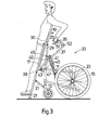
- the collapsible erection chair 10 shown in Figures 1 to 3 consists in a conventional manner of the support frame 11 with a pair of front wheels 13 and a pair of rear wheels 15, a seat 17 hinged to the support frame 11, a backrest 19 hinged to the seat 17 and one at the front of the seat articulated footrest 21.
- the support frame 11 consists of two side frames 23 which are connected to one another with two collapsible struts 25. Another strut 25 is provided for the backrest 19.
- the uprighting movement from the position in FIG. 1 to the position in FIG. 2 is supported by two springs 27. These springs 27 exert a force when erected on the seat, which counteracts the weight of the user.
- a parallelogram rod 29, which is rotatably attached at one end to the support frame 11 and at the other end to a pivot point 30 of the backrest 19, ensures that the backrest is practically the same in every position of the chair Takes position.
- the connecting lever 31 ensures the stabilization of the footrest 21.
- the erection chair has an adjustment device 33 on at least one side, but preferably on both sides, with which the respective handle 35 can be brought to different heights. This enables the user to bring the handles 35 to a height that is adapted to their own position and in which they can rest well on these handles 35 in order to continue to stand up.
- the handles 35 can also be brought into a lower position in which they are located in the vicinity of the rear wheels. In this position there are no obstacles to a lateral transfer movement of the user, as is desired, for example, when changing to a toilet seat.
- a closer look at the adjusting device 33 shows that it is articulated on the same axis of rotation 39 as the seat 17 on the support frame 11. This articulation at the front of the support frame enables the lowering of the support arms 37 with the handles 35 shown in FIG. 1 into a position in which they do not interfere with a transfer movement.
- a locking lever 41 is articulated at 40 on the support arm 37 at a distance from the pivot point 39.
- This has a slot 43 with four locking points 45, in which a locking member 47 arranged on the support frame 11 can engage.
- This locking lever 41 has two arms, the upper arm 49 forming a handle for unlocking the locking lever. If the user of the chair wants to lower the handle 35, he pushes the locking lever handle 49 forward so that the catch member 47 disengages and the handle 35 can be pushed into the position shown in Figure 1.
- Figures 2, 4 and 5 show the handles 35 in an outwardly pivoted position. Since the space between the rear wheels 15 and the seat 17 is limited, the handles 35 can be pivoted in the direction of the arrow 36 (FIG. 5) until they lie in the same vertical plane as the support arms 37. In this position, the handles are located 35 also in the position shown in Figure 1.
- the support arm 37 consists of a tube piece.
- the handle 35 has an extension 36 which engages in the free end of the pipe section and can be rotated therein about a predetermined range.
- the handle 35 has an actuating lever 51 which can be easily reached by the user's fingers and which is connected via a Bowden cable 52 to a blocking device 53 for the seat 17. In the unactuated position of the lever 51, the seat 17 remains blocked in the respective position.
- the user of the upright chair wants to move from the sitting position of FIG. 1 to the standing position of FIG. 3, he slightly raises the handles 35 and then rests on them.
- the handles 35 then pivot by rotation in the bushing 50 into the end position shown in FIGS. 2 and 5.
- the locking member 47 snaps into a locking point 45 of the locking lever 41.
- the user unblocks the seat by actuating the actuating lever 51 and is supported on the handles 35, it can he can move upwards with little effort thanks to the help of the springs 27. He then releases the actuating lever 51 and pulls the handles 35 further up until the latching members 47 snap in another position.
- the user then actuates the actuating lever 51 again and continues to move upward through the muscular strength of the arms until he has reached the desired position.
- the user again actuates the actuation lever 51, whereupon the seat 17 moves downward under the weight of the user.
- the locking levers 41 can be released and the handles 35 can be lowered by moving the locking element handles 49 forward.
- FIG. 6 shows another embodiment of the adjustment device 33.
- a ratchet wheel 55 or a ratchet segment is fixedly attached to the support frame 11, into which a locking pawl 57 movably arranged on the support arm 37 can engage. If the support arm 37 is moved upward, a downward movement is blocked by the pawl 57. In order to release the pawl, however, it can be moved upwards against the force of a spring 59 with the button 61. If necessary, the arm 63 can be moved transversely into a slot 65 and locked there.
- FIG. 7 shows an erection chair as in FIG. 3, but with a different adjustment device 33.
- the respective handle 35 is arranged on a column 63 which is mounted on the support frame 11 in an extendable manner.
- the handle 35 can be pulled up into any position, in which case a mechanism prevents the column 63 from sliding down. However, if the column is pulled out into the upper end position, it can be applied by applying slight pressure be brought back to the lower end position.
- the mechanism used for this purpose can be seen in Figure 8.
- the column 63 with the handle 35 and the actuating lever 51 is displaceable in the tube 65.
- a conical spring washer 67 clamps when a force acts on the handle 35 downward. However, the handle 35 can be pulled up further.
- the spring washer 67 gets into the space 69 and then the handle 35 is pressed down, the spring washer is turned inside out and the handle 35 can be moved downward with ease. If the spring washer 67 then enters the space 71, when the column 63 is pulled out it is again turned into the position shown in FIG. 8, in which it counteracts a downward movement of the column 63.
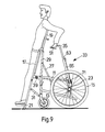
- FIGS. 9 and 10 differs from that of FIGS. 7 and 8 in that the tube 65 with the extendable column 63 is not arranged rigidly but pivotably at 71 on the rear of the supporting frame.
- a pawl mechanism not shown, similar to that of Figure 6, allows the column 63 to be locked in various pivot positions. To release the column again, simply pull button 73 to release the pawl. Instead of a linkage at 71, a linkage at the front on the support frame 11 would also be possible.
- the adjusting device 33 is constructed in the same way as that in FIGS. 7 and 8, so that reference can be made to the description there for details.
Landscapes
- Health & Medical Sciences (AREA)
- Life Sciences & Earth Sciences (AREA)
- Animal Behavior & Ethology (AREA)
- General Health & Medical Sciences (AREA)
- Public Health (AREA)
- Veterinary Medicine (AREA)
- Special Chairs (AREA)
- Chairs For Special Purposes, Such As Reclining Chairs (AREA)
Abstract
Der Aufrichtsrollstuhl besteht im wesentlichen aus einem Traggestell (11) mit den Rädern (13 und 15) und dem am Traggestell (11) angelenkten Sitz (17). Am Sitz (17) ist vorn eine Fußstütze (21) und hinten eine Rückenlehne (19) angelenkt. Eine Feder (27) übt zum Aufrichten eine Kraft aus, welche dem Gewicht des Benützers entgegenwirkt, um die Aufrichtbewegung zu erleichtern. Am Traggestell (11) ist an der Drehachse (39) auf beiden Seiten ein Tragarm (37) angelenkt, der in verschiedenen Stellungen arretierbar ist. Zu diesem Zweck weist der Verriegelungshebel (41) eine Anzahl von Raststellen (45) auf, in welche ein Rastglied (47) eingreifen kann. Wichtig ist, dass der Arm (37) in eine waagrechte Lage gebracht werden kann, in welcher er eine seitliche Transferbewegung des Benützers in der Sitzlage nicht hindert.The erection wheelchair essentially consists of a support frame (11) with the wheels (13 and 15) and the seat (17) articulated on the support frame (11). A footrest (21) is articulated to the seat (17) at the front and a backrest (19) at the rear. A spring (27) exerts a force for erecting which counteracts the weight of the user in order to facilitate the erecting movement. A support arm (37) is articulated on both sides of the support frame (11) on the axis of rotation (39) and can be locked in different positions. For this purpose, the locking lever (41) has a number of locking points (45) in which a locking element (47) can engage. It is important that the arm (37) can be brought into a horizontal position, in which it does not prevent the user from moving sideways in the sitting position.
Description
Die Erfindung betrifft einen Aufrichtstuhl, insbesondere einen zusammenfaltbaren Aufrichtrollstuhl, mit einem an einem Traggestell angeordneten Sitz, der aus einer Sitzstellung in eine Aufrichtstellung und umgekehrt beweglich ist, einer Vorrichtung, die auf den Sitz eine Kraft ausübt, um den Sitz dem Benützer nachzuführen und/oder dem Gewicht des Benützers entgegenzuwirken, um so die Aufrichtbewegung des Benützers zu erleichtern, und mindestens einem Handgriff, auf welchen der Benützer beim Aufrichten eine Kraft ausüben kann, um das auf den Sitz wirkende Gewicht zu verkleinern.The invention relates to an erection chair, in particular a foldable erection wheelchair, with a seat arranged on a support frame which can be moved from a seat position into an erection position and vice versa, a device which exerts a force on the seat in order to track the seat to the user and / or to counteract the weight of the user so as to facilitate the uprighting movement of the user, and at least one handle on which the user can exert a force when standing up to reduce the weight acting on the seat.
In der deutschen Offenlegungsschrift 23 62 029 wird eine Verstellvorrichtung zur Ausführung einer Kippbewegung bei einem Stuhl beschrieben. Diese Verstellvorrichtung besitzt zwei aus Gasfedern ausgeführte Hauptfedern, die je mit einem Ende am Sitz und mit dem anderen Ende am Traggestell befestigt sind. Vorn am Traggestell sind zwei vertikale Rohre vorgesehen, an denen sich je ein Handgriff mit einem Griffhebel befindet, wie sie beispielsweise an Fahrradlenkern üblich sind. Von diesen Griffhebeln führen Bowdenzüge zu Blockiereinrichtungen der Hauptfedern. Um sich mit diesem Aufrichtstuhl aufzurichten, löst der Benützer die Blockierung der Hauptfedern und neigt sich eventuell noch leicht nach vorn. Der Patient kann sich dabei noch an zwei Handgriffen, die vorn an zwei sich über die Sitzfläche erstreckenden vertikalen Rohren angebracht sind, festhalten und sich etwas nach vorn ziehen. Dabei wird durch die Federkraft der Sitz um seine Vorderkante nach oben verschwenkt und der Benützer in die Stehlage gebracht. An dieser Schwenkbewegung ist ausser den Hauptfedern noch eine Hilfsfeder beteiligt. Wenn nun der Benützer von der aufrechten Stellung wieder in die Sitzlage zurückkehren möchte, schwenkt er einen Handhebel, welcher die Hilfsfeder entspannt. Anschliessend werden die Hauptfedern unter dem Körpergewicht des Benützers wieder zusammengedrückt, so dass der Sitz wieder in die Sitzstellung zurückkehrt und nach Loslassen der entsprechenden Griffhebel in dieser Stellung blockiert wird. Durch Schwenken eines Betätigungshebels nach vorn kann der Benützer die Hilfsfeder wieder vorspannen, so dass deren zusätzliche Kraft wiederum für eine Aufrichtbewegung zur Verfügung steht.In the German laid-
Diese Art von Aufrichtstuhl ist verhältnismässig kompliziert und teuer in der Herstellung. Ein besonderer Nachteil besteht auch darin, dass die Handgriffe vorn am Stuhl angebracht sind und dadurch eine seitliche Transferbewegung des Benützers, wie sie beispielsweise zum Umsteigen auf den Toilettensitz erwünscht ist, verunmöglicht. Des weiteren befindet sich beim Aufstehen der Handgriff in einer ungünstigen Lage, so dass der Benützer es nur mit grossem Kraftaufwand, wenn überhaupt, fertigbringt, sich mit einem solchen Stuhl aufzurichten. Ein solcher Stuhl hat denn auch keine kommerzielle Verbreitung erfahren.This type of erection chair is relatively complicated and expensive to manufacture. A particular disadvantage is that the handles are attached to the front of the chair, making it impossible for the user to transfer laterally, as is desirable, for example, when changing to the toilet seat. Furthermore, the handle is in an unfavorable position when the user stands up, so that the user can only raise himself with such a chair with great effort, if at all. Such a chair has not been used commercially.
Es ist Aufgabe der vorliegenden Erfindung, einen Aufrichtstuhl, insbesondere einen zusammenlegbaren Aufrichtrollstuhl, zu verbessern. Die Handgriffe sollen eine seitliche Transferbewegung des Benützers in der Sitzlage nicht verhindern. Des weiteren sollten die Handgriffe in jeder Lage ergonometrisch richtig angeordnet sein, damit der Benützer ohne grossen Kraftaufwand eine Aufrichtbewegung vornehmen kann. Ferner sollten auch nicht zusätzliche teure Mechanismen und Gasfedern notwendig sein.It is an object of the present invention to improve an erection chair, in particular a collapsible erection wheelchair. The handles should not prevent a lateral transfer movement of the user in the sitting position. Furthermore, the handles should be arranged ergonomically in every position so that the user can perform an uprighting movement without great effort. Furthermore, additional expensive mechanisms and gas springs should not be necessary.
Gemäss der Erfindung wird dies bei einem Aufrichtstuhl der eingangs erwähnten Art dadurch erreicht, dass eine Verstellvorrichtung vorgesehen ist, um die Höhenlage des Handgriffes zu verstellen. Dies bringt gegenüber dem beschriebenen Stuhl gemäss dem Stand der Technik den Vorteil, dass der Benützer zum Aufstehen die Handgriffe in eine Lage bringen kann, in welcher er mit dem geringsten Aufwand eine Aufrichtbewegung einleiten kann. Versuche haben gezeigt, dass die beste Stellung der Handgriffe sich zu Beginn der Aufrichtbewegung in der Nähe des Benützers befindet, so dass der Benützer nur nach unten zu drücken braucht, um eine Aufrichtbewegung einzuleiten. Bewegt sich dann aber der Benützer ein Stück nach oben und nach vorn, so liegen die Handgriffe zu tief und zu weit hinten. Da aber die Handgriffe gemäss der Erfindung verstellbar sind, kann er diese nach einer gewissen Aufrichtbewegung nach oben in eine andere Stellung bringen, wo sie ihm wieder bequem liegen und er zur weiteren Aufrichtbewegung ohne grosse Anstrengung weiter Kraft auf die Handgriffe ausüben kann. Umgekehrt kann der Benützer beim Absitzen die Handgriffe wieder in eine tiefere Lage bringen, wo sie auch als Armauflage dienen können. Es ist aber auch möglich, die Handgriffe so weit abzusenken, so dass sie eine seitliche Transferbewegung in keiner Weise hindern. Zweckmässigerweise ist die Verstellvorrichtung durch einen Tragarm gebildet, der den Handgriff trägt, am Traggestell angelenkt und in verschiedenen Höhenlagen arretierbar ist. Dies ergibt eine besonders einfache und billige Ausbildung. Vorteilhaft ist der Tragarm in eine Stellung unterhalb des Niveaus des Sitzes versenkbar, auf welchem Niveau der Sitz sich in Sitzstellung befindet. Dies stellt sicher, dass die Handgriffe so abgesenkt werden können, dass sie eine Transferbewegung des Benützers in keiner Weise hindern.According to the invention, this is achieved in an erecting chair of the type mentioned at the outset in that an adjusting device is provided in order to adjust the height of the handle. This has the advantage over the described chair according to the prior art that the user can get the handles into a position in which he can initiate an uprighting movement with the least effort. Experiments have shown that the best position of the handles is in the vicinity of the user at the start of the uprighting movement, so that the user only needs to press down to initiate an uprighting movement. If the user then moves a bit upwards and forwards, the handles are too deep and too far back. However, since the handles are adjustable according to the invention, he can move them upwards to a different position after a certain uprighting movement, where they are comfortable again and he can continue to exert force on the handles for further uprighting movements without great effort. Conversely, when sitting down, the user can bring the handles back to a lower position, where they can also serve as an armrest. However, it is also possible to lower the handles so far that they do not in any way prevent a lateral transfer movement. The adjustment device is expediently formed by a support arm which carries the handle, is articulated on the support frame and can be locked at different heights. This results in a particularly simple and cheap training. The support arm can advantageously be lowered into a position below the level of the seat, at which level the seat is in the sitting position. This ensures that the handles can be lowered so that they do not in any way prevent the user from moving.
Es ist von besonderem Vorteil, wenn der jeweilige Tragarm vorn am Traggestell angelenkt ist. Der Tragarm kann dabei die gleiche Drehachse aufweisen wie der Sitz. Dadurch wird versichert, dass in jeder Stellung des Aufrichtstuhls die Handgriffe sich in einer für den Patienten bequemen Lage befinden. Wie der Sitz des Aufrichtstuhls sich bei einer Aufrichtbewegung nach oben und nach vorn bewegt, können dann auch die Handgriffe jeweils nach oben und nach vorn bewegt werden. Sie befinden sich daher immer in einer ergonometrisch günstigen Stellung. Es wäre aber auch möglich, den Tragarm hinten am Traggestell anzulenken, was den Vorteil hat, dass er auch in aufrechter Stellung eine Transferbewegung des Benützers gestattet.It is particularly advantageous if the respective support arm is articulated on the front of the support frame. The support arm can have the same axis of rotation as the seat. This ensures that the handles are in a comfortable position for the patient in any position of the erection chair. The handles can then be moved up and forwards as the seat of the upright chair moves up and forwards during an upright movement. You are therefore always in an ergonomically favorable position. However, it would also be possible to link the support arm to the rear of the support frame, which has the advantage that it also allows the user to transfer in an upright position.
Eine vorteilhafte Ausführungsform sieht vor, dass am Tragarm in Abstand von seinem Drehpunkt ein Verriegelungshebel ange-lenkt ist, der eine Vielzahl von Raststellen aufweist, in welche ein im Traggestell angeordnetes Rastglied eingreifen kann. Der Verriegelungshebel ist vorteilhaft zweiarmig, wobei der eine Arm die Raststellen und der andere Arm einen Griff zur Entriegelung aufweist. Dies ergibt eine besonders einfache Konstruktion der Verstelleinrichtung.An advantageous embodiment provides that a locking lever is g e-steered on the support arm at a distance from its fulcrum, which has a plurality of locking points into which a locking element arranged in the support frame can engage. The locking lever is advantageously two-armed, one arm having the locking points and the other arm having a handle for unlocking. This results in a particularly simple construction of the adjustment device.
Von besonderer Bedeutung ist, dass der jeweilige Handgriff um einen vorbestimmten Bereich verschwenkbar ist. Es ist nämlich zu beachten, dass ein Aufrichtrollstuhl einander widersprechende Erfordernisse zu erfüllen hat. Einerseits darf er eine gewisse Normbreite nicht überschreiten, weil sonst Probleme mit relativ schmalen Türöffnungen entstehen, und andererseits sollte der Sitz genügend breit sein, damit sich der Benützer wohlfühlt. Dies bedeutet aber, dass zwischen den Hinterrädern und dem Raum, der vom Sitz bei seiner Bewegung beansprucht wird, lediglich ein sehr schmaler Zwischenraum zur Verfügung steht. In diesem Zwischenraum muss der Handgriff für eine Transferbewegung abgesenkt werden können. Dank der erfindungsgemässen verschwenkbaren Ausbildung des Handgriffes ist dies möglich, ohne dass auf die übliche Sitzbreite verzichtet wird. Es genügt nämlich, zum Absenken der Handgriffe im Bereich der Räder die Handgriffe nach innen zu schwenken. Beim Stuhl gemäss dem eingangs beschriebenen Stand der Technik konnte eine Verminderung der Sitzbreite nur dadurch erzielt werden, dass die Handgriffe stationär vorn am Stuhl angebracht wurden. Dadurch wird aber eine seitliche Transferbewegung des Benützers verunmöglicht.It is particularly important that the respective handle can be pivoted through a predetermined range. It should be noted that an upright wheelchair must meet conflicting requirements. On the one hand, it must not exceed a certain standard width, otherwise problems with relatively narrow door openings arise, and on the other hand, the seat should be sufficiently wide so that the user feels comfortable. However, this means that there is only a very small space between the rear wheels and the space that the seat occupies when it moves. In this space, the handle must be able to be lowered for a transfer movement. Thanks to the pivotable design of the handle according to the invention, this is possible without sacrificing the usual seat width. It is sufficient to swivel the handles inwards in order to lower the handles in the area of the wheels. In the chair according to the prior art described at the outset, a reduction in the seat width could only be achieved by the handles being attached to the front of the chair in a stationary manner. This, however, makes a lateral transfer movement of the user impossible.
Zudem hat die stationäre Anordnung den vorher erwähnten Nachteil, dass sie vom Benützer viel Kraft für eine Aufrichtbewegung erfordert.In addition, the stationary arrangement has the previously mentioned disadvantage that it requires a lot of force from the user for an uprighting movement.
Eine zweckmässige Ausführungsform sieht vor, dass der jeweilige Tragarm eine Verriegelungsklinke aufweist, die normalerweise in ein am Traggestell fest angeordnetes Klinkenrad oder Klinkenradsegment eingreift, aber von Hand lösbar ist. Auch diese Konstruktion ergibt eine relativ billige Verstellvorrichtung. Es ist aber auch möglich, die Verstellvorrichtung durch eine am Traggestell ausziehbar gelagerte Säule zu bilden. Diese Konstruktion hat den Vorteil, dass sie keine verschwenkbaren Handgriffe benötigt.An advantageous embodiment provides that the respective support arm a Verriegelun g sklinke which the but is detachable from hand normally engages a fixedly arranged on the support frame ratchet wheel or ratchet segment. This construction also results in a relatively cheap adjustment device. However, it is also possible to form the adjusting device by means of a column which is mounted so as to be extendable on the supporting frame. The advantage of this construction is that it does not require any swiveling handles.
Es ist aber auch möglich, die Säule zusätzlich verschwenkbar auszugestelten und sie in verschiedenen Stellungen verriegelbar zu machen. Dabei befindet sich der Drehpunkt vorteilhaft hinten oder vorn am Traggestell.However, it is also possible to make the column additionally pivotable and to make it lockable in different positions. The pivot point is advantageously at the back or front of the support frame.
Wenn es auch möglich wäre, nur einen Handgriff vorzusehen, erweist es-sich doch als zweckmässig, auf jeder Seite des Sitzes einen Handgriff vorzusehen.Even if it were possible to provide only one handle, it proves to be expedient to provide a handle on each side of the seat.
Ausführungsbeispiele der Erfindung werden nun unter Bezugnahme auf die Zeichnung beschrieben. Es zeigt:
- Fig. 1 eine perspektivische Darstellung eines ersten Ausführungsbeispiels des erfindungsgemässen Aufrichtstuhls,
- Fig. 2 den Aufrichtstuhl von Fig. l, von hinten gesehen,
- Fig. 3 den Aufrichtstuhl von Figur 1 am Schluss der Aufrichtbewegung,
- Fig. 4 einen Handgriff mit Tragarm von der Seite gesehen,
- Fig. 4a eine besonders vorteilhafte Ausführungsform der Handgrifflagerung im Tragarm,
- Fig. 5 Handgriff mit Tragarm von oben gesehen,
- Fig. 6 ein Ausführungsbeispiel der Verstellvorrichtung für den Tragarm,
- Fig. 7 ein weiteres Ausführungsbeispiel eines Aufrichtstuhls mit einer anderen Verstellvorrichtung für den Handgriff,
- Fig. 8 eine detaillierte Darstellung der Verstellvorrichtung gemäss Figur 7,
- Fig. 9 ein weiteres Ausführungsbeispiel eines Aufrichtstuhls mit einer Verstellvorrichtung ähnlich wie in Figur 7, und
- Fig. 10 eine detaillierte Darstellung der Verstellvorrichtung von Fig. 8.
- 1 is a perspective view of a first embodiment of the erecting chair according to the invention,
- 2 the erection chair of FIG. 1, seen from behind,
- 3 the erection chair of FIG. 1 at the end of the erection movement,
- 4 seen a handle with a support arm from the side,
- 4a a particularly advantageous embodiment of the handle storage in the support arm,
- 5 handle with support arm seen from above,
- 6 shows an embodiment of the adjusting device for the support arm,
- 7 shows a further exemplary embodiment of an erecting chair with another adjusting device for the handle,
- 8 shows a detailed illustration of the adjusting device according to FIG. 7,
- 9 shows a further exemplary embodiment of an erecting chair with an adjusting device similar to that in FIG. 7, and
- FIG. 10 shows a detailed illustration of the adjusting device from FIG. 8.
Der in den Figuren 1 bis 3 dargestellte zusammenlegbare Aufrichtstuhl 10 besteht in herkömmlicher Weise aus dem Traggestell 11 mit einem Paar Vorderräder 13 und einem Paar Hinterräder 15, einem am Traggestell 11 angelenkten Sitz 17, einer am Sitz 17 angelenkten Rückenlehne 19 und einer vorn am Sitz angelenkten Fussauflage 21.The
Das Traggestell 11 besteht aus zwei Seitenrahmen 23, die mit zwei zusammenklappbaren Verstrebungen 25 miteinander verbunden sind. Eine weitere Verstrebung 25 ist für die Rückenlehne 19 vorgesehen.The
Die Aufrichtbewegung aus der Stellung von Figur 1 in die Stellung von Figur 2 wird durch zwei Federn 27 unterstützt. Diese Federn 27 üben beim Aufrichten auf den Sitz eine Kraft aus, welche dem Gewicht des Benützers entgegenwirkt. Eine Parallelogrammstange 29, die mit einem Ende am Traggestell 11 und mit dem anderen Ende an einer Anlenkstelle 30 der Rückenlehne 19 drehbar befestigt ist, sorgt dafür, dass die Rückenlehne in jeder Stellung des Stuhles praktisch die gleiche Lage einnimmt. In ähnlicher Weise sorgt der Verbindungshebel 31 für die Stabilisierung der Fussstütze 21.The uprighting movement from the position in FIG. 1 to the position in FIG. 2 is supported by two
Von Bedeutung ist nun, dass der Aufrichtstuhl mindestens auf einer Seite, vorzugsweise aber auf beiden Seiten, eine Verstellvorrichtung 33 aufweist, mit welcher der jeweilige Handgriff 35 in verschiedene Höhenlagen gebracht werden kann. Dies ermöglicht es dem Benützer, die Handgriffe 35 in eine Höhenlage zu bringen, die seiner eigenen Lage angepasst ist und in welcher er sich gut auf diese Handgriffe 35 abstützen kann, um sich weiter aufzurichten.It is important that the erection chair has an
Wie aber Figur 1 zeigt, können die Handgriffe 35 auch in eine untere Lage gebracht werden, in welcher sie sich in der Nähe der Hinterräder befinden. In dieser Lage bestehen keine Hindernisse für eine seitliche Transferbewegung des Benützers, wie sie beispielsweise zum Umsteigen auf einen Toilettensitz erwünscht ist.However, as FIG. 1 shows, the
Eine nähere Betrachtung der Verstellvorrichtung 33 zeigt, dass diese einen auf der gleichen Drehachse 39 wie der Sitz 17 am Traggestell 11 angelenkt ist. Diese Anlenkung vorn am Traggestell ermöglicht das in Figur 1 gezeigte Absenken der Tragarme 37 mit den Griffen 35 in eine Lage, in welcher sie eine Transferbewegung nicht stören.A closer look at the adjusting
Wie insbesondere aus Figur 3 ersichtlich ist, ist bei 40 am Traggarm 37 in einem Abstand vom Drehpunkt 39 ein Verriegelungshebel 41 angelenkt. Dieser besitzt einen Schlitz 43 mit vier Raststellen 45, in welche ein am Traggestell 11 angeordnetes Rastglied 47 eingreifen kann. Dieser Verriegelungshebel 41 ist zweiarmig, wobei der obere Arm 49 einen Griff zur Entriegelung des Verriegelungshebels bildet. Will der Benützer des Stuhles den Griff 35 absenken, drückt er den Verriegelungshebelgriff 49 nach vorn, so dass das Rastglied 47 ausklinkt und der Griff 35 in die in Figur 1 gezeigte Lage gestossen werden kann.As can be seen in particular from FIG. 3, a locking
Figuren 2, 4 und 5 zeigen die Handgriffe 35 in einer nach aussen verschwenkten Stellung. Da der Platz zwischen den Hinterrädern 15 und dem Sitz 17 beschränkt ist, sind die Handgriffe 35 in der Richtung des Pfeils 36 (Figur 5) soweit verschwenkbar, bis sie in der gleichen senkrechten Ebene liegen wie die Tragarme 37. In dieser Lage finden die Handgriffe 35 auch in der in Figur 1 gezeigten Stellung Platz.Figures 2, 4 and 5 show the
Nach dem Ausschwenken in die Gebrauchslage von Figur 2 besteht auch genügend Spielraum zwischen den Fingern des Benützers und dem Sitz 17, wenn sich dieser nach oben oder nach unten an den Handgriffen 35 vorbeibewegt.After swiveling out into the position of use of FIG. 2, there is also sufficient scope between the fingers of the user and the
Bei der Ausführungsform von Fig. 4a besteht der Tragarm 37 aus einem Rohrstück. Der Handgriff 35 weist einen Fortsatz 36 auf, der in das freie Ende des Rohrstücks eingreift und in diesem um einen vorbestimmten Bereich drehbar ist.In the embodiment of Fig. 4a, the
Wie aus den Figuren 1 und 4 ersichtlich ist, befindet sich beim Handgriff 35 ein von den Fingern des Benützers leicht erreichbarer Betätigungshebel 51, der über einen Bowdenzug 52 mit einer Blockiervorrichtung 53 für den Sitz 17 verbunden ist. In der unbetätigten Stellung des Hebels 51 bleibt der Sitz 17 in der jeweiligen Lage blockiert.As can be seen from FIGS. 1 and 4, the
Wenn der Benützer des Aufrichtstuhls sich aus der Sitzlage von Figur 1 in die Stehlage von Figur 3 begeben will, so hebt er die Handgriffe 35 leicht an und stützt sich dann auf diese ab. Dabei schwenken dann die Griffe 35 durch Drehung in der Buchse 50 in die in den Figuren 2 und 5 gezeichnete Endstellung. Ferner rastet das Rastglied 47 in eine Raststelle 45 des Verriegelungshebels 41 ein. Wenn nun der Benützer durch Betätigung des Betätigungshebels 51 den Sitz deblockiert und sich auf die Griffe 35 abstützt, so kann er sich mit geringem Kraftaufwand dank der Hilfe der Federn 27 nach oben bewegen. Er lässt dann den Betätigungshebel 51 los und zieht die Griffe 35 weiter nach oben bis die Rastglieder 47 in einer anderen Stellung einrasten. Der Benützer betätigt dann wiederum den Betätigungshebel 51 und bewegt sich durch die Muskelkraft der Arme weiter nach oben, bis er die gewünschte Stellung erreicht hat.If the user of the upright chair wants to move from the sitting position of FIG. 1 to the standing position of FIG. 3, he slightly raises the
Um den Stuhl abzusenken betätigt der Benützer wiederum die Betätigungshebel 51, worauf sich der Sitz 17 unter dem Gewicht des Benützers nach unten bewegt. Durch eine Bewegung der Rastgliedgriffe 49 nach vorn können die Rasthebel 41 gelöst und die Griffe 35 abgesenkt werden.In order to lower the chair, the user again actuates the
Figur 6 zeigt eine andere Ausführungsform der Verstellvorrichtung 33. Am Traggestell 11 ist ein Klinkenrad 55 oder ein Klinkensegment fest angebracht, in welches eine am Tragarm 37 beweglich angeordnete Verriegelungsklinke 57 eingreifen kann. Wird der Tragarm 37 nach oben bewegt, so wird eine Bewegung nach unten durch die Klinke 57 blockiert. Um die Klinke zu lösen, kann sie jedoch entgegen der Kraft einer Feder 59 mit dem Knopf 61 nach oben bewegt werden. Gegebenenfalls kann der Arm 63 quer in einen Schlitz 65 bewegt und dort arretiert werden.FIG. 6 shows another embodiment of the
Figur 7 zeigt einen Aufrichtstuhl wie in Figur 3, jedoch mit einer anderen Verstellvorrichtung 33. Bei dieser Verstellvorrichtung 33 ist der jeweilige Handgriff 35 an einer am Traggestell;.11 ausziehbar gelagerten Säule 63 angeordnet. Der Handgriff 35 kann in eine beliebige Stellung heraufgezogen werden, wobei dann ein Mechanismus die Säule 63 am hinuntergleiten hindert. Wird jedoch die Säule in die obere Endstellung hinausgezogen, so kann sie durch geringen Druck wieder in die untere Endstellung gebracht werden. Der für diesen Zweck verwendete Mechanismus ist in Figur 8 ersichtlich. Die Säule 63 mit dem Handgriff 35 und dem Betätigungshebel 51 ist im Rohr 65 verschiebbar. Eine konische Federscheibe 67 bewirkt ein Festklemmen, wenn eine Kraft auf den Griff 35 nach unten wirkt. Der Griff 35 kann jedoch weiter nach oben gezogen werden. Wenn die Federscheibe 67 in den Raum 69 gelangt, und dann der Griff 35 nach unten gedrückt wird, so wird die Federscheibe umgestülpt und der Griff 35 lässt sich mühelos nach unten bewegen. Gelangt dann die Federscheibe 67 in den Raum 71, so wird sie beim Herausziehen der Säule 63 wiederum in die in Figur 8 gezeichnete Lage gestülpt, in welcher sie einer Abwärtsbewegung der Säule 63 entgegenwirkt.FIG. 7 shows an erection chair as in FIG. 3, but with a
Das in den Figuren 9 und 10 gezeigte Ausführungsbeispiel eines Aufrichtstuhls unterscheidet sich von jenem der Figuren 7 und 8 dadurch, dass das Rohr 65 mit der ausziehbaren Säule 63 nicht starr sondern bei 71 verschwenkbar hinten am Tragrahmen angeordnet ist. Ein nicht dargestellter Klinkenmechanismus, ähnlich jenem von Figur 6, gestattet es, die Säule 63 in verschiedenen Schwenkstellungen zu blockieren. Um die Säule wieder zu lösengenügt es, am Knopf 73 zu ziehen und damit die Klinke zu lösen. Statt einer Anlenkung bei 71 wäre auch eine Anlenkung vorn am Traggestell 11 möglich. Im übrigen ist die Verstellvorrichtung 33 gleich aufgebaut wie jene in den Figuren 7 und 8, so dass für Einzelheiten auf die dortige Beschreibung verwiesen werden kann.The exemplary embodiment of an erection chair shown in FIGS. 9 and 10 differs from that of FIGS. 7 and 8 in that the
Claims (17)
Applications Claiming Priority (2)
| Application Number | Priority Date | Filing Date | Title |
|---|---|---|---|
| CH174484 | 1984-04-06 | ||
| CH1744/84 | 1984-04-06 |
Publications (3)
| Publication Number | Publication Date |
|---|---|
| EP0159562A2 true EP0159562A2 (en) | 1985-10-30 |
| EP0159562A3 EP0159562A3 (en) | 1986-10-08 |
| EP0159562B1 EP0159562B1 (en) | 1988-12-28 |
Family
ID=4217567
Family Applications (1)
| Application Number | Title | Priority Date | Filing Date |
|---|---|---|---|
| EP85103664A Expired EP0159562B1 (en) | 1984-04-06 | 1985-03-27 | Lifting chair |
Country Status (5)
| Country | Link |
|---|---|
| US (1) | US4598944A (en) |
| EP (1) | EP0159562B1 (en) |
| JP (1) | JPS60225555A (en) |
| DE (1) | DE3566951D1 (en) |
| FR (1) | FR2562420B3 (en) |
Cited By (9)
| Publication number | Priority date | Publication date | Assignee | Title |
|---|---|---|---|---|
| GB2293797A (en) * | 1994-10-06 | 1996-04-10 | Pennington Richards Cyril Mont | Wheelchair with a forward tilting or reclining seat, fixed front and castored rear wheels. |
| GB2296901A (en) * | 1995-01-13 | 1996-07-17 | John Hyde Taylor | Patient handling hoist and chair comprising a parallelogram linkage on a wheeled frame. |
| EP0815822A1 (en) * | 1996-06-27 | 1998-01-07 | Levo AG Dottikon | Stand-up wheelchair |
| NL2002681C2 (en) * | 2009-03-27 | 2010-09-28 | Deprofundis B V | ASSISTANT DEVICE TO BE ADDED TO A WHEELCHAIR WITH STEP AID AND STABILIZERS, AND A WHEELCHAIR INTEGRATED. |
| US8870216B2 (en) | 2011-09-20 | 2014-10-28 | Dane Technologies, Inc. | Stabilized raising wheelchair |
| US9375372B2 (en) | 2010-04-27 | 2016-06-28 | Levo Ag Wohlen | Stand-up unit for stand-up wheelchairs and chairs, particularly therapy chairs |
| CN106029033A (en) * | 2015-01-29 | 2016-10-12 | 法兰西床株式会社 | Wheel chair |
| US9775753B2 (en) | 2013-05-17 | 2017-10-03 | Dane Technologies, Inc. | Methods, systems, and devices relating to multifunctional aircraft aisle wheelchair |
| CN112716708A (en) * | 2021-02-24 | 2021-04-30 | 海南大学 | Multifunctional lifting-assisting wheelchair |
Families Citing this family (53)
| Publication number | Priority date | Publication date | Assignee | Title |
|---|---|---|---|---|
| GB2183150A (en) * | 1985-09-26 | 1987-06-03 | Cluney Upholstery Limited | Chair |
| US5137102A (en) * | 1986-08-25 | 1992-08-11 | Retec Pr, Inc. | Combination wheelchair and walker apparatus |
| US4929022A (en) * | 1989-02-23 | 1990-05-29 | Alexander Geraci | Chair having lift apparatus |
| US4948156A (en) * | 1989-03-13 | 1990-08-14 | Legg-On | Standing lift and support for wheelchair user |
| US5195803A (en) * | 1989-06-21 | 1993-03-23 | Invacare Corporation | Reclining seat back assembly for a wheelchair |
| US4968051A (en) * | 1989-12-12 | 1990-11-06 | Luo Chung I | Trigger activated device for adjusting the inclination of a back frame of a wheelchair |
| US5401044A (en) * | 1990-05-23 | 1995-03-28 | Regain, Inc. | Two piece collapsible wheelchair |
| US5609348A (en) * | 1990-05-23 | 1997-03-11 | Regain, Inc. | Wheelchair |
| US5211414A (en) * | 1990-05-23 | 1993-05-18 | Regain, Inc. | Wheelchair |
| DE4141158A1 (en) * | 1991-05-06 | 1992-11-12 | Rainer Dipl Ing Scholl | WHEELCHAIR, ESPECIALLY FOR CROSS-LID PEOPLE |
| FR2695554B1 (en) * | 1992-09-15 | 1994-12-23 | Int Diffusion Consomma | Motorized assistance device, adaptable to a lift chair and lift chair by applying. |
| US5379866A (en) * | 1993-07-20 | 1995-01-10 | Genesis Composites, Inc. | Light-weight wheel assembly and static brake for wheelchairs |
| US5603520A (en) * | 1993-07-20 | 1997-02-18 | Teksourc, Lc | Light-weight wheel assembly for wheelchairs |
| US5667235A (en) * | 1993-07-27 | 1997-09-16 | Teksource, Lc | Multi-adjustable wheelchair |
| US5769442A (en) * | 1994-01-31 | 1998-06-23 | Teksource, Hlc | Structural shell frames and method of making same |
| US5411044A (en) * | 1994-04-12 | 1995-05-02 | Andolfi; Alexander S. | Patient transfer walker |
| US5503773A (en) * | 1994-09-08 | 1996-04-02 | Genesis Composites, L.C. | Method of making a composite handlebar |
| US5984411A (en) * | 1995-09-11 | 1999-11-16 | Galumbeck; Michael H. | Elevator chair |
| US6454285B1 (en) * | 2000-03-21 | 2002-09-24 | Larry Koenig | Ergonomic wheelchair with patient lifting mechanism |
| GB2366854A (en) * | 2000-09-15 | 2002-03-20 | Cummins Engine Co Ltd | Vehicle seat with joystick control |
| US6425634B1 (en) * | 2001-01-19 | 2002-07-30 | Cliffard Romero | Assist apparatus for patients in a wheelchair |
| US6431650B1 (en) | 2001-01-26 | 2002-08-13 | Jeremy D. Visone | Height adjustable wheelchair apparatus |
| US6619681B2 (en) | 2001-05-16 | 2003-09-16 | Delano Association For The Developmentally Disabled | Dynamic seating and walking wheelchair |
| WO2003082410A1 (en) * | 2002-04-03 | 2003-10-09 | Oga Co., Ltd | Exercise assisting machine |
| ITPD20020273A1 (en) * | 2002-10-22 | 2004-04-23 | Vassilli Srl | MANUAL DISABLED WHEELCHAIR WITH HEIGHT-ADJUSTABLE SEAT. |
| US6976698B2 (en) * | 2003-04-24 | 2005-12-20 | Rehabilitation Institute Of Chicago | Manually operable standing wheelchair |
| SE522825C2 (en) * | 2003-05-05 | 2004-03-09 | Arjo Hospital Equipment Ab | Patient chair has chassis and undercarriage, with seat arrangement connected to chassis for patient, drive being provided for moving seat arrangement in height direction relatively to undercarriage |
| FR2856280B1 (en) * | 2003-06-19 | 2006-02-10 | Lifestand Internat Sa | VERTICALIZING ARMCHAIR WITH ADJUSTABLE HANDLES |
| FR2856486B1 (en) | 2003-06-19 | 2005-11-04 | Lifestand Internat Sa | MULTIPROOF HANDLE AND VERTICALIZING ARMCHAIR WHILE APPLYING |
| FR2856281B1 (en) * | 2003-06-19 | 2006-02-17 | Lifestand Internat Sa | VERTICALIZING ARMCHAIR EQUIPPED WITH MEANS FOR NEUTRALIZING THE VERTICALIZATION-LOWERING CONTROL |
| US7097189B2 (en) * | 2003-11-18 | 2006-08-29 | Lloyd Linden, Inc. | Wheelchair with self-raising seat |
| FR2870451B1 (en) * | 2004-05-24 | 2006-08-18 | Lifestand Internat Sa | VERTICALIZING ARMCHAIR WITH DEMULTIPLICATION OF THE VERTICALIZATION MANEUVER |
| JP2008514243A (en) * | 2004-08-16 | 2008-05-08 | クレイマー,ケネス,エル. | Home care system |
| AU2005277594A1 (en) | 2004-08-16 | 2006-03-02 | Hill-Rom Services, Inc. | Chair |
| CA2601470C (en) | 2005-03-30 | 2014-09-23 | Jaimie Borisoff | A height adjustable wheelchair |
| US20060284462A1 (en) * | 2005-06-15 | 2006-12-21 | Cheng Yu W | Medical chair |
| GB0609315D0 (en) * | 2006-05-11 | 2006-06-21 | Technicon Internat Man Service | Improved seat |
| GB0610313D0 (en) * | 2006-05-24 | 2006-07-05 | Firth Charles B | Wheelchair with elevating seat |
| US7686319B1 (en) * | 2006-05-31 | 2010-03-30 | Robert M Fink | Double amputee conveyance |
| WO2008150301A1 (en) * | 2007-06-01 | 2008-12-11 | Ghn Technologies, Llc | Chair device |
| US7896385B2 (en) * | 2007-09-21 | 2011-03-01 | Michael Every | Foldable wheelchair |
| US20110031787A1 (en) * | 2009-08-10 | 2011-02-10 | Bounds Steven R | Get a grip grab handle |
| EP2525759B1 (en) | 2010-01-20 | 2017-12-20 | The UAB Research Foundation | Transport chairs |
| US10426677B2 (en) | 2010-01-20 | 2019-10-01 | The Uab Research Foundation | Reclining transport chairs |
| US8360518B2 (en) * | 2010-09-27 | 2013-01-29 | David Braaten | Wheelchair lift assist mechanism |
| US9101520B2 (en) * | 2011-11-04 | 2015-08-11 | The United States of America, as Represented by the Department of Veterans Affair | Mobile manual standing wheelchair |
| US9044369B2 (en) * | 2011-11-04 | 2015-06-02 | The United States Of America, As Represented By The Department Of Veterans Affairs | Mobile manual standing wheelchair |
| DE202014010504U1 (en) | 2014-02-03 | 2016-01-05 | Dagmar Heuer | Wheelchair for guidance on both sides |
| EP3310314B1 (en) | 2015-06-19 | 2022-10-26 | Senior Life LLC | Lift-assist chair |
| FR3063008B1 (en) | 2017-02-21 | 2022-03-18 | Marc Bardgett | WALKING AID WHEELCHAIR |
| EP4346531A1 (en) | 2021-06-03 | 2024-04-10 | Home Furnishings Resource Group Inc. D/B/A F3 | Lift assist device for a bathroom |
| US11963921B2 (en) | 2022-07-08 | 2024-04-23 | Leo Harden | Convertible walker |
| US11633322B1 (en) | 2022-07-08 | 2023-04-25 | Leo Harden | Convertible wheelchair |
Citations (2)
| Publication number | Priority date | Publication date | Assignee | Title |
|---|---|---|---|---|
| DE2362029A1 (en) | 1972-12-13 | 1974-06-20 | Deucher Conrad R | ADJUSTMENT DEVICE, IN PARTICULAR FOR THE PERFORMANCE OF A TILTING MOVEMENT OF THE SEAT OF A SICK CHAIR OR THE HEAD OR. FOOTBOARD OF A BED |
| GB1534777A (en) | 1976-04-30 | 1978-12-06 | Imbro M | Invalid chairs |
Family Cites Families (9)
| Publication number | Priority date | Publication date | Assignee | Title |
|---|---|---|---|---|
| US2433969A (en) * | 1945-01-30 | 1948-01-06 | Chester F Wood | Invalid's vehicle |
| CH473579A (en) * | 1965-04-09 | 1969-06-15 | Carl Udden Per Edvard | Mobile chair with foot and arm rests |
| DE2120382A1 (en) * | 1970-04-29 | 1971-12-02 | Korpela, Viljo Gunnar, Helsinki | Arrangement for wheelchairs |
| GB1407033A (en) * | 1972-06-19 | 1975-09-24 | Godfrey Eng Ltd | Standing aid |
| DE2259383A1 (en) * | 1972-12-05 | 1974-06-12 | Werner Last | UNIVERSAL AND TRAINING DEVICE FOR WHEELCHAIR USERS |
| CH588860A5 (en) * | 1975-06-03 | 1977-06-15 | Valutec Ag | |
| CH608186A5 (en) * | 1976-01-30 | 1978-12-29 | Valutec Ag | |
| CH632153A5 (en) * | 1981-12-14 | 1982-09-30 | Deucher Conrad R | Erecting chair |
| CH653857A5 (en) * | 1984-10-22 | 1986-01-31 | Valutec Ag | Erecting chair |
-
1985
- 1985-03-27 EP EP85103664A patent/EP0159562B1/en not_active Expired
- 1985-03-27 DE DE8585103664T patent/DE3566951D1/en not_active Expired
- 1985-04-01 US US06/718,079 patent/US4598944A/en not_active Expired - Fee Related
- 1985-04-02 JP JP60068617A patent/JPS60225555A/en active Granted
- 1985-04-05 FR FR8505225A patent/FR2562420B3/en not_active Expired
Patent Citations (2)
| Publication number | Priority date | Publication date | Assignee | Title |
|---|---|---|---|---|
| DE2362029A1 (en) | 1972-12-13 | 1974-06-20 | Deucher Conrad R | ADJUSTMENT DEVICE, IN PARTICULAR FOR THE PERFORMANCE OF A TILTING MOVEMENT OF THE SEAT OF A SICK CHAIR OR THE HEAD OR. FOOTBOARD OF A BED |
| GB1534777A (en) | 1976-04-30 | 1978-12-06 | Imbro M | Invalid chairs |
Cited By (15)
| Publication number | Priority date | Publication date | Assignee | Title |
|---|---|---|---|---|
| GB2293797B (en) * | 1994-10-06 | 1998-05-06 | Pennington Richards Cyril Mont | Wheelchair |
| GB2293797A (en) * | 1994-10-06 | 1996-04-10 | Pennington Richards Cyril Mont | Wheelchair with a forward tilting or reclining seat, fixed front and castored rear wheels. |
| GB2296901A (en) * | 1995-01-13 | 1996-07-17 | John Hyde Taylor | Patient handling hoist and chair comprising a parallelogram linkage on a wheeled frame. |
| EP0815822A1 (en) * | 1996-06-27 | 1998-01-07 | Levo AG Dottikon | Stand-up wheelchair |
| US5984338A (en) * | 1996-06-27 | 1999-11-16 | Levo Ag Dottikon | Lightweight stabilized raising chair |
| NL2002681C2 (en) * | 2009-03-27 | 2010-09-28 | Deprofundis B V | ASSISTANT DEVICE TO BE ADDED TO A WHEELCHAIR WITH STEP AID AND STABILIZERS, AND A WHEELCHAIR INTEGRATED. |
| US9375372B2 (en) | 2010-04-27 | 2016-06-28 | Levo Ag Wohlen | Stand-up unit for stand-up wheelchairs and chairs, particularly therapy chairs |
| US8870216B2 (en) | 2011-09-20 | 2014-10-28 | Dane Technologies, Inc. | Stabilized raising wheelchair |
| US9351891B2 (en) | 2011-09-20 | 2016-05-31 | Dane Technologies, Inc. | Stabilized raising wheelchair |
| US9775753B2 (en) | 2013-05-17 | 2017-10-03 | Dane Technologies, Inc. | Methods, systems, and devices relating to multifunctional aircraft aisle wheelchair |
| CN106029033A (en) * | 2015-01-29 | 2016-10-12 | 法兰西床株式会社 | Wheel chair |
| EP3251649A4 (en) * | 2015-01-29 | 2018-09-12 | France Bed Co., Ltd. | Wheel chair |
| CN106029033B (en) * | 2015-01-29 | 2020-04-03 | 法兰西床株式会社 | Wheel chair |
| CN112716708A (en) * | 2021-02-24 | 2021-04-30 | 海南大学 | Multifunctional lifting-assisting wheelchair |
| CN112716708B (en) * | 2021-02-24 | 2023-04-25 | 海南大学 | Multifunctional lifting-assisting wheelchair |
Also Published As
| Publication number | Publication date |
|---|---|
| JPS60225555A (en) | 1985-11-09 |
| DE3566951D1 (en) | 1989-02-02 |
| FR2562420B3 (en) | 1986-03-28 |
| FR2562420A3 (en) | 1985-10-11 |
| EP0159562A3 (en) | 1986-10-08 |
| EP0159562B1 (en) | 1988-12-28 |
| US4598944A (en) | 1986-07-08 |
| JPH035175B2 (en) | 1991-01-24 |
Similar Documents
| Publication | Publication Date | Title |
|---|---|---|
| EP0159562B1 (en) | Lifting chair | |
| DE69820357T2 (en) | Adjustable high chair | |
| DE69200019T2 (en) | Wheelchair. | |
| DE2931107A1 (en) | FOOTREST LOCK FOR A WHEELCHAIR | |
| DE3309174C1 (en) | Bed side part | |
| DE19945118A1 (en) | Chair adjustable to various positions | |
| DE3619944A1 (en) | Arm rest associated with the backrest of a motor-vehicle seat | |
| DE1290297C2 (en) | SUPPORT FOR A DENTAL FLOATING TABLE | |
| DE1429413C3 (en) | Fitting for an armchair that can be adjusted in several positions | |
| DE3249163C2 (en) | ||
| DE69013586T2 (en) | Wheelchair. | |
| DE4123405C1 (en) | Support and lift handle for wheelchair user - has rung set with horizontal rungs in use, with lowermost one as support and topmost one as lifting aid | |
| EP0004282B1 (en) | Hospital bed | |
| DE4414608C2 (en) | Vehicle seat, in particular motor vehicle rear seat | |
| DE2165209B2 (en) | Bed, especially sick bed | |
| DE3435575A1 (en) | Collapsible undercarriage | |
| DE2540054A1 (en) | Adjustable back with adjuster tube for wheelchair - allowing easy actuation by invalid without uncomfortable position | |
| DE2365905C3 (en) | Rocking chair | |
| DE20000612U1 (en) | Seating | |
| DE3412755A1 (en) | Extendable running gear for a standing body | |
| DE3151954C2 (en) | Adjustable passenger seat for a motor vehicle, in particular an ambulance | |
| DE3322587C1 (en) | Length-adjustable leg support for a wheelchair for an invalid | |
| DE1429315C (en) | Sofa bed | |
| DE9406942U1 (en) | Telescopic ladder | |
| DE3129377A1 (en) | Lying and/or seating furniture, especially hospital bed or hospital chair |
Legal Events
| Date | Code | Title | Description |
|---|---|---|---|
| PUAI | Public reference made under article 153(3) epc to a published international application that has entered the european phase |
Free format text: ORIGINAL CODE: 0009012 |
|
| AK | Designated contracting states |
Designated state(s): CH DE FR GB IT LI NL SE |
|
| PUAL | Search report despatched |
Free format text: ORIGINAL CODE: 0009013 |
|
| AK | Designated contracting states |
Kind code of ref document: A3 Designated state(s): CH DE FR GB IT LI NL SE |
|
| 17P | Request for examination filed |
Effective date: 19860908 |
|
| 17Q | First examination report despatched |
Effective date: 19871207 |
|
| GRAA | (expected) grant |
Free format text: ORIGINAL CODE: 0009210 |
|
| AK | Designated contracting states |
Kind code of ref document: B1 Designated state(s): CH DE FR GB IT LI NL SE |
|
| ITF | It: translation for a ep patent filed | ||
| REF | Corresponds to: |
Ref document number: 3566951 Country of ref document: DE Date of ref document: 19890202 |
|
| GBT | Gb: translation of ep patent filed (gb section 77(6)(a)/1977) | ||
| ET | Fr: translation filed | ||
| PLBE | No opposition filed within time limit |
Free format text: ORIGINAL CODE: 0009261 |
|
| STAA | Information on the status of an ep patent application or granted ep patent |
Free format text: STATUS: NO OPPOSITION FILED WITHIN TIME LIMIT |
|
| 26N | No opposition filed | ||
| ITTA | It: last paid annual fee | ||
| PGFP | Annual fee paid to national office [announced via postgrant information from national office to epo] |
Ref country code: SE Payment date: 19930223 Year of fee payment: 9 |
|
| PGFP | Annual fee paid to national office [announced via postgrant information from national office to epo] |
Ref country code: GB Payment date: 19930224 Year of fee payment: 9 |
|
| PGFP | Annual fee paid to national office [announced via postgrant information from national office to epo] |
Ref country code: FR Payment date: 19930329 Year of fee payment: 9 |
|
| PGFP | Annual fee paid to national office [announced via postgrant information from national office to epo] |
Ref country code: DE Payment date: 19930330 Year of fee payment: 9 |
|
| PGFP | Annual fee paid to national office [announced via postgrant information from national office to epo] |
Ref country code: NL Payment date: 19930331 Year of fee payment: 9 |
|
| PGFP | Annual fee paid to national office [announced via postgrant information from national office to epo] |
Ref country code: CH Payment date: 19930405 Year of fee payment: 9 |
|
| PG25 | Lapsed in a contracting state [announced via postgrant information from national office to epo] |
Ref country code: GB Effective date: 19940327 |
|
| PG25 | Lapsed in a contracting state [announced via postgrant information from national office to epo] |
Ref country code: SE Free format text: LAPSE BECAUSE OF NON-PAYMENT OF DUE FEES Effective date: 19940328 |
|
| PG25 | Lapsed in a contracting state [announced via postgrant information from national office to epo] |
Ref country code: LI Effective date: 19940331 Ref country code: CH Effective date: 19940331 |
|
| PG25 | Lapsed in a contracting state [announced via postgrant information from national office to epo] |
Ref country code: NL Effective date: 19941001 |
|
| NLV4 | Nl: lapsed or anulled due to non-payment of the annual fee | ||
| GBPC | Gb: european patent ceased through non-payment of renewal fee |
Effective date: 19940327 |
|
| PG25 | Lapsed in a contracting state [announced via postgrant information from national office to epo] |
Ref country code: FR Effective date: 19941130 |
|
| REG | Reference to a national code |
Ref country code: CH Ref legal event code: PL |
|
| PG25 | Lapsed in a contracting state [announced via postgrant information from national office to epo] |
Ref country code: DE Effective date: 19941201 |
|
| REG | Reference to a national code |
Ref country code: FR Ref legal event code: ST |
|
| EUG | Se: european patent has lapsed |
Ref document number: 85103664.0 Effective date: 19941010 |