EP2409675B1 - Actuation device for a turning device for the movement of patients with pulmonary diseases - Google Patents
Actuation device for a turning device for the movement of patients with pulmonary diseases Download PDFInfo
- Publication number
- EP2409675B1 EP2409675B1 EP20110005283 EP11005283A EP2409675B1 EP 2409675 B1 EP2409675 B1 EP 2409675B1 EP 20110005283 EP20110005283 EP 20110005283 EP 11005283 A EP11005283 A EP 11005283A EP 2409675 B1 EP2409675 B1 EP 2409675B1
- Authority
- EP
- European Patent Office
- Prior art keywords
- turning
- turning device
- hoist
- axis
- carrier
- Prior art date
- Legal status (The legal status is an assumption and is not a legal conclusion. Google has not performed a legal analysis and makes no representation as to the accuracy of the status listed.)
- Not-in-force
Links
- 208000019693 Lung disease Diseases 0.000 title claims description 4
- 210000001015 abdomen Anatomy 0.000 claims description 11
- 230000005484 gravity Effects 0.000 claims description 4
- 239000000725 suspension Substances 0.000 description 17
- 238000000034 method Methods 0.000 description 14
- 230000001154 acute effect Effects 0.000 description 2
- 238000006073 displacement reaction Methods 0.000 description 2
- 206010001052 Acute respiratory distress syndrome Diseases 0.000 description 1
- 230000003187 abdominal effect Effects 0.000 description 1
- 206010069351 acute lung injury Diseases 0.000 description 1
- 238000003780 insertion Methods 0.000 description 1
- 230000037431 insertion Effects 0.000 description 1
- 238000011321 prophylaxis Methods 0.000 description 1
- 230000002685 pulmonary effect Effects 0.000 description 1
Images


Classifications
-
- A—HUMAN NECESSITIES
- A61—MEDICAL OR VETERINARY SCIENCE; HYGIENE
- A61G—TRANSPORT, PERSONAL CONVEYANCES, OR ACCOMMODATION SPECIALLY ADAPTED FOR PATIENTS OR DISABLED PERSONS; OPERATING TABLES OR CHAIRS; CHAIRS FOR DENTISTRY; FUNERAL DEVICES
- A61G7/00—Beds specially adapted for nursing; Devices for lifting patients or disabled persons
- A61G7/002—Beds specially adapted for nursing; Devices for lifting patients or disabled persons having adjustable mattress frame
- A61G7/008—Beds specially adapted for nursing; Devices for lifting patients or disabled persons having adjustable mattress frame tiltable around longitudinal axis, e.g. for rolling
-
- A—HUMAN NECESSITIES
- A61—MEDICAL OR VETERINARY SCIENCE; HYGIENE
- A61G—TRANSPORT, PERSONAL CONVEYANCES, OR ACCOMMODATION SPECIALLY ADAPTED FOR PATIENTS OR DISABLED PERSONS; OPERATING TABLES OR CHAIRS; CHAIRS FOR DENTISTRY; FUNERAL DEVICES
- A61G7/00—Beds specially adapted for nursing; Devices for lifting patients or disabled persons
- A61G7/10—Devices for lifting patients or disabled persons, e.g. special adaptations of hoists thereto
- A61G7/1013—Lifting of patients by
- A61G7/1015—Cables, chains or cords
Definitions
- the invention relates to a device with a device for the movement of pulmonary diseased patient turning device and an actuating device according to the preamble of claim 1.
- Turning devices are known ( DE 10 2008 064 560 A1 ), with which patients with a lung disease can be turned from a supine position into a prone position and vice versa without having to move the patient himself.
- the invention has the object of providing the generic device in such a way that the turning device can be rotated in a simple manner about its turning axis.
- the device according to the invention has at least one support on which the turning device is held.
- This carrier is moved during the turning process transversely to the turning axis of the turning device. This ensures that the turning device maintains its relative position within the actuator during the turning process.
- the center of gravity of the turning device remains approximately the same during the turning process as a result of the displaceability of the carrier transversely to the turning axis.
- the turning device can therefore be provided on the actuating device that the turning device is always about the center of gravity of the actuator during the turning process. This ensures a very safe turning of the patient.
- the carrier is displaceable on guides which are provided on a support frame.
- the carrier can then move reliably during the turning process along the guides, so that the turning process is not affected by the displaceability of the wearer.
- the turning device is advantageously pivotally connected to the carrier.
- a compact design of the device results when the carrier is U-shaped and the turning device is articulated with tabs on upright leg of the carrier.
- the U-shaped support is advantageously arranged edgewise in this case, so that it takes up little space in the direction of displacement.
- the turning device can be easily operated during the turning process, the actuator is provided with at least one hoist. With it, the turning device can easily turn in the desired direction.
- the hoist is advantageously connected to the opposite side of the tabs with the turning device. If the turning device is lifted with the hoist, then it can pivot on the opposite side relative to the carrier. The more the turning device is lifted by the hoist, the more pivoting the turning device relative to the carrier, which is simultaneously moved transversely to the turning axis.
- At least one suspension unit can be connected to the turning device, which is connected to the hoist can be.
- the suspension unit does not always have to be present at the turning device, but can only be connected when a turning process is to be carried out.
- the suspension unit is expediently provided with adjustable adjusting parts which are provided with suspension elements.
- adjustable adjusting parts With the relatively adjustable adjustment parts, the distance between the suspension elements can be adjusted very easily, so that the suspension unit can be adapted to different turning devices or different distances.
- the suspension elements can be easily attached to the turning device with the suspension elements.
- the hoist which is advantageously a rope, passes through a standpipe. It has an upper, angled, advantageously extending approximately horizontally tubular part which extends at an acute angle to the turning axis, viewed in plan view of the turning device in its basic position. Due to this inclined position of the upper tube part, a force component in the displacement direction is exerted on the carrier during the turning process. As a result, the carrier can easily move along the guides during the turning process.
- the turning device can not only be rotated about its turning axis, but also, for example, can be inclined differently, it is advantageous to mount the supporting frame of the turning device on lifting devices. With them, the turning device can be easily tilted about the turning axis or about an axis lying transversely to her axis in a desired position.
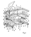
- the actuator is used to rotate a turning device 1 by 180 °.
- the turning device With the turning device, persons are brought from a back into a prone position and vice versa, without having to move the person himself.
- the turning device 1 is used in acute respiratory distress syndrome (ARDS) patients in whom an acute lung injury has occurred.
- ARDS acute respiratory distress syndrome
- the turning device can also be used in other severe lung diseases or for their prophylaxis.
- ARDS acute respiratory distress syndrome
- Such a turning device is the subject of the German patent application 10 2008 064 560 ,
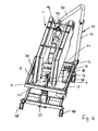
- the turning device 1 has a back part 2 and a belly part 3, which are pivotally connected to a U-shaped support 11.
- the back part 2 has a rectangular outline and is centrally provided on its one narrow side with a projection 4, on which the patient can lay his head.
- the belly part 3 is provided at the level of the projection 3 with a corresponding rectangular recess 5, so that the face part of the patient 6 is exposed.
- the back part 2 and the belly part 3 are articulated on a longitudinal side by lugs 7, 8 on two upwardly directed legs 9, 10 of the U-shaped support 11 ( Fig. 3 ).
- the legs 9, 10 are interconnected by a transverse web 12, which extends in the longitudinal direction of the back part 2 and the belly part 3, respectively.
- the upper flaps 7 are connected at their upper end fixed to the back part 2 and articulated at its lower end at the upper end of the legs 9, 10 of the carrier 11.
- the lower ends of the tabs 8 are fixedly connected to the belly part 3, while the upper ends of the tabs 8 at the upper end of the legs 9, 10 of the carrier 11 are articulated.
- the tabs 7, 8 are each arranged on the opposite sides of the legs 9, 10 and in each case about the same axis 13 with respect to the legs 9, 10 pivotally.
- the pivot axes 13 are aligned with each other and extend in the longitudinal direction of the turning device. 1
- the transverse web 12 of the carrier 11 is displaceable on two mutually parallel rod-shaped guides 14, 15 perpendicular to the pivot axes 13 in a support frame 16 ( Fig. 1 . 2 . 5 and 6 ).
- the support frame 16 has a rectangular outline.
- the guides 14, 15 extend between the inner sides of the longitudinal frame parts 17, 18, which extend in the longitudinal direction of the turning device 1.
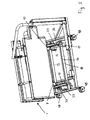
- the back part 2 and the belly part 3 of the turning device 1 are held together at the tabs 7, 8 opposite longitudinal side by two clamping devices 19, 20, so that the back part 2 and the belly part 3 when turning the turning device 1 can not be pivoted apart.
- the rigid tabs 7, 8 in conjunction with the legs 9, 10 of the carrier 11 provide for the firm connection between these parts 2, 3.
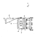
- the support frame 16 is mounted on lifting devices 21 to 23, which are fastened to a base frame 24.
- Two of the elevators 21, 22 are fixed to a narrow side of the rectangular base frame 24, while the lifting device 23 is fixed to the opposite narrow side of the base frame 24 in half width.
- the lifting device 23 is located between two narrow, upright struts 25, which connect the narrow side forming the frame part 26 with a parallel to him intermediate strut 27.
- the lifting device 23 is like the lifting devices 21, 22 supported on a support 28 which is suspended from the two struts 25.
- the two lifting devices 21, 22 are each supported on a support 29, 30, which are attached hanging on the two opposite, forming the longitudinal sides of the base frame frame members 31, 32.
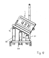
- the support frame 16 lies with its narrow sides forming frame members 33, 34 on the lifting devices 21 to 23. With the lifting devices 21 to 23, it is possible to rotate the support frame 16 together with the turning device 1 about its longitudinal axis and about an axis transverse thereto, as with reference to FIG Fig. 12 will be explained.
- the lifting devices 21 to 23 are each formed in a telescopic manner.
- the lifting devices are actuated pneumatically or hydraulically.
- An electric motor drive the lifting devices is possible.
- the lifting devices 21 to 23 can be adjusted continuously, so that the support frame 16 can be tilted continuously with the turning device 1 in any required position.
- each lifting device 21, 23 are two tabs 36, 37 from ( Fig. 3 ), which extend parallel to the frame parts 33, 34 of the support frame 16. Between the tabs 36, 37 engage tabs 38, 39 which project from the frame sides 33, 34 down and are pivotally connected by at least one axis 40 with the tabs 36, 37 of the lifting devices 21 to 23.
- the pivot axes 40 extend parallel to the longitudinal frame parts 17, 18 of the support frame sixteenth
- the tabs 36, 37 of the lifting devices 21 to 23 are upwardly projecting from a plate 41 which is mounted on the lifting devices 21 to 23 so as to be pivotable about a pivot axis 42 lying perpendicular to the pivot axis 40.
- the pivot axes 42 are parallel to the frame parts 33, 34 of the Support frame 16. Due to the two mutually perpendicular pivot axes 40, 42 of the support frame 16 is cardan connected to the lifting devices 21 to 23.
- a compensation unit 43 is provided on the frame part ( Fig. 1 and 2 ), which ensures that in such a tilting movement, the articulation points between the lifting devices 21, 22 and the frame member 34 are shortened or extended depending on the tilting direction.
- the compensation unit 43 has a half-length of the frame part 34 about a vertical axis pivotable tab 44, which is mounted at half its length about this vertical axis pivotally mounted on the frame part 34.
- a handlebar 45, 46 is articulated, the other ends of which are hingedly connected to the tabs 38, 39.
- These tabs 38, 39 are connected by a web 47 (FIG. Fig. 2 ), which rests against the underside of the frame part 34 and is pivotally connected to the handlebars 45, 46.
- the webs 47 with the advantageously integrally formed with them tabs 38, 39 are limitedly displaceable in the longitudinal direction of the frame member 34. Since the handlebars 45, 46 are hinged to the ends of the tab 44, the handlebars 45, 46 may overlap each other when the tab 44 is rotated accordingly about its vertical axis and exemplified in the Fig. 1 and 2 is shown. The adjustment of the compensation unit 43 takes place automatically when the support frame 16 is tilted.
- rollers 48 are provided which are mounted in each case about vertical axes 49 pivotally mounted on the base frame 24.
- the pivot axes 49 are received by bushes 50 which are fixed in the corner regions of the base frame 24.
- the rollers 48 are freely rotatable about their horizontal axes 51.
- the actuating device has at least one hoist 52, which is advantageously a pull rope.
- the hoist 52 is guided by a stator tube 53, which is L-shaped. With its vertical tube portion 54 it is attached to a vertical holder 55, preferably with at least one clamp 56.
- the holder 55 is fixed at its lower end to a support 57 which projects from the frame part 26 'of the base frame 24 and is secured thereto.
- the vertical pipe part 54 projects over the holder 55 in the vertical direction and merges into a horizontal pipe part 58, from which the hoist 52 is led out.
- a thrust member is slidably housed in the longitudinal direction of the tube to which the hoist 52 is connected.
- the thrust member is seated on a threaded spindle (not shown), which is guided by a tube 60 axially adjoining the tube 60 and is rotatable by means of a drive 61.
- the drive 61 sits on the frame part 31 of the base frame 24 (FIG. Fig. 1 ). With the help of the drive 61 and the threaded spindle of the thrust member can be moved in the pipe 59 and accordingly the hoist 52 can be retracted or released from the stator tube 53.
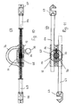
- a connection unit 62 is provided ( Fig. 1 . 8th and 9 ), which is designed so that it can be connected to the two parts 2, 3.
- the connecting unit 62 has two oppositely displaceable racks 63, 64 which extend parallel to each other and on both sides of a gear 65 extend, which engages in the two racks 63, 64. By Turning the gear 65, the two racks 63, 64 are moved in opposite directions to each other.
- connection unit 62 in suspension elements 68, 69 preferably suspension pins
- connection unit 62 in suspension elements 68, 69 preferably suspension pins
- Fig. 2 shows, these suspension elements 68, 69 in the area between the clamping devices 19, 20 laterally from the corresponding parts 2, 3 from.
- the suspension hooks 66, 67 can be easily pushed laterally onto the suspension elements 68, 69. With the help of the gear 65, the distance between the hooks 66, 67 can be easily adjusted to the distance between the suspension elements 68, 69.
- the gear 65 is non-rotatably mounted on a shaft 70 which protrudes from an adjusting wheel 71, which has a larger diameter than the gear 65 and can be rotated by hand to move the racks 63, 64 against each other.
- the rotatably connected to the setting wheel 71 shaft 70 is rotatably mounted in a housing 72.
- the setting wheel 71 rests on the housing 72 and is provided over its circumference with uniformly distributed plug-in openings 73. In it a plug pin 74 can be inserted, which is mounted in the housing 72 and projects beyond the dial 71 opposite housing side to the outside.
- the protruding end of the plug pin 74 is provided with a handle 75, preferably a ring, with which the plug pin 74 can be pulled down against spring force from the respective plug-in opening 73. As soon as the plug pin 74 releases the setting wheel 71, it can be rotated to change the distance between the hooks 66, 67. Subsequently, the locking pin 74 is inserted under spring force into the corresponding insertion opening 73, whereby the setting wheel 71 is secured against rotation.
- the two racks 63, 64 extend through the housing 72, in which they are guided in their longitudinal direction.
- a suspension eye 76 is fixed, in which the hoist 52 can be suspended with a corresponding suspension member 77 ( Fig. 1 and 2 ).
- the stator tube 53 is provided in the region of the connecting unit 62 opposite longitudinal side of the turning device 1 in the corresponding corner region of the base frame 24 in the manner described.
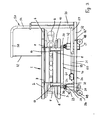
- the stator tube 53 is arranged such that the horizontal tube part 58, viewed in plan view of the actuating device, forms an acute angle with the corresponding longitudinal side 78 of the turning device 1. This angle is advantageously in the range between about 10 ° and 30 °.
- the horizontal tube part 58 is so long that its free end 79 is approximately at the level of the connection unit 62. If the hoist 52 is hung in the suspension eye 76, then the hoist 52 extends obliquely upward in the region above the turning device 1 to the tube part 58.
- the turning device 1 is attached to the upright tube 53 opposite longitudinal side 80 is raised, wherein the tabs 7, 8 of the turning device relative to the legs 9, 10 of the carrier 11 are pivoted.
- the carrier 6 on the guides 14, 15 of the in Fig. 1 shifted starting position from postponed.
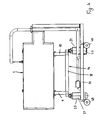
- Die 4 to 6 and 8th show the turning device in a central position in which the back part 2 and the belly part 3 are pivoted upwards by 90 °, so that they extend vertically.
- the carrier 11 has been moved on the guides 14, 15 approximately to half its length.
- the tube part 58 extends obliquely with respect to the longitudinal axis of the turning device 1, arises when pulling the hoist 52 in the stator tube 53 on the carrier 11 in the longitudinal direction of the guides 14, 15 directed force component, whereby the carrier 11 reliably along the guides 14, 15th is moved during the turning process.
- the stator tube 53 is designed and arranged such that the hoist 52 extends obliquely from the tube part 58 to the attachment eye 76 ( Fig. 6 and 8th ). This has the consequence that the hoist 52 still has to be retracted slightly.
- the turning device 1 is thereby further rotated from the vertical position, so that it reliably reaches the position turned by 180 °.
- the turning device 1 Since the carrier 11 is displaced during the turning process and the turning device is articulated to the carrier 11, the turning device 1 retains approximately its position relative to the support frame 16 at.
- the support frame 16 can be brought with the help of the lifting devices 21 to 23 in an inclined position by the lifting devices are extended to different heights.
- the turning device 1 can in this case be rotated about its longitudinal axis both to the right and to the left by the lifting devices are extended accordingly.
- the lifting devices 21 to 23 so that the turning device 1 can be tilted not only about its longitudinal axis but also about its transverse axis. In this case, the head or foot region of the patient 6 can be increased accordingly.
Landscapes
- Health & Medical Sciences (AREA)
- Nursing (AREA)
- Life Sciences & Earth Sciences (AREA)
- Animal Behavior & Ethology (AREA)
- General Health & Medical Sciences (AREA)
- Public Health (AREA)
- Veterinary Medicine (AREA)
- Accommodation For Nursing Or Treatment Tables (AREA)
Description
Die Erfindung betrifft eine Einrichtung mit einer zur Bewegung von lungenkranken Patienten vorgesehene Wendevorrichtung und einer Betätigungsvorrichtung nach dem Oberbegriff des Anspruches 1.The invention relates to a device with a device for the movement of pulmonary diseased patient turning device and an actuating device according to the preamble of
Es sind Wendevorrichtungen bekannt (
Der Erfindung liegt die Aufgabe zugrunde, die gattungsgemäße Einrichtung so auszubilden, dass die Wendevorrichtung in einfacher Weise um ihre Wendeachse gedreht werden kann.The invention has the object of providing the generic device in such a way that the turning device can be rotated in a simple manner about its turning axis.
Diese Aufgabe wird bei der gattungsgemäßen Einrichtung erfindungsgemäß mit den kennzeichnenden Merkmalen des Anspruches 1 gelöst.This object is achieved in the generic device according to the invention with the characterizing features of
Die erfindungsgemäße Einrichtung hat wenigstens einen Träger, an dem die Wendevorrichtung gehalten ist. Dieser Träger wird beim Wendevorgang quer zur Wendeachse der Wendevorrichtung verschoben. Dadurch wird erreicht, dass die Wendevorrichtung beim Wendevorgang ihre relative Lage innerhalb der Betätigungsvorrichtung beibehält. Der Schwerpunkt der Wendevorrichtung bleibt beim Wendevorgang infolge der Verschiebbarkeit des Trägers quer zur Wendeachse ungefähr gleich. Die Wendevorrichtung kann darum so an der Betätigungsvorrichtung vorgesehen sein, dass sich die Wendevorrichtung stets etwa im Schwerpunkt der Betätigungsvorrichtung während des Wendevorganges befindet. Dadurch ist ein sehr sicheres Wenden des Patienten gewährleistet.The device according to the invention has at least one support on which the turning device is held. This carrier is moved during the turning process transversely to the turning axis of the turning device. This ensures that the turning device maintains its relative position within the actuator during the turning process. The center of gravity of the turning device remains approximately the same during the turning process as a result of the displaceability of the carrier transversely to the turning axis. The turning device can therefore be provided on the actuating device that the turning device is always about the center of gravity of the actuator during the turning process. This ensures a very safe turning of the patient.
Vorteilhaft ist der Träger auf Führungen verschiebbar, die an einem Tragrahmen vorgesehen sind. Der Träger lässt sich dann beim Wendevorgang zuverlässig längs der Führungen verschieben, so dass der Wendevorgang durch die Verschiebbarkeit des Trägers nicht beeinträchtigt wird.Advantageously, the carrier is displaceable on guides which are provided on a support frame. The carrier can then move reliably during the turning process along the guides, so that the turning process is not affected by the displaceability of the wearer.
Um einen zuverlässigen Wendevorgang beim Verschieben des Trägers zu erreichen, ist die Wendevorrichtung vorteilhaft schwenkbar mit dem Träger verbunden.In order to achieve a reliable turning process when moving the carrier, the turning device is advantageously pivotally connected to the carrier.
Eine kompakte Ausbildung der Einrichtung ergibt sich, wenn der Träger U-förmig ausgebildet ist und die Wendevorrichtung mit Laschen an aufrecht stehende Schenkel des Trägers angelenkt ist. Der U-förmige Träger ist in diesem Falle in vorteilhafter Weise hochkant angeordnet, so dass er in Verschieberichtung nur wenig Bauraum beansprucht.A compact design of the device results when the carrier is U-shaped and the turning device is articulated with tabs on upright leg of the carrier. The U-shaped support is advantageously arranged edgewise in this case, so that it takes up little space in the direction of displacement.
Damit die Wendevorrichtung beim Wendevorgang einfach betätigt werden kann, ist die Betätigungsvorrichtung mit wenigstens einem Hebezeug versehen. Mit ihm lässt sich die Wendevorrichtung problemlos in der gewünschten Richtung wenden.Thus, the turning device can be easily operated during the turning process, the actuator is provided with at least one hoist. With it, the turning device can easily turn in the desired direction.
Das Hebezeug wird vorteilhaft an der den Laschen gegenüberliegenden Seite mit der Wendevorrichtung verbunden. Wird die Wendevorrichtung mit dem Hebezeug angehoben, dann kann sie an der gegenüberliegenden Seite relativ zum Träger schwenken. Je mehr die Wendevorrichtung durch das Hebezeug angehoben wird, umso stärker schwenkt die Wendevorrichtung relativ zum Träger, der gleichzeitig quer zur Wendeachse verschoben wird.The hoist is advantageously connected to the opposite side of the tabs with the turning device. If the turning device is lifted with the hoist, then it can pivot on the opposite side relative to the carrier. The more the turning device is lifted by the hoist, the more pivoting the turning device relative to the carrier, which is simultaneously moved transversely to the turning axis.
Es ist zweckmäßig, wenn an die Wendevorrichtung wenigstens eine Einhängeeinheit angeschlossen werden kann, die mit dem Hebezeug verbunden werden kann. Die Einhängeeinheit muss in diesem Falle nicht stets an der Wendevorrichtung vorhanden sein, sondern lässt sich erst dann anschließen, wenn ein Wendevorgang ausgeführt werden soll.It is useful if at least one suspension unit can be connected to the turning device, which is connected to the hoist can be. In this case, the suspension unit does not always have to be present at the turning device, but can only be connected when a turning process is to be carried out.
Die Einhängeeinheit ist zweckmäßig mit relativ zueinander verstellbaren Verstellteilen versehen, die mit Einhängeelementen versehen sind. Mit den relativ verstellbaren Verstellteilen lässt sich der Abstand zwischen den Einhängeelementen sehr einfach einstellen, so dass die Einhängeeinheit an unterschiedliche Wendevorrichtungen oder unterschiedliche Abstände angepasst werden kann. Mit den Einhängeelementen lässt sich die Einhängeeinheit einfach an der Wendevorrichtung befestigen.The suspension unit is expediently provided with adjustable adjusting parts which are provided with suspension elements. With the relatively adjustable adjustment parts, the distance between the suspension elements can be adjusted very easily, so that the suspension unit can be adapted to different turning devices or different distances. The suspension elements can be easily attached to the turning device with the suspension elements.
Das Hebezeug, das vorteilhaft ein Seil ist, verläuft durch ein Standrohr. Es hat einen oberen, abgewinkelten, vorteilhaft etwa horizontal verlaufenden Rohrteil, der sich unter einem spitzen Winkel zur Wendeachse erstreckt, in Draufsicht auf die Wendevorrichtung in ihrer Grundstellung gesehen. Aufgrund dieser Schräglage des oberen Rohrteiles wird beim Wendevorgang auf den Träger eine Kraftkomponente in Verschieberichtung ausgeübt. Dadurch lässt sich der Träger beim Wendevorgang einfach längs der Führungen verschieben.The hoist, which is advantageously a rope, passes through a standpipe. It has an upper, angled, advantageously extending approximately horizontally tubular part which extends at an acute angle to the turning axis, viewed in plan view of the turning device in its basic position. Due to this inclined position of the upper tube part, a force component in the displacement direction is exerted on the carrier during the turning process. As a result, the carrier can easily move along the guides during the turning process.
Damit die Wendevorrichtung nicht nur um ihre Wendeachse gedreht, sondern beispielsweise auch unterschiedlich geneigt werden kann, ist es vorteilhaft, den Tragrahmen der Wendevorrichtung auf Hubeinrichtungen zu lagern. Mit ihnen lässt sich die Wendevorrichtung um die Wendeachse oder um eine quer zu ihr liegende Achse problemlos in eine gewünschte Lage neigen.So that the turning device can not only be rotated about its turning axis, but also, for example, can be inclined differently, it is advantageous to mount the supporting frame of the turning device on lifting devices. With them, the turning device can be easily tilted about the turning axis or about an axis lying transversely to her axis in a desired position.
Weitere Merkmale der Erfindung ergeben sich aus den weiteren Ansprüchen, der Beschreibung und den Zeichnungen.Further features of the invention will become apparent from the other claims, the description and the drawings.
Die Erfindung wird anhand eines in der Zeichnung dargestellten Ausführungsbeispieles näher erläutert. Es zeigen
- Fig. 1
- in einer perspektivischen Unteransicht eine erfindungsgemäße Einrichtung,
- Fig. 2
- in einer anderen perspektivischen Darstellung schräg von unten die erfindungsgemäße Einrichtung,
- Fig. 3
- die erfindungsgemäße Einrichtung in Seitenansicht mit einer Wendevorrichtung, in der sich ein um 180° gedrehter Patient befindet,
- Fig. 4
- in einer Darstellung entsprechend
Fig. 3 die erfindungsgemäße Einrichtung mit der um 90° gewendeten Wendevorrichtung, - Fig. 5
- die Einrichtung in der Stellung gemäß
Fig. 4 in perspektivischer Darstellung, - Fig. 6
- die Einrichtung in der Stellung gemäß
Fig. 4 in einer anderen perspektivischen Darstellung, - Fig. 7
- in Stirnansicht die erfindungsgemäße Einrichtung mit der Wendevorrichtung in 180° gedrehter Lage,
- Fig. 8
- die erfindungsgemäße Einrichtung in Stirnansicht mit um 90° gewendeter Wendevorrichtung,
- Fig. 9
- die erfindungsgemäße Einrichtung von der anderen Stirnseite aus gesehen,
- Fig. 10
- in Seitenansicht eine Anschlusseinheit zum Einhängen eines Tragelementes der erfindungsgemäßen Einrichtung,
- Fig. 11
- die Anschlusseinheit gemäß
Fig. 10 in Draufsicht, - Fig. 12
- die Einrichtung in Stirnansicht mit geneigter Wendevorrichtung.
- Fig. 1
- in a perspective bottom view of an inventive device,
- Fig. 2
- in another perspective view obliquely from below the device according to the invention,
- Fig. 3
- the device according to the invention in side view with a turning device in which a patient rotated by 180 ° is located,
- Fig. 4
- in a representation accordingly
Fig. 3 the inventive device with the turned by 90 ° turning device, - Fig. 5
- the device in the position according to
Fig. 4 in perspective, - Fig. 6
- the device in the position according to
Fig. 4 in another perspective view, - Fig. 7
- in end view, the device according to the invention with the turning device in 180 ° rotated position,
- Fig. 8
- the inventive device in front view with turned by 90 ° turning device,
- Fig. 9
- the device according to the invention seen from the other end side,
- Fig. 10
- in side view, a connection unit for suspending a support element of the device according to the invention,
- Fig. 11
- the connection unit according to
Fig. 10 in plan view, - Fig. 12
- the device in front view with inclined turning device.
Die Betätigungsvorrichtung dient dazu, eine Wendevorrichtung 1 um 180° zu drehen. Mit der Wendevorrichtung werden Personen aus einer Rückenin eine Bauchlage und umgekehrt gebracht, ohne dass die Person dabei selbst bewegt werden muss. Die Wendevorrichtung 1 wird bei ARDS-Patienten (Acute Respiratory Distress Syndrome) eingesetzt, bei denen ein akutes Lungenversagen aufgetreten ist. Darüber hinaus kann die Wendevorrichtung auch bei anderen schweren Lungenerkrankungen oder auch zu deren Prophylaxe eingesetzt werden. Eine solche Wendevorrichtung ist Gegenstand der deutschen Patentanmeldung
Die Wendevorrichtung 1 hat ein Rückenteil 2 und ein Bauchteil 3, die schwenkbar mit einem U-förmigen Träger 11 verbunden sind. Das Rückenteil 2 hat rechteckförmigen Umriss und ist an seiner einen Schmalseite mittig mit einem Vorsprung 4 versehen, auf den der Patient seinen Kopf legen kann.The
Das Bauchteil 3 ist in Höhe des Vorsprunges 3 mit einer entsprechenden rechteckigen Aussparung 5 versehen, damit die Gesichtspartie des Patienten 6 frei liegt. Das Rückenteil 2 und das Bauchteil 3 sind an einer Längsseite durch Laschen 7, 8 an zwei aufwärts gerichtete Schenkel 9, 10 des U-förmigen Trägers 11 angelenkt (
Die oberen Laschen 7 sind mit ihrem oberen Ende fest mit dem Rückenteil 2 verbunden und mit ihrem unteren Ende am oberen Ende der Schenkel 9, 10 des Trägers 11 angelenkt. Die unteren Enden der Laschen 8 sind fest mit dem Bauchteil 3 verbunden, während die oberen Enden der Laschen 8 am oberen Ende der Schenkel 9, 10 des Trägers 11 angelenkt sind. Die Laschen 7, 8 sind jeweils auf den einander gegenüberliegenden Seiten der Schenkel 9, 10 angeordnet und jeweils um die gleiche Achse 13 gegenüber dem Schenkel 9, 10 schwenkbar. Die Schwenkachsen 13 liegen fluchtend zueinander und erstrecken sich in Längsrichtung der Wendevorrichtung 1.The
Der Quersteg 12 des Trägers 11 ist auf zwei parallel zueinander liegenden stangenförmigen Führungen 14, 15 senkrecht zu den Schwenkachsen 13 in einem Tragrahmen 16 verschiebbar (
Das Rückenteil 2 und das Bauchteil 3 der Wendevorrichtung 1 sind an der den Laschen 7, 8 gegenüberliegenden Längsseite durch zwei Spanneinrichtungen 19, 20 zusammengehalten, so dass das Rückenteil 2 und das Bauchteil 3 beim Wenden der Wendevorrichtung 1 nicht auseinandergeschwenkt werden können. An der gegenüberliegenden Seite sorgen die starren Laschen 7, 8 in Verbindung mit den Schenkeln 9, 10 des Trägers 11 für die feste Verbindung zwischen diesen Teilen 2, 3.The
Der Tragrahmen 16 ist auf Hubeinrichtungen 21 bis 23 gelagert, die an einem Grundrahmen 24 befestigt sind. Zwei der Hubeinrichtungen 21, 22 sind an einer Schmalseite des rechteckigen Grundrahmens 24 befestigt, während die Hubeinrichtung 23 an der gegenüberliegenden Schmalseite des Grundrahmens 24 in halber Breite befestigt ist. Die Hubeinrichtung 23 liegt zwischen zwei schmalen, hochkant stehenden Streben 25, welche den die Schmalseite bildenden Rahmenteil 26 mit einer parallel zu ihm verlaufenden Zwischenstrebe 27 verbinden. Die Hubeinrichtung 23 ist wie die Hubeinrichtungen 21, 22 auf einer Stütze 28 abgestützt, die hängend an den beiden Streben 25 gehalten ist.The
Die beiden Hubeinrichtungen 21, 22 sind jeweils auf einer Stütze 29, 30 abgestützt, die hängend an den beiden einander gegenüberliegenden, die Längsseiten des Grundrahmens bildenden Rahmenteilen 31, 32 befestigt sind.The two
Der Tragrahmen 16 liegt mit seinen die Schmalseiten bildenden Rahmenteilen 33, 34 auf den Hubeinrichtungen 21 bis 23 auf. Mit den Hubeinrichtungen 21 bis 23 ist es möglich, den Tragrahmen 16 zusammen mit der Wendevorrichtung 1 um seine Längsachse sowie um eine dazu quer liegende Achse zu drehen, wie anhand von
Die Hubeinrichtungen 21 bis 23 sind jeweils teleskopförmig ausgebildet. Vorteilhaft werden die Hubeinrichtungen pneumatisch oder hydraulisch betätigt. Auch ein elektromotorischer Antrieb der Hubeinrichtungen ist möglich. Die Hubeinrichtungen 21 bis 23 können stufenlos verstellt werden, so dass der Tragrahmen 16 mit der Wendevorrichtung 1 in jede erforderliche Lage stufenlos gekippt werden kann.The
Von jeder Hubeinrichtung 21, 23 stehen zwei Laschen 36, 37 ab (
Die Laschen 36, 37 der Hubeinrichtungen 21 bis 23 stehen von einer Platte 41 aufwärts ab, die um eine senkrecht zur Schwenkachse 40 liegende Schwenkachse 42 schwenkbar auf den Hubeinrichtungen 21 bis 23 gelagert ist. Die Schwenkachsen 42 liegen parallel zu den Rahmenteilen 33, 34 des Tragrahmens 16. Aufgrund der beiden rechtwinklig zueinander liegenden Schwenkachsen 40, 42 ist der Tragrahmen 16 kardangelenkartig mit den Hubeinrichtungen 21 bis 23 verbunden.The
Wird der Tragrahmen 16, wie beispielhaft in
An den Ecken des Grundrahmens 24 sind Laufrollen 48 vorgesehen, die jeweils um vertikale Achsen 49 schwenkbar am Grundrahmen 24 gelagert sind. Die Schwenkachsen 49 werden von Buchsen 50 aufgenommen, die in den Eckbereichen des Grundrahmens 24 befestigt sind. Die Laufrollen 48 sind um ihre horizontalen Achsen 51 frei drehbar.At the corners of the
Um die Wendevorrichtung 1 um ihre Längsachse zu wenden, hat die Betätigungsvorrichtung wenigstens ein Hebezeug 52, das vorteilhaft ein Zugseil ist. Das Hebezeug 52 wird durch ein Ständerrohr 53 geführt, das L-förmig ausgebildet ist. Mit seinem vertikalen Rohrteil 54 ist es an einem vertikalen Halter 55 befestigt, vorzugsweise mit wenigstens einer Klemmschelle 56. Der Halter 55 ist mit seinem unteren Ende an einem Träger 57 befestigt, der vom Rahmenteil 26' des Grundrahmens 24 absteht und an ihm befestigt ist. Der vertikale Rohrteil 54 steht über den Halter 55 in Vertikalrichtung über und geht in einen horizontalen Rohrteil 58 über, aus dem das Hebezeug 52 herausgeführt ist.To turn the
An das untere Ende des Rohrteiles 54 schließt rechtwinklig ein Rohr 59 an (
In den
An den voneinander abgewandten Enden sind die Zahnstangen 63, 64 jeweils mit einem Einhängehaken 66, 67 versehen, mit denen die Anschlusseinheit 62 in Einhängeelemente 68, 69, vorzugsweise Einhängestifte, eingehängt werden können, die am Rückenteil 2 sowie am Bauchteil 3 vorgesehen sind. Wie
Das Zahnrad 65 sitzt drehfest auf einer Welle 70, die von einem Stellrad 71 absteht, das größeren Durchmesser als das Zahnrad 65 hat und von Hand gedreht werden kann, um die Zahnstangen 63, 64 gegeneinander zu verschieben. Die drehfest mit dem Stellrad 71 verbundene Welle 70 ist in einem Gehäuse 72 drehbar gelagert. Das Stellrad 71 liegt auf dem Gehäuse 72 auf und ist über seinen Umfang mit gleichmäßig verteilt angeordneten Stecköffnungen 73 versehen. In sie kann ein Steckbolzen 74 gesteckt werden, der im Gehäuse 72 gelagert und über die dem Stellrad 71 gegenüberliegende Gehäuseseite nach außen ragt. Das überstehende Ende des Steckbolzens 74 ist mit einer Handhabe 75, vorzugsweise einem Ring, versehen, mit dem sich der Steckbolzen 74 gegen Federkraft nach unten aus der jeweiligen Stecköffnung 73 herausziehen lässt. Sobald der Steckbolzen 74 das Stellrad 71 freigibt, kann es zur Veränderung des Abstandes zwischen den Einhängehaken 66, 67 gedreht werden. Anschließend wird der Steckbolzen 74 unter Federkraft in die entsprechende Stecköffnung 73 gesteckt, wodurch das Stellrad 71 gegen Verdrehen gesichert ist.The
Die beiden Zahnstangen 63, 64 erstrecken sich durch das Gehäuse 72, in dem sie in ihrer Längsrichtung geführt sind.The two
Auf der das Stellrad 71 aufweisenden Gehäuseseite ist eine Einhängeöse 76 befestigt, in die das Hebezeug 52 mit einem entsprechenden Einhängeglied 77 eingehängt werden kann (
Das Ständerrohr 53 ist im Bereich des der Anschlusseinheit 62 gegenüberliegenden Längsseite der Wendevorrichtung 1 im entsprechenden Eckbereich des Grundrahmens 24 in der beschriebenen Weise vorgesehen. Das Ständerrohr 53 ist so angeordnet, dass der horizontale Rohrteil 58, in Draufsicht auf die Betätigungsvorrichtung gesehen, einen spitzen Winkel mit der entsprechenden Längsseite 78 der Wendevorrichtung 1 einschließt. Dieser Winkel liegt vorteilhaft im Bereich zwischen etwa 10° und 30°. Außerdem ist der horizontale Rohrteil 58 so lang, dass sein freies Ende 79 etwa in Höhe der Anschlusseinheit 62 liegt. Wird das Hebezeug 52 in die Einhängeöse 76 eingehängt, dann verläuft das Hebezeug 52 im Bereich oberhalb der Wendevorrichtung 1 schräg aufwärts zum Rohrteil 58. Wird das Hebezeug 52 mit dem Antrieb 61 in das Rohr 58 gezogen, dann wird die Wendevorrichtung 1 an der dem Ständerrohr 53 gegenüberliegenden Längsseite 80 angehoben, wobei die Laschen 7, 8 der Wendevorrichtung gegenüber den Schenkeln 9, 10 des Trägers 11 verschwenkt werden. Mit zunehmendem Schwenkweg der Wendevorrichtung 1 wird der Träger 6 auf den Führungen 14, 15 von der in
In dieser aufrechten Lage der Wendevorrichtung 1 ist das Hebezeug 52 am weitesten in das Ständerrohr 53 eingezogen worden.In this upright position of the
Da der Rohrteil 58 schräg in Bezug auf die Längsachse der Wendevorrichtung 1 verläuft, entsteht beim Einziehen des Hebezeuges 52 in das Ständerrohr 53 am Träger 11 eine in Längsrichtung der Führungen 14, 15 gerichtete Kraftkomponente, wodurch der Träger 11 zuverlässig längs der Führungen 14, 15 beim Wendevorgang verschoben wird.Since the
Sobald die vertikale Lage der Wendevorrichtung 1 erreicht ist, wird mittels des Antriebes 61 das Hebezeug 52 wieder aus dem Ständerrohr 53 abgelassen. Dadurch wird die Wendevorrichtung 1 weitergeschwenkt und dabei der Träger 11 auf den Führungen 14, 15 weiter verschoben, bis die Wendevorrichtung 1 die in
Damit die Wendevorrichtung aus der vertikalen Lage weiter gewendet wird, ist das Ständerrohr 53 so ausgebildet und angeordnet, dass sich das Hebezeug 52 vom Rohrteil 58 aus schräg bis zur Einhängeöse 76 erstreckt (
Da der Träger 11 beim Wendevorgang verschoben wird und die Wendevorrichtung an den Träger 11 angelenkt ist, behält die Wendevorrichtung 1 etwa ihre Lage relativ zum Tragrahmen 16 bei.Since the
Um die Wendevorrichtung 1 wieder zurück in die Ausgangslage gemäß
Der Tragrahmen 16 lässt sich mit Hilfe der Hubeinrichtungen 21 bis 23 auch in eine Schräglage bringen, indem die Hubeinrichtungen unterschiedlich weit ausgefahren werden. Die Wendevorrichtung 1 kann hierbei um ihre Längsachse sowohl nach rechts als auch nach links gedreht werden, indem die Hubeinrichtungen entsprechend ausgefahren werden.The
Es ist auch möglich, die Hubeinrichtungen 21 bis 23 so auszufahren, dass die Wendevorrichtung 1 nicht nur um ihre Längsachse, sondern auch um ihre Querachse gekippt werden kann. In diesem Falle kann der Kopf- oder der Fußbereich des Patienten 6 entsprechend erhöht werden.It is also possible to extend the
Claims (9)
- Apparatus with a turning device (1) for the movement of patients with pulmonary diseases and an actuation device for the turning device (1), which is rotatable around a turning axis,
characterised in that the turning device (1) comprises a back part (2) and a belly part (3), which are connected rotatably about 180° with at least one beam (11) of the actuation device, slidable transversely to the turning axis of the turning device (1) in such a way that the center of gravity of the turning device (1) is always positioned approximately within the center of gravity of the actuation device during the turning operation. - Apparatus according to claim 1,
characterised in that the beam (11) is movable on guides (14, 15), provided on a supporting frame (16). - Apparatus according to one of the claims 1 or 2,
characterised in that the beam (11) is designed in an U-shaped form and that the turning device (1) is linked by lugs (7, 8) to upright standing legs (9, 10) of the beam (11). - Apparatus according to one of the claims 1 to 3,
characterised in that the actuating device comprises at least one hoist (52), by means of which the turning device (1) is liftable during the turning operation. - Apparatus according to claim 4,
characterised in that the hoist (52) is connectable at the side (80) opposite to the lugs (7, 8) of the turning device (1). - Apparatus according to one of the claims 1 to 5,
characterised in that to the turning device (1), at least one hang-up unit (62) is connectable to which the hoist (52) is connectable. - Apparatus according to claim 6,
characterised in that the hang-up unit (62) comprises two adjustment components (63, 64), adjustable relatively to one another, provided with hang-up elements (66, 67). - Apparatus according to one of the claims 4 to 7,
characterised in that the hoist (52) passes through an upright standpipe (53), comprising an upper, approximately horizontal tube part (58), extending at a sharp angle to the turning axis when viewed from the top of the turning device (1). - Apparatus according to one of the claims 1 to 8,
characterised in that the supporting frame (16) is mounted on lifting devices (21 to 23), by means of which the supporting frame (16) can be inclined.
Applications Claiming Priority (1)
| Application Number | Priority Date | Filing Date | Title |
|---|---|---|---|
| DE201010032719 DE102010032719A1 (en) | 2010-07-23 | 2010-07-23 | Actuating device for a turning device intended for the movement of patients with diseased lungs |
Publications (3)
| Publication Number | Publication Date |
|---|---|
| EP2409675A2 EP2409675A2 (en) | 2012-01-25 |
| EP2409675A3 EP2409675A3 (en) | 2012-09-12 |
| EP2409675B1 true EP2409675B1 (en) | 2014-02-26 |
Family
ID=44658519
Family Applications (1)
| Application Number | Title | Priority Date | Filing Date |
|---|---|---|---|
| EP20110005283 Not-in-force EP2409675B1 (en) | 2010-07-23 | 2011-06-29 | Actuation device for a turning device for the movement of patients with pulmonary diseases |
Country Status (2)
| Country | Link |
|---|---|
| EP (1) | EP2409675B1 (en) |
| DE (1) | DE102010032719A1 (en) |
Family Cites Families (8)
| Publication number | Priority date | Publication date | Assignee | Title |
|---|---|---|---|---|
| US5479665A (en) * | 1983-09-09 | 1996-01-02 | Cassidy; Joseph P. | Automated tri-fold bed |
| US5539941A (en) * | 1993-04-13 | 1996-07-30 | Fuller; Carmel U. | Bed patient health care system |
| DE10001687A1 (en) * | 2000-01-11 | 2001-07-12 | Albrecht Hoerlin | Bed for treatment of bedsores, with bed frame mounted on at least three hydraulic cylinders which can be pressurized |
| US6668396B2 (en) * | 2001-12-28 | 2003-12-30 | Ching-Hua Wei | Turning mechanism for a patient confined to a bed |
| US7886379B2 (en) * | 2007-10-14 | 2011-02-15 | Bedlab, Llc | Support surface that modulates to cradle a patient's midsection |
| DE102008064560A1 (en) | 2008-12-29 | 2010-07-01 | Aacurat Gmbh | Turning device for use in hospital for movement of acute respiratory distress syndrome patient, has rear part with support for patient, where rear part is coupled with lower side part such that device is rotatable around given degrees |
| DE202009000351U1 (en) * | 2009-01-13 | 2009-03-19 | Mühle, Werner | rearrangement bed |
| DE102009006929B3 (en) * | 2009-02-02 | 2010-06-02 | Klafs Gmbh & Co. Kg | Oscillating bed i.e. solarium bed, has guide enabling oscillating movement of couch around virtual oscillating axis running in longitudinal direction of couch, where guide is formed by two ramps exhibiting angle to each other |
-
2010
- 2010-07-23 DE DE201010032719 patent/DE102010032719A1/en not_active Withdrawn
-
2011
- 2011-06-29 EP EP20110005283 patent/EP2409675B1/en not_active Not-in-force
Also Published As
| Publication number | Publication date |
|---|---|
| EP2409675A3 (en) | 2012-09-12 |
| DE102010032719A1 (en) | 2012-01-26 |
| EP2409675A2 (en) | 2012-01-25 |
Similar Documents
| Publication | Publication Date | Title |
|---|---|---|
| DE2232278C3 (en) | Single column drawing table | |
| DE3628782C2 (en) | ||
| DE2548261A1 (en) | SAFETY DEVICE FOR ACCESS TO THE UPPER LEVEL OF CARRIAGES OF DIFFERENT HEIGHT | |
| DE2459444C3 (en) | Assembly trolley for parts of a prefabricated wall system | |
| DE60110416T2 (en) | Motorcycle Service Stand | |
| DE29704769U1 (en) | Bath lift for seniors and the disabled | |
| DE2165244C2 (en) | Device for lifting and tipping motor vehicles | |
| EP0861952B1 (en) | Scaffold with vertically movable outtrigger | |
| EP3500137B1 (en) | Item of seating furniture | |
| EP2409675B1 (en) | Actuation device for a turning device for the movement of patients with pulmonary diseases | |
| DE2007570C3 (en) | Device for lifting and lowering disabled people in bathtubs | |
| EP0853936B1 (en) | Bath lift for elderly and disabled persons | |
| DE102005014637B3 (en) | Pivotable leg support for wheel chairs to facilitate getting in or out from the side has calf plate pivotable from support to rest postion using snap-in hinge | |
| DE102006051289B4 (en) | seating | |
| DE3933237A1 (en) | Table with height- and angle-adjustable plate | |
| EP1921221B1 (en) | Height-adjustable ladder scaffold | |
| EP2856915B1 (en) | Folding mechanism with parallelogramm-type lifting arrangement for a folding bed | |
| DE102014108755A1 (en) | Patientenaufstehhilfe | |
| DE2419339A1 (en) | Height-adjustable, mobile scaffolding | |
| DE2049282B2 (en) | Adjustable height patient chair - has shin support swung into triangular space formed by lifting mechanism on lowering | |
| EP3806802B1 (en) | Transport system | |
| DE3412755A1 (en) | Extendable running gear for a standing body | |
| DE2435477B1 (en) | Attachment device with support of the upper link against the lower link by leaf springs, especially for a tractor | |
| EP2091495B1 (en) | Bath tub lifter | |
| DE60114021T2 (en) | DEVICE FOR ORIENTING A VEHICLE BY PULLING |
Legal Events
| Date | Code | Title | Description |
|---|---|---|---|
| AK | Designated contracting states |
Kind code of ref document: A2 Designated state(s): AL AT BE BG CH CY CZ DE DK EE ES FI FR GB GR HR HU IE IS IT LI LT LU LV MC MK MT NL NO PL PT RO RS SE SI SK SM TR |
|
| AX | Request for extension of the european patent |
Extension state: BA ME |
|
| PUAI | Public reference made under article 153(3) epc to a published international application that has entered the european phase |
Free format text: ORIGINAL CODE: 0009012 |
|
| PUAL | Search report despatched |
Free format text: ORIGINAL CODE: 0009013 |
|
| AK | Designated contracting states |
Kind code of ref document: A3 Designated state(s): AL AT BE BG CH CY CZ DE DK EE ES FI FR GB GR HR HU IE IS IT LI LT LU LV MC MK MT NL NO PL PT RO RS SE SI SK SM TR |
|
| AX | Request for extension of the european patent |
Extension state: BA ME |
|
| RIC1 | Information provided on ipc code assigned before grant |
Ipc: A61G 7/008 20060101AFI20120803BHEP Ipc: A61G 7/10 20060101ALI20120803BHEP |
|
| 17P | Request for examination filed |
Effective date: 20130312 |
|
| RIC1 | Information provided on ipc code assigned before grant |
Ipc: A61G 7/008 20060101AFI20130617BHEP Ipc: A61G 7/10 20060101ALI20130617BHEP |
|
| GRAP | Despatch of communication of intention to grant a patent |
Free format text: ORIGINAL CODE: EPIDOSNIGR1 |
|
| INTG | Intention to grant announced |
Effective date: 20130902 |
|
| GRAS | Grant fee paid |
Free format text: ORIGINAL CODE: EPIDOSNIGR3 |
|
| GRAA | (expected) grant |
Free format text: ORIGINAL CODE: 0009210 |
|
| AK | Designated contracting states |
Kind code of ref document: B1 Designated state(s): AL AT BE BG CH CY CZ DE DK EE ES FI FR GB GR HR HU IE IS IT LI LT LU LV MC MK MT NL NO PL PT RO RS SE SI SK SM TR |
|
| REG | Reference to a national code |
Ref country code: GB Ref legal event code: FG4D Free format text: NOT ENGLISH |
|
| REG | Reference to a national code |
Ref country code: CH Ref legal event code: EP |
|
| REG | Reference to a national code |
Ref country code: AT Ref legal event code: REF Ref document number: 653120 Country of ref document: AT Kind code of ref document: T Effective date: 20140315 |
|
| REG | Reference to a national code |
Ref country code: IE Ref legal event code: FG4D Free format text: LANGUAGE OF EP DOCUMENT: GERMAN |
|
| REG | Reference to a national code |
Ref country code: DE Ref legal event code: R096 Ref document number: 502011002184 Country of ref document: DE Effective date: 20140417 |
|
| REG | Reference to a national code |
Ref country code: NL Ref legal event code: VDEP Effective date: 20140226 |
|
| REG | Reference to a national code |
Ref country code: LT Ref legal event code: MG4D |
|
| PG25 | Lapsed in a contracting state [announced via postgrant information from national office to epo] |
Ref country code: NO Free format text: LAPSE BECAUSE OF FAILURE TO SUBMIT A TRANSLATION OF THE DESCRIPTION OR TO PAY THE FEE WITHIN THE PRESCRIBED TIME-LIMIT Effective date: 20140526 Ref country code: LT Free format text: LAPSE BECAUSE OF FAILURE TO SUBMIT A TRANSLATION OF THE DESCRIPTION OR TO PAY THE FEE WITHIN THE PRESCRIBED TIME-LIMIT Effective date: 20140226 Ref country code: IS Free format text: LAPSE BECAUSE OF FAILURE TO SUBMIT A TRANSLATION OF THE DESCRIPTION OR TO PAY THE FEE WITHIN THE PRESCRIBED TIME-LIMIT Effective date: 20140626 |
|
| PG25 | Lapsed in a contracting state [announced via postgrant information from national office to epo] |
Ref country code: NL Free format text: LAPSE BECAUSE OF FAILURE TO SUBMIT A TRANSLATION OF THE DESCRIPTION OR TO PAY THE FEE WITHIN THE PRESCRIBED TIME-LIMIT Effective date: 20140226 Ref country code: CY Free format text: LAPSE BECAUSE OF FAILURE TO SUBMIT A TRANSLATION OF THE DESCRIPTION OR TO PAY THE FEE WITHIN THE PRESCRIBED TIME-LIMIT Effective date: 20140226 Ref country code: SE Free format text: LAPSE BECAUSE OF FAILURE TO SUBMIT A TRANSLATION OF THE DESCRIPTION OR TO PAY THE FEE WITHIN THE PRESCRIBED TIME-LIMIT Effective date: 20140226 Ref country code: FI Free format text: LAPSE BECAUSE OF FAILURE TO SUBMIT A TRANSLATION OF THE DESCRIPTION OR TO PAY THE FEE WITHIN THE PRESCRIBED TIME-LIMIT Effective date: 20140226 Ref country code: PT Free format text: LAPSE BECAUSE OF FAILURE TO SUBMIT A TRANSLATION OF THE DESCRIPTION OR TO PAY THE FEE WITHIN THE PRESCRIBED TIME-LIMIT Effective date: 20140626 |
|
| PG25 | Lapsed in a contracting state [announced via postgrant information from national office to epo] |
Ref country code: LV Free format text: LAPSE BECAUSE OF FAILURE TO SUBMIT A TRANSLATION OF THE DESCRIPTION OR TO PAY THE FEE WITHIN THE PRESCRIBED TIME-LIMIT Effective date: 20140226 Ref country code: HR Free format text: LAPSE BECAUSE OF FAILURE TO SUBMIT A TRANSLATION OF THE DESCRIPTION OR TO PAY THE FEE WITHIN THE PRESCRIBED TIME-LIMIT Effective date: 20140226 |
|
| PG25 | Lapsed in a contracting state [announced via postgrant information from national office to epo] |
Ref country code: RO Free format text: LAPSE BECAUSE OF FAILURE TO SUBMIT A TRANSLATION OF THE DESCRIPTION OR TO PAY THE FEE WITHIN THE PRESCRIBED TIME-LIMIT Effective date: 20140226 Ref country code: EE Free format text: LAPSE BECAUSE OF FAILURE TO SUBMIT A TRANSLATION OF THE DESCRIPTION OR TO PAY THE FEE WITHIN THE PRESCRIBED TIME-LIMIT Effective date: 20140226 Ref country code: DK Free format text: LAPSE BECAUSE OF FAILURE TO SUBMIT A TRANSLATION OF THE DESCRIPTION OR TO PAY THE FEE WITHIN THE PRESCRIBED TIME-LIMIT Effective date: 20140226 Ref country code: CZ Free format text: LAPSE BECAUSE OF FAILURE TO SUBMIT A TRANSLATION OF THE DESCRIPTION OR TO PAY THE FEE WITHIN THE PRESCRIBED TIME-LIMIT Effective date: 20140226 |
|
| REG | Reference to a national code |
Ref country code: DE Ref legal event code: R097 Ref document number: 502011002184 Country of ref document: DE |
|
| PG25 | Lapsed in a contracting state [announced via postgrant information from national office to epo] |
Ref country code: PL Free format text: LAPSE BECAUSE OF FAILURE TO SUBMIT A TRANSLATION OF THE DESCRIPTION OR TO PAY THE FEE WITHIN THE PRESCRIBED TIME-LIMIT Effective date: 20140226 Ref country code: SK Free format text: LAPSE BECAUSE OF FAILURE TO SUBMIT A TRANSLATION OF THE DESCRIPTION OR TO PAY THE FEE WITHIN THE PRESCRIBED TIME-LIMIT Effective date: 20140226 Ref country code: ES Free format text: LAPSE BECAUSE OF FAILURE TO SUBMIT A TRANSLATION OF THE DESCRIPTION OR TO PAY THE FEE WITHIN THE PRESCRIBED TIME-LIMIT Effective date: 20140226 |
|
| PLBE | No opposition filed within time limit |
Free format text: ORIGINAL CODE: 0009261 |
|
| STAA | Information on the status of an ep patent application or granted ep patent |
Free format text: STATUS: NO OPPOSITION FILED WITHIN TIME LIMIT |
|
| PG25 | Lapsed in a contracting state [announced via postgrant information from national office to epo] |
Ref country code: LU Free format text: LAPSE BECAUSE OF FAILURE TO SUBMIT A TRANSLATION OF THE DESCRIPTION OR TO PAY THE FEE WITHIN THE PRESCRIBED TIME-LIMIT Effective date: 20140629 Ref country code: MC Free format text: LAPSE BECAUSE OF FAILURE TO SUBMIT A TRANSLATION OF THE DESCRIPTION OR TO PAY THE FEE WITHIN THE PRESCRIBED TIME-LIMIT Effective date: 20140226 |
|
| REG | Reference to a national code |
Ref country code: CH Ref legal event code: PL |
|
| 26N | No opposition filed |
Effective date: 20141127 |
|
| REG | Reference to a national code |
Ref country code: DE Ref legal event code: R097 Ref document number: 502011002184 Country of ref document: DE Effective date: 20141127 |
|
| REG | Reference to a national code |
Ref country code: IE Ref legal event code: MM4A |
|
| PG25 | Lapsed in a contracting state [announced via postgrant information from national office to epo] |
Ref country code: CH Free format text: LAPSE BECAUSE OF NON-PAYMENT OF DUE FEES Effective date: 20140630 Ref country code: LI Free format text: LAPSE BECAUSE OF NON-PAYMENT OF DUE FEES Effective date: 20140630 Ref country code: IE Free format text: LAPSE BECAUSE OF NON-PAYMENT OF DUE FEES Effective date: 20140629 |
|
| REG | Reference to a national code |
Ref country code: FR Ref legal event code: PLFP Year of fee payment: 5 |
|
| PG25 | Lapsed in a contracting state [announced via postgrant information from national office to epo] |
Ref country code: SI Free format text: LAPSE BECAUSE OF FAILURE TO SUBMIT A TRANSLATION OF THE DESCRIPTION OR TO PAY THE FEE WITHIN THE PRESCRIBED TIME-LIMIT Effective date: 20140226 |
|
| PGFP | Annual fee paid to national office [announced via postgrant information from national office to epo] |
Ref country code: GB Payment date: 20150624 Year of fee payment: 5 |
|
| PGFP | Annual fee paid to national office [announced via postgrant information from national office to epo] |
Ref country code: IT Payment date: 20150522 Year of fee payment: 5 Ref country code: FR Payment date: 20150527 Year of fee payment: 5 |
|
| PG25 | Lapsed in a contracting state [announced via postgrant information from national office to epo] |
Ref country code: MT Free format text: LAPSE BECAUSE OF FAILURE TO SUBMIT A TRANSLATION OF THE DESCRIPTION OR TO PAY THE FEE WITHIN THE PRESCRIBED TIME-LIMIT Effective date: 20140226 |
|
| PG25 | Lapsed in a contracting state [announced via postgrant information from national office to epo] |
Ref country code: SM Free format text: LAPSE BECAUSE OF FAILURE TO SUBMIT A TRANSLATION OF THE DESCRIPTION OR TO PAY THE FEE WITHIN THE PRESCRIBED TIME-LIMIT Effective date: 20140226 |
|
| PG25 | Lapsed in a contracting state [announced via postgrant information from national office to epo] |
Ref country code: GR Free format text: LAPSE BECAUSE OF FAILURE TO SUBMIT A TRANSLATION OF THE DESCRIPTION OR TO PAY THE FEE WITHIN THE PRESCRIBED TIME-LIMIT Effective date: 20140527 Ref country code: RS Free format text: LAPSE BECAUSE OF NON-PAYMENT OF DUE FEES Effective date: 20140226 Ref country code: BG Free format text: LAPSE BECAUSE OF FAILURE TO SUBMIT A TRANSLATION OF THE DESCRIPTION OR TO PAY THE FEE WITHIN THE PRESCRIBED TIME-LIMIT Effective date: 20140226 |
|
| PG25 | Lapsed in a contracting state [announced via postgrant information from national office to epo] |
Ref country code: TR Free format text: LAPSE BECAUSE OF FAILURE TO SUBMIT A TRANSLATION OF THE DESCRIPTION OR TO PAY THE FEE WITHIN THE PRESCRIBED TIME-LIMIT Effective date: 20140226 Ref country code: BE Free format text: LAPSE BECAUSE OF FAILURE TO SUBMIT A TRANSLATION OF THE DESCRIPTION OR TO PAY THE FEE WITHIN THE PRESCRIBED TIME-LIMIT Effective date: 20140630 Ref country code: HU Free format text: LAPSE BECAUSE OF FAILURE TO SUBMIT A TRANSLATION OF THE DESCRIPTION OR TO PAY THE FEE WITHIN THE PRESCRIBED TIME-LIMIT; INVALID AB INITIO Effective date: 20110629 |
|
| GBPC | Gb: european patent ceased through non-payment of renewal fee |
Effective date: 20160629 |
|
| REG | Reference to a national code |
Ref country code: FR Ref legal event code: ST Effective date: 20170228 |
|
| PG25 | Lapsed in a contracting state [announced via postgrant information from national office to epo] |
Ref country code: FR Free format text: LAPSE BECAUSE OF NON-PAYMENT OF DUE FEES Effective date: 20160630 |
|
| PG25 | Lapsed in a contracting state [announced via postgrant information from national office to epo] |
Ref country code: GB Free format text: LAPSE BECAUSE OF NON-PAYMENT OF DUE FEES Effective date: 20160629 |
|
| PG25 | Lapsed in a contracting state [announced via postgrant information from national office to epo] |
Ref country code: IT Free format text: LAPSE BECAUSE OF NON-PAYMENT OF DUE FEES Effective date: 20160629 |
|
| REG | Reference to a national code |
Ref country code: AT Ref legal event code: MM01 Ref document number: 653120 Country of ref document: AT Kind code of ref document: T Effective date: 20160629 |
|
| PG25 | Lapsed in a contracting state [announced via postgrant information from national office to epo] |
Ref country code: AT Free format text: LAPSE BECAUSE OF NON-PAYMENT OF DUE FEES Effective date: 20160629 |
|
| PG25 | Lapsed in a contracting state [announced via postgrant information from national office to epo] |
Ref country code: MK Free format text: LAPSE BECAUSE OF FAILURE TO SUBMIT A TRANSLATION OF THE DESCRIPTION OR TO PAY THE FEE WITHIN THE PRESCRIBED TIME-LIMIT Effective date: 20140226 |
|
| PG25 | Lapsed in a contracting state [announced via postgrant information from national office to epo] |
Ref country code: AL Free format text: LAPSE BECAUSE OF FAILURE TO SUBMIT A TRANSLATION OF THE DESCRIPTION OR TO PAY THE FEE WITHIN THE PRESCRIBED TIME-LIMIT Effective date: 20140226 |
|
| PGFP | Annual fee paid to national office [announced via postgrant information from national office to epo] |
Ref country code: DE Payment date: 20220831 Year of fee payment: 12 |
|
| P01 | Opt-out of the competence of the unified patent court (upc) registered |
Effective date: 20230713 |
|
| REG | Reference to a national code |
Ref country code: DE Ref legal event code: R119 Ref document number: 502011002184 Country of ref document: DE |
|
| PG25 | Lapsed in a contracting state [announced via postgrant information from national office to epo] |
Ref country code: DE Free format text: LAPSE BECAUSE OF NON-PAYMENT OF DUE FEES Effective date: 20240103 |