EP3083427B1 - Verschlussvorrichtung für schwenkdeckelbehälter - Google Patents
Verschlussvorrichtung für schwenkdeckelbehälter Download PDFInfo
- Publication number
- EP3083427B1 EP3083427B1 EP14746943.1A EP14746943A EP3083427B1 EP 3083427 B1 EP3083427 B1 EP 3083427B1 EP 14746943 A EP14746943 A EP 14746943A EP 3083427 B1 EP3083427 B1 EP 3083427B1
- Authority
- EP
- European Patent Office
- Prior art keywords
- closing means
- closure device
- lid
- frame
- pressure surface
- Prior art date
- Legal status (The legal status is an assumption and is not a legal conclusion. Google has not performed a legal analysis and makes no representation as to the accuracy of the status listed.)
- Active
Links
Images
Classifications
-
- B—PERFORMING OPERATIONS; TRANSPORTING
- B65—CONVEYING; PACKING; STORING; HANDLING THIN OR FILAMENTARY MATERIAL
- B65D—CONTAINERS FOR STORAGE OR TRANSPORT OF ARTICLES OR MATERIALS, e.g. BAGS, BARRELS, BOTTLES, BOXES, CANS, CARTONS, CRATES, DRUMS, JARS, TANKS, HOPPERS, FORWARDING CONTAINERS; ACCESSORIES, CLOSURES, OR FITTINGS THEREFOR; PACKAGING ELEMENTS; PACKAGES
- B65D50/00—Closures with means for discouraging unauthorised opening or removal thereof, with or without indicating means, e.g. child-proof closures
- B65D50/02—Closures with means for discouraging unauthorised opening or removal thereof, with or without indicating means, e.g. child-proof closures openable or removable by the combination of plural actions
- B65D50/04—Closures with means for discouraging unauthorised opening or removal thereof, with or without indicating means, e.g. child-proof closures openable or removable by the combination of plural actions requiring the combination of simultaneous actions, e.g. depressing and turning, lifting and turning, maintaining a part and turning another one
-
- B—PERFORMING OPERATIONS; TRANSPORTING
- B65—CONVEYING; PACKING; STORING; HANDLING THIN OR FILAMENTARY MATERIAL
- B65D—CONTAINERS FOR STORAGE OR TRANSPORT OF ARTICLES OR MATERIALS, e.g. BAGS, BARRELS, BOTTLES, BOXES, CANS, CARTONS, CRATES, DRUMS, JARS, TANKS, HOPPERS, FORWARDING CONTAINERS; ACCESSORIES, CLOSURES, OR FITTINGS THEREFOR; PACKAGING ELEMENTS; PACKAGES
- B65D43/00—Lids or covers for rigid or semi-rigid containers
- B65D43/14—Non-removable lids or covers
- B65D43/16—Non-removable lids or covers hinged for upward or downward movement
- B65D43/163—Non-removable lids or covers hinged for upward or downward movement the container and the lid being made separately
- B65D43/169—Non-removable lids or covers hinged for upward or downward movement the container and the lid being made separately the lid, the hinge and the element connecting them to the container being made of one piece
-
- B—PERFORMING OPERATIONS; TRANSPORTING
- B65—CONVEYING; PACKING; STORING; HANDLING THIN OR FILAMENTARY MATERIAL
- B65D—CONTAINERS FOR STORAGE OR TRANSPORT OF ARTICLES OR MATERIALS, e.g. BAGS, BARRELS, BOTTLES, BOXES, CANS, CARTONS, CRATES, DRUMS, JARS, TANKS, HOPPERS, FORWARDING CONTAINERS; ACCESSORIES, CLOSURES, OR FITTINGS THEREFOR; PACKAGING ELEMENTS; PACKAGES
- B65D43/00—Lids or covers for rigid or semi-rigid containers
- B65D43/14—Non-removable lids or covers
- B65D43/22—Devices for holding in closed position, e.g. clips
-
- B—PERFORMING OPERATIONS; TRANSPORTING
- B65—CONVEYING; PACKING; STORING; HANDLING THIN OR FILAMENTARY MATERIAL
- B65D—CONTAINERS FOR STORAGE OR TRANSPORT OF ARTICLES OR MATERIALS, e.g. BAGS, BARRELS, BOTTLES, BOXES, CANS, CARTONS, CRATES, DRUMS, JARS, TANKS, HOPPERS, FORWARDING CONTAINERS; ACCESSORIES, CLOSURES, OR FITTINGS THEREFOR; PACKAGING ELEMENTS; PACKAGES
- B65D2251/00—Details relating to container closures
- B65D2251/10—Details of hinged closures
- B65D2251/1016—Means for locking the closure in closed position
- B65D2251/1033—Protuberances and cavities provided on a horizontal flange respectively of the container or base and the closure, and penetrating one into the other, e.g. of the press-button type
-
- B—PERFORMING OPERATIONS; TRANSPORTING
- B65—CONVEYING; PACKING; STORING; HANDLING THIN OR FILAMENTARY MATERIAL
- B65D—CONTAINERS FOR STORAGE OR TRANSPORT OF ARTICLES OR MATERIALS, e.g. BAGS, BARRELS, BOTTLES, BOXES, CANS, CARTONS, CRATES, DRUMS, JARS, TANKS, HOPPERS, FORWARDING CONTAINERS; ACCESSORIES, CLOSURES, OR FITTINGS THEREFOR; PACKAGING ELEMENTS; PACKAGES
- B65D2251/00—Details relating to container closures
- B65D2251/10—Details of hinged closures
- B65D2251/1016—Means for locking the closure in closed position
- B65D2251/1058—Latching mechanisms
-
- B—PERFORMING OPERATIONS; TRANSPORTING
- B65—CONVEYING; PACKING; STORING; HANDLING THIN OR FILAMENTARY MATERIAL
- B65D—CONTAINERS FOR STORAGE OR TRANSPORT OF ARTICLES OR MATERIALS, e.g. BAGS, BARRELS, BOTTLES, BOXES, CANS, CARTONS, CRATES, DRUMS, JARS, TANKS, HOPPERS, FORWARDING CONTAINERS; ACCESSORIES, CLOSURES, OR FITTINGS THEREFOR; PACKAGING ELEMENTS; PACKAGES
- B65D2251/00—Details relating to container closures
- B65D2251/10—Details of hinged closures
- B65D2251/1066—Actuating means
- B65D2251/1075—Levers
Definitions
- the invention relates to a closure device which has a frame defining an opening, a cover which covers the opening in a closed position, and a first closing means and at least one second closing means.
- the closing means serve to keep the lid in the closed position.
- active substances for example from the group of textile detergents, dishwashing detergents, pharmaceuticals, personal care products, agricultural auxiliaries, building materials, dyes, adhesives or foodstuffs, in a flowable or pourable form or also as pre-metered amounts, which e.g. can be stored as pre-dosed units in a container.
- Plastic containers which can be transparent, among other things, are known in the field of storing commercially available quantities of these active substances.
- These containers have said closure device, wherein the frame of the closure device is attached to the container or can also be integrally formed thereon. The container can then be closed accordingly by the lid of the closure device.
- the closing means are intended to hold the lid in the closed position on the frame, even if external, unintended forces act on the frame or on the lid. These forces can deform the closure device elastically and, in the worst case, undesirably open the closure device. Such forces can e.g. B. occur during transport, or in the context of improper handling, for example, if a child tries to open the lid in a manner not provided for. In this respect, there is a need, on the one hand, to design the closed position of the closure device securely, and, on the other hand, not to unnecessarily complicate the intended opening of the closure device. For this, the closing means u. a. be easy to use in order to be able to open the lid in an intended manner.
- a closure device with a lid and frame is known, the lid being held in a closed position by two closing means, each having a lid section and a frame section.
- the first closing means can be opened by the direct action of an opening force on the assigned frame section, while the second closing means can be opened by the direct action of an opening force on the assigned cover section.
- the lid of the WO 2001/48757 A1 is rectangular. It is pivotally attached to the frame on one of its four sides.
- the two closing means are arranged side by side on an opposite side.
- a childproof closure device with the features of the preamble of claim 1 is also from DE 80 30 265 U known.
- US 5,526,953 US 5,322,178 and US 2010/264156 A1 describe containers with individually arranged, easy-to-use closure devices.
- the invention is based on the object of providing a closure device with a lid, frame and at least two closing means which offers a certain protection against inadvertent opening of the lid, but at the same time is easy to handle and easy to open as intended.
- the closure device is characterized in that the cover section of the second closing means has a pressure surface and a counter pressure surface, the pressure surface serving as a contact surface for the opening force or for a first holding force.
- the counter pressure surface serves as a contact surface for a second holding force opposite the first holding force.
- the cover section can be fixed or clamped in by the holding forces in such a way that a pivoting force directed essentially transversely to the holding forces can be introduced into the cover section to pivot the cover out of the closed position via the pressure surface and the counterpressure surface.
- the closing device can only be opened properly if the first closing means and also the second closing means are in an open position.
- the opening force is introduced into the cover section via the pressure surface.
- the second closing means is transferred to the open position, the second holding force being zero or relatively small.
- the first and second holding forces then act on the cover section via the surface and the counter-pressure surface, these holding forces being approximately the same in magnitude.
- the cover section or part of the cover section is clamped or fixed by the holding forces. This makes it possible to pull the cover section transversely to the holding forces in one direction, so that the cover is pivoted out of its closed position.
- a pressure surface is to be understood here as a surface that can be operated with a finger of a user's human hand.
- the printing surface can have elevations, depressions or other aids in order to offer better adhesive properties of the adjacent finger.
- the printing areas can have suitable markings which make it easier to find the printing area. The same applies analogously to the counter pressure surface.
- At least one of the closing means comprises a tamper-evident closure. It is further preferred that this closing means comprises a recessed pressure surface, so that the tamper-evident closure with an outer wall region of the frame or of the cover, preferably of the cover, is flat, ie is located in the same plane.
- the tamper-evident closure is configured in such a way that, before the lid is opened for the first time, it has to be at least partially broken off, preferably completely separated from the closure device.
- the closing means are designed and arranged in such a way that the two closing means can usually only be operated simultaneously with both hands of a user.
- the closing device can in principle also comprise further closing means.
- the opening forces for the first and second closing means and optionally for further closing means are each independent of one another. It follows from this that the closure device cannot be opened unintentionally, for example by children.
- the first closing means and / or the second closing means can be designed as a latching connection.
- the cover section of the second closing means can have a latching hook which, in a locking position, engages behind a latching undercut of the frame section of the second closing means.
- the cover section of the second closing means can have a tab with a front side and a rear side, the front side forming the pressure surface and the back side forming the counter pressure surface and the latching hook being integrally formed on the tab.
- the opening force first acts on the pressure surface of the tab, as a result of which the latching hook is moved out of its locking position.
- a certain counterforce can already act on the counter pressure surface, so that the tab is held in place, for example, by the thumb and index finger of one hand of the user.
- the lid section and thus the lid can then be pivoted out of the closed position by pulling the tab with the thumb and index finger.
- the tab is connected to the rest of the lid via a flexible connecting piece that defines a pivot axis for the latching hook.
- the latching hook is preferably arranged between the pivot axis and the latching undercut.
- the distance between an upper open end of the tab and the locking hook can be 1 to 5 cm, preferably 1.5 to 3 cm. If the opening force is applied at the upper end, the tab is bent and the locking hook is pushed out of its locking position. This opening force can assume values between 5 to 15 N, preferably 8 to 10 N.
- the pivoting force that is to say the pulling force, in order to pivot the cover section and thus the cover from its closed position when the latching hook is unlocked, can assume values between 1 to 10 N, preferably 1 to 5 N.
- the opening force for the first closing means can be 1 to 30 N, preferably 3 to 8 N.
- the first closing means and the second closing means can be arranged on an arrangement side of the closing device.
- the arrangement side is preferably arranged opposite the pivot axis.
- the first closing means and the second closing means can also be arranged on the sides of the closure device which adjoin the side with the pivot axis. It is also possible for the first closing means and the second closing means to be provided over a corner, that is to say on two sides forming a corner.
- a distance between the first closing means and the second closing means is less than 15 cm.
- the distance is preferably in a range between 3 and 8 cm.
- the cover and the frame can be designed as a one-piece component.
- the frame and cover can be connected to one another via at least one film hinge.
- the closure device can thus be produced in an injection mold as an inexpensive plastic part.
- Lid and frame can also be made of the same or different plastic in a multi-part version.
- plastic material can be used as the plastic, preferably plastics selected from the group of polyolefins.
- plastics selected from the group of polypropylenes are particularly preferred; Polyethylene; Blends containing polypropylene; Blends containing polyethylene; Copolymers containing polypropylene and / or random copolymers; Copolymers containing polyethylene.
- the lid is preferably colored. If the cover and the frame are in one piece, it is further preferred that the cover and frame are made from the same colored plastic.
- a stable open position of the lid can be defined by the film hinge. This is to avoid that if the cover has been opened after the locking means have been unlocked, it cannot easily and unintentionally fold back into its closed position.
- the film hinge can be designed with dead center kinematics, in which a certain force has to be overcome in order to fold the lid from the stable open position into the closed position.
- the closure device is preferably used for a container for detergents and cleaning agents.
- a container with washing and cleaning agents and with a closure device is thus disclosed, the latter being able to be designed in accordance with the exemplary embodiments described here.
- the washing and / or cleaning agents can be pre-portioned washing and / or cleaning agents which measure at least one lateral dimension equal to or more than 31.7 mm and preferably not in a cylinder according to ISO standard 8124-1 (second edition, dated 2009 -03-15), 5.2 and thus pass the "Small parts test".
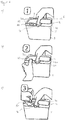
- Figure 1 shows three different phases (phase 1, phase 2 and phase 3) of an opening process of the closure device 10.
- the closure device 10 comprises a frame 20 and a lid 30.
- the frame 20 is fastened to a container 5 which is open at the top.
- Figure 1a shows the lid 30 in a closed position. In this closed position, the cover 30 bears against the frame 10 and closes an opening which is defined by the frame. In the in Figure 1a Phase 1 of the opening process shown, the container 5 is thus still closed.
- the closure device 10 further comprises a first closure means 40 and a second closure means 50.
- the closure means 40, 50 are arranged on one side of the essentially rectangular closure device 10. This page can be referred to as the layout page and is in Figure 1a marked with 11. On one of the arrangement side 11 opposite pivot side 12 frames 20 and 30 are in the Figure 1 not recognizable film hinges connected together.
- the film hinges define a pivot axis 6 about which the lid 30 can be folded up when the closing means 40, 50 are in an open position (see Figure 1c ).
- phase 1 a user places the thumb of his right hand on the first closing means 40.
- the other fingers of the right hand grip behind the pivoting side 12 of the locking device 10. As will be described in more detail later, this can be achieved by an opening force exerted by the thumb open first closing means 40.
- phase 2 the user places the thumb of his left hand on the second closing means 50.
- the second closing means can be opened by an opening force in the direction of the pivoting side 12.
- the user continues to press the thumb of the right hand on the first closing means 40 so that it continues to hold its open position.
- phase 3 the user grips a lid section 51 of the second closing means 50 with the thumb and index finger, the thumb exerting a first holding force and the index finger exerting a second holding force.
- the thumb and forefinger thus clamp the cover section 51, which is connected to the cover 30, so firmly that the cover section 51 is in contact with the cover 30 pulls up. Since the thumb of the right hand continues to hold the first closing means 40 in the open position, the lid 30 can be folded up completely. In this case, the cover 30, as in FIG Figure 1c shown, slightly twist.
- phases 2 and 3 can also be combined into a common phase.
- the lid section 51 of the second closing means 50 is gripped with the thumb and index finger of the left hand and then moved in the direction of the pivot axis 6. As soon as the closing means 50 has thereby been opened, the cover section 51 can be pulled up.
- first closing means 40 is arranged approximately centrally on the arrangement side 11 of the closing device 10.
- the second closing means 50 is also provided at a distance of about 6 cm.
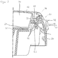
- Figure 2 shows a possible embodiment for the first closing means 40 in section.
- Figure 2 also shows the cover 30 and the frame 20.
- the cover 30 has a lower cover 31, which rests on a support surface 21 of the frame 20.
- the cover 30 has a substantially circumferential upper edge 32, a slightly inclined connecting wall 33 extending between the cover base 31 and the upper edge 32.
- the first closing means 40 has a cover section 41 and a frame section 42.
- the cover section 41 comprises a latching hook 43, which in the in Figure 2 shown position engages behind a locking undercut 44.
- the undercut 44 is formed by a web 45 which is formed in one piece with the frame 20. If an opening force now acts on a pressure area identified by 46 (see arrow 47), the web 45 becomes the pressure area 46 in the illustration of FIG Figure 2 pushed to the left. In this way, the locking between latching hook 41 and latching undercut 44 can be released.
- the closure means 40 is unlocked, the cover 30 can be folded upwards, provided the second closure means 50 has also been opened.
- the opening force 47 becomes when the opening process of the Figure 1 based on the thumb generated by the user's right hand.
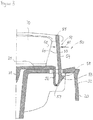
- FIG 3 shows an embodiment for the second closing means 50 in section.
- the closure means 50 has the lid section 51 already mentioned, which is made in one piece with the lid 30, and a frame section 52, which can also be understood as part of the frame 20.
- the cover section 51 comprises a latching hook 53 and a tab 54 connected to it.
- the tab 54 has an open end 55 and is at an opposite end to the latching hook 53 connected.
- a flexible connecting piece 56 is provided between the locking hook 53 and the cover base 31, which defines a pivot axis 57 for the locking hook 53.
- the pivot axis 57 is located below the lid base 31 and is also arranged below the locking hook 53. In the in Figure 3 illustrated position of the locking hook 53 there is a locking connection between locking hook 53 and a locking undercut 58.
- the tab 54 has a front side 59 and a rear side 60, the front side 59 forming a pressure surface and the rear side 60 forming a counter pressure surface. Judging from the opening process of the Figure 1 , whereby phase 2 and phase 3 can also be carried out together, the thumb of the left hand is placed on the front 59 and the index finger of the left hand is placed on the back 60. The thumb can then be used to open an opening force (see arrow 61 ) Apply to the tab 54, whereby the tab 54 and also the locking hook 53 attached to it in the representation of the Figure 3 be moved to the left. At a certain point, the latching hook 53 no longer engages behind the latching undercut 58, so that the tab 54 and thus also the cover 30 can be pulled upwards.
- a first holding force acts on the front side 59 (again here again see arrows 61) and a second holding force acts on the rear side 60 (see arrow 62), which is directed counter to the first holding force.
Landscapes
- Engineering & Computer Science (AREA)
- Mechanical Engineering (AREA)
- Closures For Containers (AREA)
Description
- Die Erfindung betrifft eine Verschlussvorrichtung, die einen eine Öffnung definierenden Rahmen, einen Deckel, der in einer geschlossenen Stellung die Öffnung überdeckt, und ein erstes Verschließmittel sowie mindestens ein zweites Verschließmittel aufweist. Die Verschließmittel dienen dazu, den Deckel in der geschlossenen Stellung zu halten.
- Es ist heute üblich, Wirksubstanzen, beispielsweise aus der Gruppe der Textilwaschmittel, Geschirrspülmittel, Pharmazeutika, Körperpflegemittel, Agrarhilfsmittel, Baustoffe, Farbstoffe, Klebstoffe oder Lebensmittel, in einer fließ- oder schüttfähigen Form oder auch als vordosierte Mengen zu verwenden, die z.B. als vordosierte Einheiten in einem Behälter bevorratet werden. Im Bereich der Bevorratung von handelsüblichen Mengen dieser Wirksubstanzen sind Kunststoffbehälter, die unter anderem transparent sein können, bekannt.
- Diese Behälter weisen besagte Verschlussvorrichtung auf, wobei der Rahmen der Verschlussvorrichtung an dem Behälter befestigt ist oder auch einstückig an diesem angeformt sein kann. Durch den Deckel der Verschlussvorrichtung lässt sich der Behälter dann entsprechend verschließen.
- Die Verschließmittel sollen den Deckel in der geschlossenen Stellung am Rahmen halten, selbst wenn äußere, unbeabsichtigte Kräfte auf den Rahmen oder auf den Deckel einwirken. Diese Kräfte können die Verschlussvorrichtung elastisch verformen und im ungünstigsten Falle die Verschlussvorrichtung unerwünscht öffnen. Solche Kräfte können z. B. während des Transports auftreten, oder aber im Rahmen einer Fehlhandhabung, falls beispielsweise ein Kind den Deckel in einer nicht vorgesehenen Weise zu öffnen versucht. Insofern besteht ein Bedarf, einerseits die geschlossene Stellung der Verschlussvorrichtung sicher auszulegen, andererseits die bestimmungsgemäße Öffnung der Verschlussvorrichtung nicht unnötig zu erschweren. Dazu müssen die Verschließmittel u. a. einfach bedienbar sein, um den Deckel in einer vorgesehenen Weise öffnen zu können.
- Aus der
WO 2001/48757 A1 WO 2001/48757 A1 - Eine kindersichere Verschlussvorrichtung mit den Merkmalen des Oberbegriffs des Anspruchs 1 ist ferner aus
DE 80 30 265 U bekannt. -
US 5,526,953 ,US 5,322,178 undUS 2010/264156 A1 beschreiben Behälter mit jeweils einzeln angeordneten, einfach zu handhabenden Verschlussvorrichtungen. - Der Erfindung liegt die Aufgabe zu Grunde, eine Verschlussvorrichtung mit Deckel, Rahmen und wenigstens zwei Verschließmittel bereitzustellen, die einen gewissen Schutz gegen ein unbeabsichtigtes Öffnen des Deckels bietet, aber gleichzeitig einfach zu handhaben und einfach bestimmungsgemäß zu öffnen ist.
- Die der Erfindung zu Grunde liegende Aufgabe wird mit der Merkmalskombination gemäß Anspruch 1 gelöst. Ausführungsbeispiele der Erfindung können den Unteransprüchen entnommen werden.
- Die erfindungsgemäße Verschlussvorrichtung zeichnet sich dadurch aus, dass der Deckelabschnitt des zweiten Verschließmittels eine Druckfläche und eine Gegendruckfläche aufweist, wobei die Druckfläche als Anlagefläche für die Öffnungskraft bzw. für eine erste Haltekraft dient. Die Gegendruckfläche dient als Anlagefläche für eine der ersten Haltekraft entgegen gesetzte zweite Haltekraft. Der Deckelabschnitt lässt sich die durch die Haltekräfte derart fixieren oder einklemmen, dass eine im Wesentlichen quer zu den Haltekräften gerichtete Schwenkkraft zum Herausschwenken des Deckels aus der geschlossenen Stellung über die Druckfläche und die Gegendruckfläche in den Deckelabschnitt eingeleitet werden kann.
- Die in der nachveröffentlichten
WO 2014/111 284 A1 beschriebene Verschlussvorrichtung hat keine solche Gegendruckfläche an einem ihrer Verschließmittel. - Die Verschlussvorrichtung kann nur dann ordnungsgemäß geöffnet werden, wenn sich das erste Verschließmittel und auch das zweite Verschließmittel in einer geöffneten Stellung befinden. Um das zweite Verschließmittel in die geöffnete Stellung zu bringen, wird über die Druckfläche die Öffnungskraft in den Deckelabschnitt eingeleitet. Zunächst wird das zweite Verschließmittel in die geöffnete Stellung überführt, wobei die die zweite Haltekraft gleich null oder verhältnismäßig klein sein. Danach wirken auf den Deckelabschnitt über die Fläche und die Gegendrucksfläche die erste und die zweite Haltekraft, wobei diese Haltekräfte betraglich in etwa gleich groß sind. Durch die Haltekräfte wird der Deckelabschnitt bzw. ein Teil des Deckelabschnitts eingeklemmt oder fixiert. Dadurch ist es möglich, den Deckelabschnitt quer zu den Haltekräften in eine Richtung ziehen, so dass der Deckel aus seiner geschlossenen Stellung geschwenkt wird.
- Als Druckfläche ist hier eine Fläche zu verstehen, die mit einem Finger einer menschlichen Hand des Nutzers betätigt werden kann. Die Druckfläche kann Erhebungen, Vertiefungen oder sonstige Hilfsmittel aufweisen, um bessere Hafteigenschaften des anliegenden Fingers zu bieten. Zudem können die Druckflächen geeignete Markierungen aufweisen, die das Auffinden der Druckfläche erleichtert. Gleiches gilt sinngemäß für die Gegendruckfläche.
- Es kann vorgesehen sein, dass zumindest eines der Verschließmittel einen Originalitätsverschluss umfasst. Weiterhin ist bevorzugt, dass dieses Verschließmittel eine zurückgesetzte Druckfläche umfasst, so dass der Originalitätsverschluss mit einem Außenwandbereich des Rahmens oder des Deckels, bevorzugt des Deckels, ebenflächig ist, d.h. sich in derselben Ebene befindet. Der Originalitätsverschluss ist derart konfiguriert, dass er vor einem ersten Öffnen des Deckels, mindestens teilweise abgebrochen, bevorzugt völlig von der Verschlussvorrichtung abgetrennt werden muss.
- In einem Ausführungsbeispiel sind die Verschließmittel so ausgeführt und angeordnet, dass eine gleichzeitige Betätigung der zwei Verschließmittel in der Regel nur mit beiden Händen eines Nutzers möglich ist. Die Verschlussvorrichtung kann grundsätzlich neben dem ersten und zweiten Verschließmittel auch weitere Verschließmittel umfassen. Die Öffnungskräfte für das erste und zweite Verschließmittel und gegebenenfalls für weitere Verschließmittel sind dabei jeweils unabhängig voneinander. Daraus folgt, dass die Verschlussvorrichtung nicht in unbeabsichtigter Weise, beispielsweise durch Kinder leicht geöffnet werden kann.
- Das erste Verschließmittel und/oder das zweite Verschließmittel können als Rastverbindung ausgebildet sein. Entsprechend kann der Deckelabschnitt des zweiten Verschließmittels einen Rasthaken aufweisen, der in einer Verriegelungsposition einen Rasthinterschnitt des Rahmenabschnitts des zweiten Verschließmittels hintergreift.
- Der Deckelabschnitt des zweiten Verschließmittels kann eine Lasche mit einer Vorderseite und einer Rückseite aufweisen, wobei die Vorderseite die Druckfläche und die Rückseite die Gegendruckfläche ausbilden und wobei der Rasthaken an der Lasche angeformt ist. Um das zweite Verschließmittel in seine geöffnete Stellung zu überführen, wirkt zunächst auf die Druckfläche der Lasche die Öffnungskraft, wodurch der Rasthaken aus seiner Verriegelungsposition bewegt wird. Dabei kann bereits auf die Gegendruckfläche eine gewisse Gegenkraft wirken, so dass die Lasche beispielsweise durch Daumen und Zeigefinger einer Hand des Nutzers festgehalten wird. Durch Ziehen der Lasche mit Daumen und Zeigefinger kann dann der Deckelabschnitt und damit der Deckel aus der geschlossenen Stellung herausgeschwenkt werden.
- In einem Ausführungsbeispiel ist die Lasche mit dem Rest des Deckels über ein flexibles Verbindungsstück verbunden, das eine Schwenkachse für den Rasthaken definiert. Vorzugsweise ist der Rasthaken zwischen Schwenkachse und dem Rasthinterschnitt angeordnet. Der Abstand zwischen einem oberen offenen Ende der Lasche und dem Rasthaken (Bezug soll die Rastfläche des Rasthakens sein) kann 1 bis 5 cm betragen, vorzugsweise 1,5 bis 3 cm. Greift am oberen Ende die Öffnungskraft an, so wird die Lasche gebogen und der Rasthaken aus seiner Verriegelungsposition geschoben. Diese Öffnungskraft kann Werte zwischen 5 bis 15 N, vorzugsweise 8 bis 10 N annehmen. Die Schwenkkraft, also die Zugkraft, um bei entriegeltem Rasthaken den Deckelabschnitt und somit den Deckel aus seiner geschlossenen Stellung zu schwenken, kann Werte zwischen 1 bis 10 N, vorzugsweise 1 bis 5 N annehmen. Die Öffnungskraft für das erste Verschließmittel kann 1 bis 30 N, vorzugsweise 3 bis 8 N betragen.
- Das erste Verschließmittel und das zweite Verschließmittel können auf einer Anordnungsseite der Verschlussvorrichtung angeordnet sein. Vorzugsweise ist die Anordnungsseite gegenüber der Schwenkachse angeordnet. Das erste Verschließmittel und das zweite Verschließmittel können auch an Seiten der Verschlussvorrichtung angeordnet sein, die an der Seite mit der Schwenkachse angrenzen. Auch ist es möglich, dass das erste Verschließmittel und das zweite Verschließmittel über Eck, also an zwei eine Ecke bildenden Seiten vorgesehen sind.
- In einem Ausführungsbeispiel ist ein Abstand zwischen dem ersten Verschließmittel und dem zweiten Verschließmittel kleiner als 15 cm. Vorzugsweise liegt der Abstand in einem Bereich zwischen 3 und 8 cm.
- Der Deckel und der Rahmen können als ein einteiliges Bauteil ausgeführt sein. Rahmen und Deckel können dabei über mindestes ein Filmscharnier miteinander verbunden sein. Die Verschlussvorrichtung lässt sich somit in einer Spritzgussform als kostengünstiges Kunststoffteil herstellen. Deckel und Rahmen können auch bei einer mehrteiligen Ausführung aus gleichem oder unterschiedlichem Kunststoff sein.
- Als Kunststoff kann jedes geeignete Kunststoffmaterial verwendet werden, bevorzugt sind Kunststoffe ausgewählt aus der Gruppe der Polyolefine. Besonders bevorzugt sind folgende Kunststoffe aus der Klasse der Polypropylene; Polyethylene; Polypropylen enthaltende Blends; Polyethylen enthaltende Blends; Polypropylen enthaltende Co-Polymere und/oder Random Co-Polymere; Polyethylen enthaltende Co-Polymere .
- Vorzugsweise ist der Deckel gefärbt. Falls der Deckel und der Rahmen einteilig sind, wird weiterhin bevorzugt, dass Deckel und Rahmen aus demselben, gefärbten Kunststoff hergestellt sind.
- Durch das Filmscharnier kann eine stabile geöffnete Stellung des Deckels definiert sein. Dadurch soll vermieden werden, dass, wenn der Deckel nach erfolgter Entriegelung der Verschließmittel geöffnet worden ist, nicht ohne weiteres unbeabsichtigt wieder in seine geschlossene Stellung zurückklappen kann. Beispielsweise kann das Filmscharnier mit einer Totpunktkinematik ausgebildet sein, bei der eine gewisse Kraft überwunden werden muss, um den Deckel aus der stabilen geöffneten Stellung in die geschlossene Stellung zu klappen.
- Die Verschlussvorrichtung wird vorzugsweise für einen Behälter für Wasch- und Reinigungsmittel verwendet. Somit ist ein Behälter mit Wasch- und Reinigungsmittel und mit einer Verschlussvorrichtung offenbart, wobei letztgenannte gemäß den hier beschriebenen Ausführungsbeispielen ausgeführt sein kann. Die Wasch- und/oder Reinigungsmittel können vorportionierte Wasch- und/oder Reinigungsmittel sein, die in mindestens einen lateralen Maß gleich oder mehr als 31,7 mm messen und bevorzugt nicht in einem Zylinder nach ISO Norm 8124-1 (zweite Edition, datiert 2009-03-15), 5.2 passen und somit den "Small parts test" bestehen.
- Anhand von den in der Zeichnung dargestellten Ausführungsbeispielen wird die Erfindung näher erläutert. Es zeigen:
- Figur 1
- einen Behälter mit einer erfindungsgemäßen Verschlussvorrichtung, wobei
Figur 1 verschiedene Phasen a), b) und c) des Öffnungsvorgangs der Verschlussvorrichtung zeigt; - Figur 2
- einen Querschnitt eines ersten Verschließmittels; und
- Figur 3
- einen Querschnitt eines zweiten Verschließmittels.
- Mit Hilfe von
Figur 1 soll die grundsätzliche Funktionsweise einer erfindungsgemäßen Verschlussvorrichtung 10 beschrieben werden.Figur 1 zeigt drei unterschiedliche Phasen (Phase 1, Phase 2 und Phase 3) eines Öffnungsvorgangs der Verschlussvorrichtung 10. - Die Verschlussvorrichtung 10 umfasst einen Rahmen 20 und einen Deckel 30. Der Rahmen 20 ist dabei an einem nach oben offenen Behälter 5 befestigt.
Figur 1a zeigt den Deckel 30 in einer geschlossenen Stellung. In dieser geschlossenen Stellung liegt der Deckel 30 an dem Rahmen 10 an und verschließt eine Öffnung, die durch den Rahmen definiert wird. In der inFigur 1a gezeigten Phase 1 des Öffnungsvorgangs ist somit der Behälter 5 noch verschlossen. - Die Verschlussvorrichtung 10 umfasst des Weiteren ein erstes Verschließmittel 40 und ein zweites Verschließmittel 50. Die Verschließmittel 40, 50 sind an einer Seite der im Wesentlichen rechtwinkligen Verschlussvorrichtung 10 angeordnet. Diese Seite kann als Anordnungsseite bezeichnet werden und ist in
Figur 1a mit 11 gekennzeichnet. An einer der Anordnungsseite 11 gegenüberliegenden Schwenkseite 12 sind Rahmen 20 und 30 über in derFigur 1 nicht erkennbare Filmscharniere miteinander verbunden. Die Filmscharniere definieren eine Schwenkachse 6, um die der Deckel 30 nach oben geklappt werden kann, wenn die Verschließmittel 40, 50 sich in einer geöffneten Stellung befinden (sieheFigur 1c ). - In der Phase 1 setzt ein Nutzer den Daumen seiner rechten Hand an das erste Verschließmittel 40. Die übrigen Finger der rechten Hand hintergreifen dabei die Schwenkseite 12 der Verschlussvorrichtung 10. Wie später noch näher beschrieben wird, lässt sich durch eine durch den Daumen ausgeübte Öffnungskraft das erste Verschließmittel 40 öffnen.
- In der Phase 2 (siehe
Figur 1b ) setzt der Nutzer den Daumen seiner linken Hand an das zweite Verschließmittel 50. Durch eine Öffnungskraft in Richtung der Schwenkseite 12 lässt sich das zweite Verschließmittel öffnen. In der Phase 2 drückt der Nutzer weiterhin den Daumen der rechten Hand auf das erste Verschließmittel 40, damit dieses weiterhin seine geöffnete Stellung beibehält. - In der Phase 3 (siehe
Figur 1c ) greift der Nutzer mit dem Daumen und Zeigefinger einen Deckelabschnitt 51 des zweiten Verschließmittels 50, wobei der Daumen eine erste Haltekraft und der Zeigefinger eine zweite Haltekraft ausüben. Daumen und Zeigefinger klemmen also den Deckelabschnitt 51, der mit dem Deckel 30 verbunden ist, so fest, dass sich der Deckelabschnitt 51 mit dem Deckel 30 nach oben ziehen lässt. Da der Daumen der rechten Hand weiterhin das erste Verschließmittel 40 in der geöffneten Stellung hält, kann der Deckel 30 vollständig nach oben geklappt werden. Dabei kann durch gewisse Reibkräfte oder Klemmkräfte zwischen Rahmen 20 und Deckel 30 sich der Deckel 30, wie inFigur 1c dargestellt, leicht verwinden. - Es sei darauf hingewiesen, dass die Phase 2 und 3 auch zu einer gemeinsamen Phase vereint werden können. In diesem Fall wird der Deckelabschnitt 51 des zweiten Verschließmittels 50 mit Daumen und Zeigefinger der linken Hand gegriffen und dann in Richtung der Schwenkachse 6 bewegt. Sobald dadurch das Verschließmittel 50 geöffnet worden ist, kann der Deckelabschnitt 51 hochgezogen werden.
- Wie der
Figur 1 zu entnehmen ist, ist das erste Verschließmittel 40 in etwa mittig an der Anordnungsseite 11 der Verschlussvorrichtung 10 angeordnet. In einem Abstand von ca. 6 cm ist daneben das zweite Verschließmittel 50 vorgesehen. - In den folgenden Figuren werden Merkmale oder Bauteile, die mit den Merkmalen oder Bauteile der Figur ein ähnlich oder identisch sind, mit gleichen Bezugszeichen versehen.
-
Figur 2 zeigt eine mögliche Ausführung für das erste Verschließmittel 40 im Schnitt.Figur 2 zeigt auch den Deckel 30 und den Rahmen 20. Der Deckel 30 weist einen tiefer bezogenen Deckelboden 31 auf, der auf einer Auflagefläche 21 des Rahmens 20 aufliegt. Der Deckel 30 weist eine im Wesentlichen umlaufende obere Kante 32 auf, wobei sich zwischen Deckelboden 31 und oberer Kante 32 eine leicht geneigte Verbindungswand 33 erstreckt. - Das erste Verschließmittel 40 weist einen Deckelabschnitt 41 und einen Rahmenabschnitt 42 auf. Der Deckelabschnitt 41 umfasst einen Rasthaken 43, der in der in
Figur 2 dargestellten Stellung einen Rasthinterschnitt 44 hintergreift. Der Hinterschnitt 44 wird durch einen Steg 45 gebildet, welcher einstückig mit dem Rahmen 20 ausgebildet ist. Wirkt nun auf eine mit 46 gekennzeichnete Druckfläche eine Öffnungskraft (siehe Pfeil 47), so wird mit der Druckfläche 46 der Steg 45 in der Darstellung derFigur 2 nach links gedrückt. Somit lässt sich die Verriegelung zwischen Rasthaken 41 und Rasthinterschnitt 44 lösen. Bei entriegeltem Verschließmittel 40, lässt sich, soweit das zweite Verschließmittel 50 ebenfalls geöffnet worden ist, der Deckel 30 nach oben klappen. Die Öffnungskraft 47 wird, wenn man den Öffnungsvorgang derFigur 1 zugrundelegt, durch den Daumen der rechten Hand des Nutzers erzeugt. -
Figur 3 zeigt eine Ausführung für das zweite Verschließmittel 50 im Schnitt. Das Verschließmittel 50 weist den bereits oben erwähnten Deckelabschnitt 51, der einstückig mit dem Deckel 30 ausgeführt ist, und einen Rahmenabschnitt 52 auf, der auch als Teil des Rahmens 20 aufgefasst werden kann. Der Deckelabschnitt 51 umfasst einen Rasthaken 53 und eine damit verbundene Lasche 54. Die Lasche 54 weist ein offenes Ende 55 auf und ist an einem gegenüberliegenden Ende mit dem Rasthaken 53 verbunden. Zwischen dem Rasthaken 53 und dem Deckelboden 31 ist ein flexibles Verbindungsstück 56 vorgesehen, dass eine Schwenkachse 57 für den Rasthaken 53 definiert. Die Schwenkachse 57 liegt dabei unterhalb des Deckelbodens 31 und ist auch unterhalb des Rasthakens 53 angeordnet. In der inFigur 3 dargestellten Position des Rasthakens 53 besteht eine Rastverbindung zwischen Rasthaken 53 und einem Rasthinterschnitt 58. - Die Lasche 54 weist eine Vorderseite 59 und eine Rückseite 60 auf, wobei die Vorderseite 59 eine Druckfläche und die Rückseite 60 eine Gegendruckfläche ausbilden sollen. Geht man von dem Öffnungsvorgang der
Figur 1 aus, wobei Phase 2 und Phase 3 auch gemeinsam durchgeführt werden können, so wird der Daumen der linken Hand an die Vorderseite 59 gesetzt und der Zeigefinger der linken Hand entsprechend an die Rückseite 60. Durch den Daumen lässt sich dann eine Öffnungskraft (siehe Pfeil 61) auf die Lasche 54 aufbringen, wodurch die Lasche 54 und auch der daran befestigte Rasthaken 53 in der Darstellung derFigur 3 nach links bewegt werden. Ab einem bestimmten Punkt hintergreift der Rasthaken 53 nicht mehr den Rasthinterschnitt 58, so dass die Lasche 54 und somit auch der Deckel 30 nach oben gezogen werden kann. Dabei müssen Daumen und Zeigefinger der linken Hand die Lasche 54 mit einer gewissen Kraft einklemmen. Entsprechend wirkt auf die Vorderseite 59 eine erste Haltekraft (auch hier wieder siehe Pfeile 61) und auf die Rückseite 60 eine zweite Haltekraft (siehe Pfeil 62), die der ersten Haltekraft entgegen gerichtet ist. -
- 5
- Behälter
- 6
- Schwenkachse
- 10
- Verschlussvorrichtung
- 11
- Anordnungsseite
- 12
- Schwenkseite
- 20
- Rahmen
- 21
- Auflagefläche
- 30
- Deckel
- 31
- Deckelboden
- 32
- umlaufende Kante
- 33
- Verbindungswand
- 40
- erstes Verschließmittel
- 41
- Deckelabschnitt
- 42
- Rahmenabschnitt
- 43
- Rasthaken
- 44
- Rasthinterschnitt
- 45
- Steg
- 46
- Druckfläche
- 47
- Pfeil "Öffnungskraft"
- 50
- zweites Verschließmittel
- 51
- Deckelabschnitt
- 52
- Rahmenabschnitt
- 53
- Rasthaken
- 54
- Lasche
- 55
- oberes Ende
- 56
- Verbindungsstück
- 57
- Schwenkachse
- 58
- Rasthinterschnitt
- 59
- Vorderseite
- 60
- Rückseite
- 61
- Pfeil "erste Haltekraft"
- 62
- Pfeil "zweite Haltekraft"
Claims (12)
- Verschlussvorrichtung (10) umfassend einen eine Öffnung definierenden Rahmen (20), einen die Öffnung überdeckenden Deckel (30), der über eine an einer Seite des Rahmens angeordnete Schwenkachse (6) schwenkbar an den Rahmen (20) gekoppelt ist, und ein erstes Verschließmittel (40) sowie zumindest ein zweites, von dem ersten Verschließmittel (40) beabstandetes zweites Verschließmittel (50), wobei die Verschließmittel (40, 50) dazu dienen, den Deckel in einer geschlossenen Stellung zu halten, und jeweils einen Deckelabschnitt (41, 51) und einen Rahmenabschnitt (42, 52) aufweisen, wobei das erste Verschließmittel (40) durch direkte Einwirkung einer Öffnungskraft (47) auf den zugeordneten Rahmenabschnitt (42) geöffnet werden kann und das zweite Verschließmittel (50) durch direkte Einwirkung einer Öffnungskraft bzw. ersten Haltekraft (61) auf den zugeordneten Deckelabschnitt (51) geöffnet werden kann, wobei der Deckelabschnitt (51) des zweiten Verschließmittels (50) eine Druckfläche (Vorderseite 59) aufweist, die als Anlagefläche für die erste Haltekraft (61) dient, dadurch gekennzeichnet, dass der Deckelabschnitt (51) des zweiten Verschließmittels (50) ferner eine Gegendruckfläche (Rückseite 60) aufweist, welche Gegendruckfläche als Anlagefläche für eine der ersten Haltekraft (61) entgegen gesetzte zweite Haltekraft (62) dient, wobei der Deckelabschnitt (51) durch die Haltekräfte derart fixierbar ist, dass eine im Wesentlichen quer zu den Haltekräfte wirkende Schwenkkraft zum Herausschwenken des Deckels (30) aus der geschlossenen Stellung über Druckfläche (Vorderseite 59) und Gegendruckfläche (Rückseite 60) in den Deckelabschnitt (51) einleitbar ist.
- Verschlussvorrichtung (10) nach Anspruch 1, dadurch gekennzeichnet, dass der Deckelabschnitt (51) des zweiten Verschließmittels (50) einen Rasthaken (53) aufweist, der in einer Verriegelungsposition einen Rasthinterschnitt (58) des Rahmenabschnitts (52) des zweiten Verschließmittels (50) hintergreift.
- Verschlussvorrichtung (10) nach Anspruch 2, dadurch gekennzeichnet, dass der Deckelabschnitt (51) des zweiten Verschließmittels (50) eine Lasche (54) mit der Vorderseite (59) und der Rückseite (60) aufweist, wobei die Vorderseite (59) die Druckfläche und die Rückseite (60) die Gegendruckfläche ausbilden und wobei der Rasthaken (53) an der Lasche (54) angeformt ist.
- Verschlussvorrichtung (10) nach Anspruch 3, dadurch gekennzeichnet, dass die Lasche (54) mit dem Deckel (30) über ein flexible Verbindungsstück (56) verbunden ist, das eine Schwenkachse (57) für den Rasthaken (53) definiert.
- Verschlussvorrichtung (10) nach Anspruch 4, dadurch gekennzeichnet, dass der Rasthaken (53) zwischen Schwenkachse (57) und dem Rasthinterschnitt (58) angeordnet ist.
- Verschlussvorrichtung (10) nach einem der vorangegangenen Ansprüche, dadurch gekennzeichnet, dass das erste Verschließmittel (40) und das zweite Verschließmittel (50) auf einer Anordnungsseite (11) der Verschlussvorrichtung (10) angeordnet sind.
- Verschlussvorrichtung (10) nach Anspruch 6, dadurch gekennzeichnet, dass die Anordnungsseite (11) gegenüberliegend der Schwenkachse (6) angeordnet ist.
- Verschlussvorrichtung (10) nach einem der vorangegangenen Ansprüche, dadurch gekennzeichnet, dass ein Abstand zwischen dem ersten Verschließmittel (40) und dem zweiten Verschließmittel (50) kleiner als 15 cm ist.
- Verschlussvorrichtung (10) nach einem der vorangegangenen Ansprüche, dadurch gekennzeichnet, dass der Deckel (30) und der Rahmen (20) der Verschlussvorrichtung (10) als ein einteiliges Bauteil ausgeführt sind.
- Verschlussvorrichtung (10) nach einem der vorangegangenen Ansprüche, dadurch gekennzeichnet, dass der Rahmen (20) und der Deckel (30) durch ein Filmscharnier verschwenkbar miteinander verbunden sind.
- Verschlussvorrichtung (10) nach Anspruch 10, dadurch gekennzeichnet, dass durch das Filmscharnier eine stabile geöffnete Stellung des Deckels (30) definiert ist.
- Behälter mit einer Verschlussvorrichtung nach einer der Ansprüche 1 bis 11.
Applications Claiming Priority (2)
| Application Number | Priority Date | Filing Date | Title |
|---|---|---|---|
| DE102013226962.5A DE102013226962A1 (de) | 2013-12-20 | 2013-12-20 | Verschlussvorrichtung |
| PCT/DE2014/200291 WO2015090289A1 (de) | 2013-12-20 | 2014-07-01 | Verschlussvorrichtung für schwenkdeckelbehälter |
Publications (2)
| Publication Number | Publication Date |
|---|---|
| EP3083427A1 EP3083427A1 (de) | 2016-10-26 |
| EP3083427B1 true EP3083427B1 (de) | 2020-02-19 |
Family
ID=51263166
Family Applications (1)
| Application Number | Title | Priority Date | Filing Date |
|---|---|---|---|
| EP14746943.1A Active EP3083427B1 (de) | 2013-12-20 | 2014-07-01 | Verschlussvorrichtung für schwenkdeckelbehälter |
Country Status (4)
| Country | Link |
|---|---|
| US (1) | US20170203889A1 (de) |
| EP (1) | EP3083427B1 (de) |
| DE (1) | DE102013226962A1 (de) |
| WO (1) | WO2015090289A1 (de) |
Families Citing this family (9)
| Publication number | Priority date | Publication date | Assignee | Title |
|---|---|---|---|---|
| DE102016215846A1 (de) | 2016-08-23 | 2018-03-01 | Henkel Ag & Co. Kgaa | Verschlussvorrichtung und Behälter mit einer solchen Verschlussvorrichtung |
| US10759576B2 (en) * | 2016-09-28 | 2020-09-01 | The Procter And Gamble Company | Closure interlocking mechanism that prevents accidental initial opening of a container |
| DE102016222205A1 (de) | 2016-11-11 | 2018-05-17 | Henkel Ag & Co. Kgaa | Verschlussvorrichtung und Behälter mit einer solchen Verschlussvorrichtung |
| PL3483087T3 (pl) * | 2017-11-08 | 2021-05-17 | The Procter & Gamble Company | Produkt konsumencki |
| US10934064B2 (en) | 2017-11-08 | 2021-03-02 | The Procter & Gamble Company | Consumer product that includes a container and unit dose articles |
| EP3489164B1 (de) | 2017-11-23 | 2023-01-25 | The Procter & Gamble Company | Verschluss für einen behälter mit drei positionen |
| EP3489165B1 (de) | 2017-11-23 | 2022-08-17 | The Procter & Gamble Company | Verschluss für einen behälter mit einem asymmetrischen vorsprung |
| US12351373B2 (en) * | 2021-05-12 | 2025-07-08 | Paul Bradley Forrest | Releasable container cap |
| US11542067B2 (en) * | 2021-05-12 | 2023-01-03 | Paul Bradley Forrest | Releasable container cap |
Family Cites Families (15)
| Publication number | Priority date | Publication date | Assignee | Title |
|---|---|---|---|---|
| DE8030265U1 (de) * | 1980-11-13 | 1981-03-12 | Max Hübner GmbH & Co, 8950 Kaufbeuren | Kindersicherer Verpackungsbehaelter |
| US4500008A (en) * | 1982-09-22 | 1985-02-19 | Pdl Industries Limited | Weatherproof and/or dust proof fitting |
| US4746008A (en) * | 1987-07-01 | 1988-05-24 | Heverly Karen H | Child-resistant box for storage of hazardous materials |
| US5322178A (en) * | 1993-04-21 | 1994-06-21 | Plastofilm Industries, Inc. | One-hand operable latch for tub type container |
| US5526953A (en) * | 1994-05-24 | 1996-06-18 | Chieng; Walter | Portable box for containing V8 video tapes |
| FR2803079B1 (fr) | 1999-12-23 | 2002-09-06 | Moulages De Velay | Boitier support de rangement pour disque compact audio ou video |
| US6729498B2 (en) * | 2001-06-29 | 2004-05-04 | The Procter & Gamble Company | Dispenser for wipes |
| US7549541B2 (en) * | 2005-07-26 | 2009-06-23 | Rexam Closure Systems Inc. | Child-resistant compact for blister card products |
| FR2913674B1 (fr) * | 2007-03-12 | 2009-05-08 | Sanofi Aventis Sa | Etui de protection d'un blister comportant des moyens de verrouillage automatique deverrouillables par torsion |
| GB0720679D0 (en) * | 2007-10-23 | 2007-12-05 | Meadwestvaco Corp | Closure for a container |
| US20090127156A1 (en) * | 2007-11-15 | 2009-05-21 | Yaotsung Tung | Child-Resistant Container for Housing a Blister Card |
| WO2009081050A2 (fr) * | 2007-12-19 | 2009-07-02 | Compagnie Gervais Danone | Emballage alimentaire avec couvercle et systeme de fermeture pour un emballage |
| US20110259783A1 (en) * | 2008-05-14 | 2011-10-27 | Karen Angelucci | Item dispenser with multi-section wells |
| GB0901806D0 (en) * | 2009-02-04 | 2009-03-11 | Archimedes Dev Ltd | A child resistant container |
| ES2655849T3 (es) * | 2013-01-16 | 2018-02-21 | Henkel Ag & Co. Kgaa | Recipiente con dispositivo de cierre |
-
2013
- 2013-12-20 DE DE102013226962.5A patent/DE102013226962A1/de not_active Withdrawn
-
2014
- 2014-07-01 WO PCT/DE2014/200291 patent/WO2015090289A1/de not_active Ceased
- 2014-07-01 EP EP14746943.1A patent/EP3083427B1/de active Active
-
2016
- 2016-06-17 US US15/185,252 patent/US20170203889A1/en not_active Abandoned
Non-Patent Citations (1)
| Title |
|---|
| None * |
Also Published As
| Publication number | Publication date |
|---|---|
| US20170203889A1 (en) | 2017-07-20 |
| WO2015090289A1 (de) | 2015-06-25 |
| EP3083427A1 (de) | 2016-10-26 |
| DE102013226962A1 (de) | 2015-06-25 |
Similar Documents
| Publication | Publication Date | Title |
|---|---|---|
| EP2945876B1 (de) | Behälter mit verschlussvorrichtung | |
| WO2015090289A1 (de) | Verschlussvorrichtung für schwenkdeckelbehälter | |
| AT507950B1 (de) | Deckel eines behälters | |
| DE60217758T2 (de) | Ausgabekapsel mit gesicherter Öffnung | |
| AT517655B1 (de) | Pipettenspitzen-Aufnahmebehälter sowie Verfahren zu dessen Bereitstellung | |
| EP1747151A1 (de) | Manipulationssicherer deckel | |
| CH623791A5 (de) | ||
| EP3504131B1 (de) | Verschlussvorrichtung und behälter mit einer solchen verschlussvorrichtung | |
| EP3647225B1 (de) | Deckel für einen behälter und essbesteck, das aus einem derartigen deckel hergestellt ist | |
| EP3218280A1 (de) | Verschlussvorrichtung und behälter | |
| WO2018086914A1 (de) | Verschlussvorrichtung und behälter mit einer solchen verschlussvorrichtung | |
| DE20118278U1 (de) | Taschenstempelbox | |
| EP0868360B1 (de) | Verschlusskappe | |
| EP3075676B1 (de) | Verpackungsbehälter mit angeformtem henkel | |
| EP2130042B1 (de) | Behälter für mehrere Teststreifen | |
| WO2007118438A1 (de) | Stopfen für einen behälter | |
| DE2329682C3 (de) | Sicherheitsverschluß aus Kunststoff | |
| DE1994352U (de) | Verschlussorgan aus kunststoff. | |
| DE9208457U1 (de) | Behälter zur Aufbewahrung eines Anstrichgerätes | |
| EP3083428B1 (de) | Klappdeckelverschluss für ein behältnis | |
| DE102021117341B3 (de) | Quetschbeutelvorrichtung und Griffeinrichtung | |
| DE102016106719A1 (de) | Einteilige Verschluss- und/oder Aufbewahrungsvorrichtung sowie Verfahren dazu | |
| DE1761121C3 (de) | Sicherheits-Verschlußdeckel für Behälter | |
| EP0094103A2 (de) | Kindergesicherter Messbecher | |
| DE202013007760U1 (de) | Behälter mit Laschen |
Legal Events
| Date | Code | Title | Description |
|---|---|---|---|
| PUAI | Public reference made under article 153(3) epc to a published international application that has entered the european phase |
Free format text: ORIGINAL CODE: 0009012 |
|
| 17P | Request for examination filed |
Effective date: 20160520 |
|
| AK | Designated contracting states |
Kind code of ref document: A1 Designated state(s): AL AT BE BG CH CY CZ DE DK EE ES FI FR GB GR HR HU IE IS IT LI LT LU LV MC MK MT NL NO PL PT RO RS SE SI SK SM TR |
|
| AX | Request for extension of the european patent |
Extension state: BA ME |
|
| DAX | Request for extension of the european patent (deleted) | ||
| GRAP | Despatch of communication of intention to grant a patent |
Free format text: ORIGINAL CODE: EPIDOSNIGR1 |
|
| STAA | Information on the status of an ep patent application or granted ep patent |
Free format text: STATUS: GRANT OF PATENT IS INTENDED |
|
| RIC1 | Information provided on ipc code assigned before grant |
Ipc: B65D 43/16 20060101AFI20190912BHEP Ipc: B65D 50/04 20060101ALI20190912BHEP Ipc: B65D 43/22 20060101ALI20190912BHEP Ipc: B65D 47/08 20060101ALI20190912BHEP |
|
| INTG | Intention to grant announced |
Effective date: 20191009 |
|
| GRAS | Grant fee paid |
Free format text: ORIGINAL CODE: EPIDOSNIGR3 |
|
| GRAA | (expected) grant |
Free format text: ORIGINAL CODE: 0009210 |
|
| STAA | Information on the status of an ep patent application or granted ep patent |
Free format text: STATUS: THE PATENT HAS BEEN GRANTED |
|
| AK | Designated contracting states |
Kind code of ref document: B1 Designated state(s): AL AT BE BG CH CY CZ DE DK EE ES FI FR GB GR HR HU IE IS IT LI LT LU LV MC MK MT NL NO PL PT RO RS SE SI SK SM TR |
|
| REG | Reference to a national code |
Ref country code: CH Ref legal event code: EP Ref country code: CH Ref legal event code: PK Free format text: BERICHTIGUNGEN |
|
| REG | Reference to a national code |
Ref country code: DE Ref legal event code: R096 Ref document number: 502014013649 Country of ref document: DE |
|
| REG | Reference to a national code |
Ref country code: AT Ref legal event code: REF Ref document number: 1234706 Country of ref document: AT Kind code of ref document: T Effective date: 20200315 |
|
| REG | Reference to a national code |
Ref country code: IE Ref legal event code: FG4D Free format text: LANGUAGE OF EP DOCUMENT: GERMAN |
|
| RIN2 | Information on inventor provided after grant (corrected) |
Inventor name: BUTTER-JENTSCH, RALPH Inventor name: BERTRAM, CARSTEN Inventor name: HENNING, INGOMAR |
|
| REG | Reference to a national code |
Ref country code: NL Ref legal event code: MP Effective date: 20200219 |
|
| PG25 | Lapsed in a contracting state [announced via postgrant information from national office to epo] |
Ref country code: RS Free format text: LAPSE BECAUSE OF FAILURE TO SUBMIT A TRANSLATION OF THE DESCRIPTION OR TO PAY THE FEE WITHIN THE PRESCRIBED TIME-LIMIT Effective date: 20200219 Ref country code: NO Free format text: LAPSE BECAUSE OF FAILURE TO SUBMIT A TRANSLATION OF THE DESCRIPTION OR TO PAY THE FEE WITHIN THE PRESCRIBED TIME-LIMIT Effective date: 20200519 Ref country code: FI Free format text: LAPSE BECAUSE OF FAILURE TO SUBMIT A TRANSLATION OF THE DESCRIPTION OR TO PAY THE FEE WITHIN THE PRESCRIBED TIME-LIMIT Effective date: 20200219 |
|
| REG | Reference to a national code |
Ref country code: LT Ref legal event code: MG4D |
|
| PG25 | Lapsed in a contracting state [announced via postgrant information from national office to epo] |
Ref country code: LV Free format text: LAPSE BECAUSE OF FAILURE TO SUBMIT A TRANSLATION OF THE DESCRIPTION OR TO PAY THE FEE WITHIN THE PRESCRIBED TIME-LIMIT Effective date: 20200219 Ref country code: SE Free format text: LAPSE BECAUSE OF FAILURE TO SUBMIT A TRANSLATION OF THE DESCRIPTION OR TO PAY THE FEE WITHIN THE PRESCRIBED TIME-LIMIT Effective date: 20200219 Ref country code: HR Free format text: LAPSE BECAUSE OF FAILURE TO SUBMIT A TRANSLATION OF THE DESCRIPTION OR TO PAY THE FEE WITHIN THE PRESCRIBED TIME-LIMIT Effective date: 20200219 Ref country code: IS Free format text: LAPSE BECAUSE OF FAILURE TO SUBMIT A TRANSLATION OF THE DESCRIPTION OR TO PAY THE FEE WITHIN THE PRESCRIBED TIME-LIMIT Effective date: 20200619 Ref country code: BG Free format text: LAPSE BECAUSE OF FAILURE TO SUBMIT A TRANSLATION OF THE DESCRIPTION OR TO PAY THE FEE WITHIN THE PRESCRIBED TIME-LIMIT Effective date: 20200519 Ref country code: GR Free format text: LAPSE BECAUSE OF FAILURE TO SUBMIT A TRANSLATION OF THE DESCRIPTION OR TO PAY THE FEE WITHIN THE PRESCRIBED TIME-LIMIT Effective date: 20200520 |
|
| PG25 | Lapsed in a contracting state [announced via postgrant information from national office to epo] |
Ref country code: NL Free format text: LAPSE BECAUSE OF FAILURE TO SUBMIT A TRANSLATION OF THE DESCRIPTION OR TO PAY THE FEE WITHIN THE PRESCRIBED TIME-LIMIT Effective date: 20200219 |
|
| PG25 | Lapsed in a contracting state [announced via postgrant information from national office to epo] |
Ref country code: RO Free format text: LAPSE BECAUSE OF FAILURE TO SUBMIT A TRANSLATION OF THE DESCRIPTION OR TO PAY THE FEE WITHIN THE PRESCRIBED TIME-LIMIT Effective date: 20200219 Ref country code: SK Free format text: LAPSE BECAUSE OF FAILURE TO SUBMIT A TRANSLATION OF THE DESCRIPTION OR TO PAY THE FEE WITHIN THE PRESCRIBED TIME-LIMIT Effective date: 20200219 Ref country code: LT Free format text: LAPSE BECAUSE OF FAILURE TO SUBMIT A TRANSLATION OF THE DESCRIPTION OR TO PAY THE FEE WITHIN THE PRESCRIBED TIME-LIMIT Effective date: 20200219 Ref country code: ES Free format text: LAPSE BECAUSE OF FAILURE TO SUBMIT A TRANSLATION OF THE DESCRIPTION OR TO PAY THE FEE WITHIN THE PRESCRIBED TIME-LIMIT Effective date: 20200219 Ref country code: CZ Free format text: LAPSE BECAUSE OF FAILURE TO SUBMIT A TRANSLATION OF THE DESCRIPTION OR TO PAY THE FEE WITHIN THE PRESCRIBED TIME-LIMIT Effective date: 20200219 Ref country code: DK Free format text: LAPSE BECAUSE OF FAILURE TO SUBMIT A TRANSLATION OF THE DESCRIPTION OR TO PAY THE FEE WITHIN THE PRESCRIBED TIME-LIMIT Effective date: 20200219 Ref country code: SM Free format text: LAPSE BECAUSE OF FAILURE TO SUBMIT A TRANSLATION OF THE DESCRIPTION OR TO PAY THE FEE WITHIN THE PRESCRIBED TIME-LIMIT Effective date: 20200219 Ref country code: EE Free format text: LAPSE BECAUSE OF FAILURE TO SUBMIT A TRANSLATION OF THE DESCRIPTION OR TO PAY THE FEE WITHIN THE PRESCRIBED TIME-LIMIT Effective date: 20200219 Ref country code: PT Free format text: LAPSE BECAUSE OF FAILURE TO SUBMIT A TRANSLATION OF THE DESCRIPTION OR TO PAY THE FEE WITHIN THE PRESCRIBED TIME-LIMIT Effective date: 20200712 |
|
| REG | Reference to a national code |
Ref country code: DE Ref legal event code: R097 Ref document number: 502014013649 Country of ref document: DE |
|
| PLBE | No opposition filed within time limit |
Free format text: ORIGINAL CODE: 0009261 |
|
| STAA | Information on the status of an ep patent application or granted ep patent |
Free format text: STATUS: NO OPPOSITION FILED WITHIN TIME LIMIT |
|
| 26N | No opposition filed |
Effective date: 20201120 |
|
| PG25 | Lapsed in a contracting state [announced via postgrant information from national office to epo] |
Ref country code: IT Free format text: LAPSE BECAUSE OF FAILURE TO SUBMIT A TRANSLATION OF THE DESCRIPTION OR TO PAY THE FEE WITHIN THE PRESCRIBED TIME-LIMIT Effective date: 20200219 |
|
| PG25 | Lapsed in a contracting state [announced via postgrant information from national office to epo] |
Ref country code: MC Free format text: LAPSE BECAUSE OF FAILURE TO SUBMIT A TRANSLATION OF THE DESCRIPTION OR TO PAY THE FEE WITHIN THE PRESCRIBED TIME-LIMIT Effective date: 20200219 Ref country code: SI Free format text: LAPSE BECAUSE OF FAILURE TO SUBMIT A TRANSLATION OF THE DESCRIPTION OR TO PAY THE FEE WITHIN THE PRESCRIBED TIME-LIMIT Effective date: 20200219 Ref country code: PL Free format text: LAPSE BECAUSE OF FAILURE TO SUBMIT A TRANSLATION OF THE DESCRIPTION OR TO PAY THE FEE WITHIN THE PRESCRIBED TIME-LIMIT Effective date: 20200219 |
|
| REG | Reference to a national code |
Ref country code: CH Ref legal event code: PL |
|
| REG | Reference to a national code |
Ref country code: BE Ref legal event code: MM Effective date: 20200731 |
|
| PG25 | Lapsed in a contracting state [announced via postgrant information from national office to epo] |
Ref country code: LU Free format text: LAPSE BECAUSE OF NON-PAYMENT OF DUE FEES Effective date: 20200701 Ref country code: CH Free format text: LAPSE BECAUSE OF NON-PAYMENT OF DUE FEES Effective date: 20200731 Ref country code: IE Free format text: LAPSE BECAUSE OF NON-PAYMENT OF DUE FEES Effective date: 20200701 Ref country code: LI Free format text: LAPSE BECAUSE OF NON-PAYMENT OF DUE FEES Effective date: 20200731 |
|
| PG25 | Lapsed in a contracting state [announced via postgrant information from national office to epo] |
Ref country code: BE Free format text: LAPSE BECAUSE OF NON-PAYMENT OF DUE FEES Effective date: 20200731 |
|
| REG | Reference to a national code |
Ref country code: AT Ref legal event code: MM01 Ref document number: 1234706 Country of ref document: AT Kind code of ref document: T Effective date: 20200701 |
|
| PG25 | Lapsed in a contracting state [announced via postgrant information from national office to epo] |
Ref country code: AT Free format text: LAPSE BECAUSE OF NON-PAYMENT OF DUE FEES Effective date: 20200701 |
|
| PG25 | Lapsed in a contracting state [announced via postgrant information from national office to epo] |
Ref country code: TR Free format text: LAPSE BECAUSE OF FAILURE TO SUBMIT A TRANSLATION OF THE DESCRIPTION OR TO PAY THE FEE WITHIN THE PRESCRIBED TIME-LIMIT Effective date: 20200219 Ref country code: MT Free format text: LAPSE BECAUSE OF FAILURE TO SUBMIT A TRANSLATION OF THE DESCRIPTION OR TO PAY THE FEE WITHIN THE PRESCRIBED TIME-LIMIT Effective date: 20200219 Ref country code: CY Free format text: LAPSE BECAUSE OF FAILURE TO SUBMIT A TRANSLATION OF THE DESCRIPTION OR TO PAY THE FEE WITHIN THE PRESCRIBED TIME-LIMIT Effective date: 20200219 |
|
| PG25 | Lapsed in a contracting state [announced via postgrant information from national office to epo] |
Ref country code: MK Free format text: LAPSE BECAUSE OF FAILURE TO SUBMIT A TRANSLATION OF THE DESCRIPTION OR TO PAY THE FEE WITHIN THE PRESCRIBED TIME-LIMIT Effective date: 20200219 Ref country code: AL Free format text: LAPSE BECAUSE OF FAILURE TO SUBMIT A TRANSLATION OF THE DESCRIPTION OR TO PAY THE FEE WITHIN THE PRESCRIBED TIME-LIMIT Effective date: 20200219 |
|
| P01 | Opt-out of the competence of the unified patent court (upc) registered |
Effective date: 20230705 |
|
| PGFP | Annual fee paid to national office [announced via postgrant information from national office to epo] |
Ref country code: DE Payment date: 20250722 Year of fee payment: 12 |
|
| PGFP | Annual fee paid to national office [announced via postgrant information from national office to epo] |
Ref country code: GB Payment date: 20250722 Year of fee payment: 12 |
|
| PGFP | Annual fee paid to national office [announced via postgrant information from national office to epo] |
Ref country code: FR Payment date: 20250725 Year of fee payment: 12 |
|
| REG | Reference to a national code |
Ref country code: DE Ref legal event code: R084 Ref document number: 502014013649 Country of ref document: DE |