EP3083339B1 - Serrure electronique pour une voiture - Google Patents
Serrure electronique pour une voiture Download PDFInfo
- Publication number
- EP3083339B1 EP3083339B1 EP14871760.6A EP14871760A EP3083339B1 EP 3083339 B1 EP3083339 B1 EP 3083339B1 EP 14871760 A EP14871760 A EP 14871760A EP 3083339 B1 EP3083339 B1 EP 3083339B1
- Authority
- EP
- European Patent Office
- Prior art keywords
- rotor
- unit
- lock unit
- electronic lock
- authentication
- Prior art date
- Legal status (The legal status is an assumption and is not a legal conclusion. Google has not performed a legal analysis and makes no representation as to the accuracy of the status listed.)
- Not-in-force
Links
Images


Classifications
-
- B—PERFORMING OPERATIONS; TRANSPORTING
- B60—VEHICLES IN GENERAL
- B60R—VEHICLES, VEHICLE FITTINGS, OR VEHICLE PARTS, NOT OTHERWISE PROVIDED FOR
- B60R25/00—Fittings or systems for preventing or indicating unauthorised use or theft of vehicles
- B60R25/01—Fittings or systems for preventing or indicating unauthorised use or theft of vehicles operating on vehicle systems or fittings, e.g. on doors, seats or windscreens
- B60R25/02—Fittings or systems for preventing or indicating unauthorised use or theft of vehicles operating on vehicle systems or fittings, e.g. on doors, seats or windscreens operating on the steering mechanism
- B60R25/021—Fittings or systems for preventing or indicating unauthorised use or theft of vehicles operating on vehicle systems or fittings, e.g. on doors, seats or windscreens operating on the steering mechanism restraining movement of the steering column or steering wheel hub, e.g. restraining means controlled by ignition switch
Definitions
- the present invention generally relates to the field of vehicles. More specifically, the present invention relates to a multilevel authentication based electronic lock unit for vehicles.
- the conventional technique of using a mechanical key has a number of disadvantages.
- One of disadvantages of using a mechanical key is that it is cumbersome for the user to take out the key and insert the key in the lock every time the vehicle is to be used.
- an electronic lock unit for a vehicle comprises an electronic control unit communicating with an electronic key by receiving ID codes transmitted by the electronic key and comparing the received ID codes with ID codes stored in the electronic control unit for determining electronically, whether a user is an authorized user to then enable the user to unlock the steering at a first level of authentication and to enable the user to start the vehicle at a second level of authentication.
- an object of the present invention is to provide a multilevel authentication based electronic lock unit for a vehicle which provides prevention from theft, which is user friendly and inexpensive to install.
- the present invention relates to a multilevel authentication based electronic lock unit for a vehicle, said lock unit working in conjunction with an electronic control unit, the lock unit comprising: a first switch operatively coupled to the electronic control unit for initiating first level of authentication; a rotor having a top end, a bottom end and at least two sideward protruding arms which are spaced apart; a knob rigidly fixed to the top end of the rotor for facilitating steering LOCK/UNLOCK and ignition ON/OFF of the vehicle; a ring having at least two plates protruding from inner circumference of the ring, the plates being spaced apart so as to form a slot between any two adjacent plates to allow the rotor and its protruding arms to pass through; the bottom side of each plate being provided with projections to engage the arms of the rotor within the said projections; a cam unit comprising: a cylindrical body which mates with the bottom end of the rotor; and a cam element rigidly connected to the cylindrical body; a movable stopper
- FIG. 1 illustrates the perspective view of the multilevel authentication based electronic or electro-mechanical lock unit (100) for a vehicle according to an embodiment of the present invention.
- the electronic lock unit (100) comprises of a housing (110) for accommodating various elements/components of the lock unit (100), cover (120) for casing/covering the top surface of the housing (110), a knob (130) for operating the lock unit (100) for facilitating steering LOCK/UNLOCK and ignition ON/OFF of the vehicle, a first switch (140) for initiating the multilevel authentication and an electronic control unit (ECU) (150) for facilitating the multilevel authentication.
- a housing (110) for accommodating various elements/components of the lock unit (100)
- cover (120) for casing/covering the top surface of the housing (110)
- a knob (130) for operating the lock unit (100) for facilitating steering LOCK/UNLOCK and ignition ON/OFF of the vehicle
- a first switch (140) for initiating the multilevel authentication
- an electronic control unit (ECU) (150) for facilitating the multilevel authentication.
- the electronic lock unit (100) works in conjunction with the electronic control unit (150) for facilitating multilevel authentication.
- the cover (120) has a circular opening for the allowing the knob (130) to pass through and the first switch (140) is placed in a slot provided in the cover (120) next to the circular opening. It is to be noted that, the first switch (140) can be located at any suitable place on the steering of the vehicle.
- the ECU (150) is attached to the housing (110) of the lock unit (100). It is to be noted that, the ECU (150) can be located at any place in the vehicle and coupled with the electronic lock unit (100).
- Figure 2 illustrates the exploded view of the multilevel authentication based electronic lock unit according to an embodiment of the present invention.
- the electronic lock unit (200) comprises of the following elements/components: housing (205), cover (210), rotor (215), knob (220), ring (225), first switch (230), actuator unit (235), movable stopper (240), cam unit (245), cam follower (250), locking bar (255) and second micro switch (260).
- the first switch (230) may be positioned on the housing (205) or at any place on the steering of the vehicle.
- the first switch (230) is actuated by the user and initiates first level of authentication.
- the second switch (260) is positioned inside the housing (205) and is actuated by the movement of the cam unit (245).
- the second switch (260) initiates second level of authentication.
- the first and second switches (230, 260) are operatively coupled to an electric control unit (ECU) (265) which facilitates the first and second levels of authentication.
- ECU electric control unit
- the housing (205) is provided with an opening on its top surface for encompassing the rotor (215).
- the ring (225) rests on the top surface of the housing (205) and allows the rotor (215) to pass through in the opening of the housing (205).
- the cover (210) provides a casing/covering to the top surface of the housing (205) such that the ring (225) is sandwiched between the top surface of the housing (205) and the cover (210).
- the housing (205) is also provided with an opening on its bottom surface for encompassing the cam unit (245), cam follower (250), locking bar (255), second micro switch (260) and movable stopper (240).
- the movable stopper (240) is provided between the bottom surface of the rotor (215) and the cam unit (245) for separating the rotor (215) from the cam unit (245).
- the movable stopper (240) is connected to the actuating unit (235) which enables the push-pull movement of the stopper (240).
- the pull movement of the movable stopper (240) causes engagement of the rotor (215) with the cam unit (245).
- the actuator unit (235) comprises of a plunger (270) whose one end is connected to the movable stopper (240) and whose other end is connected to a spring means.
- the plunger (270) is surrounded with coils. The coils when energized enables the plunger (270) to move backwards thereby allowing engagement of the rotor (215) with the cam unit (245). Also, when the coils are dis-energized the plunger (270) is pushed by the spring force.
- the cam follower (250) is coupled to the cam unit (245) and follows the movement of the cam unit (245).
- the cam unit (245) comprises of a cylindrical body and a cam element rigidly fixed to the cylindrical body.
- the cam follower (250) accommodates the cam element and moves to and fro in response to the movement of the cam element.
- the second switch (260) is positioned inside the housing (205) and is actuated by the movement of the cam element.
- the locking bar/member (255) is coupled to the cam follower (250). More specifically, the locking bar (255) has its one end connected to the cam follower (250) and moves with the movement of the cam follower (250). The locking bar moves to and fro with the movement of the cam follower to engage/disengage with the steering of the vehicle.
- Figure 3 shows the housing of the electronic lock unit according to an embodiment of the present invention.
- the housing (300) shown in figure 3 comprises of a top surface (310), a bottom surface (320), a chamber (330) on one side and a hole (340) on the other side. It can be noticed from figure 3 , each of the top and bottom surfaces of the housing (300) is provided with an opening.
- the top surface (310) has an opening (350) and the bottom surface (320) has an opening (360).
- the chamber (330) accommodates the actuation unit (235) and the hole (340) allows the locking bar (255) to move to and fro for engaging/disengaging with the steering.
- corner (370) of the bottom surface (320) of the housing (300) accommodates the second switch.
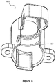
- Figure 4 shows the cover that cases the top surface of the housing according to an embodiment of the present invention.
- the cover (400) shown in figure 4 is used to provide a covering/casing to the top surface of the housing.
- the cover (400) is provided with a step (410) on its inner surface.
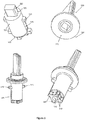
- Figure 5 shows the rotor-knob assembly of the electronic lock unit according to the present invention.
- the rotor (500) comprises of a top end (505), a bottom end (510) and at least two sideward protruding arms (515) which are spaced apart.
- the top end (505) of the rotor (500) is provided with a protrusion (520) which is fixed inside a depression/cavity (525) provided in a bottom surface (530) of the knob (550).
- the knob (550) is rigidly fixed to the top end (505) of the rotor (500).
- the bottom end (510) of the rotor (500) is provided with a hole (535) at its center and at least two protruding legs (540) spaced apart in radial direction from the hole (535).
- the rotor (500) is provided with at least one groove (545) on its periphery.
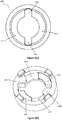
- Figures 6a and 6b shows the top surface and bottom surface of the ring of the electronic lock unit according to an embodiment of the present invention respectively.
- the ring (600) is provided with at least two plates (610) protruding from inner circumference of the ring (600), the plates (610) being spaced apart so as to form a slot (620) between any two adjacent plates (610).
- each plate (610) is provided with projections (630) to engage the arms (515) of the rotor (500) within the said projections (630).
- the ring rests on the top surface (310) of the housing in such a manner that the ring is sandwiched between the top surface (310) of the housing and the step (410) on the inner surface of the cover (400).
- the ring (600) when sandwiched between the top surface (310) of the housing and the step (410) on the inner surface of the cover (400) allows the rotor (500) and its protruding arms (515) to pass through the opening (350) provided in the top surface (310) of the housing.
- the projections (630) define the movement i.e. rotation of the knob from: steering LOCK to ignition OFF, ignition OFF to ignition ON and vice versa.
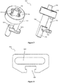
- Figure 7 shows the cam unit or cam assembly of the electronic lock unit according to an embodiment of the present invention.
- the cam unit (700) comprises of a cylindrical body (710) and a cam element (720) rigidly connected to the cylindrical body (710).
- the cylindrical body (710) is also termed as cam cavity and makes contact with the rotor (500).
- the cylindrical body (710) is provided with a vertical pillar (730) protruding from its center and at least two slots (740) in the radial direction from the vertical pillar (730).
- the said vertical pillar (730) is provided with a spring means located on its top surface.
- the vertical pillar (730) mates with the central hole (535) of the rotor (500) and the at least two slots (740) mate with the at least two legs (540) of the rotor (500).
- the cam element (720) is constituted of a first pillar (750) rigidly fixed to the bottom of the cylindrical body (710) and L shaped member connected to the first pillar (750).
- the first pillar (750) is offset from the center of the cylindrical body (710).
- the L shaped member is divided into a horizontal portion (760) and a vertical portion (770). As shown in figure 7 , the first pillar (750) divides the horizontal potion (760) into substantially two equal sections (760a, 760b).
- Figure 8 shows the cam follower of the electronic lock unit according to an embodiment of the present invention.
- the cam follower (800) comprises of a channel (810) and a T shaped groove (820) located at its circumference.
- the channel (810) accommodates the cam element (720) and allows rotation of the first pillar (750) of the cam element (720).
- the T shaped groove (820) accommodates one end of the locking bar/member (255) such that the locking member (255) moves with the movement of the cam follower (800).
- the said arrangement converts rotation of the cam element (720) into linear to and fro motion of the locking bar/member (255) for engaging/disengaging with the steering of the vehicle.
- the opening (350) in the top surface (310) of the housing (300) is provided with at least one spring loaded ball (275) which engages with the at least one groove (545) provided on the periphery of the rotor (500).
- the said arrangement enables the user to correctly identify the steering LOCK position i.e. the position where the user has to press the knob (550).
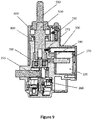
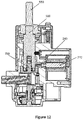
- FIGS 9-12 illustrate the cross sectional views of the electronic lock unit according to an embodiment of the present invention.
- the lock unit of the present invention works in conjunction with the electronic control unit (150, 265) which receives signals from an electronic key or FOB key for facilitating steering LOCK/UNLOCK and ignition ON/OFF of the vehicle.
- the key may be a battery operated key and is held by the user of the vehicle.
- the present invention implies that the users need not insert the key in the lock for steering LOCK/UNLOCK and engine ON/OFF of the vehicle.
- the lock unit of the present invention allows multilevel authentication process/methodology to run which permit steering UNLOCK and engine ON of the vehicle.
- the first level of authentication allows steering UNLOCK of the vehicle and the second level of authentication allows ignition ON of the vehicle.
- the user having the electronic key or FOB key must remain in a predetermined distance of the vehicle for the authentication process to complete successfully.
- the electronic key or FOB key is pre-programmed with specific ID codes which are transmitted continuously.
- the electronic control unit (150, 265) is in sleep mode (for instance when the vehicle is not in use) and is not able to detect the ID codes transmitted by the electronic key.
- the electronic control unit (150, 265) comes in active mode when a trigger signal is provided to the same.
- the trigger signal is provided by the first switch (230).
- the first switch (230) is provided either on the lock unit or at any place on the steering of the vehicle.
- the first switch (230) is actuated by the user of the vehicle.
- the actuation of the first switch (230) provides a trigger signal to the electronic control unit (150, 265) and initiates the multilevel authentication.
- the electronic control unit (150, 265) comes in active mode when a trigger signal is provided to it.
- the electronic control unit (150, 265) After the electronic control unit (150, 265) is in active mode, it receives ID codes transmitted by the electronic key and compares the received ID codes with ID coded stored in it. If the ID codes received by the electronic control unit (150, 265) matches with the ID codes previously stored in it, first level of authentication is said to be complete.
- the electronic control unit (150, 265) provides an electric pulse to the actuator unit (235).
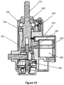
- the plunger (270) of the actuator unit (235) is pulled back. More specifically, the movable stopper (240) provided between the bottom surface of the rotor (500) and the cylindrical body (710) is pulled backward for allowing the rotor (500) to engage with the cam unit (700), as shown in figures 10 and 12 .
- the movable stopper (240) prohibiting the engagement between the rotor (500) and the cam unit (700) as shown in figure 9 is pulled backward for allowing the rotor (500) to engage with the cam unit (700).
- the user is able to push the knob (550). More specifically, the user is able to push the knob-rotor assembly.
- the knob-rotor assembly is pushed if the arms (515) of the rotor match with the slots (620) of the ring (600) thereby allowing the rotor (500) to pass through the opening (350) in the top surface (310) of the housing (300).
- the pushing of the knob (550) establishes the engagement between the rotor (500) and the cam unit (700) as shown in figures 10 and 12 .
- the central hole (535) of the rotor (500) mates with the vertical pillar (730) of the cylindrical body (710) thereby energizing the spring means and the at least two legs (540) of the rotor (500) mate with the at least two slots (740) provided in the cylindrical body (710).
- the user After, engagement of the rotor (500) with the cam unit (700), the user is able to rotate the knob (550) from steering LOCK to engine OFF position.
- the rotation of the knob (550) from steering LOCK to engine OFF is defined by the projections (630) of the ring (600).
- the rotation of the knob (550) from steering LOCK to engine OFF position causes rotation of the cam element (720) due to the engagement of the rotor (500) with the cam unit (700).
- the cam follower (800) accommodates the cam element (720) which is divided into first pillar (750) and L shaped member.
- the first pillar (750) being offset from the center of the cylindrical body (710) converts the rotation of the cam unit (700) into linear to and fro motion of the cam follower (800).
- the cam follower (800) is engaged with the locking bar/member (255).
- rotation of cam unit (700) in response to rotation of the knob (550) from steering LOCK to engine OFF) causes linear motion of the locking bar/member (255) for releasing the steering of the vehicle.
- the locking bar/member (255) holds the steering in the LOCK position.
- the locking bar (255) is moved inwards in response to the rotation of the knob (550) from steering LOCK to engine OFF, thereby unlocking or releasing the steering to move freely.
- the vehicle is now in engine OFF position.
- the user can further rotate the knob (550) to start the vehicle, i.e. the user can rotate the knob (550) from engine OFF to engine ON position.
- the rotation of the knob (550) from engine OFF to engine ON position is defined by the projections (630) of the ring (600).
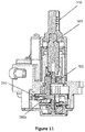
- the horizontal portion (760) of the cam element (720) actuates the second micro switch (260). More specifically, one of the sections of the horizontal portion (760) of the cam element (720) actuates the second micro switch (260). With reference to figures 6 and 11 , section (760b) actuates the second micro switch (260).
- the actuation of the second micro switch (260) sends a trigger signal to the electronic control unit (150, 265) which initiates the second level of authentication.
- the electronic control unit (150, 265) again receives ID codes transmitted by the electronic key and compares the received ID codes with ID coded stored in it. If the ID codes received by the electronic control unit (150, 265) matches with the ID codes previously stored in it, second level of authentication is said to be complete. If the second level of authentication is complete or successful, the engine of the vehicle will start. If the second level of authentication fails the engine will not start.
- the knob (550) is an integrated part of the lock unit which is free to rotate with the rotor (500) when an unauthorized user attempts to access the vehicle. The rotation is transferred to the cam unit (700) only in a condition when the authorized users operate the lock i.e. when the authentication process is completed. In this way, unauthorized users can only rotate the knob (550) but cannot operate the lock unit at steering LOCK position.
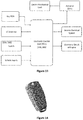
- Figure 14 shows the electronic key.
- the electronic key may be provided with a spare key to operate other accessories in the vehicle (i.e. seat lock, tool box lock, etc.)
- Figure 13 shows the block diagram of the electronic system of the lock unit according to an embodiment of the present invention.
- the electronic control unit (150, 265) receives ID codes from the FOB key for establishing the authentication process.
- the LF antenna which receives the ID codes may be an integral part of the electronic control unit (150, 265). In another embodiment, the LF antenna may be external to the electronic control unit (150, 265).
- the electronic control unit (150, 265) receives the trigger signals from the switches for initiating the multilevel authentication process. Furthermore, the electronic control unit (150, 265) receives input signals from other units of the vehicle.
- the electronic control unit (150, 265) provides an output in the form of electrical pulses to the actuator unit (235) for retracting the stopper (240). Moreover, the electronic control unit (150, 265) provides output signals to the vehicle electrical system and electronic circuit of the engine.
Landscapes
- Engineering & Computer Science (AREA)
- Mechanical Engineering (AREA)
- Lock And Its Accessories (AREA)
Claims (10)
- Unité de verrouillage électronique (100, 200) pour un véhicule comprenant une authentification multiniveau, ladite unité de verrouillage électronique (100, 200) comprenant:une unité de commande électronique (150, 265) ;un premier commutateur (140, 230) couplé de manière fonctionnelle à l'unité de commande électronique (150) pour déclencher un premier niveau d'authentification ;un rotor (215, 500) ayant une extrémité supérieure (505), une extrémité inférieure (510) et au moins deux bras saillants vers le côté (515) qui sont espacés ;un bouton (130, 220, 550) fixé de manière rigide à l'extrémité supérieure (505) du rotor (215, 500) pour faciliter le VERROUILLAGE/DÉVERROUILLAGE de la serrure de blocage et L'ACTIVATION/LA DÉSACTIVATION de l'allumage du véhicule ;une bague (225, 600) ayant au moins deux plaques (610) faisant saillie depuis la circonférence interne de la bague (225, 600), les plaques (610) étant espacées de sorte à former une fente (620) entre deux plaques quelconques adjacentes (610) pour permettre au rotor (215, 500) et à ses bras saillants (515) de passer à travers cette dernière ;la face inférieure de chaque plaque (610) comportant des saillies (630) pour venir en prise avec les bras (515) du rotor (215, 500) dans lesdites saillies (630) ;une unité de came (245, 700) comprenant :un corps cylindrique (710) qui s'accouple avec l'extrémité inférieure (510) du rotor (215, 500) ; etun élément de came (720) raccordé de manière rigide au corps cylindrique (710) ;une butée mobile (240) positionnée entre l'extrémité inférieure (510) du rotor (215, 500) et le corps cylindrique (710) pour séparer le rotor (215, 500) de l'unité de came (245, 700) ; etun second commutateur (260) couplé de manière fonctionnelle à l'unité de commande électronique (150, 265) et qui est actionné par le mouvement de l'élément de came (720) pour déclencher un second niveau d'authentification ; dans laquelle le premier commutateur (140, 230) est actionné par un utilisateur, le premier niveau d'authentification permettant un DÉVERROUILLAGE de la serrure de blocage du véhicule, le second niveau d'authentification permettant une ACTIVATION de l'allumage du véhicule, dans laquelle :
l'unité de commande électronique (150, 265) est configurée :pour recevoir des codes d'identification (ID) transmis par une clé électronique ; etpour comparer les codes d'identification reçus avec des codes d'identification stockés en son sein,dans laquelle le premier niveau d'authentification est dit être achevé si les codes d'identification reçus par l'unité de commande électronique (150, 265) corresponde aux les codes d'identification stockés en son sein ;dans laquelle l'élément de came (720) comprend :un premier pilier (750) fixé de manière rigide à la partie inférieure du corps cylindrique et qui est décalé par rapport à son centre ; etun élément en forme de L ayant une partie horizontale (760) et une partie verticale, dans laquelle le premier pilier (750) étant fixé de manière rigide sur la partie horizontale (760) de telle sorte que la partie horizontale (760) soit sensiblement divisée en deux sections égales (760a, 760b) ;dans laquelle l'une des sections (760a, 760b) de la partie horizontale (760) de l'élément en forme de L actionne le second commutateur (260) et dans laquelle le second niveau d'authentification comprend :
l'unité de verrouillage électronique (150, 265) qui est configurée :pour recevoir des codes d'identification transmis par la clé électronique ; etpour comparer les codes d'identification reçus avec des codes d'identification stockés en son sein,
dans laquelle le second niveau d'authentification est dit être achevé si les codes d'identification reçus par l'unité de commande électronique (150, 265) correspond aux codes d'identification stockés en son sein. - Unité de verrouillage électronique selon la revendication 1, dans laquelle :l'extrémité supérieure du rotor (215, 500) comporte une saillie (520) ;l'extrémité inférieure du rotor comporte un trou (535) en son centre et au moins deux pattes saillantes (540) espacées dans une direction radiale depuis le trou (535) ; etle bouton (550) comporte un fond circulaire ayant un creux pour loger la saillie (520) du rotor (215, 500).
- Unité de verrouillage électronique selon les revendications 1 et 2, dans laquelle :
le corps cylindrique (710) comporte un pilier vertical (730) faisant saillie depuis son centre pour s'accoupler avec le trou central (535) du rotor (215, 500) et au moins deux fentes (620) pour loger les deux, ou plus, pattes (540) du rotor (215, 500). - Unité de verrouillage électronique selon la revendication 1, comprenant en outre :
un boîtier (110, 205, 300) ayant une surface supérieure (310), une surface inférieure (320), une chambre (330) sur un côté et un trou (340) sur un autre côté, dans laquelle les surfaces supérieure et inférieure (310, 320) sont pourvues d'ouvertures (350). - Unité de verrouillage électronique selon la revendication 4, comprenant en outre :
une unité d'actionnement (235) située dans la chambre (330), ladite unité d'actionnement (235) comprenant :
un piston plongeur raccordé à la butée mobile (240) pour permettre un mouvement de poussée-traction de la butée (240). - Unité de verrouillage électronique selon les revendications 1 et 4, dans laquelle la bague (225, 600) repose sur la surface supérieure (310) du boîtier (110, 205, 300) et le rotor (215, 500) est englobé dans l'ouverture (350) dans la surface supérieure (310).
- Unité de verrouillage électronique selon la revendication 6, comprenant en outre :un couvercle (210) pour couvrir la surface supérieure (310) du boîtier (110, 205, 300), ledit couvercle (210) étant pourvu d'une surépaisseur (410) sur sa surface interne,dans laquelle la bague (225, 600) est prise en sandwich entre la surface supérieure (310) du boîtier et la surépaisseur (410) sur la surface interne du couvercle (210).
- Unité de verrouillage électronique selon la revendication 1, comprenant en outre :un galet de came (250, 800) ayant un canal (810) pour loger l'élément de came (720) et une rainure en forme de T (820) située sur sa circonférence, ledit élément de came (720) déplaçant le galet de came (250, 800) d'avant en arrière à la suite de la rotation du bouton (130, 550) ; etun élément de verrouillage (255) ayant une extrémité raccordée à la rainure en forme de T (820) pour effectuer un mouvement d'avant en arrière pour venir en prise avec la serrure de blocage/pour se désolidariser de cette dernière.
- Unité de verrouillage électronique selon la revendication 4, dans laquelle le second commutateur (260) est placé dans l'un des coins (370) de la surface inférieure (320) du boîtier (110, 205, 300).
- Unité de verrouillage électronique selon la revendication 4, dans laquelle l'ouverture (350) dans la surface supérieure (310) comprend au moins une bille chargée sous l'action d'un ressort (275) pour venir en prise avec au moins une rainure (545) ménagée sur la périphérie du rotor (215, 500).
Applications Claiming Priority (2)
| Application Number | Priority Date | Filing Date | Title |
|---|---|---|---|
| IN3655DE2013 | 2013-12-19 | ||
| PCT/IB2014/067115 WO2015092754A1 (fr) | 2013-12-19 | 2014-12-19 | Commutateur d'allumage perfectionné comportant une serrure de blocage |
Publications (3)
| Publication Number | Publication Date |
|---|---|
| EP3083339A1 EP3083339A1 (fr) | 2016-10-26 |
| EP3083339A4 EP3083339A4 (fr) | 2017-05-17 |
| EP3083339B1 true EP3083339B1 (fr) | 2019-10-16 |
Family
ID=53402207
Family Applications (1)
| Application Number | Title | Priority Date | Filing Date |
|---|---|---|---|
| EP14871760.6A Not-in-force EP3083339B1 (fr) | 2013-12-19 | 2014-12-19 | Serrure electronique pour une voiture |
Country Status (3)
| Country | Link |
|---|---|
| EP (1) | EP3083339B1 (fr) |
| JP (1) | JP6276421B2 (fr) |
| WO (1) | WO2015092754A1 (fr) |
Families Citing this family (5)
| Publication number | Priority date | Publication date | Assignee | Title |
|---|---|---|---|---|
| WO2018179008A1 (fr) * | 2017-03-29 | 2018-10-04 | Minda Corporation Limited | Dispositif de verrouillage de cylindre intelligent |
| CN107575099B (zh) * | 2017-09-29 | 2023-04-25 | 锐库(上海)机电科技有限公司 | 用于二轮车的电子锁系统和二轮车及其解锁控制方法 |
| EP3707034B1 (fr) * | 2017-11-07 | 2026-03-11 | Minda Corporation Limited | Verrou d'allumage intelligent multifonction pour véhicules |
| CN108898705A (zh) * | 2018-06-14 | 2018-11-27 | 贵州大学 | 一种具有权限分享的家庭门禁系统及其授权方法 |
| CN112448816B (zh) * | 2019-08-31 | 2021-10-19 | 华为技术有限公司 | 一种身份验证方法及装置 |
Family Cites Families (7)
| Publication number | Priority date | Publication date | Assignee | Title |
|---|---|---|---|---|
| JPS5436424Y2 (fr) * | 1976-03-27 | 1979-11-02 | ||
| JPS62231853A (ja) * | 1986-04-02 | 1987-10-12 | Nissan Motor Co Ltd | ステアリングロツク装置 |
| DE4240283C1 (de) * | 1992-12-01 | 1993-11-25 | Daimler Benz Ag | Lenkschloß für Kraftfahrzeuge |
| KR20030096944A (ko) | 2002-06-18 | 2003-12-31 | 현대자동차주식회사 | 차량의 도난 방지 시스템 |
| JP4405903B2 (ja) * | 2004-12-24 | 2010-01-27 | 株式会社アルファ | ステアリングロック装置 |
| JP4572729B2 (ja) * | 2005-04-20 | 2010-11-04 | マツダ株式会社 | 車両用アイドルストップスタート制御装置 |
| JP4767593B2 (ja) * | 2005-06-02 | 2011-09-07 | 株式会社ホンダロック | 車両用イグニッションスイッチの操作装置 |
-
2014
- 2014-12-19 WO PCT/IB2014/067115 patent/WO2015092754A1/fr not_active Ceased
- 2014-12-19 EP EP14871760.6A patent/EP3083339B1/fr not_active Not-in-force
- 2014-12-19 JP JP2016559688A patent/JP6276421B2/ja not_active Expired - Fee Related
Non-Patent Citations (1)
| Title |
|---|
| None * |
Also Published As
| Publication number | Publication date |
|---|---|
| JP2017509535A (ja) | 2017-04-06 |
| WO2015092754A1 (fr) | 2015-06-25 |
| JP6276421B2 (ja) | 2018-02-07 |
| EP3083339A1 (fr) | 2016-10-26 |
| EP3083339A4 (fr) | 2017-05-17 |
Similar Documents
| Publication | Publication Date | Title |
|---|---|---|
| EP3083339B1 (fr) | Serrure electronique pour une voiture | |
| CN105604413B (zh) | 具有可取下的盖的门把手 | |
| KR101840259B1 (ko) | 차량 순정리모콘을 이용한 원격도어시스템 및 원격도어제어방법 | |
| US11447976B2 (en) | Two-wheeler lock having an alarm function | |
| KR0157244B1 (ko) | 원격 제어식 도난 방지 장치 | |
| US8770453B2 (en) | Power lock assembly for vehicle roof rack | |
| US20080245119A1 (en) | Cylinder lock device | |
| US4425770A (en) | Steering lock assembly | |
| US20030079509A1 (en) | Steering lock apparatus | |
| CN111094676A (zh) | 机电锁芯 | |
| US20220145670A1 (en) | Lock assembly for a bicycle | |
| US10319163B2 (en) | Remote control unlocking and locking system | |
| KR20110096955A (ko) | 레버 일체형 디지로그 도어락 | |
| US20090206990A1 (en) | Aftermarket convenience entry and start system | |
| US20200122682A1 (en) | Locking device, in particular, for a motor vehicle | |
| JP6437888B2 (ja) | Obdポートのロック装置 | |
| CN109891039B (zh) | 机动车用锁闭单元 | |
| US20160207498A1 (en) | Anti-theft device for a steering column of a motor vehicle | |
| WO2016103210A1 (fr) | Mécanisme de verrouillage de couvercle de réservoir de carburant sans clé | |
| EP3707034B1 (fr) | Verrou d'allumage intelligent multifonction pour véhicules | |
| JP7272581B2 (ja) | ステアリングロック装置 | |
| JP4733455B2 (ja) | ステアリングロック装置 | |
| KR100818223B1 (ko) | 전자인증시스템과 연동되는 스티어링 로크장치 및 그 제작방법 | |
| CN120660124A (zh) | 带有具有绝缘区的钥匙的电气多触点系统 | |
| KR0150169B1 (ko) | 차량용 키의 도난 방지구조 |
Legal Events
| Date | Code | Title | Description |
|---|---|---|---|
| PUAI | Public reference made under article 153(3) epc to a published international application that has entered the european phase |
Free format text: ORIGINAL CODE: 0009012 |
|
| 17P | Request for examination filed |
Effective date: 20160620 |
|
| AK | Designated contracting states |
Kind code of ref document: A1 Designated state(s): AL AT BE BG CH CY CZ DE DK EE ES FI FR GB GR HR HU IE IS IT LI LT LU LV MC MK MT NL NO PL PT RO RS SE SI SK SM TR |
|
| AX | Request for extension of the european patent |
Extension state: BA ME |
|
| DAX | Request for extension of the european patent (deleted) | ||
| A4 | Supplementary search report drawn up and despatched |
Effective date: 20170421 |
|
| RIC1 | Information provided on ipc code assigned before grant |
Ipc: B60R 25/021 20130101AFI20170413BHEP |
|
| GRAP | Despatch of communication of intention to grant a patent |
Free format text: ORIGINAL CODE: EPIDOSNIGR1 |
|
| STAA | Information on the status of an ep patent application or granted ep patent |
Free format text: STATUS: GRANT OF PATENT IS INTENDED |
|
| INTG | Intention to grant announced |
Effective date: 20190424 |
|
| GRAS | Grant fee paid |
Free format text: ORIGINAL CODE: EPIDOSNIGR3 |
|
| GRAA | (expected) grant |
Free format text: ORIGINAL CODE: 0009210 |
|
| STAA | Information on the status of an ep patent application or granted ep patent |
Free format text: STATUS: THE PATENT HAS BEEN GRANTED |
|
| AK | Designated contracting states |
Kind code of ref document: B1 Designated state(s): AL AT BE BG CH CY CZ DE DK EE ES FI FR GB GR HR HU IE IS IT LI LT LU LV MC MK MT NL NO PL PT RO RS SE SI SK SM TR |
|
| REG | Reference to a national code |
Ref country code: GB Ref legal event code: FG4D |
|
| REG | Reference to a national code |
Ref country code: CH Ref legal event code: EP |
|
| REG | Reference to a national code |
Ref country code: DE Ref legal event code: R096 Ref document number: 602014055406 Country of ref document: DE |
|
| REG | Reference to a national code |
Ref country code: IE Ref legal event code: FG4D |
|
| REG | Reference to a national code |
Ref country code: AT Ref legal event code: REF Ref document number: 1190967 Country of ref document: AT Kind code of ref document: T Effective date: 20191115 |
|
| REG | Reference to a national code |
Ref country code: NL Ref legal event code: MP Effective date: 20191016 |
|
| REG | Reference to a national code |
Ref country code: LT Ref legal event code: MG4D |
|
| REG | Reference to a national code |
Ref country code: AT Ref legal event code: MK05 Ref document number: 1190967 Country of ref document: AT Kind code of ref document: T Effective date: 20191016 |
|
| PG25 | Lapsed in a contracting state [announced via postgrant information from national office to epo] |
Ref country code: NL Free format text: LAPSE BECAUSE OF FAILURE TO SUBMIT A TRANSLATION OF THE DESCRIPTION OR TO PAY THE FEE WITHIN THE PRESCRIBED TIME-LIMIT Effective date: 20191016 Ref country code: PL Free format text: LAPSE BECAUSE OF FAILURE TO SUBMIT A TRANSLATION OF THE DESCRIPTION OR TO PAY THE FEE WITHIN THE PRESCRIBED TIME-LIMIT Effective date: 20191016 Ref country code: GR Free format text: LAPSE BECAUSE OF FAILURE TO SUBMIT A TRANSLATION OF THE DESCRIPTION OR TO PAY THE FEE WITHIN THE PRESCRIBED TIME-LIMIT Effective date: 20200117 Ref country code: LT Free format text: LAPSE BECAUSE OF FAILURE TO SUBMIT A TRANSLATION OF THE DESCRIPTION OR TO PAY THE FEE WITHIN THE PRESCRIBED TIME-LIMIT Effective date: 20191016 Ref country code: AT Free format text: LAPSE BECAUSE OF FAILURE TO SUBMIT A TRANSLATION OF THE DESCRIPTION OR TO PAY THE FEE WITHIN THE PRESCRIBED TIME-LIMIT Effective date: 20191016 Ref country code: PT Free format text: LAPSE BECAUSE OF FAILURE TO SUBMIT A TRANSLATION OF THE DESCRIPTION OR TO PAY THE FEE WITHIN THE PRESCRIBED TIME-LIMIT Effective date: 20200217 Ref country code: FI Free format text: LAPSE BECAUSE OF FAILURE TO SUBMIT A TRANSLATION OF THE DESCRIPTION OR TO PAY THE FEE WITHIN THE PRESCRIBED TIME-LIMIT Effective date: 20191016 Ref country code: BG Free format text: LAPSE BECAUSE OF FAILURE TO SUBMIT A TRANSLATION OF THE DESCRIPTION OR TO PAY THE FEE WITHIN THE PRESCRIBED TIME-LIMIT Effective date: 20200116 Ref country code: SE Free format text: LAPSE BECAUSE OF FAILURE TO SUBMIT A TRANSLATION OF THE DESCRIPTION OR TO PAY THE FEE WITHIN THE PRESCRIBED TIME-LIMIT Effective date: 20191016 Ref country code: LV Free format text: LAPSE BECAUSE OF FAILURE TO SUBMIT A TRANSLATION OF THE DESCRIPTION OR TO PAY THE FEE WITHIN THE PRESCRIBED TIME-LIMIT Effective date: 20191016 Ref country code: NO Free format text: LAPSE BECAUSE OF FAILURE TO SUBMIT A TRANSLATION OF THE DESCRIPTION OR TO PAY THE FEE WITHIN THE PRESCRIBED TIME-LIMIT Effective date: 20200116 |
|
| PGFP | Annual fee paid to national office [announced via postgrant information from national office to epo] |
Ref country code: GB Payment date: 20191220 Year of fee payment: 6 |
|
| PG25 | Lapsed in a contracting state [announced via postgrant information from national office to epo] |
Ref country code: IS Free format text: LAPSE BECAUSE OF FAILURE TO SUBMIT A TRANSLATION OF THE DESCRIPTION OR TO PAY THE FEE WITHIN THE PRESCRIBED TIME-LIMIT Effective date: 20200224 Ref country code: HR Free format text: LAPSE BECAUSE OF FAILURE TO SUBMIT A TRANSLATION OF THE DESCRIPTION OR TO PAY THE FEE WITHIN THE PRESCRIBED TIME-LIMIT Effective date: 20191016 Ref country code: RS Free format text: LAPSE BECAUSE OF FAILURE TO SUBMIT A TRANSLATION OF THE DESCRIPTION OR TO PAY THE FEE WITHIN THE PRESCRIBED TIME-LIMIT Effective date: 20191016 |
|
| PG25 | Lapsed in a contracting state [announced via postgrant information from national office to epo] |
Ref country code: AL Free format text: LAPSE BECAUSE OF FAILURE TO SUBMIT A TRANSLATION OF THE DESCRIPTION OR TO PAY THE FEE WITHIN THE PRESCRIBED TIME-LIMIT Effective date: 20191016 |
|
| REG | Reference to a national code |
Ref country code: DE Ref legal event code: R097 Ref document number: 602014055406 Country of ref document: DE |
|
| PG2D | Information on lapse in contracting state deleted |
Ref country code: IS |
|
| PG25 | Lapsed in a contracting state [announced via postgrant information from national office to epo] |
Ref country code: CZ Free format text: LAPSE BECAUSE OF FAILURE TO SUBMIT A TRANSLATION OF THE DESCRIPTION OR TO PAY THE FEE WITHIN THE PRESCRIBED TIME-LIMIT Effective date: 20191016 Ref country code: RO Free format text: LAPSE BECAUSE OF FAILURE TO SUBMIT A TRANSLATION OF THE DESCRIPTION OR TO PAY THE FEE WITHIN THE PRESCRIBED TIME-LIMIT Effective date: 20191016 Ref country code: ES Free format text: LAPSE BECAUSE OF FAILURE TO SUBMIT A TRANSLATION OF THE DESCRIPTION OR TO PAY THE FEE WITHIN THE PRESCRIBED TIME-LIMIT Effective date: 20191016 Ref country code: EE Free format text: LAPSE BECAUSE OF FAILURE TO SUBMIT A TRANSLATION OF THE DESCRIPTION OR TO PAY THE FEE WITHIN THE PRESCRIBED TIME-LIMIT Effective date: 20191016 Ref country code: DK Free format text: LAPSE BECAUSE OF FAILURE TO SUBMIT A TRANSLATION OF THE DESCRIPTION OR TO PAY THE FEE WITHIN THE PRESCRIBED TIME-LIMIT Effective date: 20191016 Ref country code: IS Free format text: LAPSE BECAUSE OF FAILURE TO SUBMIT A TRANSLATION OF THE DESCRIPTION OR TO PAY THE FEE WITHIN THE PRESCRIBED TIME-LIMIT Effective date: 20200216 |
|
| REG | Reference to a national code |
Ref country code: CH Ref legal event code: PL |
|
| PLBE | No opposition filed within time limit |
Free format text: ORIGINAL CODE: 0009261 |
|
| STAA | Information on the status of an ep patent application or granted ep patent |
Free format text: STATUS: NO OPPOSITION FILED WITHIN TIME LIMIT |
|
| REG | Reference to a national code |
Ref country code: BE Ref legal event code: MM Effective date: 20191231 |
|
| PG25 | Lapsed in a contracting state [announced via postgrant information from national office to epo] |
Ref country code: SK Free format text: LAPSE BECAUSE OF FAILURE TO SUBMIT A TRANSLATION OF THE DESCRIPTION OR TO PAY THE FEE WITHIN THE PRESCRIBED TIME-LIMIT Effective date: 20191016 Ref country code: MC Free format text: LAPSE BECAUSE OF FAILURE TO SUBMIT A TRANSLATION OF THE DESCRIPTION OR TO PAY THE FEE WITHIN THE PRESCRIBED TIME-LIMIT Effective date: 20191016 Ref country code: SM Free format text: LAPSE BECAUSE OF FAILURE TO SUBMIT A TRANSLATION OF THE DESCRIPTION OR TO PAY THE FEE WITHIN THE PRESCRIBED TIME-LIMIT Effective date: 20191016 |
|
| 26N | No opposition filed |
Effective date: 20200717 |
|
| PG25 | Lapsed in a contracting state [announced via postgrant information from national office to epo] |
Ref country code: LU Free format text: LAPSE BECAUSE OF NON-PAYMENT OF DUE FEES Effective date: 20191219 Ref country code: FR Free format text: LAPSE BECAUSE OF NON-PAYMENT OF DUE FEES Effective date: 20191231 Ref country code: IE Free format text: LAPSE BECAUSE OF NON-PAYMENT OF DUE FEES Effective date: 20191219 |
|
| PG25 | Lapsed in a contracting state [announced via postgrant information from national office to epo] |
Ref country code: BE Free format text: LAPSE BECAUSE OF NON-PAYMENT OF DUE FEES Effective date: 20191231 Ref country code: SI Free format text: LAPSE BECAUSE OF FAILURE TO SUBMIT A TRANSLATION OF THE DESCRIPTION OR TO PAY THE FEE WITHIN THE PRESCRIBED TIME-LIMIT Effective date: 20191016 Ref country code: LI Free format text: LAPSE BECAUSE OF NON-PAYMENT OF DUE FEES Effective date: 20191231 Ref country code: CH Free format text: LAPSE BECAUSE OF NON-PAYMENT OF DUE FEES Effective date: 20191231 |
|
| PG25 | Lapsed in a contracting state [announced via postgrant information from national office to epo] |
Ref country code: CY Free format text: LAPSE BECAUSE OF FAILURE TO SUBMIT A TRANSLATION OF THE DESCRIPTION OR TO PAY THE FEE WITHIN THE PRESCRIBED TIME-LIMIT Effective date: 20191016 |
|
| PG25 | Lapsed in a contracting state [announced via postgrant information from national office to epo] |
Ref country code: HU Free format text: LAPSE BECAUSE OF FAILURE TO SUBMIT A TRANSLATION OF THE DESCRIPTION OR TO PAY THE FEE WITHIN THE PRESCRIBED TIME-LIMIT; INVALID AB INITIO Effective date: 20141219 Ref country code: MT Free format text: LAPSE BECAUSE OF FAILURE TO SUBMIT A TRANSLATION OF THE DESCRIPTION OR TO PAY THE FEE WITHIN THE PRESCRIBED TIME-LIMIT Effective date: 20191016 |
|
| PGFP | Annual fee paid to national office [announced via postgrant information from national office to epo] |
Ref country code: IT Payment date: 20210625 Year of fee payment: 7 Ref country code: DE Payment date: 20210624 Year of fee payment: 7 |
|
| GBPC | Gb: european patent ceased through non-payment of renewal fee |
Effective date: 20201219 |
|
| PG25 | Lapsed in a contracting state [announced via postgrant information from national office to epo] |
Ref country code: GB Free format text: LAPSE BECAUSE OF NON-PAYMENT OF DUE FEES Effective date: 20201219 |
|
| PG25 | Lapsed in a contracting state [announced via postgrant information from national office to epo] |
Ref country code: TR Free format text: LAPSE BECAUSE OF FAILURE TO SUBMIT A TRANSLATION OF THE DESCRIPTION OR TO PAY THE FEE WITHIN THE PRESCRIBED TIME-LIMIT Effective date: 20191016 |
|
| PG25 | Lapsed in a contracting state [announced via postgrant information from national office to epo] |
Ref country code: MK Free format text: LAPSE BECAUSE OF FAILURE TO SUBMIT A TRANSLATION OF THE DESCRIPTION OR TO PAY THE FEE WITHIN THE PRESCRIBED TIME-LIMIT Effective date: 20191016 |
|
| REG | Reference to a national code |
Ref country code: DE Ref legal event code: R119 Ref document number: 602014055406 Country of ref document: DE |
|
| PG25 | Lapsed in a contracting state [announced via postgrant information from national office to epo] |
Ref country code: DE Free format text: LAPSE BECAUSE OF NON-PAYMENT OF DUE FEES Effective date: 20220701 |
|
| PG25 | Lapsed in a contracting state [announced via postgrant information from national office to epo] |
Ref country code: IT Free format text: LAPSE BECAUSE OF NON-PAYMENT OF DUE FEES Effective date: 20211219 |