EP3083338B1 - Schalter für ein gurtschloss in staub- und/oder wassergeschützter ausführung - Google Patents
Schalter für ein gurtschloss in staub- und/oder wassergeschützter ausführung Download PDFInfo
- Publication number
- EP3083338B1 EP3083338B1 EP14828002.7A EP14828002A EP3083338B1 EP 3083338 B1 EP3083338 B1 EP 3083338B1 EP 14828002 A EP14828002 A EP 14828002A EP 3083338 B1 EP3083338 B1 EP 3083338B1
- Authority
- EP
- European Patent Office
- Prior art keywords
- switch
- contact
- housing
- actuating element
- spring
- Prior art date
- Legal status (The legal status is an assumption and is not a legal conclusion. Google has not performed a legal analysis and makes no representation as to the accuracy of the status listed.)
- Not-in-force
Links
Images


Classifications
-
- B—PERFORMING OPERATIONS; TRANSPORTING
- B60—VEHICLES IN GENERAL
- B60R—VEHICLES, VEHICLE FITTINGS, OR VEHICLE PARTS, NOT OTHERWISE PROVIDED FOR
- B60R22/00—Safety belts or body harnesses in vehicles
- B60R22/48—Control systems, alarms, or interlock systems, for the correct application of the belt or harness
- B60R2022/4808—Sensing means arrangements therefor
- B60R2022/4816—Sensing means arrangements therefor for sensing locking of buckle
Definitions
- the present invention relates to a switch in dust and / or water-resistant design, which is used in a buckle of restraint systems in motor vehicles for use and displays the functional locking of the inserted into the buckle tongue of the seat belt.
- a switch for a buckle of restraint systems of motor vehicles to indicate that the belt tongue is inserted into the buckle and properly locked, with two contact plates, wherein a contact plate is formed after its contact-making end as a double contact tongue and these are arranged within the buckle, said contact areas of the contact plates are provided in a protected from foreign material upper housing interior of the switch housing, the switch housing is disposed within the buckle and a contact plate is formed as a contact spring with a hammer-shaped area at the contact end and a central arcuate area and the arcuate portion of the contact spring in a laterally from the housing interior arranged channel protrudes and the contact by moving a slider in the channel is switchable.
- the contact force at the contact point according to the leverage ratios to the clamping point is low and the risk that when fully actuated the slide (due to its low height) an undesired switching back (closing) of the contact takes place (Overtravel- Effect).
- a signal unit for the seat belt of seat belts known. It consists of a printed circuit board, which is equipped with electronic components and resilient contact plates for a switch.
- the circuit board is mounted in a housing which is mounted on the outer surface of the buckle.
- a pivot lever is mounted on a pin which is rotated upon insertion of the belt tongue in the buckle by sliding an edge of the belt tongue on a sliding surface of the pivot lever against the action of a torsion spring in the contact space of the signal unit and switches the contacts.
- Japanese Utility Model Application Sho-61-200834 discloses a buckle having a seat belt-on-the-seat signaling unit.
- the buckle consists of two halves and a circuit board.
- a contact is formed as an arcuate portion of the conductor.
- a contact contact spring in the space between the housing part and the board, which is arc-shaped at its lower end.
- the switching elements are disposed within the buckle housing, but not in a separate switch housing. Penetrating debris or liquids (through the opening of the buckle) can directly reach the contact elements and thus lead to functional failures.
- the US 4,163,128 describes a safety buckle with a switch, which consists of two resilient contact plates, the ends of which touch when not inserted belt tongue.
- the switching takes place by two cam tracks, which are located on a mounted on a pin of the buckle housing rotary actuator.
- the rotary actuator is rotated by the belt tongue in their insertion into the buckle against the action of a torsion spring so that the cam tracks deflect the ends of the contact plates in succession and thereby open the contact.
- the rotation takes place via a pin which is perpendicular to the rotary actuator and which engages with the belt tongue.
- the downshift takes place by automatic return of the rotary actuator due to the action of the torsion spring and springback of the contact plates after pulling the belt tongue.
- the contact plates are integrated into the buckle, but not in a separate switch housing.
- the insertion longitudinal movement of the belt tongue can not be used directly here.
- the US 5,590,904 A describes a buckle with a switching element for detecting the proper locking of the tongue in the buckle.
- the switching element consists of an open frame, on which the switching contacts are arranged.
- the contact elements are slightly arcuate in the upper region and abut each other.
- the switching contacts are open inside the buckle housing or liquids can reach the switch contacts directly, which functional failures can be caused.
- EP 1 485 276 B1 a switch for a buckle with two contact plates, wherein a first contact plate is formed after its contact-making end as a double contact tongue and a second contact plate as a contact spring with a hammer-shaped region at the contact-bearing end.
- the contact areas of both contact plates are in a largely protected from foreign substances upper housing interior of the switch housing.
- the contact spring includes an arcuate portion which projects through a corresponding opening in the switch housing in a laterally disposed from the housing interior channel, which is part of the switch. In this channel, a slider belonging to the belt buckle is moved into the belt buckle when inserting the belt tongue into the belt and hits the projecting into the channel arcuate portion of the contact spring.
- the contact spring is deflected against its clamping force in the direction of the housing interior and causes the electrical switching operation at the contact-making end of the contact spring together with the double contact tongue of the first contact plate.
- the switch can be designed as an opener or closer.
- the switch has a housing interior protected from foreign substances, in which the contact plates, consisting of a fixed contact plate and a contact spring plate, are arranged and switchable by means of an actuating strip formed from a rectangular sheet metal strip, wherein the operating handle with its angling the channel facing side of the housing interior penetrates and is pivotally mounted with its other end in the switch housing.
- the bend at the lower end has a semi-circular end portion which is pivotally mounted in a recess in the switch housing.
- the present invention has the object, in an to integrate its structure simple switch in the buckle, with the reliable state, whether a buckle of a seat belt of a vehicle is closed or opened, can be detected and which is inexpensive to produce, the switch contacts in a largely protected from penetrating dirt space within the Switch housing are arranged.
- the object is achieved in that the switch in dust and / or water-resistant design for a buckle of restraint systems of motor vehicles to indicate that the belt tongue is inserted into the buckle and properly locked outside the housing interior has a rotatably mounted actuating element, wherein the actuating element arcuate and is provided on its side opposite the storage side with a sliding portion and between the storage and the sliding portion with a lower side of the housing penetrating dome-shaped area.
- the dome-shaped region acts with its arcuate portion when deflecting the actuating element on the contact spring and thus closes the contact.
- the contact spring deflects the actuating element such that the stop collar rests on the inside of the lower side of the housing. against slipping and to limit the pivotal movement a stop collar is arranged on the dome-shaped area.
- a spring may additionally be provided.
- the spring deflects the actuator in such a way that the stop collar rests on the inside of the lower side of the housing.
- the switch can be designed both as a closer with resistance coding and as a closer without resistance coding. A version as an opener is possible.
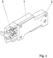
- FIG. 1 shows the switch according to the invention for installation in a housing of a buckle.
- This consists of the switch housing 1 with arranged therein contact elements (fixed contact 10 and contact spring 11 ), the actuating element 4, a printed circuit board 12 and a switch housing 1 occlusive housing cover 2.
- the connection area 3 serves the line connection of the switch.
- FIG. 2 shows a section through the switch according to the invention in the actuated state.
- the switch which is designed as a closer, consists of the switch housing 1 , which is closed by means of a housing cover 2 .
- the switch has a closed housing interior 9 , which receives the fixed contact 10 and the contact spring 11 and the circuit board 14 .
- a connection region 3 is provided, which with the fixed contact 10 and the contact spring 11 is connected. These can be connected to the connection lines here.
- the actuating element 4 is pivotally mounted on the one hand by means of a bearing 5 in the switch housing 1 .
- the dome-shaped portion 6 penetrates the lower side of the housing 13 and abuts with its arcuate portion on the contact spring 11 .
- the stop collar 8 on the dome-shaped region 6 prevents slipping out of the dome-shaped region 6 in the unactuated state. At the same time, the deflection of the actuating element 4 is limited.
- FIG. 3 shows a section through a further embodiment of the switch according to the invention.
- the switch has substantially the same structure as described in the previous example.
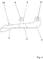
- the actuating element 4 ( Fig. 4 ) is arcuate and has on one side a bearing eye 16 . On the opposite side of the sliding portion 7 is provided which causes the deflection of the actuating element 4 and thus the contacting of fixed contact 10 and spring contact 11 in conjunction with the slider present in the buckle when inserting the belt tongue.
- a spring receptacle 14 for receiving the spring 15 is provided on the side opposite the sliding region 7 .
- the spring 15 which is supported against the lower side of the housing 13 , presses the actuating element 4 in the direction of the sliding surface of the slider, wherein the stop collar 8 bears against the inside of the lower housing side 13 .
- the deflection movement of the actuating element 4 is limited in the unactuated state.
- the spring 15 under dynamic loads (vibrations, shock) permanent holding the switch in the unactuated state, without causing misinterpretation about the switching state.
- the thus formed switch can be fully automatically mounted.
- fixed contact 10, contact spring 11 and the actuator 4 can be used.
- the switch After closing the switch housing 1 by means of the housing cover 2 , the switch can be checked for its function. Then then the leads can be attached. This is largely automated by crimping or welding, since the housing 1 in the connection area 3 is open.
- the housing interior 9 is closed except for the gap surrounding the dome-shaped region 6 of the actuating element 4 , so that the penetration of foreign bodies, such as dust and water in the contact area is largely prevented. Thus, a protection against functional failures is ensured by pollution.
Landscapes
- Engineering & Computer Science (AREA)
- Automation & Control Theory (AREA)
- Mechanical Engineering (AREA)
- Buckles (AREA)
- Automotive Seat Belt Assembly (AREA)
- Slide Switches (AREA)
Description
- Die vorliegende Erfindung betrifft einen Schalter in staub- und/oder wassergeschützter Ausführung , der in einem Gurtschloß von Rückhaltesystemen in Kraftfahrzeugen zur Anwendung kommt und die funktionsgemäße Verriegelung der in das Gurtschloß eingesteckten Zunge des Sicherheitsgurtes anzeigt.
- Bekannt ist aus der
DE 43 38 485 A1 ein für die fail-safe-Abfrage eingerichteter Sicherheitsgurtverschluß mit Mikroschalter, wobei der Mikroschalter mit zwei am Verriegelungsvorgang des Verschlusses unabhängig voneinander beteiligten Funktionsteilen derart gekoppelt ist, daß der Mikroschalter nur bei den beiden gleichzeitig in der Verriegelungsposition stehenden Funktionsstellen des Verschlusses seine geschlossene und für die Auslösung weiterer Funktionselemente der Sicherheitseinrichtung eingerichtete Stellung einnimmt. - Bekannt ist aus dem
DE 202 04 318 U1 ein Schalter für ein Gurtschloß von Rückhaltesystemen von Kraftfahrzeugen zur Anzeige, daß die Gurtzunge in das Gurtschloß eingesteckt und ordnungsgemäß verriegelt ist, mit zwei Kontaktblechen, wobei ein Kontaktblech nach seinem kontaktgebenden Ende hin als Doppelkontaktzunge ausgebildet ist und diese innerhalb des Gurtschlosses angeordnet sind, wobei die kontaktgebenden Bereiche der Kontaktbleche in einem vor Fremdstoffen geschützten oberen Gehäuseinnenraum des Schaltergehäuses vorgesehen sind, das Schaltergehäuse innerhalb des Gurtschlosses angeordnet ist und ein Kontaktblech als Kontaktfeder mit einem hammerförmigen Bereich am kontaktgebenden Ende und einem mittleren bogenförmigen bereich ausgebildet ist und der bogenförmige Bereich der Kontaktfeder in einen seitlich vom Gehäuseinnenraum angeordneten Kanal hineinragt und der Kontakt durch Bewegen eines Schiebers im Kanal schaltbar ist. - Durch die bogenförmige Gestaltung im mittleren Bereich des Kontaktteiles ist die Kontaktkraft an der Kontaktstelle entsprechend der Hebelverhältnisse zur Einspannstelle gering und die Gefahr gegeben, daß bei vollständiger Betätigung des Schiebers (infolge seiner geringen Höhe) ein unerwünschtes Zurückschalten (Schließen) des Kontaktes erfolgt (Overtravel-Effekt).
- Weiterhin ist aus der
US 6,002,325 eine Signaleinheit für den Anschnallzustand von Sicherheitsgurten bekannt. Sie bestehet aus einer Leiterplatte, die mit elektronischen Bauelementen und federnden Kontaktblechen für einen Schalter bestückt ist. Die Leiterplatte ist in einem Gehäuse montiert, das auf der Außenfläche des Gurtschlosses befestigt ist. Im Gehäuse ist ein Schwenkhebel auf einem Zapfen gelagert, der beim Einstecken der Gurtzunge in das Gurtschloß mittels Abgleiten einer Kante der Gurtzunge auf einer Gleitfläche des Schwenkhebels entgegen der Wirkung einer Drehfeder in den Kontaktraum der Signaleinheit gedreht wird und die Kontakte schaltet. - Da die Einsteck-Längsbewegung der Gurtzunge nicht direkt für das Schalten der Kontakte genutzt werden kann, sondern über den Schwenkhebel in eine in etwa hierzu senkrechte Richtung umgewandelt werden muß, ergibt sich die Gefahr einer starken Abnutzung der Gleitfläche am Schwenkhebel durch möglichen Grat an der Gleitkante der Gurtzunge im Verlauf der Lebensdauer, was die Schaltfunktion beeinträchtigen kann.
- Aus der japanischen Gebrauchsmusteranmeldung Sho-61-200834 ist ein Gurtschloß mit einer Signaleinheit für den Anschnallzustand von Sicherheitsgurten bekannt. Das Gurtschloß besteht aus zwei Gehäusehälften und einer Platine. Innerhalb des Gurtschloß-Gehäuses ist ein Kontakt als bogenförmiger Bereich des Leiters ausgebildet. Des Weiteren befindet sich ein Kontakt (Kontaktfeder) im Raum zwischen dem Gehäuseteil und der Platine, der an seinem unteren Ende bogenförmig ausgebildet ist.
- Durch Einschieben der Gurtzunge in die Öffnung des Gurtschlosses drückt diese auf den Schieber, wobei die Schraubenfeder gespannt wird. Gleichzeitig wird der bogenförmige Endbereich durch die Öffnung in Richtung des bogenförmigen Bereichs des Leiters gedrückt und stellt so den Kontakt her.
- Die Schaltelemente sind zwar innerhalb des Gurtschloß-Gehäuses angeordnet, aber nicht in einem separaten Schaltergehäuse. Eindringende Schmutzteilchen bzw. Flüssigkeiten (über die Öffnung des Gurtschlosses) können direkt die Kontaktelemente erreichen und so zu Funktionsausfällen führen.
- Die
US 4,163,128 beschreibt ein Sicherheits-Gurtschloß mit einem Schalter, der aus zwei federnden Kontaktblechen besteht, deren Enden sich bei nicht eingesteckter Gurtzunge berühren. Das Schalten erfolgt durch zwei Kurvenbahnen, die sich an einem auf einem Zapfen des Gurtschloßgehäuses gelagerten Drehbetätiger befinden. Der Drehbetätiger wird durch die Gurtzunge bei deren Einstecken in das Gurtschloß entgegen der Wirkung einer Drehfeder so gedreht, daß die Kurvenbahnen die Enden der Kontaktbleche nacheinander auslenken und dadurch den Kontakt öffnen. - Die Drehung erfolgt über einen am Drehbetätiger senkrecht hoch stehenden Zapfen, der mit der Gurtzunge in Eingriff kommt. Das Rückschalten erfolgt durch selbsttätige Rückstellung des Drehbetätigers infolge der Wirkung der Drehfeder und Rückfederung der Kontaktbleche nach Ziehen der Gurtzunge.
- Die Kontaktbleche sind in das Gurtschloß integriert, aber nicht in einem eigenständigen Schaltergehäuse.
- Für das Schalten der Kontakte kann auch hier die Einsteck-Längsbewegung der Gurtzunge nicht direkt genutzt werden. Es ist ein zusätzliches Umlenkteil in Form eines Drehbetätigers mit einer Drehfeder erforderlich.
- Die
US 5,590,904 A beschreibt ein Gurtschloß mit einem Schaltelement zur Erkennung der ordnungsgemäßen Verriegelung der Gurtzunge im Gurtschloß. Das Schaltelement besteht aus einem offenen Rahmen, auf dem die Schaltkontakte angeordnet sind. Die Kontaktelemente sind im oberen Bereich leicht bogenförmig ausgebildet und liegen einander an. Beim Einschieben der Gurtzunge wird der Stößel nach unten gedrückt und die Schaltkontakte mittels der Nase auseinandergedrückt. - Die Schaltkontakte liegen offen im Inneren des Gurtschloßgehäuses bzw. Flüssigkeiten können die Schaltkontakte direkt erreichen, wodurch Funktionsausfälle hervorgerufen werden können.
- Bekannt ist aus
EP 1 485 276 B1 ein Schalter für ein Gurtschloß mit zwei Kontaktblechen, wobei ein erstes Kontaktblech nach seinem kontaktgebenden Ende hin als Doppelkontaktzunge und ein zweites Kontaktblech als Kontaktfeder mit einem hammerförmigen Bereich am kontaktgebenden Ende ausgebildet ist. Die kontaktgebenden Bereiche beider Kontaktbleche liegen in einem weitgehend vor Fremdstoffen geschützten oberen Gehäuseinnenraum des Schaltergehäuses. Unterhalb dieses Raumes enthält die Kontaktfeder einen bogenförmigen Bereich, der durch eine entsprechende Öffnung im Schaltergehäuse in einen seitlich vom Gehäuseinnenraum angeordneten Kanal, der Teil des Schalters ist, hinein ragt. In diesen Kanal wird beim Einstecken der Gurtzunge in das Gurtschloß ein zum Gurtschloß gehöriger Schieber hinein bewegt und trifft auf den in den Kanal ragenden bogenförmigen Bereich der Kontaktfeder. Dabei wird die Kontaktfeder entgegen ihrer Spannkraft in Richtung Gehäuseinnenraum ausgelenkt und der elektrische Schaltvorgang am kontaktgebenden Ende der Kontaktfeder zusammen mit der Doppelkontaktzunge des ersten Kontaktbleches bewirkt. Der Schalter kann als Öffner oder Schließer ausgeführt sein. - Infolge der für die Herausführung des bogenförmigen Bereiches der Kontaktfeder aus dem Gehäuseinnenraum erforderlichen Öffnung im Schaltergehäuse ist ein Staubschutz für den Gehäuseinnenraum und damit für die darin befindlichen kontaktgebenden Bereiche der beiden Kontaktbleche nicht zu erreichen.
- Des Weiteren kann auf Grund der erforderlichen Richtungsumleitung der durch den Schieber auf den bogenförmigen Bereich der Kontaktfeder wirkenden Längskraft in eine für die Auslenkung der Kontaktfeder erforderliche Querkraft eine Deformierung des bogenförmigen Bereiches der Kontaktfeder durch Reibungskräfte beim Auftreffen des Schiebers auf diesen Bereich bei gleichzeitigem Vorliegen von toleranzbedingten Maximalwerten für die Dicke des Schiebers und das Maß für das Hineinragen des bogenförmigen Bereiches der Kontaktfeder in den seitlich vom Gehäuseinnenraum angeordneten Kanal nicht ausgeschlossen werden, wenn zusätzlich die Reibwirkung durch von außen in das Gurtschloß eingedrungene Fremdkörper erhöht wird. Als Folge davon kann im Extremfall die Schalterfunktion gestört sein.
- Aus der
WO 2013/127 377 A1 ist ein staub- und wassergeschützter Schalter, insbesondere für ein Gurtschloß von Rückhaltesystemen von Kraftfahrzeugen zur Anzeige, ob die Gurtzunge in das Gurtschloß eingesteckt und ordnungsgemäß verriegelt ist, bekannt, der dem Oberbegriff des Anspruchs 1 entspricht. Der Schalter weist einen vor Fremdstoffen geschützten Gehäuseinnenraum auf, in dem die Kontaktbleche, bestehend aus einem Festkontaktblech und einem Kontaktfederblech, angeordnet sind und mittels eines aus einem rechtwinkligen Blechstreifen gebildeten Betätigungsbügels schaltbar sind, wobei der Betätigungsbügel mit seiner Abwinkelung die dem Kanal zugewandten Seite des Gehäuseinnenraumes durchdringt und mit seinem anderen Ende im Schaltergehäuse schwenkbar gelagert ist. Die Abwinkelung am unteren Ende weist einen halbkreisförmigen Endbereich auf, der in einer Aussparung im Schaltergehäuse schwenkbar gelagert ist. - Ausgehend vom dargelegten Stand der Technik bei Gurtschloßsystemen der eingangs genannten Art liegt der vorliegenden Erfindung die Aufgabe zugrunde, einen in seinem Aufbau einfachen Schalter in das Gurtschloß zu integrieren, mit dem zuverlässig der Zustand, ob ein Gurtschloß eines Sicherheitsgurtes eines Fahrzeugs geschlossen oder geöffnet ist, erkannt werden kann und das kostengünstig herstellbar ist, wobei die Schaltkontakte in einem weitgehend vor eindringendem Schmutz geschützten Raum innerhalb des Schaltergehäuses angeordnet sind.
- Erfindungsgemäß wird die Aufgabe dadurch gelöst, daß der Schalter in staubund/oder wassergeschützter Ausführung für ein Gurtschloß von Rückhaltesystemen von Kraftfahrzeugen zur Anzeige, daß die Gurtzunge in das Gurtschloß eingesteckt und ordnungsgemäß verriegelt ist, außerhalb des Gehäuseinnenraumes ein drehbar gelagertes Betätigungselement aufweist, wobei das Betätigungselement bogenförmig ausgebildet ist und an seiner der Lagerung gegenüberliegenden Seite mit einem Gleitbereich und zwischen der Lagerung und dem Gleitbereich mit einem die untere Gehäuseseite durchdringenden domförmigen Bereich versehen ist. Der domförmige Bereich wirkt mit seinem bogenförmigen Abschnitt beim Auslenken des Betätigungselementes auf die Kontaktfeder und schließt damit den Kontakt. Die Kontaktfeder lenkt das Betätigungselement derart aus, daß der Anschlagbund auf der Innenseite der unteren Gehäuseseite anliegt. Gegen Herausrutschen und zur Begrenzung der Schwenkbewegung ist am domförmigen Bereich ein Anschlagbund angeordnet.
- Falls die elastische Kraft der Kontaktfeder auf den domförmigen Bereich des Betätigungselementes bei dynamischen Belastungen (Schwingungen, Stoß) nicht ausreicht, den Schalter dauernd in der unbetätigten Stellung zu halten, kann zusätzlich eine Feder vorgesehen werden. Die Feder lenkt das Betätigungselement derart aus, daß der Anschlagbund auf der Innenseite der unteren Gehäuseseite anliegt. Dazu ist auf der dem Gleitbereich gegenüberliegenden Seite des Betätigungselementes eine Federaufnahme und auf diesem eine Feder, die sich gegenüber der unteren Gehäuseseite abstützt, vorgesehen ist.
- Der Schalter kann sowohl als Schließer mit Widerstandskodierung als auch als Schließer ohne Widerstandskodierung ausgebildet sein. Auch eine Ausführung als Öffner ist möglich.
- Aufgrund einer möglichen engen Passung zwischen der Durchführung des domförmigen Bereiches durch die untere Gehäuseseite und dem domförmigen Bereich wird nach Montage des Gehäusedeckels einer hoher Schutz vor Eindringen von Staub und Flüssigkeiten in den Gehäuseinnenraum erreicht.
- Anhand von Ausführungsbeispielen soll die Erfindung näher erläutert werden. Es zeigen
-
Figur 1 - Schalter -
Figur 2 - Schnitt durch den Schalter im betätigten Zustand -
Figur 3 - Schnitt durch eine weitere Ausführung des Schalters -
Figur 4 - Betätigungselement - Die
Figur 1 zeigt den erfindungsgemäßen Schalter zum Einbau in ein Gehäuse eines Gurtschlosses. Dieser besteht aus dem Schaltergehäuse 1 mit darin angeordneten Kontaktelementen (Festkontakt 10 und Kontaktfeder 11), dem Betätigungselement 4, einer Leiterplatte 12 und einem das Schaltergehäuse 1 verschließenden Gehäusedeckel 2. Der Anschlußbereich 3 dient dem Leitungsanschluß des Schalters. - Die
Figur 2 zeigt einen Schnitt durch den erfindungsgemäßen Schalter im betätigten Zustand. Der Schalter, der als Schließer ausgelegt ist, besteht aus dem Schaltergehäuse 1, das mittels eines Gehäusedeckels 2 verschlossen wird. - Der Schalter weist einen geschlossenen Gehäuseinnenraum 9 auf, der den Festkontakt 10 und die Kontaktfeder 11 sowie die Leiterplatte 14 aufnimmt. Am Schaltergehäuse 1 ist ein Anschlußbereich 3 vorgesehen, der mit dem Festkontakt 10 und der Kontaktfeder 11 verbunden ist. Diese können hier mit den Anschlußleitungen verbunden werden.
- Das Betätigungselement 4 ist einerseits mittels einer Lagerung 5 im Schaltergehäuse 1 schwenkbar gelagert. Andererseits durchdringt der domförmige Bereich 6 die untere Gehäuseseite 13 und liegt mit seinem bogenförmigen Abschnitt an der Kontaktfeder 11 an. Der Anschlagbund 8 am domförmigen Bereich 6 verhindert ein Herausrutschen des domförmigen Bereichs 6 im unbetätigten Zustand. Gleichzeitig wird die Auslenkung des Betätigungselementes 4 begrenzt.
- Beim Einstecken der Gurtzunge in das Gurtschloß gleitet eine Fläche des im Gurtschloß vorhandenen Schiebers zunächst parallel an der Längsfläche 17 des Betätigungselements 4 entlang bis schließlich der Gleitbereich 7 erreicht wird. Dabei wird das Betätigungselement 4 in Richtung der unteren Gehäuseseite 13 geschwenkt und die Kontaktfeder 11 über den domförmigen Bereich 6 in Richtung des Festkontaktes 10 ausgelenkt, wodurch das Ende der Kontaktfeder 11 den Festkontakt 10 berührt und den Schaltvorgang auslöst. Die ordnungsgemäße Verriegelung der Gurtzunge im Gurtschloß wird dementsprechend angezeigt.
- Die
Figur 3 zeigt einen Schnitt durch eine weitere Ausführung des erfindungsgemäßen Schalters. Der Schalter weist im wesentlichen den gleichen Aufbau auf, wie im vorausgehenden Beispiel beschrieben. - Das Betätigungselement 4 (
Fig. 4 ) ist bogenförmig ausgebildet und weist auf der einen Seite ein Lagerauge 16 auf. Auf der gegenüberliegenden Seite ist der Gleitbereich 7 vorgesehen, der in Zusammenspiel mit dem im Gurtschloß vorhandenen Schieber beim Einstecken der Gurtzunge die Auslenkung des Betätigungselements 4 und damit die Kontaktierung von Festkontakt 10 und Federkontakt 11 bewirkt. - Auf der dem Gleitbereich 7 gegenüberliegenden Seite ist eine Federaufnahme 14 zur Aufnahme der Feder 15 vorgesehen. Die Feder 15, die sich gegenüber der unteren Gehäuseseite 13 abstützt, drückt das Betätigungselement 4 in Richtung der Gleitfläche des Schiebers, wobei der Anschlagbund 8 an der Innenseite der unteren Gehäuseseite 13 anliegt.
- Damit wird zum einen die Auslenkbewegung des Betätigungselementes 4 in unbetätigten Zustand begrenzt. Zum anderen bewirkt die Feder 15 bei dynamischen Belastungen (Schwingungen, Stoß) das dauerhafte Halten des Schalters im unbetätigten Zustand, ohne daß es zu Fehlinterpretationen über den Schaltzustand kommt.
- Der so ausgebildete Schalter kann vollautomatisch montiert werden. Mittels entsprechender Bestückungsautomaten können Festkontakt 10, Kontaktfeder 11 und das Betätigungselement 4 eingesetzt werden.
- Nach dem Verschließen des Schaltergehäuses 1 mittels des Gehäusedeckels 2 kann der Schalter auf seine Funktion geprüft werden. Anschließend können dann die Anschlußleitungen angebracht werden. Dies erfolgt weitgehend automatisiert durch Crimpen oder Verschweißen, da das Gehäuse 1 im Anschlußbereich 3 offen ist.
- Der Gehäuseinnenraum 9 ist bis auf den Spalt, der den domförmigen Bereich 6 des Betätigungselements 4 umgibt, geschlossen ausgebildet, so daß das Eindringen von Fremdkörpern, wie Staub und Wasser in den Kontaktbereich weitestgehend verhindert wird. Somit ist ein Schutz vor Funktionsausfällen durch Verschmutzung gewährleistet.
-
- 1 Schaltergehäuse
- 2 Gehäusedeckel
- 3 Anschlußbereich
- 4 Betätigungselement
- 5 Lagerung
- 6 domförmiger Bereich
- 7 Gleitbereich
- 8 Anschlagbund
- 9 Gehäuseinnenraum
- 10 Festkontakt
- 11 Kontaktfeder
- 12 Leiterplatte
- 13 Gehäuseseite
- 14 Federaufnahme
- 15 Feder
- 16 Lagerauge
- 17 Längsfläche
Claims (4)
- Schalter für ein Gurtschloß in staub- und/oder wassergeschützter Ausführung von Rückhaltesystemen von Kraftfahrzeugen zur Anzeige, daß die Gurtzunge in das Gurtschloß eingesteckt und ordnungsgemäß verriegelt ist, mit einem Festkontakt und einer Kontaktfeder, wobei diese und die kontaktgebenden Bereiche in einem vor Fremdstoffen geschützten Gehäuseinnenraum des Schaltergehäuses angeordnet sind und der Kontakt beim Einstecken der Gurtzunge schaltbar ist, wobei im Schaltergehäuse (1) außerhalb des Gehäuseinnenraumes (9) ein drehbar gelagertes Betätigungselement (4) angeordnet ist, wobei das Betätigungselement (4) bogenförmig ausgebildet ist und an seiner der Lagerung (5) gegenüberliegenden Seite mit einem Gleitbereich (7) versehen ist, dadurch gekennzeichnet, dass das Betätigungselement (4) zwischen der Lagerung (5) und dem Gleitbereich (7) mit einem die untere Gehäuseseite (13) durchdringenden domförmigen Bereich (6) versehen ist.
- Schalter für ein Gurtschloß nach Anspruch 1,
dadurch gekennzeichnet, daß
der domförmige Bereich (6) einen Anschlagbund (8) gegen Herausrutschen und zur Begrenzung der Schwenkbewegung aufweist. - Schalter für ein Gurtschloß nach Anspruch 1 und 2,
dadurch gekennzeichnet, daß
auf der dem Gleitbereich (7) gegenüberliegenden Seite des Betätigungselementes (4) eine Federaufnahme (14) und auf diesem eine Feder (15), die sich gegenüber der unteren Gehäuseseite (13) abstützt, vorgesehen ist. - Schalter für ein Gurtschloß nach Anspruch 1 bis 3,
dadurch gekennzeichnet, daß
der Schalter als Schließer mit Widerstandskodierung ausgebildet ist.
Applications Claiming Priority (2)
| Application Number | Priority Date | Filing Date | Title |
|---|---|---|---|
| DE202013011529.7U DE202013011529U1 (de) | 2013-12-21 | 2013-12-21 | Schalter für ein Gurtschloß in Staub- und/oder wassergeschützter Ausführung |
| PCT/DE2014/000638 WO2015090268A1 (de) | 2013-12-21 | 2014-12-18 | Schalter für ein gurtschloss in staub- und/oder wassergeschützter ausführung |
Publications (2)
| Publication Number | Publication Date |
|---|---|
| EP3083338A1 EP3083338A1 (de) | 2016-10-26 |
| EP3083338B1 true EP3083338B1 (de) | 2017-12-06 |
Family
ID=50276652
Family Applications (1)
| Application Number | Title | Priority Date | Filing Date |
|---|---|---|---|
| EP14828002.7A Not-in-force EP3083338B1 (de) | 2013-12-21 | 2014-12-18 | Schalter für ein gurtschloss in staub- und/oder wassergeschützter ausführung |
Country Status (3)
| Country | Link |
|---|---|
| EP (1) | EP3083338B1 (de) |
| DE (1) | DE202013011529U1 (de) |
| WO (1) | WO2015090268A1 (de) |
Families Citing this family (1)
| Publication number | Priority date | Publication date | Assignee | Title |
|---|---|---|---|---|
| DE102014204199B4 (de) * | 2014-03-07 | 2019-03-07 | Autoliv Development Ab | Schalter für ein Gurtschloss einer Sicherheitsgurteinrichtung |
Family Cites Families (7)
| Publication number | Priority date | Publication date | Assignee | Title |
|---|---|---|---|---|
| US4163128A (en) | 1977-09-19 | 1979-07-31 | Gateway Industries, Inc. | Safety buckle with switch |
| JPS61200834A (ja) | 1985-02-28 | 1986-09-05 | Nippon Synthetic Chem Ind Co Ltd:The | 乾燥用資材 |
| DE4338485C2 (de) | 1993-11-11 | 1995-11-09 | Autoliv Dev | Für fail-safe-Abfrage eingerichteter Sicherheitsgurtverschluß mit Mikroschalter |
| US5590904A (en) | 1995-08-15 | 1997-01-07 | Trw Vehicle Safety Systems Inc. | Dual resistance switch for buckle confirmation |
| US6002325A (en) | 1998-08-24 | 1999-12-14 | Blue Ridge International Products Company | Seat belt status alerting unit |
| DE20204318U1 (de) | 2002-03-19 | 2002-08-08 | EAO-ESA-Elektro Zweigniederlassung Auerbach der EAO Lumitas GmbH, 08209 Auerbach | Schalter für ein Gurtschloß |
| DE202012001867U1 (de) | 2012-02-27 | 2012-05-04 | Eao Automotive Gmbh & Co. Kg | Staub- und wassergeschützter Schalter |
-
2013
- 2013-12-21 DE DE202013011529.7U patent/DE202013011529U1/de not_active Expired - Lifetime
-
2014
- 2014-12-18 EP EP14828002.7A patent/EP3083338B1/de not_active Not-in-force
- 2014-12-18 WO PCT/DE2014/000638 patent/WO2015090268A1/de not_active Ceased
Also Published As
| Publication number | Publication date |
|---|---|
| DE202013011529U1 (de) | 2014-02-20 |
| EP3083338A1 (de) | 2016-10-26 |
| WO2015090268A1 (de) | 2015-06-25 |
Similar Documents
| Publication | Publication Date | Title |
|---|---|---|
| EP1485276B1 (de) | Schalter für ein gurtschloss | |
| EP1740752B1 (de) | Verschluss für ein hausgerät | |
| EP2819893B1 (de) | Staub- und wassergeschützter schalter | |
| EP2108770B1 (de) | Kraftfahrzeugschloß | |
| EP1394831B1 (de) | Elektromechanischer Fernschalter | |
| EP1383458B1 (de) | Aufnahmevorrichtung für arzneimittelblister | |
| EP3083338B1 (de) | Schalter für ein gurtschloss in staub- und/oder wassergeschützter ausführung | |
| DE102004037827B4 (de) | Elektrischer Türöffner | |
| DE10350710B4 (de) | Verschluß für ein Hausgerät | |
| DE202008005658U1 (de) | Schalter für ein Gurtschloß | |
| DE3425564A1 (de) | Verriegelungsschalter mit einrichtungen zum verringern der erforderlichen betaetigungskraft | |
| WO2008095320A1 (de) | Magnetschalter | |
| DE10255617A1 (de) | Fassung für elektrische Bauteile | |
| DE202009005833U1 (de) | Gurtschloß | |
| DE10032518C5 (de) | Mehrstufige elektrische Schaltvorrichtung | |
| DE102005013471B4 (de) | Verschluss für ein Hausgerät | |
| DE102007063036B4 (de) | Schiebedachschalteraufbau für ein Fahrzeug | |
| DE102009038671A1 (de) | Aufsatzmodul zum Erfassen eines Schaltzustandes eines elektromagnetischen Schaltgeräts | |
| DE102015004093A1 (de) | Kraftfahrzeugschloss mit Positionserkennungsmittel | |
| DE3932125C2 (de) | Schalter | |
| DE2551858C2 (de) | Endschalter | |
| DE202010002102U1 (de) | Schiebeschalter für ein Gurtschloß | |
| EP0338969B1 (de) | Schaltschrank mit einem Niederspannungs-Schaltgerät | |
| DE202010001738U1 (de) | Schiebeschalter für ein Gurtschloß | |
| DE202018107322U1 (de) | Mikroschalter |
Legal Events
| Date | Code | Title | Description |
|---|---|---|---|
| PUAI | Public reference made under article 153(3) epc to a published international application that has entered the european phase |
Free format text: ORIGINAL CODE: 0009012 |
|
| 17P | Request for examination filed |
Effective date: 20160518 |
|
| AK | Designated contracting states |
Kind code of ref document: A1 Designated state(s): AL AT BE BG CH CY CZ DE DK EE ES FI FR GB GR HR HU IE IS IT LI LT LU LV MC MK MT NL NO PL PT RO RS SE SI SK SM TR |
|
| AX | Request for extension of the european patent |
Extension state: BA ME |
|
| DAX | Request for extension of the european patent (deleted) | ||
| GRAP | Despatch of communication of intention to grant a patent |
Free format text: ORIGINAL CODE: EPIDOSNIGR1 |
|
| INTG | Intention to grant announced |
Effective date: 20170831 |
|
| GRAS | Grant fee paid |
Free format text: ORIGINAL CODE: EPIDOSNIGR3 |
|
| GRAA | (expected) grant |
Free format text: ORIGINAL CODE: 0009210 |
|
| AK | Designated contracting states |
Kind code of ref document: B1 Designated state(s): AL AT BE BG CH CY CZ DE DK EE ES FI FR GB GR HR HU IE IS IT LI LT LU LV MC MK MT NL NO PL PT RO RS SE SI SK SM TR |
|
| REG | Reference to a national code |
Ref country code: GB Ref legal event code: FG4D Free format text: NOT ENGLISH |
|
| REG | Reference to a national code |
Ref country code: AT Ref legal event code: REF Ref document number: 952091 Country of ref document: AT Kind code of ref document: T Effective date: 20171215 Ref country code: CH Ref legal event code: EP |
|
| REG | Reference to a national code |
Ref country code: IE Ref legal event code: FG4D Free format text: LANGUAGE OF EP DOCUMENT: GERMAN |
|
| REG | Reference to a national code |
Ref country code: DE Ref legal event code: R096 Ref document number: 502014006527 Country of ref document: DE |
|
| REG | Reference to a national code |
Ref country code: CH Ref legal event code: NV Representative=s name: FREI PATENTANWALTSBUERO AG, CH |
|
| REG | Reference to a national code |
Ref country code: NL Ref legal event code: MP Effective date: 20171206 |
|
| REG | Reference to a national code |
Ref country code: LT Ref legal event code: MG4D |
|
| REG | Reference to a national code |
Ref country code: FR Ref legal event code: PLFP Year of fee payment: 4 |
|
| PG25 | Lapsed in a contracting state [announced via postgrant information from national office to epo] |
Ref country code: NO Free format text: LAPSE BECAUSE OF FAILURE TO SUBMIT A TRANSLATION OF THE DESCRIPTION OR TO PAY THE FEE WITHIN THE PRESCRIBED TIME-LIMIT Effective date: 20180306 Ref country code: FI Free format text: LAPSE BECAUSE OF FAILURE TO SUBMIT A TRANSLATION OF THE DESCRIPTION OR TO PAY THE FEE WITHIN THE PRESCRIBED TIME-LIMIT Effective date: 20171206 Ref country code: SE Free format text: LAPSE BECAUSE OF FAILURE TO SUBMIT A TRANSLATION OF THE DESCRIPTION OR TO PAY THE FEE WITHIN THE PRESCRIBED TIME-LIMIT Effective date: 20171206 Ref country code: LT Free format text: LAPSE BECAUSE OF FAILURE TO SUBMIT A TRANSLATION OF THE DESCRIPTION OR TO PAY THE FEE WITHIN THE PRESCRIBED TIME-LIMIT Effective date: 20171206 Ref country code: ES Free format text: LAPSE BECAUSE OF FAILURE TO SUBMIT A TRANSLATION OF THE DESCRIPTION OR TO PAY THE FEE WITHIN THE PRESCRIBED TIME-LIMIT Effective date: 20171206 |
|
| PG25 | Lapsed in a contracting state [announced via postgrant information from national office to epo] |
Ref country code: RS Free format text: LAPSE BECAUSE OF FAILURE TO SUBMIT A TRANSLATION OF THE DESCRIPTION OR TO PAY THE FEE WITHIN THE PRESCRIBED TIME-LIMIT Effective date: 20171206 Ref country code: GR Free format text: LAPSE BECAUSE OF FAILURE TO SUBMIT A TRANSLATION OF THE DESCRIPTION OR TO PAY THE FEE WITHIN THE PRESCRIBED TIME-LIMIT Effective date: 20180307 Ref country code: HR Free format text: LAPSE BECAUSE OF FAILURE TO SUBMIT A TRANSLATION OF THE DESCRIPTION OR TO PAY THE FEE WITHIN THE PRESCRIBED TIME-LIMIT Effective date: 20171206 Ref country code: LV Free format text: LAPSE BECAUSE OF FAILURE TO SUBMIT A TRANSLATION OF THE DESCRIPTION OR TO PAY THE FEE WITHIN THE PRESCRIBED TIME-LIMIT Effective date: 20171206 Ref country code: BG Free format text: LAPSE BECAUSE OF FAILURE TO SUBMIT A TRANSLATION OF THE DESCRIPTION OR TO PAY THE FEE WITHIN THE PRESCRIBED TIME-LIMIT Effective date: 20180306 |
|
| PG25 | Lapsed in a contracting state [announced via postgrant information from national office to epo] |
Ref country code: NL Free format text: LAPSE BECAUSE OF FAILURE TO SUBMIT A TRANSLATION OF THE DESCRIPTION OR TO PAY THE FEE WITHIN THE PRESCRIBED TIME-LIMIT Effective date: 20171206 |
|
| PG25 | Lapsed in a contracting state [announced via postgrant information from national office to epo] |
Ref country code: SK Free format text: LAPSE BECAUSE OF FAILURE TO SUBMIT A TRANSLATION OF THE DESCRIPTION OR TO PAY THE FEE WITHIN THE PRESCRIBED TIME-LIMIT Effective date: 20171206 Ref country code: CZ Free format text: LAPSE BECAUSE OF FAILURE TO SUBMIT A TRANSLATION OF THE DESCRIPTION OR TO PAY THE FEE WITHIN THE PRESCRIBED TIME-LIMIT Effective date: 20171206 Ref country code: EE Free format text: LAPSE BECAUSE OF FAILURE TO SUBMIT A TRANSLATION OF THE DESCRIPTION OR TO PAY THE FEE WITHIN THE PRESCRIBED TIME-LIMIT Effective date: 20171206 |
|
| PG25 | Lapsed in a contracting state [announced via postgrant information from national office to epo] |
Ref country code: PL Free format text: LAPSE BECAUSE OF FAILURE TO SUBMIT A TRANSLATION OF THE DESCRIPTION OR TO PAY THE FEE WITHIN THE PRESCRIBED TIME-LIMIT Effective date: 20171206 Ref country code: SM Free format text: LAPSE BECAUSE OF FAILURE TO SUBMIT A TRANSLATION OF THE DESCRIPTION OR TO PAY THE FEE WITHIN THE PRESCRIBED TIME-LIMIT Effective date: 20171206 Ref country code: IT Free format text: LAPSE BECAUSE OF FAILURE TO SUBMIT A TRANSLATION OF THE DESCRIPTION OR TO PAY THE FEE WITHIN THE PRESCRIBED TIME-LIMIT Effective date: 20171206 Ref country code: RO Free format text: LAPSE BECAUSE OF FAILURE TO SUBMIT A TRANSLATION OF THE DESCRIPTION OR TO PAY THE FEE WITHIN THE PRESCRIBED TIME-LIMIT Effective date: 20171206 |
|
| REG | Reference to a national code |
Ref country code: DE Ref legal event code: R097 Ref document number: 502014006527 Country of ref document: DE |
|
| REG | Reference to a national code |
Ref country code: IE Ref legal event code: MM4A |
|
| PG25 | Lapsed in a contracting state [announced via postgrant information from national office to epo] |
Ref country code: MT Free format text: LAPSE BECAUSE OF FAILURE TO SUBMIT A TRANSLATION OF THE DESCRIPTION OR TO PAY THE FEE WITHIN THE PRESCRIBED TIME-LIMIT Effective date: 20171206 Ref country code: MC Free format text: LAPSE BECAUSE OF FAILURE TO SUBMIT A TRANSLATION OF THE DESCRIPTION OR TO PAY THE FEE WITHIN THE PRESCRIBED TIME-LIMIT Effective date: 20171206 Ref country code: LU Free format text: LAPSE BECAUSE OF NON-PAYMENT OF DUE FEES Effective date: 20171218 |
|
| PLBE | No opposition filed within time limit |
Free format text: ORIGINAL CODE: 0009261 |
|
| STAA | Information on the status of an ep patent application or granted ep patent |
Free format text: STATUS: NO OPPOSITION FILED WITHIN TIME LIMIT |
|
| REG | Reference to a national code |
Ref country code: BE Ref legal event code: MM Effective date: 20171231 |
|
| PG25 | Lapsed in a contracting state [announced via postgrant information from national office to epo] |
Ref country code: IE Free format text: LAPSE BECAUSE OF NON-PAYMENT OF DUE FEES Effective date: 20171218 |
|
| REG | Reference to a national code |
Ref country code: FR Ref legal event code: PLFP Year of fee payment: 5 |
|
| 26N | No opposition filed |
Effective date: 20180907 |
|
| REG | Reference to a national code |
Ref country code: CH Ref legal event code: PCAR Free format text: NEW ADDRESS: POSTFACH, 8032 ZUERICH (CH) |
|
| PG25 | Lapsed in a contracting state [announced via postgrant information from national office to epo] |
Ref country code: DK Free format text: LAPSE BECAUSE OF FAILURE TO SUBMIT A TRANSLATION OF THE DESCRIPTION OR TO PAY THE FEE WITHIN THE PRESCRIBED TIME-LIMIT Effective date: 20171206 Ref country code: BE Free format text: LAPSE BECAUSE OF NON-PAYMENT OF DUE FEES Effective date: 20171231 Ref country code: SI Free format text: LAPSE BECAUSE OF FAILURE TO SUBMIT A TRANSLATION OF THE DESCRIPTION OR TO PAY THE FEE WITHIN THE PRESCRIBED TIME-LIMIT Effective date: 20171206 |
|
| PG25 | Lapsed in a contracting state [announced via postgrant information from national office to epo] |
Ref country code: HU Free format text: LAPSE BECAUSE OF FAILURE TO SUBMIT A TRANSLATION OF THE DESCRIPTION OR TO PAY THE FEE WITHIN THE PRESCRIBED TIME-LIMIT; INVALID AB INITIO Effective date: 20141218 |
|
| GBPC | Gb: european patent ceased through non-payment of renewal fee |
Effective date: 20181218 |
|
| PG25 | Lapsed in a contracting state [announced via postgrant information from national office to epo] |
Ref country code: CY Free format text: LAPSE BECAUSE OF FAILURE TO SUBMIT A TRANSLATION OF THE DESCRIPTION OR TO PAY THE FEE WITHIN THE PRESCRIBED TIME-LIMIT Effective date: 20171206 |
|
| PG25 | Lapsed in a contracting state [announced via postgrant information from national office to epo] |
Ref country code: MK Free format text: LAPSE BECAUSE OF FAILURE TO SUBMIT A TRANSLATION OF THE DESCRIPTION OR TO PAY THE FEE WITHIN THE PRESCRIBED TIME-LIMIT Effective date: 20171206 |
|
| PG25 | Lapsed in a contracting state [announced via postgrant information from national office to epo] |
Ref country code: GB Free format text: LAPSE BECAUSE OF NON-PAYMENT OF DUE FEES Effective date: 20181218 |
|
| PGFP | Annual fee paid to national office [announced via postgrant information from national office to epo] |
Ref country code: DE Payment date: 20190604 Year of fee payment: 6 |
|
| PGFP | Annual fee paid to national office [announced via postgrant information from national office to epo] |
Ref country code: FR Payment date: 20191128 Year of fee payment: 6 |
|
| PG25 | Lapsed in a contracting state [announced via postgrant information from national office to epo] |
Ref country code: TR Free format text: LAPSE BECAUSE OF FAILURE TO SUBMIT A TRANSLATION OF THE DESCRIPTION OR TO PAY THE FEE WITHIN THE PRESCRIBED TIME-LIMIT Effective date: 20171206 |
|
| PGFP | Annual fee paid to national office [announced via postgrant information from national office to epo] |
Ref country code: CH Payment date: 20191209 Year of fee payment: 6 |
|
| PG25 | Lapsed in a contracting state [announced via postgrant information from national office to epo] |
Ref country code: PT Free format text: LAPSE BECAUSE OF FAILURE TO SUBMIT A TRANSLATION OF THE DESCRIPTION OR TO PAY THE FEE WITHIN THE PRESCRIBED TIME-LIMIT Effective date: 20171206 |
|
| PG25 | Lapsed in a contracting state [announced via postgrant information from national office to epo] |
Ref country code: AL Free format text: LAPSE BECAUSE OF FAILURE TO SUBMIT A TRANSLATION OF THE DESCRIPTION OR TO PAY THE FEE WITHIN THE PRESCRIBED TIME-LIMIT Effective date: 20171206 Ref country code: IS Free format text: LAPSE BECAUSE OF FAILURE TO SUBMIT A TRANSLATION OF THE DESCRIPTION OR TO PAY THE FEE WITHIN THE PRESCRIBED TIME-LIMIT Effective date: 20180406 |
|
| REG | Reference to a national code |
Ref country code: AT Ref legal event code: MM01 Ref document number: 952091 Country of ref document: AT Kind code of ref document: T Effective date: 20191218 |
|
| PG25 | Lapsed in a contracting state [announced via postgrant information from national office to epo] |
Ref country code: AT Free format text: LAPSE BECAUSE OF NON-PAYMENT OF DUE FEES Effective date: 20191218 |
|
| REG | Reference to a national code |
Ref country code: DE Ref legal event code: R119 Ref document number: 502014006527 Country of ref document: DE |
|
| REG | Reference to a national code |
Ref country code: CH Ref legal event code: PL |
|
| PG25 | Lapsed in a contracting state [announced via postgrant information from national office to epo] |
Ref country code: FR Free format text: LAPSE BECAUSE OF NON-PAYMENT OF DUE FEES Effective date: 20201231 |
|
| PG25 | Lapsed in a contracting state [announced via postgrant information from national office to epo] |
Ref country code: DE Free format text: LAPSE BECAUSE OF NON-PAYMENT OF DUE FEES Effective date: 20210701 Ref country code: CH Free format text: LAPSE BECAUSE OF NON-PAYMENT OF DUE FEES Effective date: 20201231 Ref country code: LI Free format text: LAPSE BECAUSE OF NON-PAYMENT OF DUE FEES Effective date: 20201231 |