EP3083322B1 - Collecteur de courant et système de ligne de contact - Google Patents
Collecteur de courant et système de ligne de contact Download PDFInfo
- Publication number
- EP3083322B1 EP3083322B1 EP15784682.5A EP15784682A EP3083322B1 EP 3083322 B1 EP3083322 B1 EP 3083322B1 EP 15784682 A EP15784682 A EP 15784682A EP 3083322 B1 EP3083322 B1 EP 3083322B1
- Authority
- EP
- European Patent Office
- Prior art keywords
- rocker
- current collector
- arm
- rest position
- spring
- Prior art date
- Legal status (The legal status is an assumption and is not a legal conclusion. Google has not performed a legal analysis and makes no representation as to the accuracy of the status listed.)
- Active
Links
Images


Classifications
-
- B—PERFORMING OPERATIONS; TRANSPORTING
- B60—VEHICLES IN GENERAL
- B60L—PROPULSION OF ELECTRICALLY-PROPELLED VEHICLES; SUPPLYING ELECTRIC POWER FOR AUXILIARY EQUIPMENT OF ELECTRICALLY-PROPELLED VEHICLES; ELECTRODYNAMIC BRAKE SYSTEMS FOR VEHICLES IN GENERAL; MAGNETIC SUSPENSION OR LEVITATION FOR VEHICLES; MONITORING OPERATING VARIABLES OF ELECTRICALLY-PROPELLED VEHICLES; ELECTRIC SAFETY DEVICES FOR ELECTRICALLY-PROPELLED VEHICLES
- B60L5/00—Current collectors for power supply lines of electrically-propelled vehicles
- B60L5/04—Current collectors for power supply lines of electrically-propelled vehicles using rollers or sliding shoes in contact with trolley wire
- B60L5/08—Structure of the sliding shoes or their carrying means
-
- B—PERFORMING OPERATIONS; TRANSPORTING
- B60—VEHICLES IN GENERAL
- B60L—PROPULSION OF ELECTRICALLY-PROPELLED VEHICLES; SUPPLYING ELECTRIC POWER FOR AUXILIARY EQUIPMENT OF ELECTRICALLY-PROPELLED VEHICLES; ELECTRODYNAMIC BRAKE SYSTEMS FOR VEHICLES IN GENERAL; MAGNETIC SUSPENSION OR LEVITATION FOR VEHICLES; MONITORING OPERATING VARIABLES OF ELECTRICALLY-PROPELLED VEHICLES; ELECTRIC SAFETY DEVICES FOR ELECTRICALLY-PROPELLED VEHICLES
- B60L5/00—Current collectors for power supply lines of electrically-propelled vehicles
- B60L5/04—Current collectors for power supply lines of electrically-propelled vehicles using rollers or sliding shoes in contact with trolley wire
- B60L5/12—Structural features of poles or their bases
- B60L5/16—Devices for lifting and resetting the collector
-
- B—PERFORMING OPERATIONS; TRANSPORTING
- B60—VEHICLES IN GENERAL
- B60L—PROPULSION OF ELECTRICALLY-PROPELLED VEHICLES; SUPPLYING ELECTRIC POWER FOR AUXILIARY EQUIPMENT OF ELECTRICALLY-PROPELLED VEHICLES; ELECTRODYNAMIC BRAKE SYSTEMS FOR VEHICLES IN GENERAL; MAGNETIC SUSPENSION OR LEVITATION FOR VEHICLES; MONITORING OPERATING VARIABLES OF ELECTRICALLY-PROPELLED VEHICLES; ELECTRIC SAFETY DEVICES FOR ELECTRICALLY-PROPELLED VEHICLES
- B60L5/00—Current collectors for power supply lines of electrically-propelled vehicles
- B60L5/40—Current collectors for power supply lines of electrically-propelled vehicles for collecting current from lines in slotted conduits
Definitions
- the invention relates to a current collector for a conductor rail according to the preamble of claim 1 and a conductor rail system according to the preamble of claim 15.
- conductor rail systems travels a movable electrical load along a conductor rail.
- the supply of the consumer with electrical energy is carried out via a current collector whose sliding contacts engage in conductor strands of the conductor rail.
- the consumer may e.g. a Transportge Kunststoff a rail overhead railway, a movable on rails trolley or so-called.
- E-RTG container cranes which are equipped with an electric traction drive, which is supplied by the conductor rail with electrical energy.
- the US 3,396,246 A discloses a pantograph for along a contact wire movable electrical load with two successively arranged, each arranged on a separate lever arm sliders.
- the two arms are each arranged rotatably about a common axis of rotation on a fork support and are pulled together by two coil springs.
- the ends of the coil springs are each guided by holes in the arms. This separate arrangement of the two arms is expensive and requires the installation of two separate coil springs.
- the US 1,826,854 A discloses a pantograph for along a contact wire movable electrical loads, which can tapped by means of two successively arranged rollers current from the contact wire.
- the current collector rollers are connected via short leads with sliding contacts a slip ring assembly.
- the fixed relative to the sliding contacts contact surfaces of the slip ring assembly are arranged on an arm, which in turn is arranged on a base. From the fixed contact surfaces of the slip ring assembly supply leads go to a second, arranged on the base slip ring assembly. This construction is complicated due to the two slip ring assemblies and at least in the region of the unshielded first slip ring arrangement to the touch.
- the EP 0 226 497 B1 discloses a pantograph head for a trolleybus in which the leads are routed between a high angle sliding contact and a terminal partially in a rotatable arm of the pantograph, and are partially exposed in open areas. In the open areas, there is a risk that the cables will be damaged or stuck from the outside. Furthermore, the lines between the sliding contact and the terminal are not defined guided or fixed, so that they hinder the movements of the arm and the sliding contact due to their current position. In addition, the lines are thereby constantly moved back and forth, so that the electrically conductive wires damaged and the insulation can be aborted. So there is also a risk of injury to persons when the wires are in places blank.
- the DE 30 18 428 A1 discloses a control current transformer with a resiliently applied to a control busbar contactor arrangement for trolleys in conveyor systems. Even there, the control power lines are only partially protected and guided largely freely movable through an elongated housing. Again, there is a risk that the control power lines or their insulation will be damaged by constant movements of the Steuerstromübertragers and the contactor assembly.
- the connecting line to the contact strips is also largely free and fixed only at one point of the pantograph with a clamp from a piece of sheet metal. Especially in the field of clamp there is a risk that the sharp sheet damage the insulation of the line. Otherwise, there is a risk that the line hooked or departed.
- the DE 36 10 455 A1 discloses a pantograph head having two sliders disposed on a rotatably mounted rocker. A tilting area of the rocker is limited by stops on the bearing of the rocker. However, between the attacks, the rocker can be freely moved back and forth, so that no optimal system is ensured on the conductor strand of the conductor rail. Also runs there, the connecting line of the grinding pieces away largely free and unprotected.
- the FR 2 320 204 A1 discloses a sliding line arrangement for the contact wire of a bus or the like, wherein there two sliding pieces are arranged on a rocker, which is rotatable about a transverse to its longitudinal direction horizontal axis of rotation on a tilting arm.
- the rotary arm in turn is arranged rotatably about a vertical axis of rotation on Kipparm.
- a guide slot is guided in a guide bush in the rotational direction about the axis of rotation, wherein the guide bush is centered by two coil springs between the lateral limbs of the rocker arm.
- the rocker is always seen from above centered on the longitudinal axis of the tilting arm, and thereby rotated about the vertical axis of rotation, but not about the horizontal axis of rotation of the rocker.
- One way to keep the entire rocker with the two grinding pieces evenly to the conductor rail is not there.
- the EP 0 453 721 A1 discloses a pantograph for contact rails having a base portion to which is hinged an arm carrying a U-shaped sliding contact carrier having sliding contacts disposed on its limbs in holders.
- the holders can be brought into a neutral position relative to the U-shaped sliding contact carrier, that in each case a resilient tab is provided on each holder, which is held between two pins at each outer ends of the sliding contact carrier.
- the disadvantage here is the complex construction, wherein only the two holders can be brought into neutral position, while the U-shaped sliding contact carrier thereby can not be brought into a desired position in which the two sliding pieces can be pressed evenly against the conductor rail.
- the DE 195 40 914 A1 discloses a current collector for the transmission of energy between a contact wire and a railcar, wherein one of the pantograph at least one sliding piece and a support arm for lifting the sliding piece and for applying a contact force with which the sliding piece in the energy transfer from below to the Contact wire rests, has.
- the support arm is pivotally mounted about a horizontal axis on the railcar and erectable with a lifting device about the axis by means of a fast actuator.
- the actuator is controlled by means of a controller in response to the signal of at least one arranged on the current collector force or acceleration sensor to keep the contact force of the contact strip to the contact wire constant. This is metrologically expensive and requires a costly fast actuator.
- the object of the invention is therefore to provide a current collector and a conductor rail system, which overcome the above-mentioned disadvantages and allow safe guidance of the pantograph contact in the conductor strand of the conductor rail and a reliable energy transfer.
- the invention solves the problem by a current collector with the features of claim 1 and a conductor rail system having the features of claim 15.
- Advantageous developments and refinements of the invention are specified in the dependent claims.
- the aforementioned pantograph according to the invention is characterized in that on the rocker a first spring arm is arranged, which slides on a Kipparm associated first sliding surface, or the first spring arm associated Kipparm and the first sliding surface is arranged on the rocker, wherein the first spring arm when the rocker is deflected out of a rest position, the rocker is pressed towards the rest position.
- This can ensure that the two contact pieces of the rocker are always pressed optimally and evenly to the conductor strand.
- a lifting of the sliding pieces which leads to a poorer energy transfer and possibly also to unwanted flashovers between the conductor strand and grinding pieces, can thus be largely avoided.
- a uniform wear of the grinding pieces can be achieved, so that maintenance intervals for the replacement of the grinding pieces increases and thereby conditional downtime of the system can be reduced.
- a second spring arm can be arranged on the rocker, which slides on a Kipparm associated second sliding surface, wherein the first spring arm upon deflection of the rocker from the rest position in a rotational direction about the Is pivoted rotation axis and the rocker against the direction of rotation to the rest position pushes, and the second spring arm is stretched in deflection of the rocker from the rest position in the other direction and presses the rocker against the other direction of rotation to the rest position.
- the second spring arm associated with the Kipparm and the second sliding surface may be arranged on the rocker, so the arrangement of spring arm and sliding surface are reversed.
- the spring arms arranged on the rocker can preferably be arranged on mutually opposite sides of the axis of rotation in the travel direction and directed toward one another.
- the spring arms have as in the direction of the axis of rotation or a reaching through this axis of symmetry.
- arranged on the tilt arm spring arms can point away from the axis of rotation in opposite directions.
- the spring arms and / or the sliding surfaces may be symmetrical to a symmetry axis perpendicular to the direction of travel and extending through the axis of rotation.
- the one or more spring arms can slide with its free end on the or the sliding surfaces.
- the one or more spring arms may have thickened sliding contacts at their free end to improve the lubricity.
- the spring arms and / or the sliding surfaces can be arranged on a bearing block of the tilting arm, which is preferably arranged rotatably about a perpendicular to the axis of rotation of the rocker and the direction of travel standing further rotation axis on Kipparm.
- the bearing block may advantageously have a hollow, preferably hollow cylindrical connecting piece, which is inserted into a corresponding hollow, preferably hollow cylindrical opening of the tilting arm.
- a detent and / or snap connection between the connecting piece and the opening of the Kipparms for holding the bearing block on Kipparm can be provided a detent and / or snap connection between the connecting piece and the opening of the Kipparms.
- the Kipparm can be arranged rotatably on a base about a further perpendicular to the direction of travel and parallel to the axis of rotation of the rocker rotation axis, wherein advantageously the Kipparm can be pressed by a spring away from the base and to the conductor strand.
- the rocker and the sliding pieces can be pressed securely against the conductor strand.
- the tilting arm can be further rotated about an axis of rotation perpendicular to the direction of travel and perpendicular to the axis of rotation of the rocker, that is one perpendicular to a plane defined by the conductor strands, stand.
- the rocker can compensate for lateral deviations from the direction of travel.
- the base can be anklippsbar by means of one or more snap connections on a support plate. This allows a quick and easy replacement of the pantograph done, for example, in a defect of the pantograph or worn contact pieces.
- a connection terminal for the end remote from the grinding end of a connection line for the contact strips can also be detachably connected to the base, preferably by means of a dovetail-like connector between the connection terminal and the base
- the base and the Kipparm, the bearing block, the hollow cylindrical connector and / or the rocker made of plastic, in particular a hard plastic such. Hard plastic made.
- the spring arms can be made of the same material as the rocker or the bearing block, and particularly preferably in one piece with the rocker or the bearing block.
- the one or more spring arms may be provided on a connecting leg of the rocker, in particular with respect to the senkecht to the direction of travel extending axis of rotation opposite sides of the rocker.
- At least the first sliding surface may be formed so that the first spring arm is stretched when moving from the rest position stronger than in the rest position.
- the first spring arm in the rest position touching the sliding surface, wherein a subsequent region of the sliding surface is formed so that the first spring arm when moving from the rest position is stretched in one direction stronger than in the rest position.
- a further region of the sliding surface which adjoins the region of the sliding surface and which, with respect to the point at which the first spring arm contacts the sliding surface, lies on the opposite side as the region of the sliding surface may be designed such that the first spring arm when moving from the rest position in the opposite direction is more stretched than in the rest position.
- the further region adjoining the region of the sliding surface may be formed such that the first Spring arm when moving from the rest position in the opposite direction is weaker tension than in the rest position.
- the movable electrical load having a plurality of juxtaposed pantograph for contacting with appropriately juxtaposed conductor strands of the conductor rail.
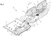
- Sectionally illustrated conductor rail system 1 has an elongate guide rail 2 and a cross-sectionally double-T-shaped rail track 3. On rail track 3 a conductor strand holder 4 is arranged for. Further arranged along the rail track 3 conductor strand holders are not shown in the drawing.
- the conductor strand holder 4 holds a total of six along the conductor rail 2 in a longitudinal direction L extending elongated insulating profiles, which are described below with reference to Insulating profile 5 will be described. The information on this applies accordingly to the other insulating profiles.
- an electrically conductive conductor strand 6 is used, which has a substantially C-shaped or U-shaped cross-section.
- the open side of the U-shaped cross-section of insulating profile 5 and conductor strand 6 show in Fig. 1 towards the viewer.
- one of the conductor strands used in the insulating profiles is a ground and / or protective conductor.
- the other conductor strands are current or live phase conductor strands and serve to supply by a transport hanger 7 indicated movable electrical loads with electrical energy.
- movable transport hanger 7 has an in Fig. 1 not shown electric drive motor for drive wheels 8.
- the drive wheels 8 run on the horizontal upper T-shaped portion of the rail track 3.
- the side of the transport hanger 7 is guided by side guide wheels 9.
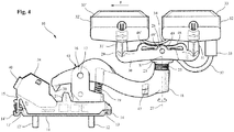
- pantograph is provided for each conductor strand, which by way of example in the Fig. 2 to 9 illustrated pantograph 10 is explained. Corresponding information also applies to the other pantographs.
- a support plate 11 is provided. This is struck by means of connecting screws 12, 12 'fixed to the inside of the downwardly projecting leg of the transport hanger 7.
- a fork-shaped support 16 rotatable about a rotation axis perpendicular to the support plate 11 is provided, on which a tilting arm 18 is rotatably arranged about a first rotation axis 17.
- the Kipparm 18 is a in FIGS. 2 to 5 in the prestressed state shown pressed coil spring 19 of the base 15 and thus pressed in the direction of the conductor strand 6.
- the coil spring 19 is arranged on an elongated projection of the bearing 16 and thus rotatable with the bearing 16 about the vertical axis of rotation on the support plate 11.
- a spiral spring other suitable elements can be used, which press the tilting arm 18 away from the base 15 and to the conductor strand 6.
- a mandrel 20 is provided which abuts against a arranged on the base 15 centering 21. This comes in particular to effect when the transport hanger 11 is removed with the pantograph 10 of the conductor rail 2 and then re-used.
- the centering mandrel 20 may preferably have a wedge-shaped or conical shape and engage in the corresponding internally wedge-shaped or internally tapered stop 21.
- the tilting arm 18 can advantageously be brought into a position running parallel to its travel direction F and to the longitudinal direction L of the conductor rail 2 in order to be able to introduce the current collector 10 cleanly into the conductor strand 6.
- FIGS. 2 to 5 Right end is inserted into a hollow cylindrical opening 22 of the rocker arm 18 is also a hollow cylindrical connector 23 of a bearing block 24.
- the connecting piece 23 is pressed by a further coil spring 25 to the conductor strand 6 and is secured by means of a latching connection 26 against falling out of the opening 22.
- the bearing block 22 yielding slightly in the direction of the conductor strand 6, whereby unevenness in the conductor strand 6 can be compensated.
- the rocker 29 On the bearing block 23 is rotatable about a second axis of rotation 27 a seen from the side substantially U-shaped rocker 29 with a connecting leg 30 is disposed at the ends of support legs 31, 31 ', each with a contact strip holder 32, 32' are arranged.
- the rocker 29 At least in the area between the support legs 31, 31 'and the bearing block 22, the rocker 29 has elongated recesses or hollows.
- Both the base 15 and the Kipparm 18, the bearing block 23 with the hollow cylindrical fitting 24 and the rocker 29 are made of plastic, in particular a hard plastic such. Hard plastic made.
- the rocker 29 and the Kipparm 18 are substantially movable in a running through the conductor strand 6 driving plane, apart from itself unwanted side movements, which may be caused by a non-exact course of the conductor strand, the conductor rail and the driving movement of the consumer.
- the driving plane is substantially perpendicular to a plane through the plurality of strands.
- the two sliding pieces 33, 33 ' are electrically conductively connected to each other via a connecting cable 34.
- a female connector 35 for a connector 36 is provided.
- the plug 36 is fixed to one end of a connection cable 37.
- the connection cable 37 is connected at its other, stripped end fixed to a terminal 38.
- the terminal 38 is connected via a designed as a dovetail connector 38 to the base 15. Via a further connection 40 of the connection terminal 38, a connecting line to one or more electrical consumers of the transport hanger 7 can then be produced.
- the connecting cable 37 is guided on its way from the socket 35 to the terminal 38 advantageously defined in a cable guide channel 41.
- the cable channel 41 in this case initially has an opening 42 in the bottom of the rocker 29, through which the cable 37 is inserted from the socket 34 coming between the two side walls of the rocker 29, in order then through the hollow cylindrical Connector 24 of the bearing block 23 to be performed. From there, the cable 37 is then guided through the front region of the tilting arm 18, which is preferably open on the underside. In this way, the cable 37 can be easily mounted, so that its free end can be guided around by a arranged adjacent to the bearing 16 opening 43 in the upper wall of the tilting arm 18 and then around two clamping legs 44, 44 'by clamping. Subsequently, the cable 37 is inserted through a further opening 45 in the shorter arm of the tilting arm 18 down and through a hollow cylindrical cable entry 46 into the base 15, where it is then still guided in the cable channel 40 to the terminal 38.
- a viewing window 47 in the longer part of the tilting arm 18 also allows from the side of a check whether the cable 37 is properly guided.
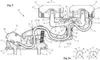
- rocker 29 In order to ensure that the contact strips 31, 31 'both bear on the conductor strand 6 as well as possible and uniformly, it can preferably be ensured that the rocker 29 automatically moves back into this rest position upon deflection from its rest position shown in the drawings.
- two symmetrically shaped spring arms 48, 48 ' are provided on the horizontal connecting leg of the rocker 29, which point in the direction of the bearing block 23.
- the spring arms 48, 48 ' have at their free ends thickened sliding contacts 49, 49', which can also slide on symmetrically designed sliding surfaces 50, 50 'of the bearing block 23.
- the sliding surfaces 50, 50 ' formed so that when moving the rocker 29 from the rest position that spring arm 48, 48', which is moved from its rest position away from the base 15 and to the conductor strand 6, is stretched while the other spring arm 48, 48 ', which is moved from its rest position to the base 15 and away from the conductor strand 6, is relaxed.
- the region of the sliding surfaces 50, 50 ' which extend from the rest position of the sliding contacts 49, 49' to the axis of symmetry S through the third axis of rotation 28, are steeper than an imaginary circle G with the radius R of the sliding contacts 49, 49 'about the axis of rotation 28.
- the other portion of the sliding surfaces 50, 50' may be less steep.
- This return mechanism is exemplary in Fig. 5a shown on the left.
- the sliding surfaces 50, 50 'as shown in detail of Fig. 5a be formed as a circular section with the radius R, which intersects with the imaginary circle G of the sliding contacts 49, 49 'in the rest position of the sliding contacts 49, 49' on the sliding surfaces 50, 50 'at the intersection P and P'.
- it is also possible to provide other configurations of the sliding surfaces which produce the same effect for example a straight sliding surface extending tangentially through the intersection P on the imaginary circle G.
- the spring arms 48, 48 'could also be provided on the bearing block 23, so that correspondingly sliding surfaces would be provided on the rocker 29, which upon a deflection of the rocker 29 from the inoperative position would stretch the spring arm which counteracts the deflection.
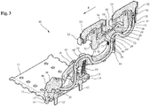
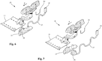
- Fig. 6 to 9 show again exploded views of in Fig. 2 to 5 illustrated in detail pantograph 10th
Landscapes
- Engineering & Computer Science (AREA)
- Power Engineering (AREA)
- Transportation (AREA)
- Mechanical Engineering (AREA)
- Current-Collector Devices For Electrically Propelled Vehicles (AREA)
Claims (15)
- Collecteur de courant (10) pour un consommateur électrique déplaçable dans un sens de marche (F) le long d'une ligne de contact (2), avec au moins deux frotteurs (33, 33') agencés l'un derrière l'autre dans le sens de marche (F) au niveau d'une bascule (29), dans lequel la bascule (29) est logée autour d'un axe de rotation (28) s'étendant perpendiculairement au sens de marche (F), au niveau d'un bras basculant (18), par lequel la bascule (29) peut être déplacée vers le fil conducteur (6) pour la mise en contact des frotteurs (33, 33') avec un fil conducteur (6) électroconducteur de la ligne de contact (2), caractérisé en ce qu'un premier bras ressort (48), qui glisse sur une première surface de glissement (50) associée au bras basculant (18), est agencé au niveau de la bascule (29), ou le premier bras ressort (48) est associé au bras basculant (18) et la première surface de glissement (50) est agencée au niveau de la bascule (29), dans lequel le premier bras ressort (48) est tendu lors de la déflexion de la bascule (29) hors d'une position de repos, et pousse la bascule (29) vers la position de repos.
- Collecteur de courant (10) selon la revendication 1, caractérisé en ce qu'un second bras ressort (48'), qui glisse sur une seconde surface de glissement (50') associée au bras basculant (18), est agencé au niveau de la bascule (29), ou le second bras ressort (48') est associé au bras basculant (18) et la seconde surface de glissement (50') est agencée au niveau de la bascule (29), dans lequel le premier bras ressort (48) est tendu lors de la déflexion de la bascule (29) hors de la position de repos dans un sens de rotation autour de l'axe de rotation (28), et pousse la bascule (29) dans le sens opposé au sens de rotation vers la position de repos, et le second bras ressort (48') est tendu lors de la déflexion de la bascule (29) hors de la position de repos dans l'autre sens de rotation, et pousse la bascule (29) dans le sens opposé à l'autre sens de rotation vers la position de repos.
- Collecteur de courant (10) selon la revendication 2, caractérisé en ce que les bras ressort (48, 48') agencés au niveau de la bascule (29) sont agencés sur des côtés de l'axe de rotation (28) opposés l'un l'autre dans le sens de marche (F) et sont orientés l'un vers l'autre.
- Collecteur de courant (10) selon l'une quelconque des revendications 2 à 3, caractérisé en ce que les bras ressort (48, 48') et/ou les surfaces de glissement (50, 50') sont réalisés symétriquement à un axe de symétrie (S) perpendiculaire au sens de marche (F) et s'étendant à travers l'axe de rotation (28).
- Collecteur de courant (10) selon l'une quelconque des revendications précédentes, caractérisé en ce que le ou les bras ressort (48, 48') présentent des contacts glissants (49, 49') épaissis au niveau de leur extrémité libre.
- Collecteur de courant (10) selon l'une quelconque des revendications précédentes, caractérisé en ce que les bras ressort (48, 48') et/ou les surfaces de glissement (50, 50') sont agencés au niveau d'un bloc-palier (23) du bras basculant (18).
- Collecteur de courant (10) selon la revendication 6, caractérisé en ce que le bloc-palier (23) est agencé au niveau du bras basculant (18) de manière rotative autour d'un autre axe de rotation (28) perpendiculaire à l'axe de rotation (28) de la bascule (29) et au sens de marche (F).
- Collecteur de courant (10) selon l'une quelconque des revendications 6 ou 7, caractérisé en ce que le bloc-palier (23) présente un raccord cylindrique creux (24), lequel est enfiché dans une ouverture cylindrique creuse (22) correspondante du bras basculant (18).
- Collecteur de courant (10) selon l'une quelconque des revendications précédentes, caractérisé en ce que le bras basculant (18) est agencé au niveau d'une base (15) de manière rotative autour d'un autre axe de rotation (17) perpendiculaire au sens de marche (F) et s'étendant parallèlement à l'axe de rotation (28) de la bascule (29), dans lequel le bras basculant (18) est poussé par un ressort (19) à l'opposé de la base (15) et vers le fil conducteur (6).
- Collecteur de courant (10) selon la revendication 9, caractérisé en ce que la base (15) peut être clipsée sur une plaque de support (11) au moyen de liaisons par encliquetage (14, 14').
- Collecteur de courant (10) selon l'une quelconque des revendications précédentes, caractérisé en ce que le ou les bras ressort (48, 48') sont fabriqués d'un seul tenant avec la bascule (29) ou le bloc-palier (23).
- Collecteur de courant (10) selon l'une quelconque des revendications précédentes, caractérisé en ce que le ou les bras ressort (48, 48') sont prévus au niveau d'une branche de liaison (30) de la bascule (29).
- Collecteur de courant (10) selon l'une quelconque des revendications précédentes, caractérisé en ce qu'au moins la première surface de glissement (50) est réalisée de sorte que le premier bras ressort (48) est plus tendu lors du déplacement hors de la position de repos que dans la position de repos.
- Collecteur de courant (10) selon la revendication 13, caractérisé en ce que le premier bras ressort (48) dans la position de repos touche la surface de glissement (50), et une zone de la surface de glissement (50) s'y raccordant est réalisée de sorte que le premier bras ressort (48) est plus tendu dans une direction lors du déplacement hors de la position de repos que dans la position de repos.
- Système de ligne de contact (1) avec une ligne de contact (2) et au moins un consommateur électrique déplaçable au niveau de la ligne de contact (2) dans son sens longitudinal, dans lequel la ligne de contact (2) présente au moins un fil conducteur (6) électroconducteur pour la mise en contact en glissement avec au moins deux frotteurs (33, 33') d'un collecteur de courant (10), caractérisé en ce que le collecteur de courant (10) est réalisé selon l'une quelconque des revendications 1 à 14.
Applications Claiming Priority (2)
| Application Number | Priority Date | Filing Date | Title |
|---|---|---|---|
| DE102015101849.7A DE102015101849A1 (de) | 2015-02-10 | 2015-02-10 | Stromabnehmer und Schleifleitungssystem |
| PCT/EP2015/074567 WO2016128076A1 (fr) | 2015-02-10 | 2015-10-23 | Collecteur de courant et système de ligne de contact |
Publications (2)
| Publication Number | Publication Date |
|---|---|
| EP3083322A1 EP3083322A1 (fr) | 2016-10-26 |
| EP3083322B1 true EP3083322B1 (fr) | 2019-04-24 |
Family
ID=54347538
Family Applications (1)
| Application Number | Title | Priority Date | Filing Date |
|---|---|---|---|
| EP15784682.5A Active EP3083322B1 (fr) | 2015-02-10 | 2015-10-23 | Collecteur de courant et système de ligne de contact |
Country Status (4)
| Country | Link |
|---|---|
| US (1) | US10525830B2 (fr) |
| EP (1) | EP3083322B1 (fr) |
| DE (1) | DE102015101849A1 (fr) |
| WO (1) | WO2016128076A1 (fr) |
Cited By (1)
| Publication number | Priority date | Publication date | Assignee | Title |
|---|---|---|---|---|
| US20240006835A1 (en) * | 2022-01-18 | 2024-01-04 | Caterpillar Global Mining Equipment Llc | Slidable current collector and method for contacting conductor rail |
Families Citing this family (12)
| Publication number | Priority date | Publication date | Assignee | Title |
|---|---|---|---|---|
| DE102014107468A1 (de) * | 2014-05-27 | 2015-12-03 | Conductix-Wampfler Gmbh | Schleifleitung, Stromabnehmer und Schleifleitungssystem |
| DE102015101849A1 (de) * | 2015-02-10 | 2016-08-11 | Conductix-Wampfler Gmbh | Stromabnehmer und Schleifleitungssystem |
| DE202017107220U1 (de) | 2017-11-28 | 2019-03-01 | Conductix-Wampfler Gmbh | Stromabnehmer und Schleifleitungssystem |
| DE102017128173A1 (de) | 2017-11-28 | 2019-05-29 | Conductix-Wampfler Gmbh | Stromabnehmer und Schleifleitungssystem |
| CN110194060B (zh) * | 2018-02-27 | 2021-04-20 | 比亚迪股份有限公司 | 受流器及具有其的电力机车 |
| CN110803040B (zh) * | 2018-08-01 | 2022-03-18 | 比亚迪股份有限公司 | 充电刀总成及具有其的轨道车辆、轨道车辆交通系统 |
| DE102020123266A1 (de) | 2020-09-07 | 2022-03-10 | Conductix-Wampfler Gmbh | Stromabnehmer |
| DE202020105139U1 (de) | 2020-09-07 | 2021-12-08 | Conductix-Wampfler Gmbh | Stromabnehmer |
| DE102022103679A1 (de) | 2022-02-16 | 2023-08-17 | Conductix-Wampfler Gmbh | Stromabnehmer und Schleifleitungssystem |
| DE202022100889U1 (de) | 2022-02-16 | 2023-06-14 | Conductix-Wampfler Gmbh | Stromabnehmer und Schleifleitungssystem |
| DE102024119386A1 (de) * | 2024-07-08 | 2026-01-08 | DETO Holding GmbH | Stromabnehmereinheit mit Sensorsystem |
| DE102024119384A1 (de) * | 2024-07-08 | 2026-01-08 | DETO Holding GmbH | Stromabnehmersystem zum Beziehen eines Stroms von einer Schleifleitung |
Family Cites Families (17)
| Publication number | Priority date | Publication date | Assignee | Title |
|---|---|---|---|---|
| US1826854A (en) * | 1930-03-13 | 1931-10-13 | Charles L Wilmot | Trolley |
| US3396246A (en) * | 1968-01-02 | 1968-08-06 | Rucker Mfg Company | Tandem collector assembly for overhead electrification system |
| FR2320204A1 (fr) * | 1975-08-07 | 1977-03-04 | Gennevilliers Acieries | Nouvelle prise de courant pour vehicule electrique alimente a partir d'un conducteur aerien |
| DE3018428A1 (de) | 1980-05-14 | 1981-11-19 | Translift AG, 6010 Kriens, Luzern | Steuerstromuebertrager in form einer an eine steuerstromschiene federnd anliegenden kontaktgeberanordnung fuer fahrwerke in foerdersystemen |
| US4464546A (en) * | 1981-11-23 | 1984-08-07 | Westinghouse Electric Corp. | Power collection apparatus for a vehicle |
| FR2600287B2 (fr) | 1985-11-20 | 1988-10-21 | Delachaux Sa | Tete de trolleybus |
| DE3610455A1 (de) | 1986-03-27 | 1987-10-01 | Vahle Paul Kg | Schwenkbarer kipparm-stromabnehmer |
| JPS63202202A (ja) | 1987-02-13 | 1988-08-22 | Matsushita Electric Works Ltd | 絶縁トロリ−の集電装置 |
| DE9004828U1 (de) | 1990-04-27 | 1991-08-29 | Wampfler Gmbh, 7858 Weil | Stromabnehmer |
| JPH04193003A (ja) * | 1990-11-27 | 1992-07-13 | H S S T:Kk | 走行体用集電装置 |
| DE19540914C2 (de) | 1995-11-03 | 2000-11-16 | Deutsch Zentr Luft & Raumfahrt | Stromabnehmer für die Energieübertragung zwischen einem Fahrdraht und einem Triebwagen |
| DE19541600C1 (de) * | 1995-11-08 | 1997-07-17 | Deutsche Forsch Luft Raumfahrt | Stromabnehmer für die Energieübertragung zwischen einem Fahrdraht und einem Triebwagen |
| US6152273A (en) * | 1998-02-20 | 2000-11-28 | Magnetek, Inc. | Universal arm and mounting block for a current collector |
| DE20205710U1 (de) | 2002-04-11 | 2002-08-14 | Fahrleitungsbau GmbH, 45329 Essen | Stromabnehmer |
| DE102011076620A1 (de) * | 2011-05-27 | 2012-11-29 | Siemens Aktiengesellschaft | Nicht schienengebundenes Fahrzeug |
| DE102015101849A1 (de) * | 2015-02-10 | 2016-08-11 | Conductix-Wampfler Gmbh | Stromabnehmer und Schleifleitungssystem |
| DE102015101848B4 (de) * | 2015-02-10 | 2021-02-11 | Conductix-Wampfler Gmbh | Stromabnehmer und Schleifleitungssystem |
-
2015
- 2015-02-10 DE DE102015101849.7A patent/DE102015101849A1/de not_active Withdrawn
- 2015-10-23 US US15/307,840 patent/US10525830B2/en active Active
- 2015-10-23 EP EP15784682.5A patent/EP3083322B1/fr active Active
- 2015-10-23 WO PCT/EP2015/074567 patent/WO2016128076A1/fr not_active Ceased
Non-Patent Citations (1)
| Title |
|---|
| None * |
Cited By (1)
| Publication number | Priority date | Publication date | Assignee | Title |
|---|---|---|---|---|
| US20240006835A1 (en) * | 2022-01-18 | 2024-01-04 | Caterpillar Global Mining Equipment Llc | Slidable current collector and method for contacting conductor rail |
Also Published As
| Publication number | Publication date |
|---|---|
| DE102015101849A1 (de) | 2016-08-11 |
| US10525830B2 (en) | 2020-01-07 |
| US20170057359A1 (en) | 2017-03-02 |
| EP3083322A1 (fr) | 2016-10-26 |
| WO2016128076A1 (fr) | 2016-08-18 |
Similar Documents
| Publication | Publication Date | Title |
|---|---|---|
| EP3083322B1 (fr) | Collecteur de courant et système de ligne de contact | |
| EP3359412B1 (fr) | Système de charge rapide et procédé pour la liaison électrique d'un véhicule à un poste de charge | |
| DE102015101848B4 (de) | Stromabnehmer und Schleifleitungssystem | |
| EP3031104B1 (fr) | Systeme de recharge rapide et procede de montage d'un dispositif de contact sur un dispositif de support | |
| EP2324542B2 (fr) | Ligne de contact, prise de courant et système de ligne de contact | |
| EP3084940B9 (fr) | Système transporteur linéaire et procédé de fonctionnement du système transporteur linéaire | |
| EP2969637B1 (fr) | Ligne de contact, balai conducteur et système de ligne de contact équipé d'un guide d'ondes à fente destiné à recevoir une antenne | |
| EP2964481B2 (fr) | Ligne à frottement, collecteur de courant et système à ligne à frottement | |
| EP3160816B1 (fr) | Installation de téléphérique | |
| EP3765325B1 (fr) | Systeme de charge rapide et procede de connexion electrique d'un vehicule a une station de charge | |
| EP3386832B1 (fr) | Véhicule, en particulier véhicule ferroviaire | |
| EP2683570A2 (fr) | Attache pour un conducteur de données, système de transmission d'énergie et système de transmission de données | |
| DE102017128173A1 (de) | Stromabnehmer und Schleifleitungssystem | |
| EP2958768B1 (fr) | Dispositif d'établissement d'un contact électrique avec un système de conducteurs de contact | |
| DE202015100622U1 (de) | Stromabnehmer und Schleifleitungssystem | |
| DE19917309A1 (de) | Stromabnehmer | |
| DE202015100623U1 (de) | Stromabnehmer und Schleifleitungssystem | |
| WO2021018909A1 (fr) | Station de distribution et procédé pour faire fonctionner une station de distribution pour la production automatisée d'un faisceau de câblage | |
| DE4008196A1 (de) | Transportvorrichtung fuer werkstuecke | |
| DE202017107220U1 (de) | Stromabnehmer und Schleifleitungssystem | |
| DE202008011700U1 (de) | Schleifleitung, Stromabnehmer und Schleifleitungssystem | |
| DE102023131552A1 (de) | Verbindungselement, Schleifleitung, Stromabnehmerwagen und Schleifleitungssystem | |
| DE60209136T2 (de) | Verbindung für fahrdrähte | |
| DE202014102489U1 (de) | Schleifleitung, Stromabnehmer und Schleifleitungssystem |
Legal Events
| Date | Code | Title | Description |
|---|---|---|---|
| PUAI | Public reference made under article 153(3) epc to a published international application that has entered the european phase |
Free format text: ORIGINAL CODE: 0009012 |
|
| 17P | Request for examination filed |
Effective date: 20160427 |
|
| AK | Designated contracting states |
Kind code of ref document: A1 Designated state(s): AL AT BE BG CH CY CZ DE DK EE ES FI FR GB GR HR HU IE IS IT LI LT LU LV MC MK MT NL NO PL PT RO RS SE SI SK SM TR |
|
| AX | Request for extension of the european patent |
Extension state: BA ME |
|
| DAV | Request for validation of the european patent (deleted) | ||
| DAX | Request for extension of the european patent (deleted) | ||
| STAA | Information on the status of an ep patent application or granted ep patent |
Free format text: STATUS: EXAMINATION IS IN PROGRESS |
|
| 17Q | First examination report despatched |
Effective date: 20180528 |
|
| GRAP | Despatch of communication of intention to grant a patent |
Free format text: ORIGINAL CODE: EPIDOSNIGR1 |
|
| STAA | Information on the status of an ep patent application or granted ep patent |
Free format text: STATUS: GRANT OF PATENT IS INTENDED |
|
| RIC1 | Information provided on ipc code assigned before grant |
Ipc: B60L 5/08 20060101AFI20181126BHEP Ipc: B60L 5/16 20060101ALI20181126BHEP Ipc: B60L 5/40 20060101ALI20181126BHEP |
|
| INTG | Intention to grant announced |
Effective date: 20181217 |
|
| GRAS | Grant fee paid |
Free format text: ORIGINAL CODE: EPIDOSNIGR3 |
|
| GRAA | (expected) grant |
Free format text: ORIGINAL CODE: 0009210 |
|
| STAA | Information on the status of an ep patent application or granted ep patent |
Free format text: STATUS: THE PATENT HAS BEEN GRANTED |
|
| AK | Designated contracting states |
Kind code of ref document: B1 Designated state(s): AL AT BE BG CH CY CZ DE DK EE ES FI FR GB GR HR HU IE IS IT LI LT LU LV MC MK MT NL NO PL PT RO RS SE SI SK SM TR |
|
| REG | Reference to a national code |
Ref country code: GB Ref legal event code: FG4D Free format text: NOT ENGLISH |
|
| REG | Reference to a national code |
Ref country code: CH Ref legal event code: EP |
|
| REG | Reference to a national code |
Ref country code: DE Ref legal event code: R096 Ref document number: 502015008820 Country of ref document: DE |
|
| REG | Reference to a national code |
Ref country code: AT Ref legal event code: REF Ref document number: 1123727 Country of ref document: AT Kind code of ref document: T Effective date: 20190515 Ref country code: IE Ref legal event code: FG4D Free format text: LANGUAGE OF EP DOCUMENT: GERMAN |
|
| REG | Reference to a national code |
Ref country code: NL Ref legal event code: MP Effective date: 20190424 |
|
| REG | Reference to a national code |
Ref country code: LT Ref legal event code: MG4D |
|
| PG25 | Lapsed in a contracting state [announced via postgrant information from national office to epo] |
Ref country code: NL Free format text: LAPSE BECAUSE OF FAILURE TO SUBMIT A TRANSLATION OF THE DESCRIPTION OR TO PAY THE FEE WITHIN THE PRESCRIBED TIME-LIMIT Effective date: 20190424 |
|
| PG25 | Lapsed in a contracting state [announced via postgrant information from national office to epo] |
Ref country code: LT Free format text: LAPSE BECAUSE OF FAILURE TO SUBMIT A TRANSLATION OF THE DESCRIPTION OR TO PAY THE FEE WITHIN THE PRESCRIBED TIME-LIMIT Effective date: 20190424 Ref country code: HR Free format text: LAPSE BECAUSE OF FAILURE TO SUBMIT A TRANSLATION OF THE DESCRIPTION OR TO PAY THE FEE WITHIN THE PRESCRIBED TIME-LIMIT Effective date: 20190424 Ref country code: NO Free format text: LAPSE BECAUSE OF FAILURE TO SUBMIT A TRANSLATION OF THE DESCRIPTION OR TO PAY THE FEE WITHIN THE PRESCRIBED TIME-LIMIT Effective date: 20190724 Ref country code: SE Free format text: LAPSE BECAUSE OF FAILURE TO SUBMIT A TRANSLATION OF THE DESCRIPTION OR TO PAY THE FEE WITHIN THE PRESCRIBED TIME-LIMIT Effective date: 20190424 Ref country code: ES Free format text: LAPSE BECAUSE OF FAILURE TO SUBMIT A TRANSLATION OF THE DESCRIPTION OR TO PAY THE FEE WITHIN THE PRESCRIBED TIME-LIMIT Effective date: 20190424 Ref country code: PT Free format text: LAPSE BECAUSE OF FAILURE TO SUBMIT A TRANSLATION OF THE DESCRIPTION OR TO PAY THE FEE WITHIN THE PRESCRIBED TIME-LIMIT Effective date: 20190824 Ref country code: AL Free format text: LAPSE BECAUSE OF FAILURE TO SUBMIT A TRANSLATION OF THE DESCRIPTION OR TO PAY THE FEE WITHIN THE PRESCRIBED TIME-LIMIT Effective date: 20190424 Ref country code: FI Free format text: LAPSE BECAUSE OF FAILURE TO SUBMIT A TRANSLATION OF THE DESCRIPTION OR TO PAY THE FEE WITHIN THE PRESCRIBED TIME-LIMIT Effective date: 20190424 |
|
| PG25 | Lapsed in a contracting state [announced via postgrant information from national office to epo] |
Ref country code: BG Free format text: LAPSE BECAUSE OF FAILURE TO SUBMIT A TRANSLATION OF THE DESCRIPTION OR TO PAY THE FEE WITHIN THE PRESCRIBED TIME-LIMIT Effective date: 20190724 Ref country code: GR Free format text: LAPSE BECAUSE OF FAILURE TO SUBMIT A TRANSLATION OF THE DESCRIPTION OR TO PAY THE FEE WITHIN THE PRESCRIBED TIME-LIMIT Effective date: 20190725 Ref country code: LV Free format text: LAPSE BECAUSE OF FAILURE TO SUBMIT A TRANSLATION OF THE DESCRIPTION OR TO PAY THE FEE WITHIN THE PRESCRIBED TIME-LIMIT Effective date: 20190424 Ref country code: RS Free format text: LAPSE BECAUSE OF FAILURE TO SUBMIT A TRANSLATION OF THE DESCRIPTION OR TO PAY THE FEE WITHIN THE PRESCRIBED TIME-LIMIT Effective date: 20190424 Ref country code: PL Free format text: LAPSE BECAUSE OF FAILURE TO SUBMIT A TRANSLATION OF THE DESCRIPTION OR TO PAY THE FEE WITHIN THE PRESCRIBED TIME-LIMIT Effective date: 20190424 |
|
| PG25 | Lapsed in a contracting state [announced via postgrant information from national office to epo] |
Ref country code: IS Free format text: LAPSE BECAUSE OF FAILURE TO SUBMIT A TRANSLATION OF THE DESCRIPTION OR TO PAY THE FEE WITHIN THE PRESCRIBED TIME-LIMIT Effective date: 20190824 |
|
| REG | Reference to a national code |
Ref country code: DE Ref legal event code: R097 Ref document number: 502015008820 Country of ref document: DE |
|
| PG25 | Lapsed in a contracting state [announced via postgrant information from national office to epo] |
Ref country code: SK Free format text: LAPSE BECAUSE OF FAILURE TO SUBMIT A TRANSLATION OF THE DESCRIPTION OR TO PAY THE FEE WITHIN THE PRESCRIBED TIME-LIMIT Effective date: 20190424 Ref country code: CZ Free format text: LAPSE BECAUSE OF FAILURE TO SUBMIT A TRANSLATION OF THE DESCRIPTION OR TO PAY THE FEE WITHIN THE PRESCRIBED TIME-LIMIT Effective date: 20190424 Ref country code: DK Free format text: LAPSE BECAUSE OF FAILURE TO SUBMIT A TRANSLATION OF THE DESCRIPTION OR TO PAY THE FEE WITHIN THE PRESCRIBED TIME-LIMIT Effective date: 20190424 Ref country code: RO Free format text: LAPSE BECAUSE OF FAILURE TO SUBMIT A TRANSLATION OF THE DESCRIPTION OR TO PAY THE FEE WITHIN THE PRESCRIBED TIME-LIMIT Effective date: 20190424 Ref country code: EE Free format text: LAPSE BECAUSE OF FAILURE TO SUBMIT A TRANSLATION OF THE DESCRIPTION OR TO PAY THE FEE WITHIN THE PRESCRIBED TIME-LIMIT Effective date: 20190424 |
|
| PG25 | Lapsed in a contracting state [announced via postgrant information from national office to epo] |
Ref country code: SM Free format text: LAPSE BECAUSE OF FAILURE TO SUBMIT A TRANSLATION OF THE DESCRIPTION OR TO PAY THE FEE WITHIN THE PRESCRIBED TIME-LIMIT Effective date: 20190424 |
|
| PLBE | No opposition filed within time limit |
Free format text: ORIGINAL CODE: 0009261 |
|
| STAA | Information on the status of an ep patent application or granted ep patent |
Free format text: STATUS: NO OPPOSITION FILED WITHIN TIME LIMIT |
|
| PG25 | Lapsed in a contracting state [announced via postgrant information from national office to epo] |
Ref country code: TR Free format text: LAPSE BECAUSE OF FAILURE TO SUBMIT A TRANSLATION OF THE DESCRIPTION OR TO PAY THE FEE WITHIN THE PRESCRIBED TIME-LIMIT Effective date: 20190424 |
|
| 26N | No opposition filed |
Effective date: 20200127 |
|
| PG25 | Lapsed in a contracting state [announced via postgrant information from national office to epo] |
Ref country code: MC Free format text: LAPSE BECAUSE OF FAILURE TO SUBMIT A TRANSLATION OF THE DESCRIPTION OR TO PAY THE FEE WITHIN THE PRESCRIBED TIME-LIMIT Effective date: 20190424 Ref country code: SI Free format text: LAPSE BECAUSE OF FAILURE TO SUBMIT A TRANSLATION OF THE DESCRIPTION OR TO PAY THE FEE WITHIN THE PRESCRIBED TIME-LIMIT Effective date: 20190424 |
|
| REG | Reference to a national code |
Ref country code: CH Ref legal event code: PL |
|
| PG25 | Lapsed in a contracting state [announced via postgrant information from national office to epo] |
Ref country code: CH Free format text: LAPSE BECAUSE OF NON-PAYMENT OF DUE FEES Effective date: 20191031 Ref country code: LU Free format text: LAPSE BECAUSE OF NON-PAYMENT OF DUE FEES Effective date: 20191023 Ref country code: LI Free format text: LAPSE BECAUSE OF NON-PAYMENT OF DUE FEES Effective date: 20191031 |
|
| REG | Reference to a national code |
Ref country code: BE Ref legal event code: MM Effective date: 20191031 |
|
| PG25 | Lapsed in a contracting state [announced via postgrant information from national office to epo] |
Ref country code: BE Free format text: LAPSE BECAUSE OF NON-PAYMENT OF DUE FEES Effective date: 20191031 |
|
| GBPC | Gb: european patent ceased through non-payment of renewal fee |
Effective date: 20191023 |
|
| PG25 | Lapsed in a contracting state [announced via postgrant information from national office to epo] |
Ref country code: IE Free format text: LAPSE BECAUSE OF NON-PAYMENT OF DUE FEES Effective date: 20191023 Ref country code: GB Free format text: LAPSE BECAUSE OF NON-PAYMENT OF DUE FEES Effective date: 20191023 |
|
| PG25 | Lapsed in a contracting state [announced via postgrant information from national office to epo] |
Ref country code: CY Free format text: LAPSE BECAUSE OF FAILURE TO SUBMIT A TRANSLATION OF THE DESCRIPTION OR TO PAY THE FEE WITHIN THE PRESCRIBED TIME-LIMIT Effective date: 20190424 |
|
| PG25 | Lapsed in a contracting state [announced via postgrant information from national office to epo] |
Ref country code: MT Free format text: LAPSE BECAUSE OF FAILURE TO SUBMIT A TRANSLATION OF THE DESCRIPTION OR TO PAY THE FEE WITHIN THE PRESCRIBED TIME-LIMIT Effective date: 20190424 Ref country code: HU Free format text: LAPSE BECAUSE OF FAILURE TO SUBMIT A TRANSLATION OF THE DESCRIPTION OR TO PAY THE FEE WITHIN THE PRESCRIBED TIME-LIMIT; INVALID AB INITIO Effective date: 20151023 |
|
| PG25 | Lapsed in a contracting state [announced via postgrant information from national office to epo] |
Ref country code: MK Free format text: LAPSE BECAUSE OF FAILURE TO SUBMIT A TRANSLATION OF THE DESCRIPTION OR TO PAY THE FEE WITHIN THE PRESCRIBED TIME-LIMIT Effective date: 20190424 |
|
| P01 | Opt-out of the competence of the unified patent court (upc) registered |
Effective date: 20230508 |
|
| PGFP | Annual fee paid to national office [announced via postgrant information from national office to epo] |
Ref country code: DE Payment date: 20251106 Year of fee payment: 11 |
|
| PGFP | Annual fee paid to national office [announced via postgrant information from national office to epo] |
Ref country code: AT Payment date: 20251021 Year of fee payment: 11 |
|
| PGFP | Annual fee paid to national office [announced via postgrant information from national office to epo] |
Ref country code: IT Payment date: 20251031 Year of fee payment: 11 |
|
| PGFP | Annual fee paid to national office [announced via postgrant information from national office to epo] |
Ref country code: FR Payment date: 20251024 Year of fee payment: 11 |