EP3083322B1 - Current collector and conductor line system - Google Patents
Current collector and conductor line system Download PDFInfo
- Publication number
- EP3083322B1 EP3083322B1 EP15784682.5A EP15784682A EP3083322B1 EP 3083322 B1 EP3083322 B1 EP 3083322B1 EP 15784682 A EP15784682 A EP 15784682A EP 3083322 B1 EP3083322 B1 EP 3083322B1
- Authority
- EP
- European Patent Office
- Prior art keywords
- rocker
- current collector
- arm
- rest position
- spring
- Prior art date
- Legal status (The legal status is an assumption and is not a legal conclusion. Google has not performed a legal analysis and makes no representation as to the accuracy of the status listed.)
- Active
Links
Images


Classifications
-
- B—PERFORMING OPERATIONS; TRANSPORTING
- B60—VEHICLES IN GENERAL
- B60L—PROPULSION OF ELECTRICALLY-PROPELLED VEHICLES; SUPPLYING ELECTRIC POWER FOR AUXILIARY EQUIPMENT OF ELECTRICALLY-PROPELLED VEHICLES; ELECTRODYNAMIC BRAKE SYSTEMS FOR VEHICLES IN GENERAL; MAGNETIC SUSPENSION OR LEVITATION FOR VEHICLES; MONITORING OPERATING VARIABLES OF ELECTRICALLY-PROPELLED VEHICLES; ELECTRIC SAFETY DEVICES FOR ELECTRICALLY-PROPELLED VEHICLES
- B60L5/00—Current collectors for power supply lines of electrically-propelled vehicles
- B60L5/04—Current collectors for power supply lines of electrically-propelled vehicles using rollers or sliding shoes in contact with trolley wire
- B60L5/08—Structure of the sliding shoes or their carrying means
-
- B—PERFORMING OPERATIONS; TRANSPORTING
- B60—VEHICLES IN GENERAL
- B60L—PROPULSION OF ELECTRICALLY-PROPELLED VEHICLES; SUPPLYING ELECTRIC POWER FOR AUXILIARY EQUIPMENT OF ELECTRICALLY-PROPELLED VEHICLES; ELECTRODYNAMIC BRAKE SYSTEMS FOR VEHICLES IN GENERAL; MAGNETIC SUSPENSION OR LEVITATION FOR VEHICLES; MONITORING OPERATING VARIABLES OF ELECTRICALLY-PROPELLED VEHICLES; ELECTRIC SAFETY DEVICES FOR ELECTRICALLY-PROPELLED VEHICLES
- B60L5/00—Current collectors for power supply lines of electrically-propelled vehicles
- B60L5/04—Current collectors for power supply lines of electrically-propelled vehicles using rollers or sliding shoes in contact with trolley wire
- B60L5/12—Structural features of poles or their bases
- B60L5/16—Devices for lifting and resetting the collector
-
- B—PERFORMING OPERATIONS; TRANSPORTING
- B60—VEHICLES IN GENERAL
- B60L—PROPULSION OF ELECTRICALLY-PROPELLED VEHICLES; SUPPLYING ELECTRIC POWER FOR AUXILIARY EQUIPMENT OF ELECTRICALLY-PROPELLED VEHICLES; ELECTRODYNAMIC BRAKE SYSTEMS FOR VEHICLES IN GENERAL; MAGNETIC SUSPENSION OR LEVITATION FOR VEHICLES; MONITORING OPERATING VARIABLES OF ELECTRICALLY-PROPELLED VEHICLES; ELECTRIC SAFETY DEVICES FOR ELECTRICALLY-PROPELLED VEHICLES
- B60L5/00—Current collectors for power supply lines of electrically-propelled vehicles
- B60L5/40—Current collectors for power supply lines of electrically-propelled vehicles for collecting current from lines in slotted conduits
Definitions
- the invention relates to a current collector for a conductor rail according to the preamble of claim 1 and a conductor rail system according to the preamble of claim 15.
- conductor rail systems travels a movable electrical load along a conductor rail.
- the supply of the consumer with electrical energy is carried out via a current collector whose sliding contacts engage in conductor strands of the conductor rail.
- the consumer may e.g. a Transportge Kunststoff a rail overhead railway, a movable on rails trolley or so-called.
- E-RTG container cranes which are equipped with an electric traction drive, which is supplied by the conductor rail with electrical energy.
- the US 3,396,246 A discloses a pantograph for along a contact wire movable electrical load with two successively arranged, each arranged on a separate lever arm sliders.
- the two arms are each arranged rotatably about a common axis of rotation on a fork support and are pulled together by two coil springs.
- the ends of the coil springs are each guided by holes in the arms. This separate arrangement of the two arms is expensive and requires the installation of two separate coil springs.
- the US 1,826,854 A discloses a pantograph for along a contact wire movable electrical loads, which can tapped by means of two successively arranged rollers current from the contact wire.
- the current collector rollers are connected via short leads with sliding contacts a slip ring assembly.
- the fixed relative to the sliding contacts contact surfaces of the slip ring assembly are arranged on an arm, which in turn is arranged on a base. From the fixed contact surfaces of the slip ring assembly supply leads go to a second, arranged on the base slip ring assembly. This construction is complicated due to the two slip ring assemblies and at least in the region of the unshielded first slip ring arrangement to the touch.
- the EP 0 226 497 B1 discloses a pantograph head for a trolleybus in which the leads are routed between a high angle sliding contact and a terminal partially in a rotatable arm of the pantograph, and are partially exposed in open areas. In the open areas, there is a risk that the cables will be damaged or stuck from the outside. Furthermore, the lines between the sliding contact and the terminal are not defined guided or fixed, so that they hinder the movements of the arm and the sliding contact due to their current position. In addition, the lines are thereby constantly moved back and forth, so that the electrically conductive wires damaged and the insulation can be aborted. So there is also a risk of injury to persons when the wires are in places blank.
- the DE 30 18 428 A1 discloses a control current transformer with a resiliently applied to a control busbar contactor arrangement for trolleys in conveyor systems. Even there, the control power lines are only partially protected and guided largely freely movable through an elongated housing. Again, there is a risk that the control power lines or their insulation will be damaged by constant movements of the Steuerstromübertragers and the contactor assembly.
- the connecting line to the contact strips is also largely free and fixed only at one point of the pantograph with a clamp from a piece of sheet metal. Especially in the field of clamp there is a risk that the sharp sheet damage the insulation of the line. Otherwise, there is a risk that the line hooked or departed.
- the DE 36 10 455 A1 discloses a pantograph head having two sliders disposed on a rotatably mounted rocker. A tilting area of the rocker is limited by stops on the bearing of the rocker. However, between the attacks, the rocker can be freely moved back and forth, so that no optimal system is ensured on the conductor strand of the conductor rail. Also runs there, the connecting line of the grinding pieces away largely free and unprotected.
- the FR 2 320 204 A1 discloses a sliding line arrangement for the contact wire of a bus or the like, wherein there two sliding pieces are arranged on a rocker, which is rotatable about a transverse to its longitudinal direction horizontal axis of rotation on a tilting arm.
- the rotary arm in turn is arranged rotatably about a vertical axis of rotation on Kipparm.
- a guide slot is guided in a guide bush in the rotational direction about the axis of rotation, wherein the guide bush is centered by two coil springs between the lateral limbs of the rocker arm.
- the rocker is always seen from above centered on the longitudinal axis of the tilting arm, and thereby rotated about the vertical axis of rotation, but not about the horizontal axis of rotation of the rocker.
- One way to keep the entire rocker with the two grinding pieces evenly to the conductor rail is not there.
- the EP 0 453 721 A1 discloses a pantograph for contact rails having a base portion to which is hinged an arm carrying a U-shaped sliding contact carrier having sliding contacts disposed on its limbs in holders.
- the holders can be brought into a neutral position relative to the U-shaped sliding contact carrier, that in each case a resilient tab is provided on each holder, which is held between two pins at each outer ends of the sliding contact carrier.
- the disadvantage here is the complex construction, wherein only the two holders can be brought into neutral position, while the U-shaped sliding contact carrier thereby can not be brought into a desired position in which the two sliding pieces can be pressed evenly against the conductor rail.
- the DE 195 40 914 A1 discloses a current collector for the transmission of energy between a contact wire and a railcar, wherein one of the pantograph at least one sliding piece and a support arm for lifting the sliding piece and for applying a contact force with which the sliding piece in the energy transfer from below to the Contact wire rests, has.
- the support arm is pivotally mounted about a horizontal axis on the railcar and erectable with a lifting device about the axis by means of a fast actuator.
- the actuator is controlled by means of a controller in response to the signal of at least one arranged on the current collector force or acceleration sensor to keep the contact force of the contact strip to the contact wire constant. This is metrologically expensive and requires a costly fast actuator.
- the object of the invention is therefore to provide a current collector and a conductor rail system, which overcome the above-mentioned disadvantages and allow safe guidance of the pantograph contact in the conductor strand of the conductor rail and a reliable energy transfer.
- the invention solves the problem by a current collector with the features of claim 1 and a conductor rail system having the features of claim 15.
- Advantageous developments and refinements of the invention are specified in the dependent claims.
- the aforementioned pantograph according to the invention is characterized in that on the rocker a first spring arm is arranged, which slides on a Kipparm associated first sliding surface, or the first spring arm associated Kipparm and the first sliding surface is arranged on the rocker, wherein the first spring arm when the rocker is deflected out of a rest position, the rocker is pressed towards the rest position.
- This can ensure that the two contact pieces of the rocker are always pressed optimally and evenly to the conductor strand.
- a lifting of the sliding pieces which leads to a poorer energy transfer and possibly also to unwanted flashovers between the conductor strand and grinding pieces, can thus be largely avoided.
- a uniform wear of the grinding pieces can be achieved, so that maintenance intervals for the replacement of the grinding pieces increases and thereby conditional downtime of the system can be reduced.
- a second spring arm can be arranged on the rocker, which slides on a Kipparm associated second sliding surface, wherein the first spring arm upon deflection of the rocker from the rest position in a rotational direction about the Is pivoted rotation axis and the rocker against the direction of rotation to the rest position pushes, and the second spring arm is stretched in deflection of the rocker from the rest position in the other direction and presses the rocker against the other direction of rotation to the rest position.
- the second spring arm associated with the Kipparm and the second sliding surface may be arranged on the rocker, so the arrangement of spring arm and sliding surface are reversed.
- the spring arms arranged on the rocker can preferably be arranged on mutually opposite sides of the axis of rotation in the travel direction and directed toward one another.
- the spring arms have as in the direction of the axis of rotation or a reaching through this axis of symmetry.
- arranged on the tilt arm spring arms can point away from the axis of rotation in opposite directions.
- the spring arms and / or the sliding surfaces may be symmetrical to a symmetry axis perpendicular to the direction of travel and extending through the axis of rotation.
- the one or more spring arms can slide with its free end on the or the sliding surfaces.
- the one or more spring arms may have thickened sliding contacts at their free end to improve the lubricity.
- the spring arms and / or the sliding surfaces can be arranged on a bearing block of the tilting arm, which is preferably arranged rotatably about a perpendicular to the axis of rotation of the rocker and the direction of travel standing further rotation axis on Kipparm.
- the bearing block may advantageously have a hollow, preferably hollow cylindrical connecting piece, which is inserted into a corresponding hollow, preferably hollow cylindrical opening of the tilting arm.
- a detent and / or snap connection between the connecting piece and the opening of the Kipparms for holding the bearing block on Kipparm can be provided a detent and / or snap connection between the connecting piece and the opening of the Kipparms.
- the Kipparm can be arranged rotatably on a base about a further perpendicular to the direction of travel and parallel to the axis of rotation of the rocker rotation axis, wherein advantageously the Kipparm can be pressed by a spring away from the base and to the conductor strand.
- the rocker and the sliding pieces can be pressed securely against the conductor strand.
- the tilting arm can be further rotated about an axis of rotation perpendicular to the direction of travel and perpendicular to the axis of rotation of the rocker, that is one perpendicular to a plane defined by the conductor strands, stand.
- the rocker can compensate for lateral deviations from the direction of travel.
- the base can be anklippsbar by means of one or more snap connections on a support plate. This allows a quick and easy replacement of the pantograph done, for example, in a defect of the pantograph or worn contact pieces.
- a connection terminal for the end remote from the grinding end of a connection line for the contact strips can also be detachably connected to the base, preferably by means of a dovetail-like connector between the connection terminal and the base
- the base and the Kipparm, the bearing block, the hollow cylindrical connector and / or the rocker made of plastic, in particular a hard plastic such. Hard plastic made.
- the spring arms can be made of the same material as the rocker or the bearing block, and particularly preferably in one piece with the rocker or the bearing block.
- the one or more spring arms may be provided on a connecting leg of the rocker, in particular with respect to the senkecht to the direction of travel extending axis of rotation opposite sides of the rocker.
- At least the first sliding surface may be formed so that the first spring arm is stretched when moving from the rest position stronger than in the rest position.
- the first spring arm in the rest position touching the sliding surface, wherein a subsequent region of the sliding surface is formed so that the first spring arm when moving from the rest position is stretched in one direction stronger than in the rest position.
- a further region of the sliding surface which adjoins the region of the sliding surface and which, with respect to the point at which the first spring arm contacts the sliding surface, lies on the opposite side as the region of the sliding surface may be designed such that the first spring arm when moving from the rest position in the opposite direction is more stretched than in the rest position.
- the further region adjoining the region of the sliding surface may be formed such that the first Spring arm when moving from the rest position in the opposite direction is weaker tension than in the rest position.
- the movable electrical load having a plurality of juxtaposed pantograph for contacting with appropriately juxtaposed conductor strands of the conductor rail.
- Sectionally illustrated conductor rail system 1 has an elongate guide rail 2 and a cross-sectionally double-T-shaped rail track 3. On rail track 3 a conductor strand holder 4 is arranged for. Further arranged along the rail track 3 conductor strand holders are not shown in the drawing.
- the conductor strand holder 4 holds a total of six along the conductor rail 2 in a longitudinal direction L extending elongated insulating profiles, which are described below with reference to Insulating profile 5 will be described. The information on this applies accordingly to the other insulating profiles.
- an electrically conductive conductor strand 6 is used, which has a substantially C-shaped or U-shaped cross-section.
- the open side of the U-shaped cross-section of insulating profile 5 and conductor strand 6 show in Fig. 1 towards the viewer.
- one of the conductor strands used in the insulating profiles is a ground and / or protective conductor.
- the other conductor strands are current or live phase conductor strands and serve to supply by a transport hanger 7 indicated movable electrical loads with electrical energy.
- movable transport hanger 7 has an in Fig. 1 not shown electric drive motor for drive wheels 8.
- the drive wheels 8 run on the horizontal upper T-shaped portion of the rail track 3.
- the side of the transport hanger 7 is guided by side guide wheels 9.
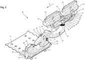
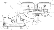
- pantograph is provided for each conductor strand, which by way of example in the Fig. 2 to 9 illustrated pantograph 10 is explained. Corresponding information also applies to the other pantographs.
- a support plate 11 is provided. This is struck by means of connecting screws 12, 12 'fixed to the inside of the downwardly projecting leg of the transport hanger 7.
- a fork-shaped support 16 rotatable about a rotation axis perpendicular to the support plate 11 is provided, on which a tilting arm 18 is rotatably arranged about a first rotation axis 17.
- the Kipparm 18 is a in FIGS. 2 to 5 in the prestressed state shown pressed coil spring 19 of the base 15 and thus pressed in the direction of the conductor strand 6.
- the coil spring 19 is arranged on an elongated projection of the bearing 16 and thus rotatable with the bearing 16 about the vertical axis of rotation on the support plate 11.
- a spiral spring other suitable elements can be used, which press the tilting arm 18 away from the base 15 and to the conductor strand 6.
- a mandrel 20 is provided which abuts against a arranged on the base 15 centering 21. This comes in particular to effect when the transport hanger 11 is removed with the pantograph 10 of the conductor rail 2 and then re-used.
- the centering mandrel 20 may preferably have a wedge-shaped or conical shape and engage in the corresponding internally wedge-shaped or internally tapered stop 21.
- the tilting arm 18 can advantageously be brought into a position running parallel to its travel direction F and to the longitudinal direction L of the conductor rail 2 in order to be able to introduce the current collector 10 cleanly into the conductor strand 6.
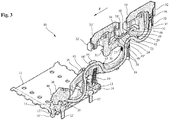
- FIGS. 2 to 5 Right end is inserted into a hollow cylindrical opening 22 of the rocker arm 18 is also a hollow cylindrical connector 23 of a bearing block 24.
- the connecting piece 23 is pressed by a further coil spring 25 to the conductor strand 6 and is secured by means of a latching connection 26 against falling out of the opening 22.
- the bearing block 22 yielding slightly in the direction of the conductor strand 6, whereby unevenness in the conductor strand 6 can be compensated.
- the rocker 29 On the bearing block 23 is rotatable about a second axis of rotation 27 a seen from the side substantially U-shaped rocker 29 with a connecting leg 30 is disposed at the ends of support legs 31, 31 ', each with a contact strip holder 32, 32' are arranged.
- the rocker 29 At least in the area between the support legs 31, 31 'and the bearing block 22, the rocker 29 has elongated recesses or hollows.
- Both the base 15 and the Kipparm 18, the bearing block 23 with the hollow cylindrical fitting 24 and the rocker 29 are made of plastic, in particular a hard plastic such. Hard plastic made.
- the rocker 29 and the Kipparm 18 are substantially movable in a running through the conductor strand 6 driving plane, apart from itself unwanted side movements, which may be caused by a non-exact course of the conductor strand, the conductor rail and the driving movement of the consumer.
- the driving plane is substantially perpendicular to a plane through the plurality of strands.
- the two sliding pieces 33, 33 ' are electrically conductively connected to each other via a connecting cable 34.
- a female connector 35 for a connector 36 is provided.
- the plug 36 is fixed to one end of a connection cable 37.
- the connection cable 37 is connected at its other, stripped end fixed to a terminal 38.
- the terminal 38 is connected via a designed as a dovetail connector 38 to the base 15. Via a further connection 40 of the connection terminal 38, a connecting line to one or more electrical consumers of the transport hanger 7 can then be produced.
- the connecting cable 37 is guided on its way from the socket 35 to the terminal 38 advantageously defined in a cable guide channel 41.
- the cable channel 41 in this case initially has an opening 42 in the bottom of the rocker 29, through which the cable 37 is inserted from the socket 34 coming between the two side walls of the rocker 29, in order then through the hollow cylindrical Connector 24 of the bearing block 23 to be performed. From there, the cable 37 is then guided through the front region of the tilting arm 18, which is preferably open on the underside. In this way, the cable 37 can be easily mounted, so that its free end can be guided around by a arranged adjacent to the bearing 16 opening 43 in the upper wall of the tilting arm 18 and then around two clamping legs 44, 44 'by clamping. Subsequently, the cable 37 is inserted through a further opening 45 in the shorter arm of the tilting arm 18 down and through a hollow cylindrical cable entry 46 into the base 15, where it is then still guided in the cable channel 40 to the terminal 38.
- a viewing window 47 in the longer part of the tilting arm 18 also allows from the side of a check whether the cable 37 is properly guided.
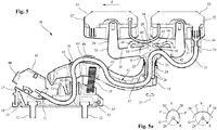
- rocker 29 In order to ensure that the contact strips 31, 31 'both bear on the conductor strand 6 as well as possible and uniformly, it can preferably be ensured that the rocker 29 automatically moves back into this rest position upon deflection from its rest position shown in the drawings.
- two symmetrically shaped spring arms 48, 48 ' are provided on the horizontal connecting leg of the rocker 29, which point in the direction of the bearing block 23.
- the spring arms 48, 48 ' have at their free ends thickened sliding contacts 49, 49', which can also slide on symmetrically designed sliding surfaces 50, 50 'of the bearing block 23.
- the sliding surfaces 50, 50 ' formed so that when moving the rocker 29 from the rest position that spring arm 48, 48', which is moved from its rest position away from the base 15 and to the conductor strand 6, is stretched while the other spring arm 48, 48 ', which is moved from its rest position to the base 15 and away from the conductor strand 6, is relaxed.
- the region of the sliding surfaces 50, 50 ' which extend from the rest position of the sliding contacts 49, 49' to the axis of symmetry S through the third axis of rotation 28, are steeper than an imaginary circle G with the radius R of the sliding contacts 49, 49 'about the axis of rotation 28.
- the other portion of the sliding surfaces 50, 50' may be less steep.
- This return mechanism is exemplary in Fig. 5a shown on the left.
- the sliding surfaces 50, 50 'as shown in detail of Fig. 5a be formed as a circular section with the radius R, which intersects with the imaginary circle G of the sliding contacts 49, 49 'in the rest position of the sliding contacts 49, 49' on the sliding surfaces 50, 50 'at the intersection P and P'.
- it is also possible to provide other configurations of the sliding surfaces which produce the same effect for example a straight sliding surface extending tangentially through the intersection P on the imaginary circle G.
- the spring arms 48, 48 'could also be provided on the bearing block 23, so that correspondingly sliding surfaces would be provided on the rocker 29, which upon a deflection of the rocker 29 from the inoperative position would stretch the spring arm which counteracts the deflection.
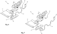
- Fig. 6 to 9 show again exploded views of in Fig. 2 to 5 illustrated in detail pantograph 10th
Landscapes
- Engineering & Computer Science (AREA)
- Power Engineering (AREA)
- Transportation (AREA)
- Mechanical Engineering (AREA)
- Current-Collector Devices For Electrically Propelled Vehicles (AREA)
Description
Die Erfindung betrifft einen Stromabnehmer für eine Schleifleitung nach dem Oberbegriff des Anspruchs 1 sowie ein Schleifleitungssystem nach dem Oberbegriff des Anspruchs 15.The invention relates to a current collector for a conductor rail according to the preamble of
Bei bekannten Schleifleitungssystemen fährt ein verfahrbarer elektrischer Verbraucher längs einer Schleifleitung. Die Versorgung des Verbrauchers mit elektrischer Energie erfolgt dabei über einen Stromabnehmer, dessen Schleifkontakte in Leiterstränge der Schleifleitung eingreifen. Der Verbraucher kann z.B. ein Transportgehänge einer Schienenhängebahn, ein auf Schienen verfahrbarer Leitungswagen oder auch sog. E-RTG-Containerkräne sein, welche mit einem elektrischen Fahrantrieb ausgerüstet sind, der von der Schleifleitung mit elektrischer Energie versorgt wird.In known conductor rail systems travels a movable electrical load along a conductor rail. The supply of the consumer with electrical energy is carried out via a current collector whose sliding contacts engage in conductor strands of the conductor rail. The consumer may e.g. a Transportgehänge a rail overhead railway, a movable on rails trolley or so-called. E-RTG container cranes, which are equipped with an electric traction drive, which is supplied by the conductor rail with electrical energy.
Die
Die
Die
Zudem wird dort die Bewegung des Schleifkontakts lediglich durch die beiden Endanschläge begrenzt. Eine automatische Rückstellung in eine bevorzugte Ruhestellung mit guter Anlage an den Leiterstrang der Schleifleitung wird allenfalls durch die willkürlich durch den Stromabnehmerkopf geführten Leitungen bereitgestellt.In addition, the movement of the sliding contact is limited only by the two end stops. An automatic return to a preferred rest position with good contact with the conductor strand of the conductor rail is provided at best by the arbitrarily guided through the current collector head lines.
Die
Bei der
Auch bei der
Die
Die
Die
Die
Aufgabe der Erfindung ist es deshalb, einen Stromabnehmer sowie ein Schleifleitungssystem bereitzustellen, welche die oben genannten Nachteile überwinden und eine sichere Führung des Stromabnehmerkontakts in dem Leiterstrang der Schleifleitung sowie eine zuverlässige Energieübertragung ermöglichen.The object of the invention is therefore to provide a current collector and a conductor rail system, which overcome the above-mentioned disadvantages and allow safe guidance of the pantograph contact in the conductor strand of the conductor rail and a reliable energy transfer.
Die Erfindung löst die Aufgabe durch einen Stromabnehmer mit den Merkmalen des Anspruchs 1 sowie ein Schleifleitungssystem mit den Merkmalen des Anspruchs 15. Vorteilhafte Weiterbildungen und Ausgestaltungen der Erfindung sind in den Unteransprüchen angegeben.The invention solves the problem by a current collector with the features of
Der eingangs genannte Stromabnehmer ist erfindungsgemäß dadurch gekennzeichnet, dass an der Wippe ein erster Federarm angeordnet ist, der auf einer dem Kipparm zugeordneten ersten Gleitfläche gleitet, oder der erste Federarm dem Kipparm zugeordnet und die erste Gleitfläche an der Wippe angeordnet ist, wobei der erste Federarm bei Auslenkung der Wippe aus einer Ruhestellung gespannt wird und die Wippe zur Ruhestellung hin drückt. Hierdurch kann sichergestellt werden, dass die beiden Schleifstücke der Wippe stets optimal und gleichmäßig an den Leiterstrang angedrückt werden. Ein Abheben der Schleifstücke, welches zu einer schlechteren Energieübertragung und ggf. auch zu unerwünschten Überschlägen zwischen Leiterstrang und Schleifstücken führt, kann somit weitgehend vermieden werden. Auch kann eine gleichmäßige Abnutzung der Schleifstücke erreicht werden, so dass Wartungsintervalle für den Austausch der Schleifstücke vergrößert und dadurch bedingte Stillstände der Anlage verringert werden können.The aforementioned pantograph according to the invention is characterized in that on the rocker a first spring arm is arranged, which slides on a Kipparm associated first sliding surface, or the first spring arm associated Kipparm and the first sliding surface is arranged on the rocker, wherein the first spring arm when the rocker is deflected out of a rest position, the rocker is pressed towards the rest position. This can ensure that the two contact pieces of the rocker are always pressed optimally and evenly to the conductor strand. A lifting of the sliding pieces, which leads to a poorer energy transfer and possibly also to unwanted flashovers between the conductor strand and grinding pieces, can thus be largely avoided. Also, a uniform wear of the grinding pieces can be achieved, so that maintenance intervals for the replacement of the grinding pieces increases and thereby conditional downtime of the system can be reduced.
In einer vorteilhaften Ausführung kann an der Wippe ein zweiter Federarm angeordnet sein, der auf einer dem Kipparm zugeordneten zweiten Gleitfläche gleitet, wobei der erste Federarm bei Auslenkung der Wippe aus der Ruhestellung in eine Drehrichtung um die Drehachse gespannt wird und die Wippe entgegen der Drehrichtung zur Ruhestellung hin drückt, und der zweite Federarm bei Auslenkung der Wippe aus der Ruhestellung in die andere Drehrichtung gespannt wird und die Wippe entgegen der anderen Drehrichtung zur Ruhestellung hin drückt. Alternativ kann auch der zweite Federarm dem Kipparm zugeordnet und die zweite Gleitfläche an der Wippe angeordnet sein, also die Anordnung von Federarm und Gleitfläche vertauscht werden.In an advantageous embodiment, a second spring arm can be arranged on the rocker, which slides on a Kipparm associated second sliding surface, wherein the first spring arm upon deflection of the rocker from the rest position in a rotational direction about the Is pivoted rotation axis and the rocker against the direction of rotation to the rest position pushes, and the second spring arm is stretched in deflection of the rocker from the rest position in the other direction and presses the rocker against the other direction of rotation to the rest position. Alternatively, the second spring arm associated with the Kipparm and the second sliding surface may be arranged on the rocker, so the arrangement of spring arm and sliding surface are reversed.
Bevorzugt können dabei die an der Wippe angeordneten Federarme auf einander in Fahrrichtung gegenüberliegenden Seiten der Drehachse angeordnet und aufeinander zu gerichtet sein. Die Federarme weisen als in Richtung der Drehachse oder einer durch diese reichende Symmetrieachse. Entsprechend können in einer alternativen Ausgestaltung die an dem Kipparm angeordneten Federarme von der Drehachse weg in entgegengesetzte Richtungen zeigen. Weiter können in einer vorteilhaften Fortbildung die Federarme und/oder die Gleitflächen symmetrisch zu einer senkrecht auf der Fahrrichtung stehenden und durch die Drehachse verlaufenden Symmetrieachse ausgebildet sein.In this case, the spring arms arranged on the rocker can preferably be arranged on mutually opposite sides of the axis of rotation in the travel direction and directed toward one another. The spring arms have as in the direction of the axis of rotation or a reaching through this axis of symmetry. Accordingly, in an alternative embodiment, arranged on the tilt arm spring arms can point away from the axis of rotation in opposite directions. Further, in an advantageous development, the spring arms and / or the sliding surfaces may be symmetrical to a symmetry axis perpendicular to the direction of travel and extending through the axis of rotation.
Bevorzugt können der oder die Federarme mit ihrem freien Ende auf der oder den Gleitflächen gleiten. Hierbei können der oder die Federarme an ihrem freien Ende verdickte Gleitkontakte aufweisen, um die Gleitfähigkeit zu verbessern.Preferably, the one or more spring arms can slide with its free end on the or the sliding surfaces. Here, the one or more spring arms may have thickened sliding contacts at their free end to improve the lubricity.
In einer konstruktiv günstigen Ausführung können die Federarme und/oder die Gleitflächen an einem Lagerblock des Kipparms angeordnet sein, welcher bevorzugt um eine senkrecht auf der Drehachse der Wippe und der Fahrrichtung stehenden weiteren Drehachse drehbar am Kipparm angeordnet ist. Dabei kann der Lagerblock vorteilhaft ein hohles, bevorzugt hohlzylindrisches Anschlussstück aufweisen, welches in eine entsprechende hohle, bevorzugt hohlzylindrische Öffnung des Kipparms eingesteckt ist. Zum Halten des Lagerblocks am Kipparm kann eine Rast- und/oder Schnappverbindung zwischen Anschlussstück und Öffnung des Kipparms vorgesehen werden.In a structurally favorable embodiment, the spring arms and / or the sliding surfaces can be arranged on a bearing block of the tilting arm, which is preferably arranged rotatably about a perpendicular to the axis of rotation of the rocker and the direction of travel standing further rotation axis on Kipparm. In this case, the bearing block may advantageously have a hollow, preferably hollow cylindrical connecting piece, which is inserted into a corresponding hollow, preferably hollow cylindrical opening of the tilting arm. For holding the bearing block on Kipparm can be provided a detent and / or snap connection between the connecting piece and the opening of the Kipparms.
Bevorzugt kann der Kipparm um eine weitere senkrecht zur Fahrrichtung und parallel zur Drehachse der Wippe verlaufenden Drehachse drehbar an einer Basis angeordnet sein, wobei vorteilhaft der Kipparm durch eine Feder von der Basis weg und zu dem Leiterstrang hin gedrückt werden kann. Hierdurch können die Wippe und die Schleifstücke sicher an den Leiterstrang gedrückt werden. Der Kipparm kann zusätzlich noch um eine weitere, senkrecht auf der Fahrrichtung und senkrecht auf der Drehachse der Wippe stehende Drehachse, also eine senkrecht auf einer durch die Leiterstränge definierten Ebene, stehen. Hierdurch kann die Wippe seitliche Abweichungen von der Fahrrichtung ausgleichen.Preferably, the Kipparm can be arranged rotatably on a base about a further perpendicular to the direction of travel and parallel to the axis of rotation of the rocker rotation axis, wherein advantageously the Kipparm can be pressed by a spring away from the base and to the conductor strand. As a result, the rocker and the sliding pieces can be pressed securely against the conductor strand. In addition, the tilting arm can be further rotated about an axis of rotation perpendicular to the direction of travel and perpendicular to the axis of rotation of the rocker, that is one perpendicular to a plane defined by the conductor strands, stand. As a result, the rocker can compensate for lateral deviations from the direction of travel.
In einer montagetechnisch günstigen Ausgestaltung kann die Basis mittels einer oder mehrerer Schnappverbindungen an einer Tragplatte anklippsbar sein. Hierdurch kann ein schneller und einfacher Austausch des Stromabnehmers erfolgen, beispielsweise bei einem defekt des Stromabnehmers oder abgenutzten Schleifstücken. Vorteilhaft kann auch eine Anschlussklemme für das schleifstückferne Ende einer Anschlussleitung für die Schleifstücke lösbar mit der Basis verbunden sein, bevorzugt mittels einer schwalbenschwanzähnlich ausgebildeten Steckverbindung zwischen Anschlussklemme und BasisIn a montagetechnisch favorable embodiment, the base can be anklippsbar by means of one or more snap connections on a support plate. This allows a quick and easy replacement of the pantograph done, for example, in a defect of the pantograph or worn contact pieces. Advantageously, a connection terminal for the end remote from the grinding end of a connection line for the contact strips can also be detachably connected to the base, preferably by means of a dovetail-like connector between the connection terminal and the base
Vorteilhaft können die Basis als auch der Kipparm, der Lagerblock, das hohlzylindrische Anschlussstück und/oder die Wippe aus Kunststoff, insbesondere einem harten Kunststoff wie z.B. Hartplastik hergestellt. Bevorzugt können die Federarme aus dem gleichen Material wie die Wippe bzw. der Lagerblock hergestellt sein, und besonders bevorzugt einstückig mit der Wippe bzw. dem Lagerblock.Advantageously, the base and the Kipparm, the bearing block, the hollow cylindrical connector and / or the rocker made of plastic, in particular a hard plastic such. Hard plastic made. Preferably, the spring arms can be made of the same material as the rocker or the bearing block, and particularly preferably in one piece with the rocker or the bearing block.
Dabei kann der der oder die Federarme an einem Verbindungsschenkel der Wippe vorgesehen sein, insbesondere an bezüglich der senkecht zur Fahrrichtung verlaufenden Drehachse gegenüberliegenden Seiten der Wippe.Here, the one or more spring arms may be provided on a connecting leg of the rocker, in particular with respect to the senkecht to the direction of travel extending axis of rotation opposite sides of the rocker.
Bevorzugt kann zumindest die erste Gleitfläche so ausgebildet sein, dass der erste Federarm beim Bewegen aus der Ruhestellung stärker gespannt ist als in der Ruhestellung. Hierbei kann der erste Federarm in der Ruhestellung die Gleitfläche berühren, wobei ein sich daran anschließender Bereich der Gleitfläche so ausgebildet ist, dass der erste Federarm beim Bewegen aus der Ruhestellung in eine Richtung stärker gespannt ist als in der Ruhestellung. Vorteilhaft kann dabei ein sich an den Bereich der Gleitfläche anschließender weiterer Bereich der Gleitfläche, der sich bezüglich der Stelle, an der der erste Federarm die Gleitfläche berührt, auf der entgegengesetzten Seite wie der Bereich der Gleitfläche liegt, so ausgebildet sein, dass der erste Federarm beim Bewegen aus der Ruhestellung in die entgegengesetzte Richtung stärker gespannt ist als in der Ruhestellung. Hierdurch kann bei der Bewegung der Wippe in beiden Richtungen selbst mittels nur eines Federarms eine Rückstellung der Wippe in die Ruhestellung erreicht werden. Alternativ kann der sich an den Bereich der Gleitfläche anschließende weitere Bereich so ausgebildet sein, dass der erste Federarm beim Bewegen aus der Ruhestellung in die entgegengesetzte Richtung schwächer gespannt ist als in der Ruhestellung.Preferably, at least the first sliding surface may be formed so that the first spring arm is stretched when moving from the rest position stronger than in the rest position. Here, the first spring arm in the rest position touching the sliding surface, wherein a subsequent region of the sliding surface is formed so that the first spring arm when moving from the rest position is stretched in one direction stronger than in the rest position. Advantageously, a further region of the sliding surface which adjoins the region of the sliding surface and which, with respect to the point at which the first spring arm contacts the sliding surface, lies on the opposite side as the region of the sliding surface, may be designed such that the first spring arm when moving from the rest position in the opposite direction is more stretched than in the rest position. This can be achieved in the rest position in the movement of the rocker in both directions even by means of only one spring arm a provision of the rocker. Alternatively, the further region adjoining the region of the sliding surface may be formed such that the first Spring arm when moving from the rest position in the opposite direction is weaker tension than in the rest position.
Durch ein mit einem solchen Stromabnehmer ausgerüstetes Schleifleitungssystem können diese Vorteile gut ausgenutzt werden. Dabei kann vorteilhaft der verfahrbare elektrische Verbraucher mehrere nebeneinander angeordnete Stromabnehmer zur Kontaktierung mit entsprechend nebeneinander angeordneten Leitersträngen der Schleifleitung aufweisen.By equipped with such a pantograph conductor rail system, these advantages can be well utilized. In this case, advantageously, the movable electrical load having a plurality of juxtaposed pantograph for contacting with appropriately juxtaposed conductor strands of the conductor rail.
Die Erfindung wird nachfolgend anhand von detaillierten Ausführungsbeispielen mit Bezug auf die begleitenden Zeichnungen beschrieben. Diese zeigen:
- Fig. 1
- eine schematische, dreidimensionale Ansicht eines Abschnitts eines erfindungsgemäßen Schleifleitungssystems;
- Fig. 2
- eine schematische, dreidimensionale Ansicht eines erfindungsgemäßen Stromabnehmer des Schleifleitungssystems aus
Fig. 1 ; - Fig. 3
- eine Schnittansicht durch Stromabnehmer aus
Fig. 2 ; - Fig. 4
- eine seitliche Draufsicht auf den Stromabnehmer gemäß
Fig. 2 ; - Fig. 5
- eine seitliche Schnittansicht auf den Stromabnehmer gemäß
Fig. 3 ; - Fig. 5a
- schematische Detailansichten des Rückstellmechanismus aus
Fig. 5 ; - Fig. 6-9
- Explosionsdarstellungen des Stromabnehmers aus
Fig. 3 .
- Fig. 1
- a schematic, three-dimensional view of a portion of a conductor rail system according to the invention;
- Fig. 2
- a schematic, three-dimensional view of a current collector according to the invention of the conductor rail system
Fig. 1 ; - Fig. 3
- a sectional view through current collector
Fig. 2 ; - Fig. 4
- a lateral plan view of the pantograph according to
Fig. 2 ; - Fig. 5
- a side sectional view of the pantograph according to
Fig. 3 ; - Fig. 5a
- schematic detail views of the return mechanism
Fig. 5 ; - Fig. 6-9
- Exploded views of the pantograph
Fig. 3 ,
Das in
Die Leiterstranghalterung 4 hält insgesamt sechs längs der Schleifleitung 2 in eine Längsrichtung L verlaufende längliche Isolierprofile, die nachfolgend anhand von Isolierprofil 5 beschrieben werden. Die Angaben hierzu gelten entsprechend auch für die weiteren Isolierprofile.The
In das im wesentlichen U-förmige elektrisch nicht leitende Isolierprofil 5 ist ein elektrisch leitender Leiterstrang 6 eingesetzt, der im Wesentlichen C- oder U-förmigen Querschnitt aufweist. Die offene Seite des U-förmigen Querschnitts von Isolierprofil 5 und Leiterstrang 6 zeigen in
Das in eine Fahrrichtung F, welche in Längsrichtung L verläuft, verfahrbare Transportgehänge 7 weist einen in
Zur Versorgung der elektrischen Verbraucher des Transportgehänges 7, beispielsweise des Antriebsmotors, und auch zur Verbindung der elektrischen Verbraucher mit dem Erd- und/oder Schutzleiterstrang ist für jeden Leiterstrang mindestens ein Stromabnehmer vorgesehen, welcher exemplarisch anhand eines in den
Um den Stromabnehmer 10 an dem Transportgehänge 7 zu befestigen, ist eine Tragplatte 11 vorgesehen. Diese wird mittels Verbindungsschrauben 12, 12' fest an der Innenseite des nach unten auskragenden Schenkel des Transportgehänges 7 angeschlagen. An einander gegenüberliegenden, treppenförmig gebogenen Seitenkanten der Tragplatte 11 sind mehrere Rücksprünge 13, 13' paarweise einander gegenüberliegend angeordnet. In diese Rücksprünge 13, 13' werden Schnappverbindungen 14, 14' einer Basis 15 des Stromabnehmers aufgeklipst. Wie in
An der Basis 15 ist eine um eine senkrecht auf der Tragplatte 11 stehende Drehachse drehbare gabelförmige Lagerung 16 vorgesehen, an welcher um eine erste Drehachse 17 drehbar ein Kipparm 18 angeordnet ist. Der Kipparm 18 wird über eine in
Um zu verhindern, dass der Kipparm 18 zu weit in Richtung Leiterstrang 6 bewegt wird, ist am kürzeren, in
Am längeren, in
Am Lagerblock 23 ist um eine zweite Drehachse 27 drehbar eine von der Seite aus gesehen im Wesentlichen U-förmige Wippe 29 mit einem Verbindungsschenkel 30 angeordnet, an dessen Enden Tragschenkel 31, 31' mit jeweils einem Schleifstückhalter 32, 32' angeordnet sind. Die Schleifstückhalter 32, 32' tragen jeweils ein Schleifstück 33, 33', welche zur schleifenden Kontaktierung des Leiterstrangs 6 vorgesehen sind. Zumindest im Bereich zwischen den Tragschenkeln 31, 31' und dem Lagerblock 22 weist die Wippe 29 längliche Ausnehmungen oder Mulden auf.On the
Sowohl die Basis 15 als auch der Kipparm 18, der Lagerblock 23 mit dem hohlzylindrischen Anschlussstück 24 und die Wippe 29 sind dabei aus Kunststoff, insbesondere einem harten Kunststoff wie z.B. Hartplastik hergestellt.Both the
Um die Schleifstücke 33, 33' in den U-förmigen Leiterstrang 6 einführen und längs diesem in Fahrrichtung F verfahren zu können, sind die Wippe 29 und der Kipparm 18 dabei im wesentlichen in einer durch den Leiterstrang 6 verlaufenden Fahrebene bewegbar, abgesehen von an sich nicht erwünschten Seitenbewegungen, welche durch eine nicht exakten Verlauf des Leiterstrangs, der Schleifleitung und der Fahrbewegung des Verbrauchers verursacht sein können. Die Fahrebene steht dabei im wesentlichen senkrecht auf einer Ebene durch die mehreren Leitestränge.In order to introduce the sliding
Um den vom Leiterstrang 6 abgegriffenen elektrischen Strom zu den elektrischen Verbrauchern auf dem Transportgehänge 7 zu leiten, sind die beiden Schleifstücke 33, 33' über ein Verbindungskabel 34 elektrisch leitend miteinander verbunden. Weiter ist am in
Das Anschlusskabel 37 ist dabei auf seinem Weg von der Steckerbuchse 35 zur Anschlussklemme 38 vorteilhaft in einem Kabelführungskanal 41 definiert geführt. Durch diese definierte Führung des Kabels 37 können ansonst nachteilige Beeinflussungen der Beweglichkeit des Kipparms 18 bzw. der Wippe 29 weitgehend vermieden werden.The connecting
Der Kabelkanal 41 weist dabei zunächst einen Durchbruch 42 in der Unterseite der Wippe 29 auf, durch den das Kabel 37 von der Steckerbuchse 34 kommend zwischen die beiden Seitenwandungen der Wippe 29 eingeführt wird, um dann durch das hohlzylindrische Anschlussstück 24 des Lagerblocks 23 geführt zu werden. Von dort wird das Kabel 37 dann durch den vorderen Bereich des Kipparms 18 geführt, welcher bevorzugt auf der Unterseite offen ist. Hierdurch kann das Kabel 37 leicht montiert werden, so dass sein freies Ende durch einen benachbart des Lagers 16 angeordneten Durchbruch 43 in der oberen Wandung des Kipparms 18 und dann um zwei Klemmschenkel 44, 44' klemmend herumgeführt werden kann. Daran anschließend wird das Kabel 37 durch einen weiteren Durchbruch 45 im kürzeren Arm des Kipparms 18 nach unten und durch einen hohlzylindrischen Kabeleingang 46 in die Basis 15 eingeführt, wo es dann immer noch im Kabelkanal 40 zur Anschlussklemme 38 geführt wird.The
Ein Sichtfenster 47 im längeren Teil des Kipparms 18 ermöglicht auch von der Seite aus eine Kontrolle, ob das Kabel 37 ordnungsgemäß geführt ist.A
Um sicherzustellen, dass die Schleifstücke 31, 31' beide möglichst gut und gleichmäßig an dem Leiterstrang 6 anliegen, kann bevorzugt sichergestellt werden, dass sich die Wippe 29 bei Auslenkung aus ihrer in den Zeichnungen gezeigten Ruhestellung selbständig wieder in diese Ruhestellung zurückbewegt. Hierfür sind an dem waagrechten Verbindungsschenkel der Wippe 29 zwei symmetrisch ausgebildete Federarme 48, 48' vorgesehen, die in Richtung des Lagerblocks 23 zeigen. Die Federarme 48, 48' weisen an ihren freien Enden verdickte Gleitkontakte 49, 49' auf, welche auf ebenfalls symmetrisch ausgebildeten Gleitflächen 50, 50' des Lagerblocks 23 gleiten können.In order to ensure that the contact strips 31, 31 'both bear on the conductor strand 6 as well as possible and uniformly, it can preferably be ensured that the
Da die Federarme 48, 48' standardmäßig gegen die Gleitflächen 50, 50' vorgespannt sind, wird hierdurch beständig eine Rückstellkraft ausgeübt, welche die Wippe 29 in die in den Figuren gezeigte Ruhestellung bewegt. Dies ist in den Zeichnungen dadurch dargestellt, dass die Gleitkontakte 49, 49' vermeintlich in die Gleitflächen 50, 50' eindringen. Tatsächlich gleiten die Gleitkontakte 49, 49' jedoch auf den Gleitflächen 50, 50', ohne in diese einzudringen.Since the
Wird die Wippe 29 aus dieser Ruhestellung ausgelenkt, so erhöht sich die Rückstellkraft desjenigen Federarms 48, 48', der mit der Wippe 29 von der Basis 15 weg und zu dem Leiterstrang 6 hin bewegt wird. Die Rückstellkraft des jeweils anderen Federarms 48, 48' hingegen verringert sich, so dass die Wippe 29 wieder in die Ruhestellung zurückbewegt wird. Wird die Wippe 29 beispielsweise auf der in
Hierzu sind die Gleitflächen 50, 50' so ausgebildet, dass beim Bewegen der Wippe 29 aus der Ruhestellung derjenige Federarm 48, 48', der aus seiner Ruhestellung von der Basis 15 weg und zu dem Leiterstrang 6 hin bewegt wird, stärker gespannt wird, während der andere Federarm 48, 48', der aus seiner Ruhestellung zu der Basis 15 hin und von dem Leiterstrang 6 weg bewegt wird, entspannt wird.For this purpose, the sliding
In einer vorteilhaften Ausführung können hierzu die Bereich der Gleitflächen 50, 50', die von der Ruhestellung der Gleitkontakte 49, 49' zu der Symmetrieachse S durch die dritte Drehachse 28 hin verlaufen, steiler verlaufen als ein gedachter Kreis G mit dem Radius R der Gleitkontakte 49, 49' um die Drehachse 28. Gleichermaßen können die anderen Bereich der Gleitflächen 50, 50' weniger steil verlaufen. Dieser Rückstellmechanismus ist beispielhaft in
Beispielsweise können die Gleitflächen 50, 50' wie im Detail von
Auch kann der Bereich der Gleitflächen 50, 50', die von der Ruhestellung der Gleitkontakte 49, 49' von der Symmetrieachse S weg verlaufen, flacher verlaufen als der gedachte Kreis G der Gleitkontakte 49, 49'. Hierdurch würde bei Auslenkung der Wippe 29 aus der Ruhestellung derjenige Federarm 48, 48', der vom Leiterstrang 6 weg und zur Basis 15 hin bewegt wird, stärker gespannt werden als in seiner Ruhestellung, so dass er die Wippe 29 wieder in die Ruhestellung zurückzieht. Dieser Rückstellmechanismus ist beispielhaft in
Werden die in
Grundsätzlich könnten die Federarme 48, 48' auch an dem Lagerblock 23 vorgesehen werden, so dass an der Wippe 29 entsprechend Gleitflächen vorzusehen werden, die bei einer Auslenkung der Wippe 29 aus der Ruhestellung denjenigen Federarm stärker spannen, der der Auslenkung entgegenwirkt.In principle, the
Die weiteren
- 11
- SchleifleitungssystemConductor Rail
- 22
- Schleifleitungcontact line
- 33
- Schienenstrangrail track
- 44
- LeiterstranghalterungConductor strand mount
- 55
- Isolierprofilinsulating profile
- 66
- Leiterstrangconductor lane
- 77
- Transportgehängetransport gear
- 88th
- Antriebsräderdrive wheels
- 99
- SeitenführungsräderSide guide wheels
- 1010
- Stromabnehmerpantograph
- 1111
- Tragplattesupport plate
- 12, 12'12, 12 '
- Verbindungsschraubenconnecting bolts
- 13, 13'13, 13 '
- Rücksprüngerecesses
- 14, 14'14, 14 '
- Schnappverbindungensnap connections
- 1515
- BasisBase
- 1616
- gabelförmige Lagerungforked storage
- 1717
- erste Drehachse des Kipparms gegenüber der Basisfirst axis of rotation of the tipping arm opposite the base
- 1818
- Kipparmrocker arm
- 1919
- Spiralfederspiral spring
- 2020
- Zentrierdorncentering
- 2121
- ZentrieranschlagCentering stop
- 2222
- hohlzylindrische Öffnunghollow cylindrical opening
- 2323
- Lagerblockbearing block
- 2424
- hohlzylindrisches Anschlussstückhollow cylindrical connector
- 2525
- Spiralfederspiral spring
- 2626
- Rastverbindunglocking connection
- 2727
- zweite Drehachse des Lagerblocks gegenüber dem Kipparmsecond axis of rotation of the bearing block opposite the Kipparm
- 2828
- dritte Drehachse der Wippe gegenüber dem Lagerblockthird axis of rotation of the rocker relative to the bearing block
- 2929
- Wippeseesaw
- 3030
- Verbindungsschenkelconnecting leg
- 31, 31'31, 31 '
- Tragschenkelsupporting leg
- 32, 32'32, 32 '
- SchleifstückhalterGrinding holder
- 33, 33'33, 33 '
- SchleifstückeContact strips
- 3434
- Verbindungskabelconnection cable
- 3535
- Steckerbuchsesocket
- 3636
- Steckerplug
- 3737
- Anschlusskabelconnection cable
- 3838
- Anschlussklemmeterminal
- 3939
- Steckverbindung (Schwalbenschwanz)Plug connection (dovetail)
- 4040
- Anschluss elektrische VerbraucherConnection of electrical consumers
- 4141
- KabelführungskanalCable channel
- 4242
- Durchbruch WippeBreakthrough seesaw
- 4343
- Durchbruch KipparmBreakthrough Kipparm
- 44, 44'44, 44 '
- Klemmschenkelclamping leg
- 4545
- weiterer Durchbruch Kipparmanother breakthrough Kipparm
- 4646
- Kabeleingang BasisCable entry base
- 4747
- Sichtfensterwindow
- 48, 48'48, 48 '
- Federarmespring arms
- 49, 49'49, 49 '
- Gleitkontaktesliding contacts
- 50, 50'50, 50 '
- Gleitflächensliding surfaces
- LL
- Längsrichtung SchleifleitungLongitudinal conductor line
- FF
- Fahrrichtung StromabnehmerDriving direction pantograph
- GG
- gedachter Kreis der Gleitkontakte um die dritte Drehachseimaginary circle of the sliding contacts around the third axis of rotation
- P, P'P, P '
- Schnittpunkt Gleitflächen mit gedachtem Kreis der GleitkontakteIntersection of sliding surfaces with a conceived circle of the sliding contacts
- RR
- Radius Kreisabschnitt der GleitflächenRadius Circular section of the sliding surfaces
- SS
- Symmetrieachse der GleitflächenSymmetry axis of the sliding surfaces
Claims (15)
- Current collector (10) for an electrical consuming device which is movable in a direction of travel (F) along a conductor line (2) and having at least two pantograph slippers (33, 33') arranged one behind another in direction of travel (F) on a rocker (29), wherein the rocker (29) is mounted on a rocker arm (18) about a rotational axis (28) running perpendicularly to the direction of travel (F), by means of which rocker arm (18) the rocker (29) is movable for contacting the pantograph slippers (33, 33') with an electrically conductive conductor strand (6) of the conductor line (2) towards the conductor strand (6), characterised in that a first spring arm (48), which slides on a first sliding surface (50) assigned to the rocker arm (18), is arranged on the rocker (29), or the first spring arm (48) is assigned to the rocker arm (18) and the first sliding surface (50) is arranged on the rocker (29), wherein the first spring arm (48) on deflection of the rocker (29) is stretched from a rest position and presses the rocker (29) towards the rest position.
- Current collector (10) according to claim 1, characterised in that a second spring arm (48'), which slides on a second sliding surface (50') assigned to the rocker arm (18), is arranged on the rocker (29), or the second spring arm (48') is assigned to the rocker arm (18) and the second sliding surface (50') is arranged on the rocker (29), wherein the first spring arm (48) on deflection of the rocker (29) is stretched from the rest position in a direction of rotation about the rotational axis (28) and presses the rocker (29) towards the rest position counter to the direction of rotation, and the second spring arm (48') on deflection of the rocker (29) is stretched from the rest position in the other direction of rotation and presses the rocker (29) towards the rest position counter to the other direction of rotation.
- Current collector (10) according to claim 2, characterised in that the spring arms (48, 48') arranged on the rocker (29) are arranged on sides of the rotational axis (28) opposite one another in direction of travel (F) and are directed towards one another.
- Current collector (10) according to one of claims 2 to 3, characterised in that the spring arms (48, 48') and/or the sliding surfaces (50, 50') are designed to be symmetrical to an axis of symmetry (S) standing perpendicularly on the direction of travel (F) and running through the rotational axis (28).
- Current collector (10) according to one of the preceding claims, characterised in that the spring arm or the spring arms (48, 48') have widened sliding contacts (49, 49') at their free end.
- Current collector (10) according to one of the preceding claims, characterised in that the spring arms (48, 48') and/or the sliding surfaces (50, 50') are arranged on a bearing block (23) of the rocker arm (18).
- Current collector (10) according to claim 6, characterised in that the bearing block (23) is arranged to be rotatable on the rocker arm (18) about a further rotational axis (28) standing perpendicularly on the rotational axis (28) of the rocker (29) and the direction of travel (F).
- Current collector (10) according to one of claims 6 or 7, characterised in that the bearing block (23) has a hollow-cylindrical connecting piece (24) which is inserted into a corresponding hollow-cylindrical opening (22) of the rocker arm (18).
- Current collector (10) according to one of the preceding claims, characterised in that the rocker arm (18) is arranged to be rotatable on a base (15) about a further rotational axis (17) running perpendicularly to the direction of travel (F) and parallel to the rotational axis (28) of the rocker (29), wherein the rocker arm (18) is pressed away from the base (15) and towards the conductor strand (6) by a spring (19).
- Current collector (10) according to claim 9, characterised in that the base (15) can be clipped onto a support plate (11) by means of snap connections (14, 14').
- Current collector (10) according to one of the preceding claims, characterised in that the spring arm or the spring arms (48, 48') are produced in one piece with the rocker (29) or the bearing block (23).
- Current collector (10) according to one of the preceding claims, characterised in that the spring arm or the spring arms (48, 48') are provided on a connecting limb (30) of the rocker (29).
- Current collector (10) according to one of the preceding claims, characterised in that at least the first sliding surface (50) is designed so that the first spring arm (48) is stretched to a greater extent during movement from the rest position than in the rest position.
- Current collector (10) according to claim 13, characterised in that the first spring arm (48) in the rest position touches the sliding surface (50), and a region of the sliding surface (50) following on from that is designed so that the first spring arm (48) is stretched to a greater extent in one direction during movement from the rest position than in the rest position.
- Conductor line system (1) with a conductor line (2) and at least one electrical consumer which is movable on the conductor line (2) in its longitudinal direction, wherein the conductor line (2) has at least one electrically conductive conductor strand (6) for sliding contact with at least two pantograph slippers (33, 33') of a current collector (10), characterised in that the current collector (10) is designed according to one of claims 1 to 14.
Applications Claiming Priority (2)
| Application Number | Priority Date | Filing Date | Title |
|---|---|---|---|
| DE102015101849.7A DE102015101849A1 (en) | 2015-02-10 | 2015-02-10 | Pantograph and conductor rail system |
| PCT/EP2015/074567 WO2016128076A1 (en) | 2015-02-10 | 2015-10-23 | Current collector and conductor line system |
Publications (2)
| Publication Number | Publication Date |
|---|---|
| EP3083322A1 EP3083322A1 (en) | 2016-10-26 |
| EP3083322B1 true EP3083322B1 (en) | 2019-04-24 |
Family
ID=54347538
Family Applications (1)
| Application Number | Title | Priority Date | Filing Date |
|---|---|---|---|
| EP15784682.5A Active EP3083322B1 (en) | 2015-02-10 | 2015-10-23 | Current collector and conductor line system |
Country Status (4)
| Country | Link |
|---|---|
| US (1) | US10525830B2 (en) |
| EP (1) | EP3083322B1 (en) |
| DE (1) | DE102015101849A1 (en) |
| WO (1) | WO2016128076A1 (en) |
Cited By (1)
| Publication number | Priority date | Publication date | Assignee | Title |
|---|---|---|---|---|
| US20240006835A1 (en) * | 2022-01-18 | 2024-01-04 | Caterpillar Global Mining Equipment Llc | Slidable current collector and method for contacting conductor rail |
Families Citing this family (12)
| Publication number | Priority date | Publication date | Assignee | Title |
|---|---|---|---|---|
| DE102014107468A1 (en) * | 2014-05-27 | 2015-12-03 | Conductix-Wampfler Gmbh | Conductor line, pantograph and conductor rail system |
| DE102015101849A1 (en) * | 2015-02-10 | 2016-08-11 | Conductix-Wampfler Gmbh | Pantograph and conductor rail system |
| DE202017107220U1 (en) | 2017-11-28 | 2019-03-01 | Conductix-Wampfler Gmbh | Pantograph and conductor rail system |
| DE102017128173A1 (en) | 2017-11-28 | 2019-05-29 | Conductix-Wampfler Gmbh | Pantograph and conductor rail system |
| CN110194060B (en) * | 2018-02-27 | 2021-04-20 | 比亚迪股份有限公司 | Current collector and electric locomotive with same |
| CN110803040B (en) * | 2018-08-01 | 2022-03-18 | 比亚迪股份有限公司 | Charging knife assembly, rail vehicle with same and rail vehicle traffic system |
| DE102020123266A1 (en) | 2020-09-07 | 2022-03-10 | Conductix-Wampfler Gmbh | pantograph |
| DE202020105139U1 (en) | 2020-09-07 | 2021-12-08 | Conductix-Wampfler Gmbh | pantograph |
| DE102022103679A1 (en) | 2022-02-16 | 2023-08-17 | Conductix-Wampfler Gmbh | Current collector and conductor rail system |
| DE202022100889U1 (en) | 2022-02-16 | 2023-06-14 | Conductix-Wampfler Gmbh | Current collector and conductor rail system |
| DE102024119386A1 (en) * | 2024-07-08 | 2026-01-08 | DETO Holding GmbH | Current collector unit with sensor system |
| DE102024119384A1 (en) * | 2024-07-08 | 2026-01-08 | DETO Holding GmbH | Current collector system for drawing current from a conductor rail |
Family Cites Families (17)
| Publication number | Priority date | Publication date | Assignee | Title |
|---|---|---|---|---|
| US1826854A (en) * | 1930-03-13 | 1931-10-13 | Charles L Wilmot | Trolley |
| US3396246A (en) * | 1968-01-02 | 1968-08-06 | Rucker Mfg Company | Tandem collector assembly for overhead electrification system |
| FR2320204A1 (en) * | 1975-08-07 | 1977-03-04 | Gennevilliers Acieries | Electrical pickup for overhead cables - has overhead arm with two conducting shoes fixed about different axes to balance arm connected by rubber bush to mounting on overhead arm |
| DE3018428A1 (en) | 1980-05-14 | 1981-11-19 | Translift AG, 6010 Kriens, Luzern | CONTROL CURRENT TRANSFORMER IN THE FORM OF A CONTACTOR ARRANGEMENT FOR TRAVELING GEARBOXES IN CONVEYOR SYSTEMS |
| US4464546A (en) * | 1981-11-23 | 1984-08-07 | Westinghouse Electric Corp. | Power collection apparatus for a vehicle |
| FR2600287B2 (en) | 1985-11-20 | 1988-10-21 | Delachaux Sa | TROLLEYBUS HEAD |
| DE3610455A1 (en) | 1986-03-27 | 1987-10-01 | Vahle Paul Kg | Pivotable rocker arm current collector |
| JPS63202202A (en) | 1987-02-13 | 1988-08-22 | Matsushita Electric Works Ltd | Insulated trolley wire current collector |
| DE9004828U1 (en) | 1990-04-27 | 1991-08-29 | Wampfler Gmbh, 7858 Weil | Pantograph |
| JPH04193003A (en) * | 1990-11-27 | 1992-07-13 | H S S T:Kk | Current connector for traveling body |
| DE19540914C2 (en) | 1995-11-03 | 2000-11-16 | Deutsch Zentr Luft & Raumfahrt | Pantographs for the transmission of energy between a contact wire and a railcar |
| DE19541600C1 (en) * | 1995-11-08 | 1997-07-17 | Deutsche Forsch Luft Raumfahrt | Pantographs for the transmission of energy between a contact wire and a railcar |
| US6152273A (en) * | 1998-02-20 | 2000-11-28 | Magnetek, Inc. | Universal arm and mounting block for a current collector |
| DE20205710U1 (en) | 2002-04-11 | 2002-08-14 | Fahrleitungsbau GmbH, 45329 Essen | pantograph |
| DE102011076620A1 (en) * | 2011-05-27 | 2012-11-29 | Siemens Aktiengesellschaft | Non-rail vehicle |
| DE102015101849A1 (en) * | 2015-02-10 | 2016-08-11 | Conductix-Wampfler Gmbh | Pantograph and conductor rail system |
| DE102015101848B4 (en) * | 2015-02-10 | 2021-02-11 | Conductix-Wampfler Gmbh | Pantograph and conductor rail system |
-
2015
- 2015-02-10 DE DE102015101849.7A patent/DE102015101849A1/en not_active Withdrawn
- 2015-10-23 US US15/307,840 patent/US10525830B2/en active Active
- 2015-10-23 EP EP15784682.5A patent/EP3083322B1/en active Active
- 2015-10-23 WO PCT/EP2015/074567 patent/WO2016128076A1/en not_active Ceased
Non-Patent Citations (1)
| Title |
|---|
| None * |
Cited By (1)
| Publication number | Priority date | Publication date | Assignee | Title |
|---|---|---|---|---|
| US20240006835A1 (en) * | 2022-01-18 | 2024-01-04 | Caterpillar Global Mining Equipment Llc | Slidable current collector and method for contacting conductor rail |
Also Published As
| Publication number | Publication date |
|---|---|
| DE102015101849A1 (en) | 2016-08-11 |
| US10525830B2 (en) | 2020-01-07 |
| US20170057359A1 (en) | 2017-03-02 |
| EP3083322A1 (en) | 2016-10-26 |
| WO2016128076A1 (en) | 2016-08-18 |
Similar Documents
| Publication | Publication Date | Title |
|---|---|---|
| EP3083322B1 (en) | Current collector and conductor line system | |
| EP3359412B1 (en) | Rapid charging system and method for electrical connection of a vehicle to a charging station | |
| DE102015101848B4 (en) | Pantograph and conductor rail system | |
| EP3031104B1 (en) | Rapid charging system and method for mounting a contact apparatus on a bearing apparatus | |
| EP2324542B2 (en) | Conductor line, collector and conductor system | |
| EP3084940B9 (en) | Linear transport system and method for operating the linear transport system | |
| EP2969637B1 (en) | Conductor line, current collector, and conductor line system with a slotted waveguide for receiving an antenna | |
| EP2964481B2 (en) | Conductor line, current collector, and conductor line system | |
| EP3160816B1 (en) | Cable car system | |
| EP3765325B1 (en) | Fast charging system and method for electrically connecting a vehicle to a charging station | |
| EP3386832B1 (en) | Vehicle, in particular rail vehicle | |
| EP2683570A2 (en) | Mounting for a data conductor, energy transmission system and data transmission system | |
| DE102017128173A1 (en) | Pantograph and conductor rail system | |
| EP2958768B1 (en) | Contact device for contacting a contact conductor arrangement | |
| DE202015100622U1 (en) | Pantograph and conductor rail system | |
| DE19917309A1 (en) | Current pick up assembly for e.g. traveling bridge crane | |
| DE202015100623U1 (en) | Pantograph and conductor rail system | |
| WO2021018909A1 (en) | Distribution station and method for operating a distribution station for the automated production of a wiring harness | |
| DE4008196A1 (en) | Rail type conveyor for workpieces - has inward facing current rails on each drive rail, coacting with pick=ups | |
| DE202017107220U1 (en) | Pantograph and conductor rail system | |
| DE202008011700U1 (en) | Conductor line, pantograph and conductor rail system | |
| DE102023131552A1 (en) | Connecting element, conductor rail, current collector trolley and conductor rail system | |
| DE60209136T2 (en) | CONNECTION FOR W LANGUAGES | |
| DE202014102489U1 (en) | Conductor line, pantograph and conductor rail system |
Legal Events
| Date | Code | Title | Description |
|---|---|---|---|
| PUAI | Public reference made under article 153(3) epc to a published international application that has entered the european phase |
Free format text: ORIGINAL CODE: 0009012 |
|
| 17P | Request for examination filed |
Effective date: 20160427 |
|
| AK | Designated contracting states |
Kind code of ref document: A1 Designated state(s): AL AT BE BG CH CY CZ DE DK EE ES FI FR GB GR HR HU IE IS IT LI LT LU LV MC MK MT NL NO PL PT RO RS SE SI SK SM TR |
|
| AX | Request for extension of the european patent |
Extension state: BA ME |
|
| DAV | Request for validation of the european patent (deleted) | ||
| DAX | Request for extension of the european patent (deleted) | ||
| STAA | Information on the status of an ep patent application or granted ep patent |
Free format text: STATUS: EXAMINATION IS IN PROGRESS |
|
| 17Q | First examination report despatched |
Effective date: 20180528 |
|
| GRAP | Despatch of communication of intention to grant a patent |
Free format text: ORIGINAL CODE: EPIDOSNIGR1 |
|
| STAA | Information on the status of an ep patent application or granted ep patent |
Free format text: STATUS: GRANT OF PATENT IS INTENDED |
|
| RIC1 | Information provided on ipc code assigned before grant |
Ipc: B60L 5/08 20060101AFI20181126BHEP Ipc: B60L 5/16 20060101ALI20181126BHEP Ipc: B60L 5/40 20060101ALI20181126BHEP |
|
| INTG | Intention to grant announced |
Effective date: 20181217 |
|
| GRAS | Grant fee paid |
Free format text: ORIGINAL CODE: EPIDOSNIGR3 |
|
| GRAA | (expected) grant |
Free format text: ORIGINAL CODE: 0009210 |
|
| STAA | Information on the status of an ep patent application or granted ep patent |
Free format text: STATUS: THE PATENT HAS BEEN GRANTED |
|
| AK | Designated contracting states |
Kind code of ref document: B1 Designated state(s): AL AT BE BG CH CY CZ DE DK EE ES FI FR GB GR HR HU IE IS IT LI LT LU LV MC MK MT NL NO PL PT RO RS SE SI SK SM TR |
|
| REG | Reference to a national code |
Ref country code: GB Ref legal event code: FG4D Free format text: NOT ENGLISH |
|
| REG | Reference to a national code |
Ref country code: CH Ref legal event code: EP |
|
| REG | Reference to a national code |
Ref country code: DE Ref legal event code: R096 Ref document number: 502015008820 Country of ref document: DE |
|
| REG | Reference to a national code |
Ref country code: AT Ref legal event code: REF Ref document number: 1123727 Country of ref document: AT Kind code of ref document: T Effective date: 20190515 Ref country code: IE Ref legal event code: FG4D Free format text: LANGUAGE OF EP DOCUMENT: GERMAN |
|
| REG | Reference to a national code |
Ref country code: NL Ref legal event code: MP Effective date: 20190424 |
|
| REG | Reference to a national code |
Ref country code: LT Ref legal event code: MG4D |
|
| PG25 | Lapsed in a contracting state [announced via postgrant information from national office to epo] |
Ref country code: NL Free format text: LAPSE BECAUSE OF FAILURE TO SUBMIT A TRANSLATION OF THE DESCRIPTION OR TO PAY THE FEE WITHIN THE PRESCRIBED TIME-LIMIT Effective date: 20190424 |
|
| PG25 | Lapsed in a contracting state [announced via postgrant information from national office to epo] |
Ref country code: LT Free format text: LAPSE BECAUSE OF FAILURE TO SUBMIT A TRANSLATION OF THE DESCRIPTION OR TO PAY THE FEE WITHIN THE PRESCRIBED TIME-LIMIT Effective date: 20190424 Ref country code: HR Free format text: LAPSE BECAUSE OF FAILURE TO SUBMIT A TRANSLATION OF THE DESCRIPTION OR TO PAY THE FEE WITHIN THE PRESCRIBED TIME-LIMIT Effective date: 20190424 Ref country code: NO Free format text: LAPSE BECAUSE OF FAILURE TO SUBMIT A TRANSLATION OF THE DESCRIPTION OR TO PAY THE FEE WITHIN THE PRESCRIBED TIME-LIMIT Effective date: 20190724 Ref country code: SE Free format text: LAPSE BECAUSE OF FAILURE TO SUBMIT A TRANSLATION OF THE DESCRIPTION OR TO PAY THE FEE WITHIN THE PRESCRIBED TIME-LIMIT Effective date: 20190424 Ref country code: ES Free format text: LAPSE BECAUSE OF FAILURE TO SUBMIT A TRANSLATION OF THE DESCRIPTION OR TO PAY THE FEE WITHIN THE PRESCRIBED TIME-LIMIT Effective date: 20190424 Ref country code: PT Free format text: LAPSE BECAUSE OF FAILURE TO SUBMIT A TRANSLATION OF THE DESCRIPTION OR TO PAY THE FEE WITHIN THE PRESCRIBED TIME-LIMIT Effective date: 20190824 Ref country code: AL Free format text: LAPSE BECAUSE OF FAILURE TO SUBMIT A TRANSLATION OF THE DESCRIPTION OR TO PAY THE FEE WITHIN THE PRESCRIBED TIME-LIMIT Effective date: 20190424 Ref country code: FI Free format text: LAPSE BECAUSE OF FAILURE TO SUBMIT A TRANSLATION OF THE DESCRIPTION OR TO PAY THE FEE WITHIN THE PRESCRIBED TIME-LIMIT Effective date: 20190424 |
|
| PG25 | Lapsed in a contracting state [announced via postgrant information from national office to epo] |
Ref country code: BG Free format text: LAPSE BECAUSE OF FAILURE TO SUBMIT A TRANSLATION OF THE DESCRIPTION OR TO PAY THE FEE WITHIN THE PRESCRIBED TIME-LIMIT Effective date: 20190724 Ref country code: GR Free format text: LAPSE BECAUSE OF FAILURE TO SUBMIT A TRANSLATION OF THE DESCRIPTION OR TO PAY THE FEE WITHIN THE PRESCRIBED TIME-LIMIT Effective date: 20190725 Ref country code: LV Free format text: LAPSE BECAUSE OF FAILURE TO SUBMIT A TRANSLATION OF THE DESCRIPTION OR TO PAY THE FEE WITHIN THE PRESCRIBED TIME-LIMIT Effective date: 20190424 Ref country code: RS Free format text: LAPSE BECAUSE OF FAILURE TO SUBMIT A TRANSLATION OF THE DESCRIPTION OR TO PAY THE FEE WITHIN THE PRESCRIBED TIME-LIMIT Effective date: 20190424 Ref country code: PL Free format text: LAPSE BECAUSE OF FAILURE TO SUBMIT A TRANSLATION OF THE DESCRIPTION OR TO PAY THE FEE WITHIN THE PRESCRIBED TIME-LIMIT Effective date: 20190424 |
|
| PG25 | Lapsed in a contracting state [announced via postgrant information from national office to epo] |
Ref country code: IS Free format text: LAPSE BECAUSE OF FAILURE TO SUBMIT A TRANSLATION OF THE DESCRIPTION OR TO PAY THE FEE WITHIN THE PRESCRIBED TIME-LIMIT Effective date: 20190824 |
|
| REG | Reference to a national code |
Ref country code: DE Ref legal event code: R097 Ref document number: 502015008820 Country of ref document: DE |
|
| PG25 | Lapsed in a contracting state [announced via postgrant information from national office to epo] |
Ref country code: SK Free format text: LAPSE BECAUSE OF FAILURE TO SUBMIT A TRANSLATION OF THE DESCRIPTION OR TO PAY THE FEE WITHIN THE PRESCRIBED TIME-LIMIT Effective date: 20190424 Ref country code: CZ Free format text: LAPSE BECAUSE OF FAILURE TO SUBMIT A TRANSLATION OF THE DESCRIPTION OR TO PAY THE FEE WITHIN THE PRESCRIBED TIME-LIMIT Effective date: 20190424 Ref country code: DK Free format text: LAPSE BECAUSE OF FAILURE TO SUBMIT A TRANSLATION OF THE DESCRIPTION OR TO PAY THE FEE WITHIN THE PRESCRIBED TIME-LIMIT Effective date: 20190424 Ref country code: RO Free format text: LAPSE BECAUSE OF FAILURE TO SUBMIT A TRANSLATION OF THE DESCRIPTION OR TO PAY THE FEE WITHIN THE PRESCRIBED TIME-LIMIT Effective date: 20190424 Ref country code: EE Free format text: LAPSE BECAUSE OF FAILURE TO SUBMIT A TRANSLATION OF THE DESCRIPTION OR TO PAY THE FEE WITHIN THE PRESCRIBED TIME-LIMIT Effective date: 20190424 |
|
| PG25 | Lapsed in a contracting state [announced via postgrant information from national office to epo] |
Ref country code: SM Free format text: LAPSE BECAUSE OF FAILURE TO SUBMIT A TRANSLATION OF THE DESCRIPTION OR TO PAY THE FEE WITHIN THE PRESCRIBED TIME-LIMIT Effective date: 20190424 |
|
| PLBE | No opposition filed within time limit |
Free format text: ORIGINAL CODE: 0009261 |
|
| STAA | Information on the status of an ep patent application or granted ep patent |
Free format text: STATUS: NO OPPOSITION FILED WITHIN TIME LIMIT |
|
| PG25 | Lapsed in a contracting state [announced via postgrant information from national office to epo] |
Ref country code: TR Free format text: LAPSE BECAUSE OF FAILURE TO SUBMIT A TRANSLATION OF THE DESCRIPTION OR TO PAY THE FEE WITHIN THE PRESCRIBED TIME-LIMIT Effective date: 20190424 |
|
| 26N | No opposition filed |
Effective date: 20200127 |
|
| PG25 | Lapsed in a contracting state [announced via postgrant information from national office to epo] |
Ref country code: MC Free format text: LAPSE BECAUSE OF FAILURE TO SUBMIT A TRANSLATION OF THE DESCRIPTION OR TO PAY THE FEE WITHIN THE PRESCRIBED TIME-LIMIT Effective date: 20190424 Ref country code: SI Free format text: LAPSE BECAUSE OF FAILURE TO SUBMIT A TRANSLATION OF THE DESCRIPTION OR TO PAY THE FEE WITHIN THE PRESCRIBED TIME-LIMIT Effective date: 20190424 |
|
| REG | Reference to a national code |
Ref country code: CH Ref legal event code: PL |
|
| PG25 | Lapsed in a contracting state [announced via postgrant information from national office to epo] |
Ref country code: CH Free format text: LAPSE BECAUSE OF NON-PAYMENT OF DUE FEES Effective date: 20191031 Ref country code: LU Free format text: LAPSE BECAUSE OF NON-PAYMENT OF DUE FEES Effective date: 20191023 Ref country code: LI Free format text: LAPSE BECAUSE OF NON-PAYMENT OF DUE FEES Effective date: 20191031 |
|
| REG | Reference to a national code |
Ref country code: BE Ref legal event code: MM Effective date: 20191031 |
|
| PG25 | Lapsed in a contracting state [announced via postgrant information from national office to epo] |
Ref country code: BE Free format text: LAPSE BECAUSE OF NON-PAYMENT OF DUE FEES Effective date: 20191031 |
|
| GBPC | Gb: european patent ceased through non-payment of renewal fee |
Effective date: 20191023 |
|
| PG25 | Lapsed in a contracting state [announced via postgrant information from national office to epo] |
Ref country code: IE Free format text: LAPSE BECAUSE OF NON-PAYMENT OF DUE FEES Effective date: 20191023 Ref country code: GB Free format text: LAPSE BECAUSE OF NON-PAYMENT OF DUE FEES Effective date: 20191023 |
|
| PG25 | Lapsed in a contracting state [announced via postgrant information from national office to epo] |
Ref country code: CY Free format text: LAPSE BECAUSE OF FAILURE TO SUBMIT A TRANSLATION OF THE DESCRIPTION OR TO PAY THE FEE WITHIN THE PRESCRIBED TIME-LIMIT Effective date: 20190424 |
|
| PG25 | Lapsed in a contracting state [announced via postgrant information from national office to epo] |
Ref country code: MT Free format text: LAPSE BECAUSE OF FAILURE TO SUBMIT A TRANSLATION OF THE DESCRIPTION OR TO PAY THE FEE WITHIN THE PRESCRIBED TIME-LIMIT Effective date: 20190424 Ref country code: HU Free format text: LAPSE BECAUSE OF FAILURE TO SUBMIT A TRANSLATION OF THE DESCRIPTION OR TO PAY THE FEE WITHIN THE PRESCRIBED TIME-LIMIT; INVALID AB INITIO Effective date: 20151023 |
|
| PG25 | Lapsed in a contracting state [announced via postgrant information from national office to epo] |
Ref country code: MK Free format text: LAPSE BECAUSE OF FAILURE TO SUBMIT A TRANSLATION OF THE DESCRIPTION OR TO PAY THE FEE WITHIN THE PRESCRIBED TIME-LIMIT Effective date: 20190424 |
|
| P01 | Opt-out of the competence of the unified patent court (upc) registered |
Effective date: 20230508 |
|
| PGFP | Annual fee paid to national office [announced via postgrant information from national office to epo] |
Ref country code: DE Payment date: 20251106 Year of fee payment: 11 |
|
| PGFP | Annual fee paid to national office [announced via postgrant information from national office to epo] |
Ref country code: AT Payment date: 20251021 Year of fee payment: 11 |
|
| PGFP | Annual fee paid to national office [announced via postgrant information from national office to epo] |
Ref country code: IT Payment date: 20251031 Year of fee payment: 11 |
|
| PGFP | Annual fee paid to national office [announced via postgrant information from national office to epo] |
Ref country code: FR Payment date: 20251024 Year of fee payment: 11 |