EP3083319B1 - Appareil et procede pour faire fonctionner une machine électrique - Google Patents
Appareil et procede pour faire fonctionner une machine électrique Download PDFInfo
- Publication number
- EP3083319B1 EP3083319B1 EP14799738.1A EP14799738A EP3083319B1 EP 3083319 B1 EP3083319 B1 EP 3083319B1 EP 14799738 A EP14799738 A EP 14799738A EP 3083319 B1 EP3083319 B1 EP 3083319B1
- Authority
- EP
- European Patent Office
- Prior art keywords
- voltage
- electric machine
- freewheeling
- mode
- terminals
- Prior art date
- Legal status (The legal status is an assumption and is not a legal conclusion. Google has not performed a legal analysis and makes no representation as to the accuracy of the status listed.)
- Active
Links
Images

Classifications
-
- H—ELECTRICITY
- H02—GENERATION; CONVERSION OR DISTRIBUTION OF ELECTRIC POWER
- H02P—CONTROL OR REGULATION OF ELECTRIC MOTORS, ELECTRIC GENERATORS OR DYNAMO-ELECTRIC CONVERTERS; CONTROLLING TRANSFORMERS, REACTORS OR CHOKE COILS
- H02P23/00—Arrangements or methods for the control of AC motors characterised by a control method other than vector control
- H02P23/0004—Control strategies in general, e.g. linear type, e.g. P, PI, PID, using robust control
- H02P23/0027—Control strategies in general, e.g. linear type, e.g. P, PI, PID, using robust control using different modes of control depending on a parameter, e.g. the speed
-
- B—PERFORMING OPERATIONS; TRANSPORTING
- B60—VEHICLES IN GENERAL
- B60L—PROPULSION OF ELECTRICALLY-PROPELLED VEHICLES; SUPPLYING ELECTRIC POWER FOR AUXILIARY EQUIPMENT OF ELECTRICALLY-PROPELLED VEHICLES; ELECTRODYNAMIC BRAKE SYSTEMS FOR VEHICLES IN GENERAL; MAGNETIC SUSPENSION OR LEVITATION FOR VEHICLES; MONITORING OPERATING VARIABLES OF ELECTRICALLY-PROPELLED VEHICLES; ELECTRIC SAFETY DEVICES FOR ELECTRICALLY-PROPELLED VEHICLES
- B60L15/00—Methods, circuits, or devices for controlling the traction-motor speed of electrically-propelled vehicles
- B60L15/007—Physical arrangements or structures of drive train converters specially adapted for the propulsion motors of electric vehicles
-
- B—PERFORMING OPERATIONS; TRANSPORTING
- B60—VEHICLES IN GENERAL
- B60L—PROPULSION OF ELECTRICALLY-PROPELLED VEHICLES; SUPPLYING ELECTRIC POWER FOR AUXILIARY EQUIPMENT OF ELECTRICALLY-PROPELLED VEHICLES; ELECTRODYNAMIC BRAKE SYSTEMS FOR VEHICLES IN GENERAL; MAGNETIC SUSPENSION OR LEVITATION FOR VEHICLES; MONITORING OPERATING VARIABLES OF ELECTRICALLY-PROPELLED VEHICLES; ELECTRIC SAFETY DEVICES FOR ELECTRICALLY-PROPELLED VEHICLES
- B60L15/00—Methods, circuits, or devices for controlling the traction-motor speed of electrically-propelled vehicles
- B60L15/20—Methods, circuits, or devices for controlling the traction-motor speed of electrically-propelled vehicles for control of the vehicle or its driving motor to achieve a desired performance, e.g. speed, torque, programmed variation of speed
-
- B—PERFORMING OPERATIONS; TRANSPORTING
- B60—VEHICLES IN GENERAL
- B60L—PROPULSION OF ELECTRICALLY-PROPELLED VEHICLES; SUPPLYING ELECTRIC POWER FOR AUXILIARY EQUIPMENT OF ELECTRICALLY-PROPELLED VEHICLES; ELECTRODYNAMIC BRAKE SYSTEMS FOR VEHICLES IN GENERAL; MAGNETIC SUSPENSION OR LEVITATION FOR VEHICLES; MONITORING OPERATING VARIABLES OF ELECTRICALLY-PROPELLED VEHICLES; ELECTRIC SAFETY DEVICES FOR ELECTRICALLY-PROPELLED VEHICLES
- B60L3/00—Electric devices on electrically-propelled vehicles for safety purposes; Monitoring operating variables, e.g. speed, deceleration or energy consumption
- B60L3/0023—Detecting, eliminating, remedying or compensating for drive train abnormalities, e.g. failures within the drive train
- B60L3/003—Detecting, eliminating, remedying or compensating for drive train abnormalities, e.g. failures within the drive train relating to inverters
-
- B—PERFORMING OPERATIONS; TRANSPORTING
- B60—VEHICLES IN GENERAL
- B60L—PROPULSION OF ELECTRICALLY-PROPELLED VEHICLES; SUPPLYING ELECTRIC POWER FOR AUXILIARY EQUIPMENT OF ELECTRICALLY-PROPELLED VEHICLES; ELECTRODYNAMIC BRAKE SYSTEMS FOR VEHICLES IN GENERAL; MAGNETIC SUSPENSION OR LEVITATION FOR VEHICLES; MONITORING OPERATING VARIABLES OF ELECTRICALLY-PROPELLED VEHICLES; ELECTRIC SAFETY DEVICES FOR ELECTRICALLY-PROPELLED VEHICLES
- B60L3/00—Electric devices on electrically-propelled vehicles for safety purposes; Monitoring operating variables, e.g. speed, deceleration or energy consumption
- B60L3/0023—Detecting, eliminating, remedying or compensating for drive train abnormalities, e.g. failures within the drive train
- B60L3/0046—Detecting, eliminating, remedying or compensating for drive train abnormalities, e.g. failures within the drive train relating to electric energy storage systems, e.g. batteries or capacitors
-
- B—PERFORMING OPERATIONS; TRANSPORTING
- B60—VEHICLES IN GENERAL
- B60L—PROPULSION OF ELECTRICALLY-PROPELLED VEHICLES; SUPPLYING ELECTRIC POWER FOR AUXILIARY EQUIPMENT OF ELECTRICALLY-PROPELLED VEHICLES; ELECTRODYNAMIC BRAKE SYSTEMS FOR VEHICLES IN GENERAL; MAGNETIC SUSPENSION OR LEVITATION FOR VEHICLES; MONITORING OPERATING VARIABLES OF ELECTRICALLY-PROPELLED VEHICLES; ELECTRIC SAFETY DEVICES FOR ELECTRICALLY-PROPELLED VEHICLES
- B60L3/00—Electric devices on electrically-propelled vehicles for safety purposes; Monitoring operating variables, e.g. speed, deceleration or energy consumption
- B60L3/0023—Detecting, eliminating, remedying or compensating for drive train abnormalities, e.g. failures within the drive train
- B60L3/0061—Detecting, eliminating, remedying or compensating for drive train abnormalities, e.g. failures within the drive train relating to electrical machines
-
- B—PERFORMING OPERATIONS; TRANSPORTING
- B60—VEHICLES IN GENERAL
- B60L—PROPULSION OF ELECTRICALLY-PROPELLED VEHICLES; SUPPLYING ELECTRIC POWER FOR AUXILIARY EQUIPMENT OF ELECTRICALLY-PROPELLED VEHICLES; ELECTRODYNAMIC BRAKE SYSTEMS FOR VEHICLES IN GENERAL; MAGNETIC SUSPENSION OR LEVITATION FOR VEHICLES; MONITORING OPERATING VARIABLES OF ELECTRICALLY-PROPELLED VEHICLES; ELECTRIC SAFETY DEVICES FOR ELECTRICALLY-PROPELLED VEHICLES
- B60L3/00—Electric devices on electrically-propelled vehicles for safety purposes; Monitoring operating variables, e.g. speed, deceleration or energy consumption
- B60L3/04—Cutting off the power supply under fault conditions
-
- B—PERFORMING OPERATIONS; TRANSPORTING
- B60—VEHICLES IN GENERAL
- B60L—PROPULSION OF ELECTRICALLY-PROPELLED VEHICLES; SUPPLYING ELECTRIC POWER FOR AUXILIARY EQUIPMENT OF ELECTRICALLY-PROPELLED VEHICLES; ELECTRODYNAMIC BRAKE SYSTEMS FOR VEHICLES IN GENERAL; MAGNETIC SUSPENSION OR LEVITATION FOR VEHICLES; MONITORING OPERATING VARIABLES OF ELECTRICALLY-PROPELLED VEHICLES; ELECTRIC SAFETY DEVICES FOR ELECTRICALLY-PROPELLED VEHICLES
- B60L50/00—Electric propulsion with power supplied within the vehicle
- B60L50/50—Electric propulsion with power supplied within the vehicle using propulsion power supplied by batteries or fuel cells
- B60L50/51—Electric propulsion with power supplied within the vehicle using propulsion power supplied by batteries or fuel cells characterised by AC-motors
-
- B—PERFORMING OPERATIONS; TRANSPORTING
- B60—VEHICLES IN GENERAL
- B60L—PROPULSION OF ELECTRICALLY-PROPELLED VEHICLES; SUPPLYING ELECTRIC POWER FOR AUXILIARY EQUIPMENT OF ELECTRICALLY-PROPELLED VEHICLES; ELECTRODYNAMIC BRAKE SYSTEMS FOR VEHICLES IN GENERAL; MAGNETIC SUSPENSION OR LEVITATION FOR VEHICLES; MONITORING OPERATING VARIABLES OF ELECTRICALLY-PROPELLED VEHICLES; ELECTRIC SAFETY DEVICES FOR ELECTRICALLY-PROPELLED VEHICLES
- B60L58/00—Methods or circuit arrangements for monitoring or controlling batteries or fuel cells, specially adapted for electric vehicles
- B60L58/10—Methods or circuit arrangements for monitoring or controlling batteries or fuel cells, specially adapted for electric vehicles for monitoring or controlling batteries
- B60L58/16—Methods or circuit arrangements for monitoring or controlling batteries or fuel cells, specially adapted for electric vehicles for monitoring or controlling batteries responding to battery ageing, e.g. to the number of charging cycles or the state of health [SoH]
-
- H—ELECTRICITY
- H02—GENERATION; CONVERSION OR DISTRIBUTION OF ELECTRIC POWER
- H02P—CONTROL OR REGULATION OF ELECTRIC MOTORS, ELECTRIC GENERATORS OR DYNAMO-ELECTRIC CONVERTERS; CONTROLLING TRANSFORMERS, REACTORS OR CHOKE COILS
- H02P21/00—Arrangements or methods for the control of electric machines by vector control, e.g. by control of field orientation
- H02P21/22—Current control, e.g. using a current control loop
-
- H—ELECTRICITY
- H02—GENERATION; CONVERSION OR DISTRIBUTION OF ELECTRIC POWER
- H02P—CONTROL OR REGULATION OF ELECTRIC MOTORS, ELECTRIC GENERATORS OR DYNAMO-ELECTRIC CONVERTERS; CONTROLLING TRANSFORMERS, REACTORS OR CHOKE COILS
- H02P23/00—Arrangements or methods for the control of AC motors characterised by a control method other than vector control
- H02P23/14—Estimation or adaptation of motor parameters, e.g. rotor time constant, flux, speed, current or voltage
-
- H—ELECTRICITY
- H02—GENERATION; CONVERSION OR DISTRIBUTION OF ELECTRIC POWER
- H02P—CONTROL OR REGULATION OF ELECTRIC MOTORS, ELECTRIC GENERATORS OR DYNAMO-ELECTRIC CONVERTERS; CONTROLLING TRANSFORMERS, REACTORS OR CHOKE COILS
- H02P25/00—Arrangements or methods for the control of AC motors characterised by the kind of AC motor or by structural details
- H02P25/02—Arrangements or methods for the control of AC motors characterised by the kind of AC motor or by structural details characterised by the kind of motor
- H02P25/022—Synchronous motors
- H02P25/024—Synchronous motors controlled by supply frequency
-
- H—ELECTRICITY
- H02—GENERATION; CONVERSION OR DISTRIBUTION OF ELECTRIC POWER
- H02P—CONTROL OR REGULATION OF ELECTRIC MOTORS, ELECTRIC GENERATORS OR DYNAMO-ELECTRIC CONVERTERS; CONTROLLING TRANSFORMERS, REACTORS OR CHOKE COILS
- H02P27/00—Arrangements or methods for the control of AC motors characterised by the kind of supply voltage
- H02P27/04—Arrangements or methods for the control of AC motors characterised by the kind of supply voltage using variable-frequency supply voltage, e.g. inverter or converter supply voltage
- H02P27/06—Arrangements or methods for the control of AC motors characterised by the kind of supply voltage using variable-frequency supply voltage, e.g. inverter or converter supply voltage using DC to AC converters or inverters
- H02P27/08—Arrangements or methods for the control of AC motors characterised by the kind of supply voltage using variable-frequency supply voltage, e.g. inverter or converter supply voltage using DC to AC converters or inverters with pulse width modulation
-
- H—ELECTRICITY
- H02—GENERATION; CONVERSION OR DISTRIBUTION OF ELECTRIC POWER
- H02P—CONTROL OR REGULATION OF ELECTRIC MOTORS, ELECTRIC GENERATORS OR DYNAMO-ELECTRIC CONVERTERS; CONTROLLING TRANSFORMERS, REACTORS OR CHOKE COILS
- H02P29/00—Arrangements for regulating or controlling electric motors, appropriate for both AC and DC motors
- H02P29/02—Providing protection against overload without automatic interruption of supply
- H02P29/024—Detecting a fault condition, e.g. short circuit, locked rotor, open circuit or loss of load
- H02P29/0241—Detecting a fault condition, e.g. short circuit, locked rotor, open circuit or loss of load the fault being an overvoltage
-
- H—ELECTRICITY
- H02—GENERATION; CONVERSION OR DISTRIBUTION OF ELECTRIC POWER
- H02P—CONTROL OR REGULATION OF ELECTRIC MOTORS, ELECTRIC GENERATORS OR DYNAMO-ELECTRIC CONVERTERS; CONTROLLING TRANSFORMERS, REACTORS OR CHOKE COILS
- H02P3/00—Arrangements for stopping or slowing electric motors, generators, or dynamo-electric converters
- H02P3/06—Arrangements for stopping or slowing electric motors, generators, or dynamo-electric converters for stopping or slowing an individual dynamo-electric motor or dynamo-electric converter
- H02P3/18—Arrangements for stopping or slowing electric motors, generators, or dynamo-electric converters for stopping or slowing an individual dynamo-electric motor or dynamo-electric converter for stopping or slowing an AC motor
-
- B—PERFORMING OPERATIONS; TRANSPORTING
- B60—VEHICLES IN GENERAL
- B60L—PROPULSION OF ELECTRICALLY-PROPELLED VEHICLES; SUPPLYING ELECTRIC POWER FOR AUXILIARY EQUIPMENT OF ELECTRICALLY-PROPELLED VEHICLES; ELECTRODYNAMIC BRAKE SYSTEMS FOR VEHICLES IN GENERAL; MAGNETIC SUSPENSION OR LEVITATION FOR VEHICLES; MONITORING OPERATING VARIABLES OF ELECTRICALLY-PROPELLED VEHICLES; ELECTRIC SAFETY DEVICES FOR ELECTRICALLY-PROPELLED VEHICLES
- B60L2220/00—Electrical machine types; Structures or applications thereof
- B60L2220/10—Electrical machine types
- B60L2220/14—Synchronous machines
-
- B—PERFORMING OPERATIONS; TRANSPORTING
- B60—VEHICLES IN GENERAL
- B60L—PROPULSION OF ELECTRICALLY-PROPELLED VEHICLES; SUPPLYING ELECTRIC POWER FOR AUXILIARY EQUIPMENT OF ELECTRICALLY-PROPELLED VEHICLES; ELECTRODYNAMIC BRAKE SYSTEMS FOR VEHICLES IN GENERAL; MAGNETIC SUSPENSION OR LEVITATION FOR VEHICLES; MONITORING OPERATING VARIABLES OF ELECTRICALLY-PROPELLED VEHICLES; ELECTRIC SAFETY DEVICES FOR ELECTRICALLY-PROPELLED VEHICLES
- B60L2240/00—Control parameters of input or output; Target parameters
- B60L2240/40—Drive Train control parameters
- B60L2240/42—Drive Train control parameters related to electric machines
- B60L2240/421—Speed
-
- B—PERFORMING OPERATIONS; TRANSPORTING
- B60—VEHICLES IN GENERAL
- B60L—PROPULSION OF ELECTRICALLY-PROPELLED VEHICLES; SUPPLYING ELECTRIC POWER FOR AUXILIARY EQUIPMENT OF ELECTRICALLY-PROPELLED VEHICLES; ELECTRODYNAMIC BRAKE SYSTEMS FOR VEHICLES IN GENERAL; MAGNETIC SUSPENSION OR LEVITATION FOR VEHICLES; MONITORING OPERATING VARIABLES OF ELECTRICALLY-PROPELLED VEHICLES; ELECTRIC SAFETY DEVICES FOR ELECTRICALLY-PROPELLED VEHICLES
- B60L2240/00—Control parameters of input or output; Target parameters
- B60L2240/40—Drive Train control parameters
- B60L2240/42—Drive Train control parameters related to electric machines
- B60L2240/423—Torque
-
- B—PERFORMING OPERATIONS; TRANSPORTING
- B60—VEHICLES IN GENERAL
- B60L—PROPULSION OF ELECTRICALLY-PROPELLED VEHICLES; SUPPLYING ELECTRIC POWER FOR AUXILIARY EQUIPMENT OF ELECTRICALLY-PROPELLED VEHICLES; ELECTRODYNAMIC BRAKE SYSTEMS FOR VEHICLES IN GENERAL; MAGNETIC SUSPENSION OR LEVITATION FOR VEHICLES; MONITORING OPERATING VARIABLES OF ELECTRICALLY-PROPELLED VEHICLES; ELECTRIC SAFETY DEVICES FOR ELECTRICALLY-PROPELLED VEHICLES
- B60L2240/00—Control parameters of input or output; Target parameters
- B60L2240/40—Drive Train control parameters
- B60L2240/52—Drive Train control parameters related to converters
- B60L2240/527—Voltage
-
- H—ELECTRICITY
- H02—GENERATION; CONVERSION OR DISTRIBUTION OF ELECTRIC POWER
- H02P—CONTROL OR REGULATION OF ELECTRIC MOTORS, ELECTRIC GENERATORS OR DYNAMO-ELECTRIC CONVERTERS; CONTROLLING TRANSFORMERS, REACTORS OR CHOKE COILS
- H02P2207/00—Indexing scheme relating to controlling arrangements characterised by the type of motor
- H02P2207/01—Asynchronous machines
-
- H—ELECTRICITY
- H02—GENERATION; CONVERSION OR DISTRIBUTION OF ELECTRIC POWER
- H02P—CONTROL OR REGULATION OF ELECTRIC MOTORS, ELECTRIC GENERATORS OR DYNAMO-ELECTRIC CONVERTERS; CONTROLLING TRANSFORMERS, REACTORS OR CHOKE COILS
- H02P2207/00—Indexing scheme relating to controlling arrangements characterised by the type of motor
- H02P2207/05—Synchronous machines, e.g. with permanent magnets or DC excitation
-
- Y—GENERAL TAGGING OF NEW TECHNOLOGICAL DEVELOPMENTS; GENERAL TAGGING OF CROSS-SECTIONAL TECHNOLOGIES SPANNING OVER SEVERAL SECTIONS OF THE IPC; TECHNICAL SUBJECTS COVERED BY FORMER USPC CROSS-REFERENCE ART COLLECTIONS [XRACs] AND DIGESTS
- Y02—TECHNOLOGIES OR APPLICATIONS FOR MITIGATION OR ADAPTATION AGAINST CLIMATE CHANGE
- Y02T—CLIMATE CHANGE MITIGATION TECHNOLOGIES RELATED TO TRANSPORTATION
- Y02T10/00—Road transport of goods or passengers
- Y02T10/60—Other road transportation technologies with climate change mitigation effect
- Y02T10/64—Electric machine technologies in electromobility
-
- Y—GENERAL TAGGING OF NEW TECHNOLOGICAL DEVELOPMENTS; GENERAL TAGGING OF CROSS-SECTIONAL TECHNOLOGIES SPANNING OVER SEVERAL SECTIONS OF THE IPC; TECHNICAL SUBJECTS COVERED BY FORMER USPC CROSS-REFERENCE ART COLLECTIONS [XRACs] AND DIGESTS
- Y02—TECHNOLOGIES OR APPLICATIONS FOR MITIGATION OR ADAPTATION AGAINST CLIMATE CHANGE
- Y02T—CLIMATE CHANGE MITIGATION TECHNOLOGIES RELATED TO TRANSPORTATION
- Y02T10/00—Road transport of goods or passengers
- Y02T10/60—Other road transportation technologies with climate change mitigation effect
- Y02T10/70—Energy storage systems for electromobility, e.g. batteries
-
- Y—GENERAL TAGGING OF NEW TECHNOLOGICAL DEVELOPMENTS; GENERAL TAGGING OF CROSS-SECTIONAL TECHNOLOGIES SPANNING OVER SEVERAL SECTIONS OF THE IPC; TECHNICAL SUBJECTS COVERED BY FORMER USPC CROSS-REFERENCE ART COLLECTIONS [XRACs] AND DIGESTS
- Y02—TECHNOLOGIES OR APPLICATIONS FOR MITIGATION OR ADAPTATION AGAINST CLIMATE CHANGE
- Y02T—CLIMATE CHANGE MITIGATION TECHNOLOGIES RELATED TO TRANSPORTATION
- Y02T10/00—Road transport of goods or passengers
- Y02T10/60—Other road transportation technologies with climate change mitigation effect
- Y02T10/72—Electric energy management in electromobility
Definitions
- the present invention relates to a device and a method for operating an electrical machine.
- the present invention relates to a device and a method for operating an electrical machine for changing from a control mode to a freewheeling mode.
- Electrical machines such as permanently excited synchronous machines
- permanently excited synchronous machines are used in numerous technical areas.
- Such permanently excited synchronous machines are used in motor vehicles.
- precautions must be taken for an operating state in the event of a fault.
- One possibility to set such an operating state is the so-called freewheel. All connections of the electrical machine are separated from one another and there is no active control of the electrical machine with a voltage.
- Another safe operating state is the so-called active short circuit. The connections of the electrical machine are short-circuited by means of suitable switching elements.
- German patent application DE 10 2012 101 508 A1 discloses an apparatus and a method for short-circuiting a permanently excited synchronous machine, the machine being short-circuited by converter valves. If a voltage in an intermediate circuit of the control circuit deviates the electrical machine from a limit value, the converter valves are opened again and the machine is then operated in freewheel mode.
- DE 10 2012 002 023 A1 relates to a method and a device for operating an inverter circuit of an electric machine. If the speed of the electric machine is above a limit value, the electric machine is operated in short-circuit mode. If the speed is below the limit value, the electric machine is operated in freewheeling mode.
- US 7 279 862 B1 concerns the error handling of an inverter-controlled electric motor. If the speed of the motor is greater than a specified speed, the motor is operated in freewheel mode. If the speed of the motor is less than a specified speed, the motor is operated in short-circuit mode.
- the present invention creates a device and a method for operating an electrical machine having the features of the independent claims.
- the present invention is based on the idea of not performing this change suddenly when a change from normal operation to freewheeling operation of an electrical machine is requested, but first adjusting the voltage at the connections of the electrical machine in a controlled manner to the expected voltage values during freewheeling operation. Only after the voltage ratios have been set at the connections of the electrical machine that correspond to the voltage ratios of the freewheeling mode is there actually a change to the freewheeling mode. In this way, voltage jumps can be avoided or at least reduced. When switching from normal operation to freewheeling operation, there are no voltage jumps that are harmful to the overall system and that could lead to overvoltages and thus damage to the system.
- the freewheeling voltage of the electrical machine is usually a function that depends on the speed. By adapting the voltage to be set during the transition from control mode to freewheeling operation as a function of the speed, a very good adaptation of the voltage to be set can be achieved.
- the device comprises a speed sensor which is designed to determine the speed of the electrical machine.
- a speed sensor By determining the speed of the electrical machine by means of a speed sensor, a very precise determination of the speed and thus a precise adjustment of the freewheeling voltage to be set can be achieved.
- the inverter comprises a plurality of semiconductor switches, the semiconductor switches being open in free-wheeling operation.
- Semiconductor switches are particularly suitable for controlling electrical machines. These semiconductor switches switch wear-free and very quickly. In addition, they are available very cheaply these days.
- Another exemplary embodiment comprises an electric drive device with an electric machine and a device according to the invention for operating the electric machine.
- the electrical machine comprises a permanently excited synchronous machine.
- the present invention creates a motor vehicle with an electric drive device according to the invention.
- Figure 1 shows a schematic representation of the control of an electrical machine 2 by an inverter 1 in freewheeling mode.
- the electrical machine 2 can be, for example, a synchronous machine, preferably a permanently excited synchronous machine.
- other electrical machines such as an asynchronous machine or the like, are also possible.
- the present invention is described with reference to a three-phase electrical machine.
- electrical machines with a different number of phases are also possible.
- the inverter 1 is fed by a DC voltage source (not shown here).
- the DC voltage source can be, for example, a battery, such as the traction battery of a hybrid or electric vehicle. Further DC voltage sources or an AC-DC converter for feeding the inverter are also possible.
- the inverter 1 has a plurality of switching elements 10a-10f. These switching elements can preferably be semiconductor switching elements, such as, for example, IGBT or MOSFET. Such semiconductor switching elements are able to carry out a large number of switching cycles at a very fast switching frequency without wear.
- a freewheeling diode is preferably arranged in parallel with each of these switching elements 10a-10f.
- the switching elements 10a-10f are controlled in a targeted manner in order to provide a voltage signal in each case through suitable modulation at the connections of the electrical machine 2.
- a desired torque or a desired speed can thus be set in the control mode.
- the electric machine 2 may no longer be operated in normal mode, but instead has to switch to freewheeling mode.
- this can lead to undesirable voltage overshoots.
- These excess voltages must be taken into account when dimensioning the inverter 1 and the electrical machine 2.
- FIG Figure 2 shows a schematic representation of an electric drive device according to an embodiment of the present invention.
- the electric drive device comprises an inverter 1 and an electric machine 2 analogous to the illustration in FIG Figure 1 .
- the control mode can be ended by a signal at connection A and the system can be switched to free-running mode.
- a controller 11 does not abruptly terminate normal operation and then open the switching elements 10a-10f of the inverter; instead, the voltage ratios provided by the inverter are first continuously adjusted until the voltage ratios on the connections of the electrical machine 2 correspond to the expected free-wheeling voltage.
- the controller 11 initially determines the speed of the electrical machine 2.
- the electric machine 2 can have a speed sensor 20 for this purpose, which detects the current speed of the electric machine 2 and makes it available to the controller 11.
- a setpoint value for the current speed at the time of the request for the change from control mode to freewheeling mode as an output variable for determining the freewheeling voltage.
- Alternative method of determining the speed for example a Modeling of the entire drive system and a calculation of the speed of the electrical machine 2 based thereon is also possible.
- the controller 11 determines, based on the speed of the electrical machine 2, the freewheeling voltage of the electrical machine 2 that corresponds to this speed. This freewheeling voltage will generally be lower than the voltage set at the time of the request during control operation.
- the regulator 11 will then successively adapt the voltage provided by the inverter 1 at the connections of the electrical machine 2 from the current voltage to the determined value of the freewheeling voltage.
- This adaptation can take place, for example, within a predetermined time period ⁇ t. For example, time intervals of a few milliseconds, for example 5 milliseconds to 20 milliseconds, have proven to be suitable for adapting the voltage ratios from the control voltage to the freewheeling voltage. However, other time intervals are also possible.
- the regulator 11 can vary the voltage at the connections of the electrical machine 2 with a predetermined voltage gradient.
- the amplitude of the alternating voltage to be set at the connections of the electrical machine 2 can be reduced (or possibly also increased) with a predetermined voltage difference per unit of time. This ensures that there are no excessive voltage changes during the adjustment process.
- the controller 11 can include possible existing sensor values, such as speed or possibly also voltage or current conditions, etc. in the control process in order to set the voltage to be set on the electrical machine 2 as precisely as possible to the current freewheeling voltage.
- the freewheeling voltage to be set as a function of the speed can be stored in a memory inside or outside the controller 11, for example.
- the required voltage values can be provided in a table for specifying the freewheeling voltages to be set as a function of the speed.
- the freewheeling voltage can also be interpolated.
- Alternative options for determining the speed-dependent freewheeling voltages are also possible.
- the freewheeling voltage can also be stored as a model within the controller 11, so that the freewheeling voltage can be determined as a mathematical function as a function of the speed.
- an external specification of freewheeling voltages through a further interface on the controller 11 is also possible.
- the regulator 11 can also provide the freewheeling voltage to be set as manipulated variables for the d or q components of the manipulated variables.
- the relationship between d and q components and the phase voltages at the connections of the electrical machine 2 is already known.
- the d component of the voltage is regulated to zero.
- U d t U d , init ⁇ t t - ⁇ t
- U d, init is the control voltage at the beginning of the transition for the d component.
- U q, init is the manipulated variable of the q component of the voltage at the beginning of the transition from control to free-running mode and U q (n) is the no-load voltage of the electrical machine as a function of speed n.
- the d-voltage component is regulated to zero at the end of the control process, while the q-voltage component is set to the open-circuit voltage of the electrical machine for the respective speed.
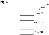
- FIG. 10 shows a schematic representation of a flowchart on the basis of a method 100 for operating an electrical machine 2.
- a step 110 the connections of the electrical machine 2 are first activated with an alternating voltage. This control of the electrical machine 2 takes place in order to set a predetermined torque or a predetermined speed, as is carried out in normal operation. If a malfunction occurs during this control mode, it may be necessary to end the control mode and switch to free-running mode. If an event is detected that requires the change from control mode to freewheeling mode, control mode is terminated and, in step 120, the amplitude of the alternating voltage with which the electrical machine is controlled is set to a predetermined value. This predetermined value is preferably the freewheeling voltage of the electrical machine at the current speed. This speed-dependent freewheeling voltage of the electrical machine can be calculated beforehand in a further step or, alternatively, can also be read from a memory.
- the changeover to freewheeling then takes place.
- the electrical machine is no longer actively controlled. Rather, the connections of the electrical machine 2 are electrically isolated from one another in this freewheel.
- the switching elements of an inverter that controls the electrical machine 2 in regular operation are all open in this switching state.
- the present invention relates to changing an electrical machine from normal operation to freewheeling.
- a further control phase is introduced between the end of normal operation and freewheeling, during which the voltage at the connections of the electric machine from the previous
- the voltage set in normal operation is continuously adapted to the expected free-wheeling voltage of the electrical machine.
Landscapes
- Engineering & Computer Science (AREA)
- Power Engineering (AREA)
- Transportation (AREA)
- Mechanical Engineering (AREA)
- Life Sciences & Earth Sciences (AREA)
- Sustainable Development (AREA)
- Sustainable Energy (AREA)
- Control Of Ac Motors In General (AREA)
- Control Of Motors That Do Not Use Commutators (AREA)
Claims (7)
- Dispositif destiné à faire fonctionner une machine électrique (2) pour passer du fonctionnement normal à un fonctionnement en roue libre,
ledit dispositif comprenant un onduleur (1),
l'onduleur comprenant une pluralité d'éléments de commutation (10a-10f),
l'onduleur produisant une tension alternative aux bornes de la machine électrique (2) en fonctionnement normal par commande des éléments de commutation (10a-10f),
l'onduleur séparant électriquement les bornes de la machine électrique (2) les unes des autres en fonctionnement en roue libre par ouverture des éléments de commutation (10a-10f),
l'onduleur étant conçu pour produire une tension alternative aux bornes de la machine électrique (2) en fonctionnement normal, et pour isoler électriquement les bornes de la machine électrique (2) les unes des autres en fonctionnement en roue libre,
caractérisé en ce que
l'onduleur (1) est conçu pour régler l'amplitude de la tension alternative, produite aux bornes de la machine électrique (2), à une valeur prédéterminée dans un intervalle de temps prédéterminé pendant une transition du fonctionnement normal au fonctionnement en roue libre. - Dispositif selon la revendication 1, comprenant un régulateur (11) qui est conçu pour déterminer une vitesse de rotation de la machine électrique (2) et pour déterminer une tension qui correspond à la tension aux bornes de la machine électrique (2) dans le fonctionnement en roue libre, l'onduleur (11) réglant initialement l'amplitude de la tension aux bornes de la machine électrique (2) à la tension déterminée lors d'une transition du fonctionnement normal au fonctionnement en roue libre.
- Dispositif selon la revendication 2, comprenant un capteur de vitesse de rotation (20) qui est conçu pour déterminer la vitesse de la machine électrique (2).
- Dispositif d'entraînement électrique comprenant :une machine électrique (2) ; etun dispositif selon l'une des revendications 1 à 3.
- Véhicule automobile comprenant un dispositif d'entraînement électrique selon la revendication 4.
- Procédé (100) de fonctionnement d'une machine électrique (2) pour passer d'un fonctionnement normal à un fonctionnement en roue libre, le procédé comprenant les étapes suivantes :appliquer (110) aux bornes de la machine électrique (2) une tension alternative dans un fonctionnement normal ;détecter une signalisation pour passer du fonctionnement normal au fonctionnement en roue libre ;régler (120) l'amplitude de la tension alternative avec laquelle la machine électrique (2) est commandée, à une valeur prédéterminée dans un intervalle de temps prédéterminé ; etle passage en roue libre étant après le réglage de l'amplitude de la tension alternative aux bornes de la machine électrique (2), les bornes de la machine électrique (2) étant isolées électriquement (130) les unes des autres pendant la roue libre.
- Procédé (100) selon la revendication 6, l'étape (120) de réglage de la tension alternative commandant la machine électrique (2) avec une tension alternative qui correspond à une tension aux bornes de la machine électrique en roue libre.
Applications Claiming Priority (2)
| Application Number | Priority Date | Filing Date | Title |
|---|---|---|---|
| DE102013226577.8A DE102013226577A1 (de) | 2013-12-19 | 2013-12-19 | Vorrichtung und Verfahren zum Betreiben einer elektrischen Maschine |
| PCT/EP2014/074594 WO2015090756A1 (fr) | 2013-12-19 | 2014-11-14 | Dispositif et procédé de conduite d'une machine électrique |
Publications (2)
| Publication Number | Publication Date |
|---|---|
| EP3083319A1 EP3083319A1 (fr) | 2016-10-26 |
| EP3083319B1 true EP3083319B1 (fr) | 2021-06-09 |
Family
ID=51905047
Family Applications (1)
| Application Number | Title | Priority Date | Filing Date |
|---|---|---|---|
| EP14799738.1A Active EP3083319B1 (fr) | 2013-12-19 | 2014-11-14 | Appareil et procede pour faire fonctionner une machine électrique |
Country Status (5)
| Country | Link |
|---|---|
| US (1) | US9825571B2 (fr) |
| EP (1) | EP3083319B1 (fr) |
| CN (1) | CN105813880B (fr) |
| DE (1) | DE102013226577A1 (fr) |
| WO (1) | WO2015090756A1 (fr) |
Families Citing this family (1)
| Publication number | Priority date | Publication date | Assignee | Title |
|---|---|---|---|---|
| FR3115944A1 (fr) * | 2020-11-03 | 2022-05-06 | Nidec Psa Emotors | Procédé de pilotage d’un onduleur et système correspondant |
Family Cites Families (16)
| Publication number | Priority date | Publication date | Assignee | Title |
|---|---|---|---|---|
| JPH0984208A (ja) * | 1995-09-14 | 1997-03-28 | Denso Corp | 電気自動車用制御装置 |
| US5874818A (en) * | 1997-06-11 | 1999-02-23 | Agile Systems, Inc. | Method and apparatus for sensing load current in a motor controller |
| DE10146527A1 (de) * | 2001-09-21 | 2003-04-24 | Siemens Ag | Umrichter mit einem netz- und lastseitigen selbstgeführten Pulsstromrichter |
| JP3672876B2 (ja) * | 2002-02-26 | 2005-07-20 | 株式会社東芝 | ベクトル制御インバータ装置及び回転駆動装置 |
| GB2413905B (en) * | 2004-05-05 | 2006-05-03 | Imra Europ S A S Uk Res Ct | Permanent magnet synchronous motor and controller therefor |
| DE102006003254A1 (de) * | 2006-01-24 | 2007-07-26 | Robert Bosch Gmbh | Verfahren zum Abschalten einer elektrischen Maschine im Falle einer Störung |
| JP4085112B2 (ja) * | 2006-01-31 | 2008-05-14 | ファナック株式会社 | モータ制御方法およびモータ制御装置 |
| DE102006018053A1 (de) * | 2006-04-19 | 2007-10-31 | Daimlerchrysler Ag | Ansteuersystem für eine elektrische Maschine |
| US7279862B1 (en) * | 2006-08-04 | 2007-10-09 | Gm Global Technology Operations, Inc. | Fault handling of inverter driven PM motor drives |
| US7489097B2 (en) * | 2006-11-02 | 2009-02-10 | Chrysler Llc | Sensorless position detection for a brushless direct current motor during inverter standby |
| DE102007020509A1 (de) | 2007-05-02 | 2008-11-06 | Robert Bosch Gmbh | Fehlerbehandlung bei einer elektrischen Maschine eines Hybridantriebes |
| US8319460B2 (en) * | 2009-10-27 | 2012-11-27 | GM Global Technology Operations LLC | Method and system for initiating operation of an electric motor |
| DE102009047616A1 (de) | 2009-12-08 | 2011-06-09 | Robert Bosch Gmbh | Wechselrichteranordnung zum Betreiben eines Elektromotors |
| DE102012002023A1 (de) * | 2011-06-21 | 2012-12-27 | Volkswagen Aktiengesellschaft | Verfahren und Vorrichtung zum Betreiben einer Wechselrichterschaltung einer Elektromaschine |
| DE102011079566B4 (de) * | 2011-07-21 | 2024-09-05 | Robert Bosch Gmbh | Verfahren zum Betreiben eines elektrischen Netzes und Vorrichtung zum Steuern eines elektrischen Netzes |
| DE102012101508A1 (de) | 2012-02-24 | 2013-08-29 | Volkswagen Aktiengesellschaft | Verfahren und Vorrichtung zum Betreiben einer elektrischen Maschine |
-
2013
- 2013-12-19 DE DE102013226577.8A patent/DE102013226577A1/de active Pending
-
2014
- 2014-11-14 WO PCT/EP2014/074594 patent/WO2015090756A1/fr not_active Ceased
- 2014-11-14 CN CN201480069836.5A patent/CN105813880B/zh active Active
- 2014-11-14 EP EP14799738.1A patent/EP3083319B1/fr active Active
- 2014-11-14 US US15/104,590 patent/US9825571B2/en active Active
Non-Patent Citations (1)
| Title |
|---|
| None * |
Also Published As
| Publication number | Publication date |
|---|---|
| US9825571B2 (en) | 2017-11-21 |
| US20160380569A1 (en) | 2016-12-29 |
| DE102013226577A1 (de) | 2015-06-25 |
| EP3083319A1 (fr) | 2016-10-26 |
| CN105813880B (zh) | 2018-01-26 |
| WO2015090756A1 (fr) | 2015-06-25 |
| CN105813880A (zh) | 2016-07-27 |
Similar Documents
| Publication | Publication Date | Title |
|---|---|---|
| EP3083320B1 (fr) | Appareil et procede pour faire fonctionner une machine électrique | |
| EP3083321B1 (fr) | Appareil et procede pour faire fonctionner une machine électrique | |
| DE10050383B4 (de) | Hybridfahrzeug und Verfahren zur Erzeugung einer Antriebskraft eines Hybridfahrzeugs | |
| DE102015218732A1 (de) | Elektromotorantriebssteuervorrichtung, elektrisch betriebene Servolenkungsvorrichtung, elektrisch betriebene Bremsvorrichtung und elektrisch betriebene Pumpvorrichtung | |
| DE112007001580T5 (de) | Wechselrichtersteuereinrichtung und Verfahren zu deren Betrieb | |
| WO2008138864A1 (fr) | Procédé et dispositif de fonctionnement d'une unité de commande pour commander une machine électrique | |
| EP3058652B1 (fr) | Appareil de commande à débranchement de sécurité | |
| WO2005048446A1 (fr) | Procede pour freiner une machine synchrone | |
| DE102017108396A1 (de) | Fehlerabschaltsteuerung einer elektrischen maschine in einem fahrzeug oder anderen gleichstromdrehmomentsystemen | |
| EP3145750A1 (fr) | Procédé de commutation d'un onduleur d'un entraînement électrique d'un véhicule automobile et onduleur pouvant être commuté de manière correspondante | |
| EP3545617B1 (fr) | Dispositif de protection pour système d'entraînement électrique, système d'entraînement électrique et procédé pour faire fonctionner un système d'entraînement électrique | |
| DE102011075789A1 (de) | Verfahren zum Betrieb einer Drehfeldmaschine | |
| DE112021006811T5 (de) | Motorantriebsvorrichtung mit ladesteuereinheit | |
| EP4256691B1 (fr) | Procédé pour faire fonctionner une machine électrique, dispositif pour faire fonctionner une machine électrique et système d'entraînement électrique | |
| EP3083319B1 (fr) | Appareil et procede pour faire fonctionner une machine électrique | |
| DE102018203515A1 (de) | Steuersystem, Steuereinrichtung und Steuerverfahren für eine gewickelte Induktionsmaschine | |
| EP2570290A1 (fr) | Système d'entraînement d'un véhicule fonctionnant sur batterie doté d'une machine synchrone à excitation permanente alimentée par convertisseur | |
| EP2654155B1 (fr) | Convertisseur de courant, tout comme procédé destiné au fonctionnement d'un convertisseur de courant | |
| EP3172831A1 (fr) | Procédé de commande d'au moins une machine électrique pouvant fonctionner en générateur et moyen pour mettre en oeuvre celui-ci | |
| DE102015104466A1 (de) | Elektrofahrzeug und verfahren | |
| DE102009049623A1 (de) | Verfahren und Vorrichtung zur Regelung der Spannung eines Zwischenkreises eines Kraftfahrzeugs | |
| DE102014222939B4 (de) | Fahrzeugelektro-Stromumwandlungsvorrichtung | |
| EP2560277B1 (fr) | Protection d'un moteur triphasé dans la zone d'affaiblissement de champ | |
| DE102017217865A1 (de) | Überwachung der für eine Strommessung an einer elektrischen Spule erforderlichen Messkomponenten | |
| DE102024106471A1 (de) | Wischersteuereinrichtung |
Legal Events
| Date | Code | Title | Description |
|---|---|---|---|
| PUAI | Public reference made under article 153(3) epc to a published international application that has entered the european phase |
Free format text: ORIGINAL CODE: 0009012 |
|
| 17P | Request for examination filed |
Effective date: 20160719 |
|
| AK | Designated contracting states |
Kind code of ref document: A1 Designated state(s): AL AT BE BG CH CY CZ DE DK EE ES FI FR GB GR HR HU IE IS IT LI LT LU LV MC MK MT NL NO PL PT RO RS SE SI SK SM TR |
|
| AX | Request for extension of the european patent |
Extension state: BA ME |
|
| DAX | Request for extension of the european patent (deleted) | ||
| STAA | Information on the status of an ep patent application or granted ep patent |
Free format text: STATUS: EXAMINATION IS IN PROGRESS |
|
| 17Q | First examination report despatched |
Effective date: 20200120 |
|
| RAP1 | Party data changed (applicant data changed or rights of an application transferred) |
Owner name: ROBERT BOSCH GMBH |
|
| REG | Reference to a national code |
Ref country code: DE Ref legal event code: R079 Ref document number: 502014015663 Country of ref document: DE Free format text: PREVIOUS MAIN CLASS: B60L0003000000 Ipc: H02P0025024000 |
|
| RIC1 | Information provided on ipc code assigned before grant |
Ipc: H02P 25/024 20160101AFI20200917BHEP Ipc: H02P 27/08 20060101ALI20200917BHEP Ipc: H02P 29/024 20160101ALI20200917BHEP Ipc: H02P 3/18 20060101ALI20200917BHEP Ipc: H02P 23/14 20060101ALI20200917BHEP |
|
| GRAP | Despatch of communication of intention to grant a patent |
Free format text: ORIGINAL CODE: EPIDOSNIGR1 |
|
| GRAJ | Information related to disapproval of communication of intention to grant by the applicant or resumption of examination proceedings by the epo deleted |
Free format text: ORIGINAL CODE: EPIDOSDIGR1 |
|
| GRAP | Despatch of communication of intention to grant a patent |
Free format text: ORIGINAL CODE: EPIDOSNIGR1 |
|
| STAA | Information on the status of an ep patent application or granted ep patent |
Free format text: STATUS: GRANT OF PATENT IS INTENDED |
|
| INTG | Intention to grant announced |
Effective date: 20201204 |
|
| GRAJ | Information related to disapproval of communication of intention to grant by the applicant or resumption of examination proceedings by the epo deleted |
Free format text: ORIGINAL CODE: EPIDOSDIGR1 |
|
| STAA | Information on the status of an ep patent application or granted ep patent |
Free format text: STATUS: EXAMINATION IS IN PROGRESS |
|
| GRAP | Despatch of communication of intention to grant a patent |
Free format text: ORIGINAL CODE: EPIDOSNIGR1 |
|
| STAA | Information on the status of an ep patent application or granted ep patent |
Free format text: STATUS: GRANT OF PATENT IS INTENDED |
|
| INTC | Intention to grant announced (deleted) | ||
| INTG | Intention to grant announced |
Effective date: 20210225 |
|
| GRAS | Grant fee paid |
Free format text: ORIGINAL CODE: EPIDOSNIGR3 |
|
| GRAA | (expected) grant |
Free format text: ORIGINAL CODE: 0009210 |
|
| STAA | Information on the status of an ep patent application or granted ep patent |
Free format text: STATUS: THE PATENT HAS BEEN GRANTED |
|
| AK | Designated contracting states |
Kind code of ref document: B1 Designated state(s): AL AT BE BG CH CY CZ DE DK EE ES FI FR GB GR HR HU IE IS IT LI LT LU LV MC MK MT NL NO PL PT RO RS SE SI SK SM TR |
|
| REG | Reference to a national code |
Ref country code: GB Ref legal event code: FG4D Free format text: NOT ENGLISH |
|
| REG | Reference to a national code |
Ref country code: CH Ref legal event code: EP Ref country code: AT Ref legal event code: REF Ref document number: 1401314 Country of ref document: AT Kind code of ref document: T Effective date: 20210615 |
|
| REG | Reference to a national code |
Ref country code: DE Ref legal event code: R096 Ref document number: 502014015663 Country of ref document: DE |
|
| REG | Reference to a national code |
Ref country code: IE Ref legal event code: FG4D Free format text: LANGUAGE OF EP DOCUMENT: GERMAN |
|
| REG | Reference to a national code |
Ref country code: LT Ref legal event code: MG9D |
|
| PG25 | Lapsed in a contracting state [announced via postgrant information from national office to epo] |
Ref country code: HR Free format text: LAPSE BECAUSE OF FAILURE TO SUBMIT A TRANSLATION OF THE DESCRIPTION OR TO PAY THE FEE WITHIN THE PRESCRIBED TIME-LIMIT Effective date: 20210609 Ref country code: BG Free format text: LAPSE BECAUSE OF FAILURE TO SUBMIT A TRANSLATION OF THE DESCRIPTION OR TO PAY THE FEE WITHIN THE PRESCRIBED TIME-LIMIT Effective date: 20210909 Ref country code: LT Free format text: LAPSE BECAUSE OF FAILURE TO SUBMIT A TRANSLATION OF THE DESCRIPTION OR TO PAY THE FEE WITHIN THE PRESCRIBED TIME-LIMIT Effective date: 20210609 Ref country code: FI Free format text: LAPSE BECAUSE OF FAILURE TO SUBMIT A TRANSLATION OF THE DESCRIPTION OR TO PAY THE FEE WITHIN THE PRESCRIBED TIME-LIMIT Effective date: 20210609 |
|
| REG | Reference to a national code |
Ref country code: NL Ref legal event code: MP Effective date: 20210609 |
|
| PG25 | Lapsed in a contracting state [announced via postgrant information from national office to epo] |
Ref country code: GR Free format text: LAPSE BECAUSE OF FAILURE TO SUBMIT A TRANSLATION OF THE DESCRIPTION OR TO PAY THE FEE WITHIN THE PRESCRIBED TIME-LIMIT Effective date: 20210910 Ref country code: LV Free format text: LAPSE BECAUSE OF FAILURE TO SUBMIT A TRANSLATION OF THE DESCRIPTION OR TO PAY THE FEE WITHIN THE PRESCRIBED TIME-LIMIT Effective date: 20210609 Ref country code: RS Free format text: LAPSE BECAUSE OF FAILURE TO SUBMIT A TRANSLATION OF THE DESCRIPTION OR TO PAY THE FEE WITHIN THE PRESCRIBED TIME-LIMIT Effective date: 20210609 Ref country code: SE Free format text: LAPSE BECAUSE OF FAILURE TO SUBMIT A TRANSLATION OF THE DESCRIPTION OR TO PAY THE FEE WITHIN THE PRESCRIBED TIME-LIMIT Effective date: 20210609 Ref country code: NO Free format text: LAPSE BECAUSE OF FAILURE TO SUBMIT A TRANSLATION OF THE DESCRIPTION OR TO PAY THE FEE WITHIN THE PRESCRIBED TIME-LIMIT Effective date: 20210909 |
|
| PG25 | Lapsed in a contracting state [announced via postgrant information from national office to epo] |
Ref country code: SM Free format text: LAPSE BECAUSE OF FAILURE TO SUBMIT A TRANSLATION OF THE DESCRIPTION OR TO PAY THE FEE WITHIN THE PRESCRIBED TIME-LIMIT Effective date: 20210609 Ref country code: SK Free format text: LAPSE BECAUSE OF FAILURE TO SUBMIT A TRANSLATION OF THE DESCRIPTION OR TO PAY THE FEE WITHIN THE PRESCRIBED TIME-LIMIT Effective date: 20210609 Ref country code: CZ Free format text: LAPSE BECAUSE OF FAILURE TO SUBMIT A TRANSLATION OF THE DESCRIPTION OR TO PAY THE FEE WITHIN THE PRESCRIBED TIME-LIMIT Effective date: 20210609 Ref country code: EE Free format text: LAPSE BECAUSE OF FAILURE TO SUBMIT A TRANSLATION OF THE DESCRIPTION OR TO PAY THE FEE WITHIN THE PRESCRIBED TIME-LIMIT Effective date: 20210609 Ref country code: RO Free format text: LAPSE BECAUSE OF FAILURE TO SUBMIT A TRANSLATION OF THE DESCRIPTION OR TO PAY THE FEE WITHIN THE PRESCRIBED TIME-LIMIT Effective date: 20210609 Ref country code: NL Free format text: LAPSE BECAUSE OF FAILURE TO SUBMIT A TRANSLATION OF THE DESCRIPTION OR TO PAY THE FEE WITHIN THE PRESCRIBED TIME-LIMIT Effective date: 20210609 Ref country code: PT Free format text: LAPSE BECAUSE OF FAILURE TO SUBMIT A TRANSLATION OF THE DESCRIPTION OR TO PAY THE FEE WITHIN THE PRESCRIBED TIME-LIMIT Effective date: 20211011 Ref country code: ES Free format text: LAPSE BECAUSE OF FAILURE TO SUBMIT A TRANSLATION OF THE DESCRIPTION OR TO PAY THE FEE WITHIN THE PRESCRIBED TIME-LIMIT Effective date: 20210609 |
|
| PG25 | Lapsed in a contracting state [announced via postgrant information from national office to epo] |
Ref country code: PL Free format text: LAPSE BECAUSE OF FAILURE TO SUBMIT A TRANSLATION OF THE DESCRIPTION OR TO PAY THE FEE WITHIN THE PRESCRIBED TIME-LIMIT Effective date: 20210609 |
|
| REG | Reference to a national code |
Ref country code: DE Ref legal event code: R097 Ref document number: 502014015663 Country of ref document: DE |
|
| PLBE | No opposition filed within time limit |
Free format text: ORIGINAL CODE: 0009261 |
|
| STAA | Information on the status of an ep patent application or granted ep patent |
Free format text: STATUS: NO OPPOSITION FILED WITHIN TIME LIMIT |
|
| PG25 | Lapsed in a contracting state [announced via postgrant information from national office to epo] |
Ref country code: DK Free format text: LAPSE BECAUSE OF FAILURE TO SUBMIT A TRANSLATION OF THE DESCRIPTION OR TO PAY THE FEE WITHIN THE PRESCRIBED TIME-LIMIT Effective date: 20210609 |
|
| 26N | No opposition filed |
Effective date: 20220310 |
|
| PG25 | Lapsed in a contracting state [announced via postgrant information from national office to epo] |
Ref country code: AL Free format text: LAPSE BECAUSE OF FAILURE TO SUBMIT A TRANSLATION OF THE DESCRIPTION OR TO PAY THE FEE WITHIN THE PRESCRIBED TIME-LIMIT Effective date: 20210609 |
|
| PG25 | Lapsed in a contracting state [announced via postgrant information from national office to epo] |
Ref country code: MC Free format text: LAPSE BECAUSE OF FAILURE TO SUBMIT A TRANSLATION OF THE DESCRIPTION OR TO PAY THE FEE WITHIN THE PRESCRIBED TIME-LIMIT Effective date: 20210609 |
|
| REG | Reference to a national code |
Ref country code: CH Ref legal event code: PL |
|
| PG25 | Lapsed in a contracting state [announced via postgrant information from national office to epo] |
Ref country code: LU Free format text: LAPSE BECAUSE OF NON-PAYMENT OF DUE FEES Effective date: 20211114 Ref country code: BE Free format text: LAPSE BECAUSE OF NON-PAYMENT OF DUE FEES Effective date: 20211130 |
|
| REG | Reference to a national code |
Ref country code: BE Ref legal event code: MM Effective date: 20211130 |
|
| PG25 | Lapsed in a contracting state [announced via postgrant information from national office to epo] |
Ref country code: LI Free format text: LAPSE BECAUSE OF NON-PAYMENT OF DUE FEES Effective date: 20211130 Ref country code: CH Free format text: LAPSE BECAUSE OF NON-PAYMENT OF DUE FEES Effective date: 20211130 |
|
| PG25 | Lapsed in a contracting state [announced via postgrant information from national office to epo] |
Ref country code: IE Free format text: LAPSE BECAUSE OF NON-PAYMENT OF DUE FEES Effective date: 20211114 |
|
| REG | Reference to a national code |
Ref country code: AT Ref legal event code: MM01 Ref document number: 1401314 Country of ref document: AT Kind code of ref document: T Effective date: 20211114 |
|
| PG25 | Lapsed in a contracting state [announced via postgrant information from national office to epo] |
Ref country code: AT Free format text: LAPSE BECAUSE OF NON-PAYMENT OF DUE FEES Effective date: 20211114 |
|
| PG25 | Lapsed in a contracting state [announced via postgrant information from national office to epo] |
Ref country code: HU Free format text: LAPSE BECAUSE OF FAILURE TO SUBMIT A TRANSLATION OF THE DESCRIPTION OR TO PAY THE FEE WITHIN THE PRESCRIBED TIME-LIMIT; INVALID AB INITIO Effective date: 20141114 |
|
| PG25 | Lapsed in a contracting state [announced via postgrant information from national office to epo] |
Ref country code: CY Free format text: LAPSE BECAUSE OF FAILURE TO SUBMIT A TRANSLATION OF THE DESCRIPTION OR TO PAY THE FEE WITHIN THE PRESCRIBED TIME-LIMIT Effective date: 20210609 |
|
| PG25 | Lapsed in a contracting state [announced via postgrant information from national office to epo] |
Ref country code: MK Free format text: LAPSE BECAUSE OF FAILURE TO SUBMIT A TRANSLATION OF THE DESCRIPTION OR TO PAY THE FEE WITHIN THE PRESCRIBED TIME-LIMIT Effective date: 20210609 |
|
| PG25 | Lapsed in a contracting state [announced via postgrant information from national office to epo] |
Ref country code: MT Free format text: LAPSE BECAUSE OF FAILURE TO SUBMIT A TRANSLATION OF THE DESCRIPTION OR TO PAY THE FEE WITHIN THE PRESCRIBED TIME-LIMIT Effective date: 20210609 |
|
| PGFP | Annual fee paid to national office [announced via postgrant information from national office to epo] |
Ref country code: DE Payment date: 20250122 Year of fee payment: 11 |
|
| PG25 | Lapsed in a contracting state [announced via postgrant information from national office to epo] |
Ref country code: TR Free format text: LAPSE BECAUSE OF FAILURE TO SUBMIT A TRANSLATION OF THE DESCRIPTION OR TO PAY THE FEE WITHIN THE PRESCRIBED TIME-LIMIT Effective date: 20210609 |
|
| PGFP | Annual fee paid to national office [announced via postgrant information from national office to epo] |
Ref country code: GB Payment date: 20251120 Year of fee payment: 12 |
|
| PGFP | Annual fee paid to national office [announced via postgrant information from national office to epo] |
Ref country code: IT Payment date: 20251128 Year of fee payment: 12 |
|
| PGFP | Annual fee paid to national office [announced via postgrant information from national office to epo] |
Ref country code: FR Payment date: 20251125 Year of fee payment: 12 |