EP3083320B1 - Appareil et procede pour faire fonctionner une machine électrique - Google Patents
Appareil et procede pour faire fonctionner une machine électrique Download PDFInfo
- Publication number
- EP3083320B1 EP3083320B1 EP14799409.9A EP14799409A EP3083320B1 EP 3083320 B1 EP3083320 B1 EP 3083320B1 EP 14799409 A EP14799409 A EP 14799409A EP 3083320 B1 EP3083320 B1 EP 3083320B1
- Authority
- EP
- European Patent Office
- Prior art keywords
- electrical machine
- voltage
- freewheeling
- inverter
- electrical
- Prior art date
- Legal status (The legal status is an assumption and is not a legal conclusion. Google has not performed a legal analysis and makes no representation as to the accuracy of the status listed.)
- Active
Links
Images


Classifications
-
- H—ELECTRICITY
- H02—GENERATION; CONVERSION OR DISTRIBUTION OF ELECTRIC POWER
- H02P—CONTROL OR REGULATION OF ELECTRIC MOTORS, ELECTRIC GENERATORS OR DYNAMO-ELECTRIC CONVERTERS; CONTROLLING TRANSFORMERS, REACTORS OR CHOKE COILS
- H02P29/00—Arrangements for regulating or controlling electric motors, appropriate for both AC and DC motors
- H02P29/02—Providing protection against overload without automatic interruption of supply
- H02P29/024—Detecting a fault condition, e.g. short circuit, locked rotor, open circuit or loss of load
- H02P29/0241—Detecting a fault condition, e.g. short circuit, locked rotor, open circuit or loss of load the fault being an overvoltage
-
- B—PERFORMING OPERATIONS; TRANSPORTING
- B60—VEHICLES IN GENERAL
- B60L—PROPULSION OF ELECTRICALLY-PROPELLED VEHICLES; SUPPLYING ELECTRIC POWER FOR AUXILIARY EQUIPMENT OF ELECTRICALLY-PROPELLED VEHICLES; ELECTRODYNAMIC BRAKE SYSTEMS FOR VEHICLES IN GENERAL; MAGNETIC SUSPENSION OR LEVITATION FOR VEHICLES; MONITORING OPERATING VARIABLES OF ELECTRICALLY-PROPELLED VEHICLES; ELECTRIC SAFETY DEVICES FOR ELECTRICALLY-PROPELLED VEHICLES
- B60L3/00—Electric devices on electrically-propelled vehicles for safety purposes; Monitoring operating variables, e.g. speed, deceleration or energy consumption
- B60L3/04—Cutting off the power supply under fault conditions
-
- H—ELECTRICITY
- H02—GENERATION; CONVERSION OR DISTRIBUTION OF ELECTRIC POWER
- H02P—CONTROL OR REGULATION OF ELECTRIC MOTORS, ELECTRIC GENERATORS OR DYNAMO-ELECTRIC CONVERTERS; CONTROLLING TRANSFORMERS, REACTORS OR CHOKE COILS
- H02P23/00—Arrangements or methods for the control of AC motors characterised by a control method other than vector control
- H02P23/0004—Control strategies in general, e.g. linear type, e.g. P, PI, PID, using robust control
- H02P23/0027—Control strategies in general, e.g. linear type, e.g. P, PI, PID, using robust control using different modes of control depending on a parameter, e.g. the speed
-
- H—ELECTRICITY
- H02—GENERATION; CONVERSION OR DISTRIBUTION OF ELECTRIC POWER
- H02P—CONTROL OR REGULATION OF ELECTRIC MOTORS, ELECTRIC GENERATORS OR DYNAMO-ELECTRIC CONVERTERS; CONTROLLING TRANSFORMERS, REACTORS OR CHOKE COILS
- H02P27/00—Arrangements or methods for the control of AC motors characterised by the kind of supply voltage
- H02P27/04—Arrangements or methods for the control of AC motors characterised by the kind of supply voltage using variable-frequency supply voltage, e.g. inverter or converter supply voltage
- H02P27/06—Arrangements or methods for the control of AC motors characterised by the kind of supply voltage using variable-frequency supply voltage, e.g. inverter or converter supply voltage using DC to AC converters or inverters
-
- H—ELECTRICITY
- H02—GENERATION; CONVERSION OR DISTRIBUTION OF ELECTRIC POWER
- H02P—CONTROL OR REGULATION OF ELECTRIC MOTORS, ELECTRIC GENERATORS OR DYNAMO-ELECTRIC CONVERTERS; CONTROLLING TRANSFORMERS, REACTORS OR CHOKE COILS
- H02P3/00—Arrangements for stopping or slowing electric motors, generators, or dynamo-electric converters
- H02P3/06—Arrangements for stopping or slowing electric motors, generators, or dynamo-electric converters for stopping or slowing an individual dynamo-electric motor or dynamo-electric converter
- H02P3/18—Arrangements for stopping or slowing electric motors, generators, or dynamo-electric converters for stopping or slowing an individual dynamo-electric motor or dynamo-electric converter for stopping or slowing an AC motor
-
- Y—GENERAL TAGGING OF NEW TECHNOLOGICAL DEVELOPMENTS; GENERAL TAGGING OF CROSS-SECTIONAL TECHNOLOGIES SPANNING OVER SEVERAL SECTIONS OF THE IPC; TECHNICAL SUBJECTS COVERED BY FORMER USPC CROSS-REFERENCE ART COLLECTIONS [XRACs] AND DIGESTS
- Y02—TECHNOLOGIES OR APPLICATIONS FOR MITIGATION OR ADAPTATION AGAINST CLIMATE CHANGE
- Y02T—CLIMATE CHANGE MITIGATION TECHNOLOGIES RELATED TO TRANSPORTATION
- Y02T10/00—Road transport of goods or passengers
- Y02T10/60—Other road transportation technologies with climate change mitigation effect
- Y02T10/64—Electric machine technologies in electromobility
Definitions
- the present invention relates to an apparatus and a method for operating an electrical machine.
- the present invention relates to a device and a method for operating an electrical machine during the transition of the electrical machine to an active short-circuit operation.
- Electrical machines such as permanently excited synchronous machines, are used for numerous technical applications.
- electrical machines can be used as a drive for a fully or partially electrically operated motor vehicle.
- precautions must be taken for a possible fault.
- a fault can be, for example, a malfunction or a failure of a sensor that delivers measured values for the safe operation of the electrical machine.
- Another fault case can be, for example, the failure of a supply voltage in an electrically operated motor vehicle.
- One possibility for an operating mode in the event of a fault is free-running operation of the electrical machine. In this case, the electrical machine is no longer subjected to an electrical voltage.
- the electrical phase connections of the machine are separated from each other.
- Another safe operating mode is the so-called active short circuit. In the case of this active short circuit, all phase connections of the machine are electrically connected to one another by suitable switching elements.
- DE 10 2007 020 509 A1 relates to the error handling of an electrical machine of a hybrid drive. Before the supply connection of the electrical machine is short-circuited, the electrical machine is driven in free-running mode for a predetermined period of time.
- DE 10 2012 002 023 A1 relates to a method and a device for operating an inverter circuit of an electric machine. If the speed of the electric machine is above a limit value, the electric machine is operated in short-circuit mode. If the speed is below the limit, the electric machine is operated in free-running mode.
- US 7 279 862 B1 concerns the error handling of an inverter-controlled electric motor. If the speed of the motor is greater than a predetermined speed, the motor is operated in freewheel mode. If the speed of the motor is lower than a predetermined speed, the motor is operated in short-circuit mode.
- the present invention provides an apparatus and a method for operating an electrical machine with the features of the independent claims.
- the present invention is based on the idea of first reducing the electrical voltage at the phase connections of an electrical machine in a controlled manner to a suitable voltage level before the electrical machine is switched into an active short circuit.
- the transition from a current operating mode of the electrical machine into the active short circuit does not occur suddenly, but under regulated framework conditions.
- This controlled transition of the electrical voltage at the phase connections of the electrical machine in front of you active short circuit it is possible to convert the machine to the active short circuit without an additional overcurrent being established.
- the inverter is designed to reduce the amplitude of the AC voltage provided at the connections of the electrical machine to 0 volts before a transition from controlled operation to short-circuit operation.
- the voltage at the phase connections of the electrical machine can be reduced to a value of approximately 0 volts or at least reduced to a value which is less than the voltage at the connections of the electrical machine during the controlled operation.
- the electrical machine In free-running mode, the electrical machine is initially not actively controlled. If a switch is to be made from the free-wheeling mode to the active short circuit, the electrical machine can therefore first be controlled with an electrical voltage which at least approximately corresponds to the free-wheeling voltage currently present at the connections of the electrical machine to avoid disproportionately large overcurrents. Thereupon this voltage, with which the electrical machine is then controlled, can be actively reduced to the predetermined value which is required for a gentle change into the active short circuit. That way too a gentle transition from freewheeling operation to active short-circuit is possible without dangerous overcurrents occurring.
- the freewheel voltage generally represents a function dependent on the speed of the electrical machine, an efficient determination of the freewheel voltage on the electrical machine can also be made possible in this case, so that there are no major discrepancies when the electrical machine is actuated with the freewheel voltage comes between the voltage provided by the inverter and the actual freewheeling voltage.
- the device for operating the electrical machine can also have a voltage sensor that detects the electrical voltage at the connections of the machine, with the inverter initially setting the freewheeling voltage detected by the sensor during a transition from freewheeling operation to short-circuiting operation. Based on this voltage, the control can then be adapted to the voltage required for the change to the active short circuit.
- the inverter is designed to set the amplitude of the AC voltage to the predetermined value within a predetermined time period after the controlled operation has ended. In this way, the time period within which the transition from the controlled operation to the short-circuit operation takes place can be predetermined. This also ensures that there is no disproportionate delay in activating the active short circuit.
- the inverter can set the amplitude of the AC voltage provided at the connections of the electrical machine with a predetermined slope, that is to say with a predetermined voltage difference per unit of time, during a transition from the controlled operation to the short-circuit operation. In this way it can be ensured that there are no disproportionately large changes in the tension.
- the present invention further relates to an electrical drive device with an electrical machine and a device according to the invention for operating an electrical machine.
- the electrical machine comprises a permanently excited synchronous machine.
- the present invention relates to a motor vehicle with an electrical machine which is controlled by a device according to the invention for operating the electrical machine.
- FIG. 1 shows a schematic representation of an electric drive system, as based on the present invention.
- the electrical drive system comprises an electrical machine 2 and an inverter 1.
- the inverter 1 is supplied with electrical energy, preferably a DC voltage.
- the DC voltage can originate, for example, from an electrical energy store, such as a battery.
- an electrical energy store such as a battery.
- the electrical energy can also be obtained from an AC voltage network and converted into a DC voltage by means of an AC-DC converter.
- the inverter 1 converts the electrical energy provided at the input into a suitable AC voltage and makes it available at the phase connections of the electrical machine 2.
- the electrical AC voltage provided at the connections of the electrical machine 2 can be set such that a desired speed or a desired torque is achieved by the electrical machine 2.
- the electric drive system can also have one or more sensors (not shown) which, for example, determine the current speed, voltage conditions or phase currents within the electric drive system. These sensor values can then be evaluated by a control system and the control of the inverter 1 can then be adapted based on the predetermined target values.
- the electrical machine 2 is a three-phase electric motor.
- electrical machines with a different number of phase connections are also possible.
- the electrical machine 2 can be, for example, a synchronous machine, preferably a permanently excited synchronous machine. But other electrical machines, such as an asynchronous machine, etc., are also possible.
- the inverter 1 comprises a plurality of switching elements 10a-10f. By suitably controlling these switching elements 10a-10f, the inverter 1 can thus convert an AC voltage from the voltage provided at the input, which AC voltage is provided at the connections of the electrical machine 2. Corresponding to the control of the individual switching elements 10a-10f, an AC voltage with a predetermined amplitude can be generated, for example, by suitable pulsing of these switching elements 10a-10f. The amplitude of the AC voltage generated in this way can be adapted as a function of a torque or a rotational speed of the electrical machine 2 to be achieved.
- the switching elements 10a-10f are preferably semiconductor switching elements, such as IGBT or MOSFET.
- a free-wheeling diode can also be arranged in parallel with each of these switching elements 10a-10f. A current driven by the electrical machine 2 can flow through this freewheeling diode when the semiconductor switch is open.
- FIG 2 shows a schematic representation of an electric drive system in freewheel.
- the switching elements 10a-10f are only shown as simple switches for better illustration.
- each of the switching elements 10a-10f can be a semiconductor switch with a freewheeling diode connected in parallel.
- the switching elements shown each show the state of the corresponding switching elements 10a-10f.
- all switching elements 10a-10f are open.
- the inverter 1 therefore does not provide any voltage to the electrical machine 2. Only the freewheeling voltage generated by the electrical machine 2 in generator operation is present at the connection terminals of the electrical machine 2. If necessary, a current can flow via the freewheeling diodes arranged parallel to the switching elements 10a-10f.
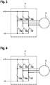
- FIG 3 shows a schematic representation of a control of the electrical machine 2 in an active short circuit according to a first embodiment.
- the upper three switching elements 10a, 10b and 10c are closed.
- the phase connections of the electrical machine 2 are thus electrically connected to one another via these three switching elements 10a-10c, that is to say short-circuited.
- Figure 4 shows an alternative schematic representation for an active short circuit according to a further embodiment.
- the lower switching elements 10d, 10e and 10f are closed, while the upper three switching elements 10a-10c are open.
- the phase connections of the electrical machine 2 are electrically connected to one another via the lower three switching elements 10d-10f and are therefore short-circuited.
- FIG. 5 shows a schematic representation of an electric drive device according to an embodiment of the present invention.
- the electrical drive device comprises an electrical machine 2.
- the electrical machine 2 can be one of the previously mentioned electrical machines, such as a synchronous machine, for example a permanently excited synchronous machine or alternatively also an asynchronous machine or the like.
- the three phase connections for connecting the electrical machine 2 to the inverter 1 are to be understood only as examples. Any other number of phase connections is also possible.
- the electrical machine 2 is controlled by an inverter 1.
- the inverter 1 provides a suitable AC voltage signal at the phase connections of the electrical machine 2. In this way, it is possible to operate the electrical machine 2 at a predetermined speed or a predetermined torque.
- the electrical machine 2 according to FIG Figure 3 or Figure 4 are put into the active short circuit by the inverter 1 and thus a safe state of the electrical machine 2 is established.
- phase connections of the electrical machine 2 are not immediately electrically connected to one another.
- the control device 11 of the inverter 1 detects a fault, or receives a request for an active short circuit via a further connection A
- the voltage at the phase connections of the electrical machine 2 is first continuously adjusted to a value which enables a change to the active short circuit without overcurrents occurring.
- this can be a previously defined voltage value, that is to say an AC voltage with a predetermined amplitude, to which the voltages at the phase connections of the electrical machine 2 are initially regulated.
- the voltage applied to the phase connections of the electrical machine 2 at the time of the request for an active short circuit is continuously reduced to a lower voltage value.
- the voltage at the phase connections of the electrical machine 2 is preferably reduced from the current value to 0 volts when the voltage is reduced.
- the amplitude of the AC voltage which is present at the phase connections of the electrical machine 2 at the start of the request for an active short circuit can be adjusted within a predetermined time interval to the predetermined value which is required for a change to the active short circuit.
- this time interval can be a time interval of a few milliseconds, for example 20 milliseconds, 10 milliseconds, 5 milliseconds or even just 1 millisecond. In this way it can be ensured that the active short circuit can actually be realized within a short time and that there are no major delays in setting a safe state, particularly in the event of an error.
- the change from the current phase voltage at the connections of the electrical machine 2 to the value for the change to the active state can also be carried out with a predetermined maximum slope. This means that the amplitude of the voltage present at the phase connections of the electrical machine 2 is changed by a predetermined value at most per unit of time. In this way it can be ensured that there are no disproportionately large voltage jumps when the electrical machine 2 is actuated.
- the change in the voltage ratios at the phase connections of the electrical machine 2 is preferably linear, that is, the amplitude of the voltage at the phase connections is carried out over the entire period with a constant voltage change per unit of time.
- alternative variations of the voltage values for setting the predetermined voltage for the change to the active short circuit are also possible.
- U d, init and U q, init are the two initial voltage values at the beginning of the request for an active short circuit and ⁇ t the time period during which the active short circuit is to be changed.
- the voltages at the phase connections of the electrical machine 2 are reduced from the initial values at the beginning of the request for an active short circuit to 0 volts when changing to the active short circuit, without this requiring a measurement of the phase currents.
- sensor values about the current state of the electrical drive device such as the phase currents or to allow the current voltage conditions on the electrical machine 2 to be incorporated into the control process.
- the electrical machine 2 must first be actively controlled by the inverter 1. During this activation of the electrical machine 2 by the inverter 1, the voltage at the phase connections of the electrical machine 2 can be reduced to a predetermined value, for example 0 volts, as already described above. In order not to cause voltage jumps at the beginning of this active control, when changing from free-wheeling operation to controlled operation, the electrical machine 2 is first controlled with a voltage that corresponds to the free-wheeling voltage of the electrical machine 2.
- the electrical drive device can have a voltage sensor 12 which measures the voltages at the phase connections of the electrical machine 2. The voltage values measured in this way are provided to the controller 11 of the inverter 1, whereupon the inverter 1 provides an AC voltage at the phase connections of the electrical machine 2 which corresponds to these voltage values.
- the current speed of the electrical machine 2 via a speed sensor 20 and to determine the current free-wheeling voltage of the electrical machine 2 from this.
- the relationships between the speed and the corresponding freewheeling voltage of the electrical machine 2 can be stored in a memory. After determining the current speed of the electrical machine 2, the corresponding freewheeling voltage can thus be read out from this memory and at the connections of the electrical machine can be set.
- Other options for determining or calculating the freewheeling voltage are also possible.
- a sensory measurement of the current speed of the electrical machine 2 it is also possible to determine the speed based on a model, estimated values or the last actively regulated speed. Other possibilities for determining the speed of the electrical machine 2 in the freewheel are also possible.
- the AC voltage provided by the inverter 1 at the phase connections of the electrical machine 2 is then continuously reduced to a predetermined value. If this predetermined value is reached, the inverter 1 then switches to the active short circuit, for example in accordance with Figure 3 or 4 .
- FIG. 6 shows a schematic illustration of a flowchart as it is based on a method 100 for operating an electrical machine 2.
- the electrical machine 2 In a control mode in which the electrical machine 2 is to be operated at a predetermined speed or a predetermined torque, the electrical machine 2 is controlled with a corresponding AC voltage. If an electrical machine 2 controlled in this way should switch to the active short circuit, the amplitude of the AC voltage at the connections of the electrical machine is set to a predetermined value after the occurrence of a corresponding event, for example the detection of a fault or a direct request for the active short circuit . This setting of the AC voltage to the predetermined value takes place on the basis of the voltage with which the electrical machine is controlled in control operation to the predetermined value within a predetermined time period or with a predetermined slope. After the predetermined value of the AC voltage has been set at the connections of the electrical machine, the connections of the electrical machine are electrically connected to one another in step 130 and thus short-circuited.
- step 105 If the electrical machine is operated in a free-wheeling mode in a step 105, in which the connections of the electrical machine are electrically separated from one another, it is first necessary to control the electrical machine in a defined manner. For this a free-wheeling voltage is determined in step 106, which corresponds to the voltage at the connections of the electrical machine in a free-wheeling mode. The electrical machine is then actuated with the determined freewheeling voltage in step 110 described above.
- the present invention relates to a method and a device for operating an electrical machine for a smooth change from a regulating or freewheeling operation to an active short circuit.
- a voltage with which the electrical machine is controlled is first regulated down to a predetermined, preferably very low value and only then short-circuited the phase connections of the electrical machine. In this way, disproportionately large overcurrents, in particular overcurrents that are greater than the nominal current of the electrical machine, can be avoided.
Landscapes
- Engineering & Computer Science (AREA)
- Power Engineering (AREA)
- Life Sciences & Earth Sciences (AREA)
- Sustainable Development (AREA)
- Sustainable Energy (AREA)
- Transportation (AREA)
- Mechanical Engineering (AREA)
- Control Of Ac Motors In General (AREA)
Claims (7)
- Dispositif pour faire fonctionner une machine électrique (2), comportant
un onduleur (1) qui comprend une pluralité d'éléments de commutation (10a-10f) et qui est conçu pour fournir une tension alternative aux bornes de la machine électrique (2) en commandant les éléments de commutation (10a-10f) dans un mode commandé, pour séparer électriquement les unes des autres les bornes de la machine électrique (2) dans un mode de roue libre et pour relier électriquement les unes aux autres les bornes de la machine électrique (2) dans un mode de court-circuit, et
un capteur de vitesse de rotation (20) conçu pour déterminer la vitesse de rotation de la machine électrique (2),
dans lequel l'onduleur (1) est conçu pour régler l'amplitude de la tension alternative fournie aux bornes de la machine électrique (2) à une valeur prédéterminée lors d'une transition du mode commandé au mode de court-circuit ; et
dans lequel l'onduleur (1) est conçu pour déterminer initialement une tension de roue libre en fonction de la vitesse de rotation pendant une transition entre le mode de roue libre et le mode de court-circuit et pour fournir aux bornes de la machine électrique (2) la tension de roue libre déterminée en fonction de la vitesse de rotation. - Dispositif selon la revendication 1, dans lequel l'onduleur (1) est conçu pour réduire l'amplitude de la tension alternative fournie aux bornes de la machine électrique (2) à 0 volt en commandant les éléments de commutation (10a, -10f) avant une transition du mode commandé au mode de court-circuit.
- Dispositif selon la revendication 1 ou 2, dans lequel l'onduleur (1) est conçu pour régler l'amplitude de la tension alternative à la valeur prédéterminée au cours d'un intervalle de temps prédéterminé.
- Dispositif d'entraînement électrique, comprenant :une machine électrique (2) ; etun dispositif selon l'une des revendications 1 à 3.
- Dispositif d'entraînement électrique selon la revendication 4, dans lequel la machine électrique (2) comprend une machine synchrone à excitation permanente.
- Véhicule automobile comportant une machine électrique (2) qui est commandée par un dispositif selon l'une des revendications 1 à 3.
- Procédé (100) pour faire fonctionner une machine électrique (2), comprenant les étapes suivantes :faire fonctionner (105) une machine électrique (2) dans un mode de roue libre, dans lequel les bornes de la machine électrique (2) sont électriquement isolées les unes des autres ;détecter une vitesse de rotation actuelle de la machine électrique (2) à l'aide d'un capteur de vitesse de rotation ;déterminer (106), sur la base de la vitesse de rotation actuelle déterminée de la machine électrique (2), une tension de roue libre dépendant de la vitesse de rotation, qui correspond à la tension aux bornes de la machine électrique (2) dans le mode de roue libre ;commander (110) les bornes de la machine électrique (2) avec la tension de roue libre déterminée en mode commandé ;régler (120) à une valeur prédéterminée l'amplitude de la tension alternative avec laquelle la machine électrique (2) est commandée ; etrelier électriquement (130) les bornes de la machine électrique (2), après que l'amplitude de la tension alternative a été réglée à la valeur prédéterminée, dans un mode de court-circuit.
Applications Claiming Priority (2)
| Application Number | Priority Date | Filing Date | Title |
|---|---|---|---|
| DE102013226564.6A DE102013226564A1 (de) | 2013-12-19 | 2013-12-19 | Vorrichtung und Verfahren zum Betreiben einer elektrischen Maschine |
| PCT/EP2014/074588 WO2015090754A1 (fr) | 2013-12-19 | 2014-11-14 | Dispositif et procédé pour faire fonctionner une machine électrique |
Publications (2)
| Publication Number | Publication Date |
|---|---|
| EP3083320A1 EP3083320A1 (fr) | 2016-10-26 |
| EP3083320B1 true EP3083320B1 (fr) | 2020-08-05 |
Family
ID=51903899
Family Applications (1)
| Application Number | Title | Priority Date | Filing Date |
|---|---|---|---|
| EP14799409.9A Active EP3083320B1 (fr) | 2013-12-19 | 2014-11-14 | Appareil et procede pour faire fonctionner une machine électrique |
Country Status (5)
| Country | Link |
|---|---|
| US (1) | US9825576B2 (fr) |
| EP (1) | EP3083320B1 (fr) |
| CN (1) | CN105813882B (fr) |
| DE (1) | DE102013226564A1 (fr) |
| WO (1) | WO2015090754A1 (fr) |
Cited By (1)
| Publication number | Priority date | Publication date | Assignee | Title |
|---|---|---|---|---|
| WO2023041220A1 (fr) | 2021-09-17 | 2023-03-23 | Robert Bosch Gmbh | Dispositif et procédé de fonctionnement d'une machine électrique |
Families Citing this family (14)
| Publication number | Priority date | Publication date | Assignee | Title |
|---|---|---|---|---|
| JP6740657B2 (ja) * | 2016-03-23 | 2020-08-19 | アイシン・エィ・ダブリュ株式会社 | インバータ装置 |
| DE102017207886A1 (de) * | 2016-06-03 | 2017-12-07 | Robert Bosch Engineering And Business Solutions Private Limited | Steuereinheit und Verfahren zum Ansteuern einer Wechselrichterschaltung für einen Permanentmagnet-Synchronmotor |
| FR3097699B1 (fr) * | 2019-06-18 | 2021-07-16 | Alstom Transp Tech | Procédé d’inhibition d’un onduleur d’une chaîne d’alimentation en puissance électrique d’un moteur à aimants permanents |
| GB2592180B (en) * | 2019-10-08 | 2022-02-23 | Borgwarner Gateshead Ltd | Method and apparatus for controlling electric motors |
| GB2593157B (en) * | 2020-03-11 | 2022-06-08 | Protean Electric Ltd | A circuit for an inverter |
| DE102020112940A1 (de) | 2020-05-13 | 2021-11-18 | Dr. Ing. H.C. F. Porsche Aktiengesellschaft | Verfahren und Vorrichtung zum Betreiben einer Synchronmaschine |
| FR3115944A1 (fr) * | 2020-11-03 | 2022-05-06 | Nidec Psa Emotors | Procédé de pilotage d’un onduleur et système correspondant |
| DE102020215125A1 (de) | 2020-12-01 | 2022-06-02 | Robert Bosch Gesellschaft mit beschränkter Haftung | Verfahren zum Betreiben einer elektrischen Maschine, Vorrichtung zum Betreiben einer elektrischen Maschine, elektrisches Antriebssystem |
| CN112787568A (zh) * | 2021-01-04 | 2021-05-11 | 无锡华宸控制技术有限公司 | 一种用于电机主动短路控制的方法 |
| DE102021201858A1 (de) | 2021-02-26 | 2022-09-01 | Vitesco Technologies Germany Gmbh | Verfahren und Steuereinheit zur Umschaltung eines Elektroantriebs zwischen einem Betriebsmodus mit aktivem Kurzschluss und einem Freilauf-Betriebsmodus |
| DE102022202956B4 (de) * | 2022-03-25 | 2023-11-16 | Vitesco Technologies Germany Gmbh | Hysterese basierte Ansteuerung eines Fahrzeugantriebs mit abwechselndem Freilauf- und Kurzschlusszustand im Fehlerfall |
| DE102023115444A1 (de) * | 2023-06-14 | 2024-12-19 | Bayerische Motoren Werke Aktiengesellschaft | Verfahren und Vorrichtung zum abgesicherten Betrieb einer elektrischen Maschine |
| EP4708665A1 (fr) * | 2024-09-04 | 2026-03-11 | Volvo Truck Corporation | Système informatique et procédé de fonctionnement à l'état sûr de systèmes d'entraînement de moteur électrique |
| CN119396061B (zh) * | 2024-12-30 | 2025-04-29 | 杭州海康威视数字技术股份有限公司 | 道闸控制电路和道闸控制方法 |
Family Cites Families (15)
| Publication number | Priority date | Publication date | Assignee | Title |
|---|---|---|---|---|
| CN87216123U (zh) * | 1987-12-09 | 1988-08-10 | 保定市三丰电器厂 | 模拟整流式继电保护装置 |
| JPH0984208A (ja) * | 1995-09-14 | 1997-03-28 | Denso Corp | 電気自動車用制御装置 |
| US5874818A (en) * | 1997-06-11 | 1999-02-23 | Agile Systems, Inc. | Method and apparatus for sensing load current in a motor controller |
| DE10146527A1 (de) * | 2001-09-21 | 2003-04-24 | Siemens Ag | Umrichter mit einem netz- und lastseitigen selbstgeführten Pulsstromrichter |
| GB2413905B (en) * | 2004-05-05 | 2006-05-03 | Imra Europ S A S Uk Res Ct | Permanent magnet synchronous motor and controller therefor |
| DE102006003254A1 (de) * | 2006-01-24 | 2007-07-26 | Robert Bosch Gmbh | Verfahren zum Abschalten einer elektrischen Maschine im Falle einer Störung |
| JP4085112B2 (ja) * | 2006-01-31 | 2008-05-14 | ファナック株式会社 | モータ制御方法およびモータ制御装置 |
| US7279862B1 (en) * | 2006-08-04 | 2007-10-09 | Gm Global Technology Operations, Inc. | Fault handling of inverter driven PM motor drives |
| US7489097B2 (en) * | 2006-11-02 | 2009-02-10 | Chrysler Llc | Sensorless position detection for a brushless direct current motor during inverter standby |
| DE102007020509B4 (de) | 2007-05-02 | 2026-04-02 | Robert Bosch Gmbh | Fehlerbehandlung bei einer elektrischen Maschine eines Hybridantriebes |
| JP5003589B2 (ja) * | 2008-05-15 | 2012-08-15 | トヨタ自動車株式会社 | 短絡相特定方法 |
| US8319460B2 (en) * | 2009-10-27 | 2012-11-27 | GM Global Technology Operations LLC | Method and system for initiating operation of an electric motor |
| CN101850723B (zh) * | 2010-04-30 | 2012-07-25 | 锦州海伯伦汽车电子有限公司 | 一种电动汽车电机控制单元电流传感器故障检测及处理方法 |
| DE102012002023A1 (de) * | 2011-06-21 | 2012-12-27 | Volkswagen Aktiengesellschaft | Verfahren und Vorrichtung zum Betreiben einer Wechselrichterschaltung einer Elektromaschine |
| DE102012101508A1 (de) | 2012-02-24 | 2013-08-29 | Volkswagen Aktiengesellschaft | Verfahren und Vorrichtung zum Betreiben einer elektrischen Maschine |
-
2013
- 2013-12-19 DE DE102013226564.6A patent/DE102013226564A1/de active Pending
-
2014
- 2014-11-14 WO PCT/EP2014/074588 patent/WO2015090754A1/fr not_active Ceased
- 2014-11-14 US US15/104,583 patent/US9825576B2/en active Active
- 2014-11-14 EP EP14799409.9A patent/EP3083320B1/fr active Active
- 2014-11-14 CN CN201480069061.1A patent/CN105813882B/zh active Active
Non-Patent Citations (1)
| Title |
|---|
| None * |
Cited By (2)
| Publication number | Priority date | Publication date | Assignee | Title |
|---|---|---|---|---|
| WO2023041220A1 (fr) | 2021-09-17 | 2023-03-23 | Robert Bosch Gmbh | Dispositif et procédé de fonctionnement d'une machine électrique |
| DE102021210336A1 (de) | 2021-09-17 | 2023-04-13 | Robert Bosch Gesellschaft mit beschränkter Haftung | Vorrichtung und Verfahren zum Betreiben einer elektrischen Maschine |
Also Published As
| Publication number | Publication date |
|---|---|
| US9825576B2 (en) | 2017-11-21 |
| WO2015090754A1 (fr) | 2015-06-25 |
| EP3083320A1 (fr) | 2016-10-26 |
| DE102013226564A1 (de) | 2015-06-25 |
| US20160322927A1 (en) | 2016-11-03 |
| CN105813882A (zh) | 2016-07-27 |
| CN105813882B (zh) | 2018-02-09 |
Similar Documents
| Publication | Publication Date | Title |
|---|---|---|
| EP3083320B1 (fr) | Appareil et procede pour faire fonctionner une machine électrique | |
| EP2548757B1 (fr) | Système d'entraînement et procédé de fonctionnement d'un tel système d'entraînement | |
| WO2015090755A1 (fr) | Dispositif et procédé pour faire fonctionner une machine électrique | |
| EP1683262A1 (fr) | Procede pour freiner une machine synchrone | |
| DE112014002475T5 (de) | Wechselrichtervorrichtung | |
| EP3058652B1 (fr) | Appareil de commande à débranchement de sécurité | |
| WO2016128194A1 (fr) | Procédé pour faire fonctionner un convertisseur actif raccordé à une machine électrique et moyens pour sa mise en oeuvre | |
| WO2017016747A1 (fr) | Procédé et dispositif pour faire fonctionner un système électrique | |
| EP3545617B1 (fr) | Dispositif de protection pour système d'entraînement électrique, système d'entraînement électrique et procédé pour faire fonctionner un système d'entraînement électrique | |
| WO2011018302A1 (fr) | Procédé permettant de surveiller un état d'entraînement d'un moteur électrique | |
| DE102011075789A1 (de) | Verfahren zum Betrieb einer Drehfeldmaschine | |
| EP3257134B1 (fr) | Procédé de fonctionnement d'un convertisseur actif connecté à une machine électrique et dispositif pour sa mise en oeuvre | |
| EP4256691B1 (fr) | Procédé pour faire fonctionner une machine électrique, dispositif pour faire fonctionner une machine électrique et système d'entraînement électrique | |
| EP3519241A1 (fr) | Convertisseur, système d'entraînement électrique et procédé de charge d'un accumulateur d'énergie électrique | |
| WO2005008877A1 (fr) | Systeme electronique de surveillance pour un moteur electrique et procede pour surveiller un moteur electrique | |
| EP3520196B1 (fr) | Régulateur de tension d'une génératrice | |
| EP3083319B1 (fr) | Appareil et procede pour faire fonctionner une machine électrique | |
| DE102015003446A1 (de) | Versorgung eines Kraftfahrzeugs mit Spannungsprüfung | |
| EP4396021A1 (fr) | Procédé pour faire fonctionner un système d'entraînement électrique, produit programme informatique, support de données et système d'entraînement électrique | |
| EP3075593B1 (fr) | Procede de dechargement d'un accumulateur d'energie electrique de vehicule automobile | |
| DE102016215237A1 (de) | Betreiben eines Generatorreglers | |
| EP3172831A1 (fr) | Procédé de commande d'au moins une machine électrique pouvant fonctionner en générateur et moyen pour mettre en oeuvre celui-ci | |
| DE102015202912B3 (de) | Verfahren und Vorrichtung zum Ansteuern eines aktiven Brückengleichrichters bei Aufhebung eines Phasenkurzschlusses | |
| WO2026002659A1 (fr) | Décharge d'un condensateur de liaison cc au moyen de court-circuits triphasés pulsés par l'intermédiaire des demi-ponts d'onduleur | |
| WO2025045946A1 (fr) | Procédé pour faire fonctionner un moteur électrique sans balai à arrêt d'urgence amélioré |
Legal Events
| Date | Code | Title | Description |
|---|---|---|---|
| PUAI | Public reference made under article 153(3) epc to a published international application that has entered the european phase |
Free format text: ORIGINAL CODE: 0009012 |
|
| 17P | Request for examination filed |
Effective date: 20160719 |
|
| AK | Designated contracting states |
Kind code of ref document: A1 Designated state(s): AL AT BE BG CH CY CZ DE DK EE ES FI FR GB GR HR HU IE IS IT LI LT LU LV MC MK MT NL NO PL PT RO RS SE SI SK SM TR |
|
| AX | Request for extension of the european patent |
Extension state: BA ME |
|
| DAX | Request for extension of the european patent (deleted) | ||
| REG | Reference to a national code |
Ref country code: DE Ref legal event code: R079 Ref document number: 502014014587 Country of ref document: DE Free format text: PREVIOUS MAIN CLASS: B60L0003040000 Ipc: H02P0029024000 |
|
| GRAP | Despatch of communication of intention to grant a patent |
Free format text: ORIGINAL CODE: EPIDOSNIGR1 |
|
| STAA | Information on the status of an ep patent application or granted ep patent |
Free format text: STATUS: GRANT OF PATENT IS INTENDED |
|
| RIC1 | Information provided on ipc code assigned before grant |
Ipc: H02P 23/00 20160101ALI20191004BHEP Ipc: H02P 3/18 20060101ALI20191004BHEP Ipc: H02P 29/024 20160101AFI20191004BHEP Ipc: B60L 3/04 20060101ALI20191004BHEP |
|
| INTG | Intention to grant announced |
Effective date: 20191105 |
|
| GRAJ | Information related to disapproval of communication of intention to grant by the applicant or resumption of examination proceedings by the epo deleted |
Free format text: ORIGINAL CODE: EPIDOSDIGR1 |
|
| STAA | Information on the status of an ep patent application or granted ep patent |
Free format text: STATUS: REQUEST FOR EXAMINATION WAS MADE |
|
| INTC | Intention to grant announced (deleted) | ||
| GRAP | Despatch of communication of intention to grant a patent |
Free format text: ORIGINAL CODE: EPIDOSNIGR1 |
|
| STAA | Information on the status of an ep patent application or granted ep patent |
Free format text: STATUS: GRANT OF PATENT IS INTENDED |
|
| INTG | Intention to grant announced |
Effective date: 20200323 |
|
| RAP1 | Party data changed (applicant data changed or rights of an application transferred) |
Owner name: ROBERT BOSCH GMBH |
|
| GRAS | Grant fee paid |
Free format text: ORIGINAL CODE: EPIDOSNIGR3 |
|
| GRAA | (expected) grant |
Free format text: ORIGINAL CODE: 0009210 |
|
| STAA | Information on the status of an ep patent application or granted ep patent |
Free format text: STATUS: THE PATENT HAS BEEN GRANTED |
|
| AK | Designated contracting states |
Kind code of ref document: B1 Designated state(s): AL AT BE BG CH CY CZ DE DK EE ES FI FR GB GR HR HU IE IS IT LI LT LU LV MC MK MT NL NO PL PT RO RS SE SI SK SM TR |
|
| REG | Reference to a national code |
Ref country code: GB Ref legal event code: FG4D Free format text: NOT ENGLISH |
|
| REG | Reference to a national code |
Ref country code: CH Ref legal event code: EP |
|
| REG | Reference to a national code |
Ref country code: AT Ref legal event code: REF Ref document number: 1300138 Country of ref document: AT Kind code of ref document: T Effective date: 20200815 |
|
| REG | Reference to a national code |
Ref country code: DE Ref legal event code: R096 Ref document number: 502014014587 Country of ref document: DE |
|
| REG | Reference to a national code |
Ref country code: IE Ref legal event code: FG4D Free format text: LANGUAGE OF EP DOCUMENT: GERMAN |
|
| REG | Reference to a national code |
Ref country code: LT Ref legal event code: MG4D |
|
| REG | Reference to a national code |
Ref country code: NL Ref legal event code: MP Effective date: 20200805 |
|
| PG25 | Lapsed in a contracting state [announced via postgrant information from national office to epo] |
Ref country code: HR Free format text: LAPSE BECAUSE OF FAILURE TO SUBMIT A TRANSLATION OF THE DESCRIPTION OR TO PAY THE FEE WITHIN THE PRESCRIBED TIME-LIMIT Effective date: 20200805 Ref country code: LT Free format text: LAPSE BECAUSE OF FAILURE TO SUBMIT A TRANSLATION OF THE DESCRIPTION OR TO PAY THE FEE WITHIN THE PRESCRIBED TIME-LIMIT Effective date: 20200805 Ref country code: SE Free format text: LAPSE BECAUSE OF FAILURE TO SUBMIT A TRANSLATION OF THE DESCRIPTION OR TO PAY THE FEE WITHIN THE PRESCRIBED TIME-LIMIT Effective date: 20200805 Ref country code: BG Free format text: LAPSE BECAUSE OF FAILURE TO SUBMIT A TRANSLATION OF THE DESCRIPTION OR TO PAY THE FEE WITHIN THE PRESCRIBED TIME-LIMIT Effective date: 20201105 Ref country code: ES Free format text: LAPSE BECAUSE OF FAILURE TO SUBMIT A TRANSLATION OF THE DESCRIPTION OR TO PAY THE FEE WITHIN THE PRESCRIBED TIME-LIMIT Effective date: 20200805 Ref country code: PT Free format text: LAPSE BECAUSE OF FAILURE TO SUBMIT A TRANSLATION OF THE DESCRIPTION OR TO PAY THE FEE WITHIN THE PRESCRIBED TIME-LIMIT Effective date: 20201207 Ref country code: FI Free format text: LAPSE BECAUSE OF FAILURE TO SUBMIT A TRANSLATION OF THE DESCRIPTION OR TO PAY THE FEE WITHIN THE PRESCRIBED TIME-LIMIT Effective date: 20200805 Ref country code: GR Free format text: LAPSE BECAUSE OF FAILURE TO SUBMIT A TRANSLATION OF THE DESCRIPTION OR TO PAY THE FEE WITHIN THE PRESCRIBED TIME-LIMIT Effective date: 20201106 Ref country code: NO Free format text: LAPSE BECAUSE OF FAILURE TO SUBMIT A TRANSLATION OF THE DESCRIPTION OR TO PAY THE FEE WITHIN THE PRESCRIBED TIME-LIMIT Effective date: 20201105 |
|
| PG25 | Lapsed in a contracting state [announced via postgrant information from national office to epo] |
Ref country code: NL Free format text: LAPSE BECAUSE OF FAILURE TO SUBMIT A TRANSLATION OF THE DESCRIPTION OR TO PAY THE FEE WITHIN THE PRESCRIBED TIME-LIMIT Effective date: 20200805 Ref country code: LV Free format text: LAPSE BECAUSE OF FAILURE TO SUBMIT A TRANSLATION OF THE DESCRIPTION OR TO PAY THE FEE WITHIN THE PRESCRIBED TIME-LIMIT Effective date: 20200805 Ref country code: RS Free format text: LAPSE BECAUSE OF FAILURE TO SUBMIT A TRANSLATION OF THE DESCRIPTION OR TO PAY THE FEE WITHIN THE PRESCRIBED TIME-LIMIT Effective date: 20200805 Ref country code: PL Free format text: LAPSE BECAUSE OF FAILURE TO SUBMIT A TRANSLATION OF THE DESCRIPTION OR TO PAY THE FEE WITHIN THE PRESCRIBED TIME-LIMIT Effective date: 20200805 Ref country code: IS Free format text: LAPSE BECAUSE OF FAILURE TO SUBMIT A TRANSLATION OF THE DESCRIPTION OR TO PAY THE FEE WITHIN THE PRESCRIBED TIME-LIMIT Effective date: 20201205 |
|
| PG25 | Lapsed in a contracting state [announced via postgrant information from national office to epo] |
Ref country code: DK Free format text: LAPSE BECAUSE OF FAILURE TO SUBMIT A TRANSLATION OF THE DESCRIPTION OR TO PAY THE FEE WITHIN THE PRESCRIBED TIME-LIMIT Effective date: 20200805 Ref country code: CZ Free format text: LAPSE BECAUSE OF FAILURE TO SUBMIT A TRANSLATION OF THE DESCRIPTION OR TO PAY THE FEE WITHIN THE PRESCRIBED TIME-LIMIT Effective date: 20200805 Ref country code: EE Free format text: LAPSE BECAUSE OF FAILURE TO SUBMIT A TRANSLATION OF THE DESCRIPTION OR TO PAY THE FEE WITHIN THE PRESCRIBED TIME-LIMIT Effective date: 20200805 Ref country code: RO Free format text: LAPSE BECAUSE OF FAILURE TO SUBMIT A TRANSLATION OF THE DESCRIPTION OR TO PAY THE FEE WITHIN THE PRESCRIBED TIME-LIMIT Effective date: 20200805 Ref country code: SM Free format text: LAPSE BECAUSE OF FAILURE TO SUBMIT A TRANSLATION OF THE DESCRIPTION OR TO PAY THE FEE WITHIN THE PRESCRIBED TIME-LIMIT Effective date: 20200805 |
|
| REG | Reference to a national code |
Ref country code: DE Ref legal event code: R097 Ref document number: 502014014587 Country of ref document: DE |
|
| PG25 | Lapsed in a contracting state [announced via postgrant information from national office to epo] |
Ref country code: AL Free format text: LAPSE BECAUSE OF FAILURE TO SUBMIT A TRANSLATION OF THE DESCRIPTION OR TO PAY THE FEE WITHIN THE PRESCRIBED TIME-LIMIT Effective date: 20200805 |
|
| PLBE | No opposition filed within time limit |
Free format text: ORIGINAL CODE: 0009261 |
|
| STAA | Information on the status of an ep patent application or granted ep patent |
Free format text: STATUS: NO OPPOSITION FILED WITHIN TIME LIMIT |
|
| PG25 | Lapsed in a contracting state [announced via postgrant information from national office to epo] |
Ref country code: MC Free format text: LAPSE BECAUSE OF FAILURE TO SUBMIT A TRANSLATION OF THE DESCRIPTION OR TO PAY THE FEE WITHIN THE PRESCRIBED TIME-LIMIT Effective date: 20200805 Ref country code: SK Free format text: LAPSE BECAUSE OF FAILURE TO SUBMIT A TRANSLATION OF THE DESCRIPTION OR TO PAY THE FEE WITHIN THE PRESCRIBED TIME-LIMIT Effective date: 20200805 |
|
| REG | Reference to a national code |
Ref country code: CH Ref legal event code: PL |
|
| 26N | No opposition filed |
Effective date: 20210507 |
|
| PG25 | Lapsed in a contracting state [announced via postgrant information from national office to epo] |
Ref country code: LU Free format text: LAPSE BECAUSE OF NON-PAYMENT OF DUE FEES Effective date: 20201114 |
|
| REG | Reference to a national code |
Ref country code: BE Ref legal event code: MM Effective date: 20201130 |
|
| PG25 | Lapsed in a contracting state [announced via postgrant information from national office to epo] |
Ref country code: SI Free format text: LAPSE BECAUSE OF FAILURE TO SUBMIT A TRANSLATION OF THE DESCRIPTION OR TO PAY THE FEE WITHIN THE PRESCRIBED TIME-LIMIT Effective date: 20200805 Ref country code: LI Free format text: LAPSE BECAUSE OF NON-PAYMENT OF DUE FEES Effective date: 20201130 Ref country code: CH Free format text: LAPSE BECAUSE OF NON-PAYMENT OF DUE FEES Effective date: 20201130 |
|
| PG25 | Lapsed in a contracting state [announced via postgrant information from national office to epo] |
Ref country code: IE Free format text: LAPSE BECAUSE OF NON-PAYMENT OF DUE FEES Effective date: 20201114 |
|
| REG | Reference to a national code |
Ref country code: AT Ref legal event code: MM01 Ref document number: 1300138 Country of ref document: AT Kind code of ref document: T Effective date: 20201114 |
|
| PG25 | Lapsed in a contracting state [announced via postgrant information from national office to epo] |
Ref country code: AT Free format text: LAPSE BECAUSE OF NON-PAYMENT OF DUE FEES Effective date: 20201114 |
|
| PG25 | Lapsed in a contracting state [announced via postgrant information from national office to epo] |
Ref country code: TR Free format text: LAPSE BECAUSE OF FAILURE TO SUBMIT A TRANSLATION OF THE DESCRIPTION OR TO PAY THE FEE WITHIN THE PRESCRIBED TIME-LIMIT Effective date: 20200805 Ref country code: MT Free format text: LAPSE BECAUSE OF FAILURE TO SUBMIT A TRANSLATION OF THE DESCRIPTION OR TO PAY THE FEE WITHIN THE PRESCRIBED TIME-LIMIT Effective date: 20200805 Ref country code: CY Free format text: LAPSE BECAUSE OF FAILURE TO SUBMIT A TRANSLATION OF THE DESCRIPTION OR TO PAY THE FEE WITHIN THE PRESCRIBED TIME-LIMIT Effective date: 20200805 |
|
| PG25 | Lapsed in a contracting state [announced via postgrant information from national office to epo] |
Ref country code: MK Free format text: LAPSE BECAUSE OF FAILURE TO SUBMIT A TRANSLATION OF THE DESCRIPTION OR TO PAY THE FEE WITHIN THE PRESCRIBED TIME-LIMIT Effective date: 20200805 |
|
| PG25 | Lapsed in a contracting state [announced via postgrant information from national office to epo] |
Ref country code: BE Free format text: LAPSE BECAUSE OF NON-PAYMENT OF DUE FEES Effective date: 20201130 |
|
| PGFP | Annual fee paid to national office [announced via postgrant information from national office to epo] |
Ref country code: GB Payment date: 20251120 Year of fee payment: 12 |
|
| PGFP | Annual fee paid to national office [announced via postgrant information from national office to epo] |
Ref country code: IT Payment date: 20251128 Year of fee payment: 12 |
|
| PGFP | Annual fee paid to national office [announced via postgrant information from national office to epo] |
Ref country code: FR Payment date: 20251120 Year of fee payment: 12 |
|
| PGFP | Annual fee paid to national office [announced via postgrant information from national office to epo] |
Ref country code: DE Payment date: 20260126 Year of fee payment: 12 |