EP3083320B1 - Apparatus and method for operating an electric machine - Google Patents
Apparatus and method for operating an electric machine Download PDFInfo
- Publication number
- EP3083320B1 EP3083320B1 EP14799409.9A EP14799409A EP3083320B1 EP 3083320 B1 EP3083320 B1 EP 3083320B1 EP 14799409 A EP14799409 A EP 14799409A EP 3083320 B1 EP3083320 B1 EP 3083320B1
- Authority
- EP
- European Patent Office
- Prior art keywords
- electrical machine
- voltage
- freewheeling
- inverter
- electrical
- Prior art date
- Legal status (The legal status is an assumption and is not a legal conclusion. Google has not performed a legal analysis and makes no representation as to the accuracy of the status listed.)
- Active
Links
Images


Classifications
-
- H—ELECTRICITY
- H02—GENERATION; CONVERSION OR DISTRIBUTION OF ELECTRIC POWER
- H02P—CONTROL OR REGULATION OF ELECTRIC MOTORS, ELECTRIC GENERATORS OR DYNAMO-ELECTRIC CONVERTERS; CONTROLLING TRANSFORMERS, REACTORS OR CHOKE COILS
- H02P29/00—Arrangements for regulating or controlling electric motors, appropriate for both AC and DC motors
- H02P29/02—Providing protection against overload without automatic interruption of supply
- H02P29/024—Detecting a fault condition, e.g. short circuit, locked rotor, open circuit or loss of load
- H02P29/0241—Detecting a fault condition, e.g. short circuit, locked rotor, open circuit or loss of load the fault being an overvoltage
-
- B—PERFORMING OPERATIONS; TRANSPORTING
- B60—VEHICLES IN GENERAL
- B60L—PROPULSION OF ELECTRICALLY-PROPELLED VEHICLES; SUPPLYING ELECTRIC POWER FOR AUXILIARY EQUIPMENT OF ELECTRICALLY-PROPELLED VEHICLES; ELECTRODYNAMIC BRAKE SYSTEMS FOR VEHICLES IN GENERAL; MAGNETIC SUSPENSION OR LEVITATION FOR VEHICLES; MONITORING OPERATING VARIABLES OF ELECTRICALLY-PROPELLED VEHICLES; ELECTRIC SAFETY DEVICES FOR ELECTRICALLY-PROPELLED VEHICLES
- B60L3/00—Electric devices on electrically-propelled vehicles for safety purposes; Monitoring operating variables, e.g. speed, deceleration or energy consumption
- B60L3/04—Cutting off the power supply under fault conditions
-
- H—ELECTRICITY
- H02—GENERATION; CONVERSION OR DISTRIBUTION OF ELECTRIC POWER
- H02P—CONTROL OR REGULATION OF ELECTRIC MOTORS, ELECTRIC GENERATORS OR DYNAMO-ELECTRIC CONVERTERS; CONTROLLING TRANSFORMERS, REACTORS OR CHOKE COILS
- H02P23/00—Arrangements or methods for the control of AC motors characterised by a control method other than vector control
- H02P23/0004—Control strategies in general, e.g. linear type, e.g. P, PI, PID, using robust control
- H02P23/0027—Control strategies in general, e.g. linear type, e.g. P, PI, PID, using robust control using different modes of control depending on a parameter, e.g. the speed
-
- H—ELECTRICITY
- H02—GENERATION; CONVERSION OR DISTRIBUTION OF ELECTRIC POWER
- H02P—CONTROL OR REGULATION OF ELECTRIC MOTORS, ELECTRIC GENERATORS OR DYNAMO-ELECTRIC CONVERTERS; CONTROLLING TRANSFORMERS, REACTORS OR CHOKE COILS
- H02P27/00—Arrangements or methods for the control of AC motors characterised by the kind of supply voltage
- H02P27/04—Arrangements or methods for the control of AC motors characterised by the kind of supply voltage using variable-frequency supply voltage, e.g. inverter or converter supply voltage
- H02P27/06—Arrangements or methods for the control of AC motors characterised by the kind of supply voltage using variable-frequency supply voltage, e.g. inverter or converter supply voltage using DC to AC converters or inverters
-
- H—ELECTRICITY
- H02—GENERATION; CONVERSION OR DISTRIBUTION OF ELECTRIC POWER
- H02P—CONTROL OR REGULATION OF ELECTRIC MOTORS, ELECTRIC GENERATORS OR DYNAMO-ELECTRIC CONVERTERS; CONTROLLING TRANSFORMERS, REACTORS OR CHOKE COILS
- H02P3/00—Arrangements for stopping or slowing electric motors, generators, or dynamo-electric converters
- H02P3/06—Arrangements for stopping or slowing electric motors, generators, or dynamo-electric converters for stopping or slowing an individual dynamo-electric motor or dynamo-electric converter
- H02P3/18—Arrangements for stopping or slowing electric motors, generators, or dynamo-electric converters for stopping or slowing an individual dynamo-electric motor or dynamo-electric converter for stopping or slowing an AC motor
-
- Y—GENERAL TAGGING OF NEW TECHNOLOGICAL DEVELOPMENTS; GENERAL TAGGING OF CROSS-SECTIONAL TECHNOLOGIES SPANNING OVER SEVERAL SECTIONS OF THE IPC; TECHNICAL SUBJECTS COVERED BY FORMER USPC CROSS-REFERENCE ART COLLECTIONS [XRACs] AND DIGESTS
- Y02—TECHNOLOGIES OR APPLICATIONS FOR MITIGATION OR ADAPTATION AGAINST CLIMATE CHANGE
- Y02T—CLIMATE CHANGE MITIGATION TECHNOLOGIES RELATED TO TRANSPORTATION
- Y02T10/00—Road transport of goods or passengers
- Y02T10/60—Other road transportation technologies with climate change mitigation effect
- Y02T10/64—Electric machine technologies in electromobility
Definitions
- the present invention relates to an apparatus and a method for operating an electrical machine.
- the present invention relates to a device and a method for operating an electrical machine during the transition of the electrical machine to an active short-circuit operation.
- Electrical machines such as permanently excited synchronous machines, are used for numerous technical applications.
- electrical machines can be used as a drive for a fully or partially electrically operated motor vehicle.
- precautions must be taken for a possible fault.
- a fault can be, for example, a malfunction or a failure of a sensor that delivers measured values for the safe operation of the electrical machine.
- Another fault case can be, for example, the failure of a supply voltage in an electrically operated motor vehicle.
- One possibility for an operating mode in the event of a fault is free-running operation of the electrical machine. In this case, the electrical machine is no longer subjected to an electrical voltage.
- the electrical phase connections of the machine are separated from each other.
- Another safe operating mode is the so-called active short circuit. In the case of this active short circuit, all phase connections of the machine are electrically connected to one another by suitable switching elements.
- DE 10 2007 020 509 A1 relates to the error handling of an electrical machine of a hybrid drive. Before the supply connection of the electrical machine is short-circuited, the electrical machine is driven in free-running mode for a predetermined period of time.
- DE 10 2012 002 023 A1 relates to a method and a device for operating an inverter circuit of an electric machine. If the speed of the electric machine is above a limit value, the electric machine is operated in short-circuit mode. If the speed is below the limit, the electric machine is operated in free-running mode.
- US 7 279 862 B1 concerns the error handling of an inverter-controlled electric motor. If the speed of the motor is greater than a predetermined speed, the motor is operated in freewheel mode. If the speed of the motor is lower than a predetermined speed, the motor is operated in short-circuit mode.
- the present invention provides an apparatus and a method for operating an electrical machine with the features of the independent claims.
- the present invention is based on the idea of first reducing the electrical voltage at the phase connections of an electrical machine in a controlled manner to a suitable voltage level before the electrical machine is switched into an active short circuit.
- the transition from a current operating mode of the electrical machine into the active short circuit does not occur suddenly, but under regulated framework conditions.
- This controlled transition of the electrical voltage at the phase connections of the electrical machine in front of you active short circuit it is possible to convert the machine to the active short circuit without an additional overcurrent being established.
- the inverter is designed to reduce the amplitude of the AC voltage provided at the connections of the electrical machine to 0 volts before a transition from controlled operation to short-circuit operation.
- the voltage at the phase connections of the electrical machine can be reduced to a value of approximately 0 volts or at least reduced to a value which is less than the voltage at the connections of the electrical machine during the controlled operation.
- the electrical machine In free-running mode, the electrical machine is initially not actively controlled. If a switch is to be made from the free-wheeling mode to the active short circuit, the electrical machine can therefore first be controlled with an electrical voltage which at least approximately corresponds to the free-wheeling voltage currently present at the connections of the electrical machine to avoid disproportionately large overcurrents. Thereupon this voltage, with which the electrical machine is then controlled, can be actively reduced to the predetermined value which is required for a gentle change into the active short circuit. That way too a gentle transition from freewheeling operation to active short-circuit is possible without dangerous overcurrents occurring.
- the freewheel voltage generally represents a function dependent on the speed of the electrical machine, an efficient determination of the freewheel voltage on the electrical machine can also be made possible in this case, so that there are no major discrepancies when the electrical machine is actuated with the freewheel voltage comes between the voltage provided by the inverter and the actual freewheeling voltage.
- the device for operating the electrical machine can also have a voltage sensor that detects the electrical voltage at the connections of the machine, with the inverter initially setting the freewheeling voltage detected by the sensor during a transition from freewheeling operation to short-circuiting operation. Based on this voltage, the control can then be adapted to the voltage required for the change to the active short circuit.
- the inverter is designed to set the amplitude of the AC voltage to the predetermined value within a predetermined time period after the controlled operation has ended. In this way, the time period within which the transition from the controlled operation to the short-circuit operation takes place can be predetermined. This also ensures that there is no disproportionate delay in activating the active short circuit.
- the inverter can set the amplitude of the AC voltage provided at the connections of the electrical machine with a predetermined slope, that is to say with a predetermined voltage difference per unit of time, during a transition from the controlled operation to the short-circuit operation. In this way it can be ensured that there are no disproportionately large changes in the tension.
- the present invention further relates to an electrical drive device with an electrical machine and a device according to the invention for operating an electrical machine.
- the electrical machine comprises a permanently excited synchronous machine.
- the present invention relates to a motor vehicle with an electrical machine which is controlled by a device according to the invention for operating the electrical machine.
- FIG. 1 shows a schematic representation of an electric drive system, as based on the present invention.
- the electrical drive system comprises an electrical machine 2 and an inverter 1.
- the inverter 1 is supplied with electrical energy, preferably a DC voltage.
- the DC voltage can originate, for example, from an electrical energy store, such as a battery.
- an electrical energy store such as a battery.
- the electrical energy can also be obtained from an AC voltage network and converted into a DC voltage by means of an AC-DC converter.
- the inverter 1 converts the electrical energy provided at the input into a suitable AC voltage and makes it available at the phase connections of the electrical machine 2.
- the electrical AC voltage provided at the connections of the electrical machine 2 can be set such that a desired speed or a desired torque is achieved by the electrical machine 2.
- the electric drive system can also have one or more sensors (not shown) which, for example, determine the current speed, voltage conditions or phase currents within the electric drive system. These sensor values can then be evaluated by a control system and the control of the inverter 1 can then be adapted based on the predetermined target values.
- the electrical machine 2 is a three-phase electric motor.
- electrical machines with a different number of phase connections are also possible.
- the electrical machine 2 can be, for example, a synchronous machine, preferably a permanently excited synchronous machine. But other electrical machines, such as an asynchronous machine, etc., are also possible.
- the inverter 1 comprises a plurality of switching elements 10a-10f. By suitably controlling these switching elements 10a-10f, the inverter 1 can thus convert an AC voltage from the voltage provided at the input, which AC voltage is provided at the connections of the electrical machine 2. Corresponding to the control of the individual switching elements 10a-10f, an AC voltage with a predetermined amplitude can be generated, for example, by suitable pulsing of these switching elements 10a-10f. The amplitude of the AC voltage generated in this way can be adapted as a function of a torque or a rotational speed of the electrical machine 2 to be achieved.
- the switching elements 10a-10f are preferably semiconductor switching elements, such as IGBT or MOSFET.
- a free-wheeling diode can also be arranged in parallel with each of these switching elements 10a-10f. A current driven by the electrical machine 2 can flow through this freewheeling diode when the semiconductor switch is open.
- FIG 2 shows a schematic representation of an electric drive system in freewheel.
- the switching elements 10a-10f are only shown as simple switches for better illustration.
- each of the switching elements 10a-10f can be a semiconductor switch with a freewheeling diode connected in parallel.
- the switching elements shown each show the state of the corresponding switching elements 10a-10f.
- all switching elements 10a-10f are open.
- the inverter 1 therefore does not provide any voltage to the electrical machine 2. Only the freewheeling voltage generated by the electrical machine 2 in generator operation is present at the connection terminals of the electrical machine 2. If necessary, a current can flow via the freewheeling diodes arranged parallel to the switching elements 10a-10f.
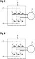
- FIG 3 shows a schematic representation of a control of the electrical machine 2 in an active short circuit according to a first embodiment.
- the upper three switching elements 10a, 10b and 10c are closed.
- the phase connections of the electrical machine 2 are thus electrically connected to one another via these three switching elements 10a-10c, that is to say short-circuited.
- Figure 4 shows an alternative schematic representation for an active short circuit according to a further embodiment.
- the lower switching elements 10d, 10e and 10f are closed, while the upper three switching elements 10a-10c are open.
- the phase connections of the electrical machine 2 are electrically connected to one another via the lower three switching elements 10d-10f and are therefore short-circuited.
- FIG. 5 shows a schematic representation of an electric drive device according to an embodiment of the present invention.
- the electrical drive device comprises an electrical machine 2.
- the electrical machine 2 can be one of the previously mentioned electrical machines, such as a synchronous machine, for example a permanently excited synchronous machine or alternatively also an asynchronous machine or the like.
- the three phase connections for connecting the electrical machine 2 to the inverter 1 are to be understood only as examples. Any other number of phase connections is also possible.
- the electrical machine 2 is controlled by an inverter 1.
- the inverter 1 provides a suitable AC voltage signal at the phase connections of the electrical machine 2. In this way, it is possible to operate the electrical machine 2 at a predetermined speed or a predetermined torque.
- the electrical machine 2 according to FIG Figure 3 or Figure 4 are put into the active short circuit by the inverter 1 and thus a safe state of the electrical machine 2 is established.
- phase connections of the electrical machine 2 are not immediately electrically connected to one another.
- the control device 11 of the inverter 1 detects a fault, or receives a request for an active short circuit via a further connection A
- the voltage at the phase connections of the electrical machine 2 is first continuously adjusted to a value which enables a change to the active short circuit without overcurrents occurring.
- this can be a previously defined voltage value, that is to say an AC voltage with a predetermined amplitude, to which the voltages at the phase connections of the electrical machine 2 are initially regulated.
- the voltage applied to the phase connections of the electrical machine 2 at the time of the request for an active short circuit is continuously reduced to a lower voltage value.
- the voltage at the phase connections of the electrical machine 2 is preferably reduced from the current value to 0 volts when the voltage is reduced.
- the amplitude of the AC voltage which is present at the phase connections of the electrical machine 2 at the start of the request for an active short circuit can be adjusted within a predetermined time interval to the predetermined value which is required for a change to the active short circuit.
- this time interval can be a time interval of a few milliseconds, for example 20 milliseconds, 10 milliseconds, 5 milliseconds or even just 1 millisecond. In this way it can be ensured that the active short circuit can actually be realized within a short time and that there are no major delays in setting a safe state, particularly in the event of an error.
- the change from the current phase voltage at the connections of the electrical machine 2 to the value for the change to the active state can also be carried out with a predetermined maximum slope. This means that the amplitude of the voltage present at the phase connections of the electrical machine 2 is changed by a predetermined value at most per unit of time. In this way it can be ensured that there are no disproportionately large voltage jumps when the electrical machine 2 is actuated.
- the change in the voltage ratios at the phase connections of the electrical machine 2 is preferably linear, that is, the amplitude of the voltage at the phase connections is carried out over the entire period with a constant voltage change per unit of time.
- alternative variations of the voltage values for setting the predetermined voltage for the change to the active short circuit are also possible.
- U d, init and U q, init are the two initial voltage values at the beginning of the request for an active short circuit and ⁇ t the time period during which the active short circuit is to be changed.
- the voltages at the phase connections of the electrical machine 2 are reduced from the initial values at the beginning of the request for an active short circuit to 0 volts when changing to the active short circuit, without this requiring a measurement of the phase currents.
- sensor values about the current state of the electrical drive device such as the phase currents or to allow the current voltage conditions on the electrical machine 2 to be incorporated into the control process.
- the electrical machine 2 must first be actively controlled by the inverter 1. During this activation of the electrical machine 2 by the inverter 1, the voltage at the phase connections of the electrical machine 2 can be reduced to a predetermined value, for example 0 volts, as already described above. In order not to cause voltage jumps at the beginning of this active control, when changing from free-wheeling operation to controlled operation, the electrical machine 2 is first controlled with a voltage that corresponds to the free-wheeling voltage of the electrical machine 2.
- the electrical drive device can have a voltage sensor 12 which measures the voltages at the phase connections of the electrical machine 2. The voltage values measured in this way are provided to the controller 11 of the inverter 1, whereupon the inverter 1 provides an AC voltage at the phase connections of the electrical machine 2 which corresponds to these voltage values.
- the current speed of the electrical machine 2 via a speed sensor 20 and to determine the current free-wheeling voltage of the electrical machine 2 from this.
- the relationships between the speed and the corresponding freewheeling voltage of the electrical machine 2 can be stored in a memory. After determining the current speed of the electrical machine 2, the corresponding freewheeling voltage can thus be read out from this memory and at the connections of the electrical machine can be set.
- Other options for determining or calculating the freewheeling voltage are also possible.
- a sensory measurement of the current speed of the electrical machine 2 it is also possible to determine the speed based on a model, estimated values or the last actively regulated speed. Other possibilities for determining the speed of the electrical machine 2 in the freewheel are also possible.
- the AC voltage provided by the inverter 1 at the phase connections of the electrical machine 2 is then continuously reduced to a predetermined value. If this predetermined value is reached, the inverter 1 then switches to the active short circuit, for example in accordance with Figure 3 or 4 .
- FIG. 6 shows a schematic illustration of a flowchart as it is based on a method 100 for operating an electrical machine 2.
- the electrical machine 2 In a control mode in which the electrical machine 2 is to be operated at a predetermined speed or a predetermined torque, the electrical machine 2 is controlled with a corresponding AC voltage. If an electrical machine 2 controlled in this way should switch to the active short circuit, the amplitude of the AC voltage at the connections of the electrical machine is set to a predetermined value after the occurrence of a corresponding event, for example the detection of a fault or a direct request for the active short circuit . This setting of the AC voltage to the predetermined value takes place on the basis of the voltage with which the electrical machine is controlled in control operation to the predetermined value within a predetermined time period or with a predetermined slope. After the predetermined value of the AC voltage has been set at the connections of the electrical machine, the connections of the electrical machine are electrically connected to one another in step 130 and thus short-circuited.
- step 105 If the electrical machine is operated in a free-wheeling mode in a step 105, in which the connections of the electrical machine are electrically separated from one another, it is first necessary to control the electrical machine in a defined manner. For this a free-wheeling voltage is determined in step 106, which corresponds to the voltage at the connections of the electrical machine in a free-wheeling mode. The electrical machine is then actuated with the determined freewheeling voltage in step 110 described above.
- the present invention relates to a method and a device for operating an electrical machine for a smooth change from a regulating or freewheeling operation to an active short circuit.
- a voltage with which the electrical machine is controlled is first regulated down to a predetermined, preferably very low value and only then short-circuited the phase connections of the electrical machine. In this way, disproportionately large overcurrents, in particular overcurrents that are greater than the nominal current of the electrical machine, can be avoided.
Landscapes
- Engineering & Computer Science (AREA)
- Power Engineering (AREA)
- Life Sciences & Earth Sciences (AREA)
- Sustainable Development (AREA)
- Sustainable Energy (AREA)
- Transportation (AREA)
- Mechanical Engineering (AREA)
- Control Of Ac Motors In General (AREA)
Description
Die vorliegende Erfindung betrifft eine Vorrichtung und ein Verfahren zum Betreiben einer elektrischen Maschine. Insbesondere betrifft die vorliegende Erfindung eine Vorrichtung und ein Verfahren zum Betreiben einer elektrischen Maschine bei dem Übergang der elektrischen Maschine in einen aktiven Kurzschlussbetrieb.The present invention relates to an apparatus and a method for operating an electrical machine. In particular, the present invention relates to a device and a method for operating an electrical machine during the transition of the electrical machine to an active short-circuit operation.
Elektrische Maschinen, wie zum Beispiel permanent erregte Synchronmaschinen, werden für zahlreiche technische Anwendungen eingesetzt. Beispielsweise können elektrische Maschinen als Antrieb für ein ganz oder teilweise elektrisch betriebenes Kraftfahrzeug verwendet werden. Aus Sicherheitsgründen müssen dabei Vorkehrungen für einen möglichen Fehlerfall getroffen werden. Ein solcher Fehlerfall kann beispielsweise eine Störung oder ein Ausfall eines Sensors sein, der Messwerte für einen sicheren Betrieb der elektrischen Maschine liefert. Ein weiterer Fehlerfall kann beispielsweise der Ausfall einer Versorgungsspannung in einem elektrisch betriebenen Kraftfahrzeug sein. Eine Möglichkeit für einen Betriebsmodus im Fehlerfall ist ein Freilaufbetrieb der elektrischen Maschine. Dabei wird die elektrische Maschine von außen nicht weiter mit einer elektrischen Spannung beaufschlagt. Die elektrischen Phasenanschlüsse der Maschine werden dabei voneinander getrennt. Ein weiterer sicherer Betriebsmodus ist der sogenannte aktive Kurzschluss. Bei diesem aktiven Kurzschluss werden durch geeignete Schaltelemente alle Phasenanschlüsse der Maschine elektrisch miteinander verbunden.Electrical machines, such as permanently excited synchronous machines, are used for numerous technical applications. For example, electrical machines can be used as a drive for a fully or partially electrically operated motor vehicle. For safety reasons, precautions must be taken for a possible fault. Such a fault can be, for example, a malfunction or a failure of a sensor that delivers measured values for the safe operation of the electrical machine. Another fault case can be, for example, the failure of a supply voltage in an electrically operated motor vehicle. One possibility for an operating mode in the event of a fault is free-running operation of the electrical machine. In this case, the electrical machine is no longer subjected to an electrical voltage. The electrical phase connections of the machine are separated from each other. Another safe operating mode is the so-called active short circuit. In the case of this active short circuit, all phase connections of the machine are electrically connected to one another by suitable switching elements.
Aus der Deutschen Patentanmeldung
Es besteht ein Bedarf nach einer Vorrichtung und einem Verfahren zum Betreiben einer elektrischen Maschine, die es ermöglichen, an der elektrischen Maschine sicher und schonend einen aktiven Kurzschlussbetrieb einzuleiten.There is a need for a device and a method for operating an electrical machine which enable active short-circuit operation to be initiated safely and gently on the electrical machine.
Hierzu schafft die vorliegende Erfindung eine Vorrichtung und ein Verfahren zum Betreiben einer elektrischen Maschine mit den Merkmalen der unabhängigen Patentansprüche.To this end, the present invention provides an apparatus and a method for operating an electrical machine with the features of the independent claims.
Der vorliegenden Erfindung liegt die Idee zugrunde, die elektrische Spannung an den Phasenanschlüssen einer elektrischen Maschine zunächst kontrolliert auf ein geeignetes Spannungsniveau abzusenken, bevor die elektrische Maschine in einen aktiven Kurzschluss geschaltet wird. Somit erfolgt der Übergang von einem aktuellen Betriebsmodus der elektrischen Maschine in den aktiven Kurzschluss nicht schlagartig, sondern unter geregelten Rahmenbedingungen. Durch diesen kontrollierten Übergang der elektrischen Spannung an den Phasenanschlüssen der elektrischen Maschine vor einem aktiven Kurzschluss ist es möglich, die Maschine in den aktiven Kurzschluss zu überführen, ohne dass sich hierbei ein zusätzlicher Überstrom einstellt.The present invention is based on the idea of first reducing the electrical voltage at the phase connections of an electrical machine in a controlled manner to a suitable voltage level before the electrical machine is switched into an active short circuit. Thus, the transition from a current operating mode of the electrical machine into the active short circuit does not occur suddenly, but under regulated framework conditions. This controlled transition of the electrical voltage at the phase connections of the electrical machine in front of you active short circuit, it is possible to convert the machine to the active short circuit without an additional overcurrent being established.
Diese Reduzierung des maximalen Stroms beim Übergang in den aktiven Kurzschluss ermöglicht es, sowohl die Ansteuerschaltung, als auch die elektrische Maschine selbst entsprechend effizienter zu dimensionieren. Darüber hinaus wird durch die Verringerung der maximal auftretenden Ströme auch die Lebensdauer der Ansteuerschaltung und der elektrischen Maschine erhöht und somit die Verfügbarkeit des Gesamtsystems gesteigert. Insbesondere kann die Gefahr, dass es aufgrund von zu hohen Überströmen bei dem Wechsel in den aktiven Kurzschluss in der elektrischen Maschine zu einer Entmagnetisierung der Magnete im Rotor der Maschine kommt, verringert werden. Auch sinkt die mechanische Belastung innerhalb der elektrischen Maschine und insbesondere in den Wicklungen der elektrischen Maschine bei einem erfindungsgemäßen Übergang in den aktiven Kurzschluss.This reduction in the maximum current during the transition to the active short circuit makes it possible to dimension both the control circuit and the electrical machine itself more efficiently. In addition, by reducing the maximum currents that occur, the service life of the control circuit and the electrical machine is also increased, and thus the availability of the overall system is increased. In particular, the risk of demagnetization of the magnets in the rotor of the machine due to excessive overcurrents when changing to the active short circuit in the electrical machine can be reduced. The mechanical load within the electrical machine and in particular in the windings of the electrical machine also decreases during a transition into the active short circuit according to the invention.
Gemäß einer Ausführungsform ist der Wechselrichter dazu ausgelegt, die Amplitude der an den Anschlüssen der elektrischen Maschine bereitgestellten Wechselspannung vor einem Übergang von dem gesteuerten Betrieb in den Kurzschlussbetrieb auf 0 Volt abzusenken. Alternativ kann die Spannung an den Phasenanschlüssen der elektrischen Maschine auf einen Wert von annähernd 0 Volt abgesenkt werden oder zumindest auf einen Wert reduziert werden, der kleiner ist als die Spannung an den Anschlüssen der elektrischen Maschine während des gesteuerten Betriebs. Durch ein solches Absenken der elektrischen Spannung an den Phasenanschlüssen der elektrischen Maschine vor dem Übergang in den aktiven Kurzschluss kann sichergestellt werden, dass es zu keinen gefährlichen Überströmen kommt, die zu Beschädigungen oder einer vorzeitigen Alterung der verwendeten Bauteile führen würde.According to one embodiment, the inverter is designed to reduce the amplitude of the AC voltage provided at the connections of the electrical machine to 0 volts before a transition from controlled operation to short-circuit operation. Alternatively, the voltage at the phase connections of the electrical machine can be reduced to a value of approximately 0 volts or at least reduced to a value which is less than the voltage at the connections of the electrical machine during the controlled operation. Such a lowering of the electrical voltage at the phase connections of the electrical machine before the transition to the active short circuit can ensure that there are no dangerous overcurrents that would lead to damage or premature aging of the components used.
Im Freilaufbetrieb wird die elektrische Maschine zunächst nicht aktiv angesteuert. Soll vom Freilaufbetrieb in den aktiven Kurzschluss gewechselt werden, so kann zur Vermeidung von unverhältnismäßig großen Überströmen daher zunächst die elektrische Maschine mit einer elektrischen Spannung angesteuert werden, die zumindest annähernd der aktuell an den Anschlüssen der elektrischen Maschine anliegenden Freilaufspannung entspricht. Daraufhin kann diese Spannung, mit der die elektrische Maschine dann angesteuert wird, aktiv auf den vorbestimmten Wert abgesenkt werden, der für einen schonenden Wechsel in den aktiven Kurzschluss erforderlich ist. Auf diese Weise ist auch ein schonender Übergang vom Freilaufbetrieb in den aktiven Kurzschluss möglich, ohne dass dabei gefährliche Überströme auftreten würden.In free-running mode, the electrical machine is initially not actively controlled. If a switch is to be made from the free-wheeling mode to the active short circuit, the electrical machine can therefore first be controlled with an electrical voltage which at least approximately corresponds to the free-wheeling voltage currently present at the connections of the electrical machine to avoid disproportionately large overcurrents. Thereupon this voltage, with which the electrical machine is then controlled, can be actively reduced to the predetermined value which is required for a gentle change into the active short circuit. That way too a gentle transition from freewheeling operation to active short-circuit is possible without dangerous overcurrents occurring.
Da die Freilaufspannung in der Regel eine von der Drehzahl der elektrischen Maschine abhängige Funktion darstellt, kann auch in diesem Fall eine effiziente Bestimmung der Freilaufspannung an der elektrischen Maschine ermöglicht werden, so dass es auch beim Ansteuern der elektrischen Maschine mit der Freilaufspannung zu keinen größeren Diskrepanzen zwischen der von dem Wechselrichter bereitgestellten Spannung und der tatsächlichen Freilaufspannung kommt.Since the freewheel voltage generally represents a function dependent on the speed of the electrical machine, an efficient determination of the freewheel voltage on the electrical machine can also be made possible in this case, so that there are no major discrepancies when the electrical machine is actuated with the freewheel voltage comes between the voltage provided by the inverter and the actual freewheeling voltage.
Zusätzlich oder alternativ kann die Vorrichtung zum Betreiben der elektrischen Maschine auch über einen Spannungssensor verfügen, der die elektrische Spannung an den Anschlüssen der Maschine erfasst, wobei der dem Wechselrichter bei einem Übergang von dem Freilaufbetrieb in den Kurzschlussbetrieb zunächst die von dem Sensor erfasste Freilaufspannung einstellt. Anschließend kann dann ausgehend von dieser Spannung die Ansteuerung auf die für den Wechsel in den aktiven Kurzschluss erforderliche Spannung angepasst werden.Additionally or alternatively, the device for operating the electrical machine can also have a voltage sensor that detects the electrical voltage at the connections of the machine, with the inverter initially setting the freewheeling voltage detected by the sensor during a transition from freewheeling operation to short-circuiting operation. Based on this voltage, the control can then be adapted to the voltage required for the change to the active short circuit.
Gemäß einem Ausführungsbeispiel ist der Wechselrichter dazu ausgelegt, die Amplitude der Wechselspannung nach Beendigung des gesteuerten Betriebs innerhalb einer vorbestimmten Zeitdauer auf den vorbestimmten Wert einzustellen. Auf diese Weise kann die Zeitspanne innerhalb derer der Übergang von dem gesteuerten Betrieb in den Kurzschlussbetrieb erfolgt, vorgegeben werden. Somit ist auch sichergestellt, dass es zu keiner unverhältnismäßigen Verzögerung bei der Aktivierung des aktiven Kurzschlusses kommt.According to one exemplary embodiment, the inverter is designed to set the amplitude of the AC voltage to the predetermined value within a predetermined time period after the controlled operation has ended. In this way, the time period within which the transition from the controlled operation to the short-circuit operation takes place can be predetermined. This also ensures that there is no disproportionate delay in activating the active short circuit.
Alternativ ist es auch möglich, dass der Wechselrichter bei einem Übergang von dem gesteuerten Betrieb zu dem Kurzschlussbetrieb die Amplitude der an den Anschlüssen der elektrischen Maschine bereitgestellten Wechselspannung mit einer vorbestimmten Steilheit, das heißt mit einer vorbestimmten Spannungsdifferenz pro Zeiteinheit einstellt. Auf diese Weise kann sichergestellt werden, dass es zu keinen unverhältnismäßig großen Veränderungen in den Spannungsverhältnissen kommt.Alternatively, it is also possible for the inverter to set the amplitude of the AC voltage provided at the connections of the electrical machine with a predetermined slope, that is to say with a predetermined voltage difference per unit of time, during a transition from the controlled operation to the short-circuit operation. In this way it can be ensured that there are no disproportionately large changes in the tension.
Die vorliegende Erfindung betrifft ferner eine elektrische Antriebsvorrichtung mit einer elektrischen Maschine und einer erfindungsgemäßen Vorrichtung zum Betreiben einer elektrischen Maschine.The present invention further relates to an electrical drive device with an electrical machine and a device according to the invention for operating an electrical machine.
Gemäß einem Ausführungsbeispiel umfasst die elektrische Maschine dabei eine permanent erregte Synchronmaschine.According to one exemplary embodiment, the electrical machine comprises a permanently excited synchronous machine.
Ferner betrifft die vorliegende Erfindung ein Kraftfahrzeug mit einer elektrischen Maschine, die von einer erfindungsgemäßen Vorrichtung zum Betreiben der elektrischen Maschine angesteuert wird.Furthermore, the present invention relates to a motor vehicle with an electrical machine which is controlled by a device according to the invention for operating the electrical machine.
Weitere Ausführungsformen und Vorteile der vorliegenden Erfindung ergeben sich aus der nachfolgenden Beschreibung unter Bezug auf die beigefügten Figuren.Further embodiments and advantages of the present invention result from the following description with reference to the attached figures.
Dabei zeigen:
- Figur 1:
- eine schematische Darstellung einer elektrischen Antriebsvorrichtung;
- Figur 2:
- eine schematische Darstellung einer elektrischen Antriebsvorrichtung im Freilaufbetrieb;
- Figur 3:
- eine schematische Darstellung einer elektrischen Antriebsvorrichtung in einem aktiven Kurzschlussbetrieb gemäß einer Ausführungsform;
- Figur 4:
- eine schematische Darstellung einer elektrischen Antriebsvorrichtung in einem aktiven Kurzschlussbetrieb gemäß einer weiteren Ausführungsform;
- Figur 5:
- eine schematische Darstellung eines elektrischen Antriebssystems gemäß einer weiteren Ausführungsform der vorliegenden Erfindung; und
- Figur 6:
- eine schematische Darstellung eines Ablaufdiagramms für ein Verfahren wie es einer weiteren Ausführungsform zugrunde liegt.
- Figure 1:
- a schematic representation of an electric drive device;
- Figure 2:
- a schematic representation of an electric drive device in freewheeling operation;
- Figure 3:
- a schematic representation of an electric drive device in an active short-circuit operation according to an embodiment;
- Figure 4:
- a schematic representation of an electric drive device in an active short-circuit operation according to a further embodiment;
- Figure 5:
- a schematic representation of an electric drive system according to a further embodiment of the present invention; and
- Figure 6:
- is a schematic representation of a flow chart for a method as it is based on another embodiment.
In einem gesteuerten Betrieb konvertiert der Wechselrichter 1 die an dem Eingang bereitgestellte elektrische Energie in eine geeignete Wechselspannung und stellt diese an den Phasenanschlüssen der elektrischen Maschine 2 bereit. In einem Regelbetrieb kann dabei die bereitgestellte elektrische Wechselspannung an den Anschlüssen der elektrischen Maschine 2 so eingestellt werden, dass eine gewünschte Drehzahl oder ein gewünschtes Drehmoment durch die elektrische Maschine 2 erzielt wird. Hierzu kann das elektrische Antriebssystem ferner auch über einen oder mehrere Sensoren (nicht dargestellt) verfügen, die zum Beispiel die aktuelle Drehzahl, Spannungsverhältnisse oder Phasenströme innerhalb des elektrischen Antriebssystems ermitteln. Diese Sensorwerte können dann von einer Regelung ausgewertet werden und daraufhin basierend auf den vorgegebenen Sollwerten die Ansteuerung des Wechselrichters 1 angepasst werden.In a controlled operation, the
In den hier dargestellten Ausführungsbeispielen handelt es sich bei der elektrischen Maschine 2 um einen dreiphasigen Elektromotor. Darüber hinaus sind auch elektrische Maschinen mit einer anderen Anzahl von Phasenanschlüssen ebenso möglich. Bei der elektrischen Maschine 2 kann es sich beispielsweise um eine Synchronmaschine, vorzugsweise um eine permanent erregte Synchronmaschine handeln. Aber auch andere elektrische Maschinen, wie zum Beispiel eine Asynchronmaschine, etc. sind darüber hinaus ebenso möglich.In the exemplary embodiments shown here, the
Der Wechselrichter 1 umfasst dabei mehrere Schaltelemente 10a-10f. Durch geeignetes Ansteuern dieser Schaltelemente 10a-10f kann der Wechselrichter 1 somit aus der am Eingang bereitgestellten Spannung eine Wechselspannung konvertieren, die an den Anschlüssen der elektrischen Maschine 2 bereitgestellt wird. Entsprechend der Ansteuerung der einzelnen Schaltelemente 10a-10f kann beispielsweise durch geeignetes Pulsen dieser Schaltelemente 10a-10f eine Wechselspannung mit einer vorgegebenen Amplitude generiert werden. Dabei kann die Amplitude der so erzeugten Wechselspannung in Abhängigkeit eines zu erzielenden Drehmoments bzw. einer zu erzielenden Drehzahl der elektrischen Maschine 2 angepasst werden.The
Vorzugsweise handelt es sich bei den Schaltelementen 10a-10f um Halbleiterschaltelemente, wie zum Beispiel IGBT oder MOSFET. Parallel zu jedem dieser Schaltelemente 10a-10f kann darüber hinaus eine Freilaufdiode angeordnet werden. Durch diese Freilaufdiode kann bei geöffnetem Halbleiterschalter gegebenenfalls ein durch die elektrische Maschine 2 getriebener Strom fließen.The
Die elektrische Maschine 2 wird, wie bereits zuvor beschrieben, von einem Wechselrichter 1 angesteuert. In einem Regelbetrieb stellt der Wechselrichter 1 dabei an den Phasenanschlüssen der elektrischen Maschine 2 jeweils ein geeignetes Wechselspannungssignal bereit. Auf diese Weise ist es möglich, die elektrische Maschine 2 mit einer vorgegebenen Drehzahl oder einem vorgegebenen Drehmoment zu betreiben.As already described above, the
Kommt es während des Betriebs des elektrischen Antriebs zu einem Fehlerfall, so kann es dabei erforderlich sein, die Phasenanschlüsse der elektrischen Maschine 2 untereinander kurzzuschließen. Hierzu kann die elektrische Maschine 2 gemäß
Wird durch eine Steuervorrichtung 11 des Wechselrichters 1 oder auch über eine externe Kontroll- und/oder Steuervorrichtung (hier nicht dargestellt) ein solcher Fehlerfall erkannt, der einen aktiven Kurzschluss erfordert, so werden die Phasenanschlüsse der elektrischen Maschine 2 nicht unmittelbar sofort miteinander elektrisch verbunden. Sobald die Steuervorrichtung 11 des Wechselrichters 1 einen Fehlerfall detektiert, oder über einen weiteren Anschluss A eine Anforderung für einen aktiven Kurzschluss erhält, wird die Spannung an den Phasenanschlüssen der elektrischen Maschine 2 zunächst kontinuierlich auf einen Wert angepasst, der einen Wechsel in den aktiven Kurzschluss ermöglicht, ohne dass dabei Überströme auftreten. Beispielsweise kann es sich dabei um einen zuvor definierten Spannungswert, also um eine Wechselspannung mit einer vorbestimmten Amplitude, handeln, auf den die Spannungen an den Phasenanschlüssen der elektrischen Maschine 2 zunächst eingeregelt werden. In der Regel wird dabei die zum Zeitpunkt der Anforderung für einen aktiven Kurzschluss an den Phasenanschlüssen der elektrischen Maschine 2 anliegende Spannung auf einen geringeren Spannungswert kontinuierlich abgesenkt.If such a fault is recognized by a
Da bei einem aktiven Kurzschluss der elektrischen Maschine 2 die Phasenanschlüsse der elektrischen Maschine 2 kurzgeschlossen sind, wird bei diesem Absenken der Spannung an den Phasenanschlüssen der elektrischen Maschine 2 die Spannung vorzugsweise von dem aktuellen Wert auf 0 Volt heruntergeregelt. Es ist jedoch auch möglich, die Spannung an den Phasenanschlüssen der elektrischen Maschine 2 nicht vollständig auf 0 Volt herunter zu regeln, sondern die Phasenspannungen nur auf einen vorgegebenen Wert abzusenken und daraufhin durch den Wechselrichter 1 die Phasenanschlüsse der elektrischen Maschine 2 untereinander kurzzuschließen.Since the phase connections of the
Die Amplitude der Wechselspannung, die zum Beginn der Anforderung für einen aktiven Kurzschluss an den Phasenanschlüssen der elektrischen Maschine 2 anliegt, kann dabei innerhalb eines vorbestimmten Zeitintervalls auf den vorbestimmten Wert angepasst werden, der für einen Wechsel in den aktiven Kurzschluss erforderlich ist. Beispielsweise kann es sich bei diesem Zeitintervall um ein Zeitintervall von wenigen Millisekunden, beispielsweise 20 Millisekunden, 10 Millisekunden, 5 Millisekunden oder auch nur 1 Millisekunde handeln. Auf diese Weise kann sichergestellt werden, dass der aktive Kurzschluss auch innerhalb kurzer Zeit tatsächlich realisiert werden kann und es gerade im Fehlerfall zu keinen größeren Verzögerungen für das Einstellen eines sicheren Zustandes kommt.The amplitude of the AC voltage which is present at the phase connections of the
Alternativ kann der Wechsel von der aktuellen Phasenspannung an den Anschlüssen der elektrischen Maschine 2 auf den Wert für den Wechsel in den aktiven Zustand auch mit einer vorgegebenen maximalen Steilheit ausgeführt werden. Das heißt, die Amplitude der an den Phasenanschlüssen der elektrischen Maschine 2 anliegenden Spannung wird dabei pro Zeiteinheit maximal um einen vorgegebenen Wert verändert. Auf diese Weise kann gewährleistet werden, dass es zu keinen unverhältnismäßig großen Spannungssprüngen bei der Ansteuerung der elektrischen Maschine 2 kommt.Alternatively, the change from the current phase voltage at the connections of the
Die Änderung der Spannungsverhältnisse an den Phasenanschlüssen der elektrischen Maschine 2 erfolgt dabei vorzugsweise linear, das heißt die Amplitude der Spannung an den Phasenanschlüssen wird über den gesamten Zeitraum mit einer konstanten Spannungsänderung pro Zeiteinheit ausgeführt. Aber auch alternative Variationen der Spannungswerte zum Einstellen der vorgegebenen Spannung für den Wechsel in den aktiven Kurzschluss sind ebenso möglich.The change in the voltage ratios at the phase connections of the
Werden während des Übergangs in den aktiven Kurzschluss die Spannungen an den Phasenanschlüssen der elektrischen Maschine 2 über die Stellgrößen einer d-q-Regelung vorgenommen, so können die Komponenten der beiden Spannungen Ud(t) und Uq(t) wie folgt geregelt werden: ![]()
![]()
![]()
![]()
Dabei sind Ud,init und Uq,init jeweils die beiden initialen Spannungswerte zu Beginn der Anforderung für einen aktiven Kurzschluss und Δt die Zeitspanne während der in den aktiven Kurzschluss gewechselt werden soll.U d, init and U q, init are the two initial voltage values at the beginning of the request for an active short circuit and Δt the time period during which the active short circuit is to be changed.
In diesem Fall erfolgt die Absenkung der Spannungen an den Phasenanschlüssen der elektrischen Maschine 2 von den initialen Werten zu Beginn der Anforderung für einen aktiven Kurzschluss auf 0 Volt beim Wechsel in den aktiven Kurzschluss, ohne dass hierzu eine Messung der Phasenströme erforderlich wäre.In this case, the voltages at the phase connections of the
Alternativ ist es jedoch auch möglich, sofern verfügbar, Sensorwerte über den aktuellen Zustand der elektrischen Antriebsvorrichtung, wie beispielsweise die Phasenströme oder die aktuellen Spannungsverhältnisse an der elektrischen Maschine 2 mit in den Regelprozess einfließen zu lassen.Alternatively, however, it is also possible, if available, sensor values about the current state of the electrical drive device, such as the phase currents or to allow the current voltage conditions on the
In dem zuvor beschriebenen Übergang von einem Regelbetrieb, bei dem die elektrische Maschine durch den Wechselrichter 1 aktiv mit Spannungen beaufschlagt wird, in den aktiven Kurzschluss, ist es darüber hinaus auch möglich, die elektrische Maschine aus dem Freilaufbetrieb ebenfalls in den aktiven Kurzschluss zu überführen, ohne dass hierbei gefährliche Überströme auftreten. Befindet sich der elektrische Antrieb im Freilaufbetrieb, das heißt alle Schaltelemente 10a-10f des Wechselrichters 1 sind geöffnet und die elektrischen Phasenanschlüsse sind voneinander elektrisch getrennt, so stellt sich an diesen Phasenanschlüssen jeweils eine elektrische Wechselspannung ein, die zu diesem Zeitpunkt nicht durch den Wechselrichter 1 beeinflusst wird.In the previously described transition from a control mode, in which voltages are actively applied to the electrical machine by the
Soll aus diesem Freilaufbetrieb in den aktiven Kurzschluss gewechselt werden, so muss dabei zunächst die elektrische Maschine 2 durch den Wechselrichter 1 aktiv angesteuert werden. Während dieser Ansteuerung der elektrischen Maschine 2 durch den Wechselrichter 1 kann dabei die Spannung an den Phasenanschlüssen der elektrischen Maschine 2 wie bereits zuvor beschrieben auf einen vorbestimmten Wert, beispielsweise 0 Volt abgesenkt werden. Um zu Beginn dieser aktiven Ansteuerung keine Spannungssprünge zu verursachen, wird beim Wechsel vom Freilaufbetrieb in den gesteuerten Betrieb die elektrische Maschine 2 zunächst mit einer Spannung angesteuert, die der Freilaufspannung der elektrischen Maschine 2 entspricht. Beispielsweise kann die elektrische Antriebsvorrichtung hierzu einen Spannungssensor 12 aufweisen, der die Spannungen an den Phasenanschlüssen der elektrischen Maschine 2 misst. Die so gemessenen Spannungswerte werden dem Regler 11 des Wechselrichters 1 bereitgestellt, worauf der Wechselrichter 1 an den Phasenanschlüssen der elektrischen Maschine 2 eine Wechselspannung bereitgestellt, die diesen Spannungswerten entspricht.If it is desired to switch from this freewheeling operation to the active short circuit, the
Alternativ ist es auch möglich, über einen Drehzahlsensor 20 die aktuelle Drehzahl der elektrischen Maschine 2 zu erfassen und hieraus die aktuelle Freilaufspannung der elektrischen Maschine 2 zu bestimmen. Beispielsweise können die Beziehungen zwischen Drehzahl und korrespondierender Freilaufspannung der elektrischen Maschine 2 in einem Speicher abgelegt werden. Nach dem Bestimmen der aktuellen Drehzahl der elektrischen Maschine 2 kann somit aus diesem Speicher die korrespondierende Freilaufspannung ausgelesen und an den Anschlüssen der elektrischen Maschine eingestellt werden. Alternativ ist es auch möglich, eine mathematische Beziehung zwischen Freilaufspannung und Drehzahl zu definieren und basierend aus der erfassten Drehzahl der elektrischen Maschine 2 die Freilaufspannung zu bestimmen. Weitere Möglichkeiten zur Bestimmung bzw. Berechnung der Freilaufspannung sind ebenso möglich. Neben einer sensorischen Messung der aktuellen Drehzahl der elektrischen Maschine 2 ist es auch möglich, die Drehzahl basierend auf einem Modell, Schätzwerten oder der zuletzt aktiv eingeregelten Drehzahl zu bestimmen. Weitere Möglichkeiten zur Bestimmung der Drehzahl der elektrischen Maschine 2 im Freilauf sind ebenso möglich.Alternatively, it is also possible to detect the current speed of the
Nachdem zunächst durch den Wechselrichter 1 an den Phasenanschlüssen der elektrischen Maschine 2 die Freilaufspannung eingestellt worden ist, wird anschließend die durch den Wechselrichter 1 bereitgestellte Wechselspannung an den Phasenanschlüssen der elektrischen Maschine 2 kontinuierlich auf einen vorbestimmten Wert abgesenkt. Ist dieser vorbestimmte Wert erreicht, so schaltet der Wechselrichter 1 daraufhin in den aktiven Kurzschluss, beispielsweise gemäß
Wird die elektrische Maschine in einem Schritt 105 in einem Freilaufbetrieb betrieben, bei dem die Anschlüsse der elektrischen Maschine voneinander elektrisch getrennt sind, so ist es dabei zunächst erforderlich, die elektrische Maschine definiert anzusteuern. Hierzu wird in Schritt 106 eine Freilaufspannung ermittelt, die der Spannung an den Anschlüssen der elektrischen Maschine in einem Freilaufbetrieb entspricht. Daraufhin erfolgt in dem zuvor beschriebenen Schritt 110 die Ansteuerung der elektrischen Maschine mit der ermittelten Freilaufspannung.If the electrical machine is operated in a free-wheeling mode in a
Zusammenfassend betrifft die vorliegende Erfindung ein Verfahren und eine Vorrichtung zum Betreiben einer elektrischen Maschine für einen sanften Wechsel von einem Regel- oder Freilaufbetrieb in einen aktiven Kurzschluss. Hierzu wird eine Spannung, mit der die elektrische Maschine angesteuert wird, zunächst definiert auf einen vorgegebenen, vorzugsweise sehr geringen Wert heruntergeregelt und anschließend erst die Phasenanschlüsse der elektrischen Maschine kurzgeschlossen. Somit können unverhältnismäßig große Überströme, insbesondere Überströme, die größer als der Nennstrom der elektrischen Maschine sind, vermieden werden.In summary, the present invention relates to a method and a device for operating an electrical machine for a smooth change from a regulating or freewheeling operation to an active short circuit. For this purpose, a voltage with which the electrical machine is controlled is first regulated down to a predetermined, preferably very low value and only then short-circuited the phase connections of the electrical machine. In this way, disproportionately large overcurrents, in particular overcurrents that are greater than the nominal current of the electrical machine, can be avoided.
Claims (7)
- Device for operating an electrical machine (2), having
an inverter (1) that comprises a multiplicity of switching elements (10a-10f) and that is designed to provide an AC voltage at the terminals of the electrical machine (2) by driving the switching elements (10a-10f) in a controlled mode, to electrically disconnect the terminals of the electrical machine (2) from one another in a freewheeling mode and to electrically connect the terminals of the electrical machine (2) to one another in a short-circuit mode, and
a rotational speed sensor (20) that is designed to determine the rotational speed of the electrical machine (2),
wherein the inverter (1) is designed, in the event of a transition from the controlled mode to the short-circuit mode, to set the amplitude of the AC voltage provided at the terminals of the electrical machine (2) to a predetermined value; and
wherein the inverter (1) is designed, in the event of a transition from the freewheeling mode to the short-circuit mode, to first of all determine a rotational speed-dependent freewheeling voltage and to provide the determined rotational speed-dependent freewheeling voltage at the terminals of the electrical machine (2). - Device according to Claim 1, wherein the inverter (1) is designed to reduce the amplitude of the AC voltage provided at the terminals of the electrical machine (2) to 0 volt prior to a transition from the controlled mode to the short-circuit mode by driving the switching elements (10a-10f).
- Device according to Claim 1 or 2, wherein the inverter (1) is designed to set the amplitude of the AC voltage to the predetermined value within a predetermined time interval.
- Electrical drive device, having:an electrical machine (2); anda device according to one of Claims 1 to 3.
- Electrical drive device according to Claim 4, wherein the electrical machine (2) comprises a permanently excited synchronous machine.
- Motor vehicle having an electrical machine (2) that is driven by a device according to one of Claims 1 to 3.
- Method (100) for operating an electrical machine (2), having the steps of:operating (105) an electrical machine (2) in a freewheeling mode, wherein the terminals of the electrical machine (2) are electrically disconnected from one another;recording a current rotational speed of the electrical machine (2) using a rotational speed sensor;determining (106) a rotational speed-dependent freewheeling voltage that corresponds to the voltage at the terminals of the electrical machine (2) in the freewheeling mode, based on the determined current rotational speed of the electrical machine (2);driving (110) the terminals of the electrical machine (2) with the determined freewheeling voltage in a controlled mode;setting (120) the amplitude of the AC voltage with which the electrical machine (2) is driven to a predetermined value; andelectrically connecting (130) the terminals of the electrical machine (2) after the amplitude of the AC voltage has been set to the predetermined value, in a short-circuit mode.
Applications Claiming Priority (2)
| Application Number | Priority Date | Filing Date | Title |
|---|---|---|---|
| DE102013226564.6A DE102013226564A1 (en) | 2013-12-19 | 2013-12-19 | Apparatus and method for operating an electrical machine |
| PCT/EP2014/074588 WO2015090754A1 (en) | 2013-12-19 | 2014-11-14 | Device and method for operating an electric machine |
Publications (2)
| Publication Number | Publication Date |
|---|---|
| EP3083320A1 EP3083320A1 (en) | 2016-10-26 |
| EP3083320B1 true EP3083320B1 (en) | 2020-08-05 |
Family
ID=51903899
Family Applications (1)
| Application Number | Title | Priority Date | Filing Date |
|---|---|---|---|
| EP14799409.9A Active EP3083320B1 (en) | 2013-12-19 | 2014-11-14 | Apparatus and method for operating an electric machine |
Country Status (5)
| Country | Link |
|---|---|
| US (1) | US9825576B2 (en) |
| EP (1) | EP3083320B1 (en) |
| CN (1) | CN105813882B (en) |
| DE (1) | DE102013226564A1 (en) |
| WO (1) | WO2015090754A1 (en) |
Cited By (1)
| Publication number | Priority date | Publication date | Assignee | Title |
|---|---|---|---|---|
| WO2023041220A1 (en) | 2021-09-17 | 2023-03-23 | Robert Bosch Gmbh | Device and method for operating an electric machine |
Families Citing this family (13)
| Publication number | Priority date | Publication date | Assignee | Title |
|---|---|---|---|---|
| JP6740657B2 (en) * | 2016-03-23 | 2020-08-19 | アイシン・エィ・ダブリュ株式会社 | Inverter device |
| DE102017207886A1 (en) * | 2016-06-03 | 2017-12-07 | Robert Bosch Engineering And Business Solutions Private Limited | Control unit and method for driving an inverter circuit for a permanent magnet synchronous motor |
| FR3097699B1 (en) * | 2019-06-18 | 2021-07-16 | Alstom Transp Tech | Method of inhibiting an inverter of an electric power supply chain of a permanent magnet motor |
| GB2592180B (en) | 2019-10-08 | 2022-02-23 | Borgwarner Gateshead Ltd | Method and apparatus for controlling electric motors |
| GB2593157B (en) * | 2020-03-11 | 2022-06-08 | Protean Electric Ltd | A circuit for an inverter |
| DE102020112940A1 (en) | 2020-05-13 | 2021-11-18 | Dr. Ing. H.C. F. Porsche Aktiengesellschaft | Method and device for operating a synchronous machine |
| FR3115944A1 (en) * | 2020-11-03 | 2022-05-06 | Nidec Psa Emotors | Method for controlling an inverter and corresponding system |
| DE102020215125A1 (en) | 2020-12-01 | 2022-06-02 | Robert Bosch Gesellschaft mit beschränkter Haftung | Method for operating an electrical machine, device for operating an electrical machine, electrical drive system |
| CN112787568A (en) * | 2021-01-04 | 2021-05-11 | 无锡华宸控制技术有限公司 | Method for active short circuit control of motor |
| DE102021201858A1 (en) | 2021-02-26 | 2022-09-01 | Vitesco Technologies Germany Gmbh | Method and control unit for switching an electric drive between an operating mode with an active short circuit and a freewheeling operating mode |
| DE102022202956B4 (en) * | 2022-03-25 | 2023-11-16 | Vitesco Technologies Germany Gmbh | Hysteresis-based control of a vehicle drive with alternating freewheeling and short-circuit states in the event of a fault |
| DE102023115444A1 (en) * | 2023-06-14 | 2024-12-19 | Bayerische Motoren Werke Aktiengesellschaft | Method and device for the safe operation of an electrical machine |
| CN119396061B (en) * | 2024-12-30 | 2025-04-29 | 杭州海康威视数字技术股份有限公司 | Barrier gate control circuit and barrier gate control method |
Family Cites Families (15)
| Publication number | Priority date | Publication date | Assignee | Title |
|---|---|---|---|---|
| CN87216123U (en) * | 1987-12-09 | 1988-08-10 | 保定市三丰电器厂 | Analog-rectifier relay protection unit |
| JPH0984208A (en) * | 1995-09-14 | 1997-03-28 | Denso Corp | Electric car controller |
| US5874818A (en) * | 1997-06-11 | 1999-02-23 | Agile Systems, Inc. | Method and apparatus for sensing load current in a motor controller |
| DE10146527A1 (en) * | 2001-09-21 | 2003-04-24 | Siemens Ag | Converter with a line and load side self-commutated pulse converter |
| GB2413905B (en) * | 2004-05-05 | 2006-05-03 | Imra Europ S A S Uk Res Ct | Permanent magnet synchronous motor and controller therefor |
| DE102006003254A1 (en) * | 2006-01-24 | 2007-07-26 | Robert Bosch Gmbh | Operating method for electrical machine with pulse-controlled inverter in case of disturbance, involves switching electrical machine into de-energizing mode and into short-circuit mode |
| JP4085112B2 (en) * | 2006-01-31 | 2008-05-14 | ファナック株式会社 | Motor control method and motor control apparatus |
| US7279862B1 (en) * | 2006-08-04 | 2007-10-09 | Gm Global Technology Operations, Inc. | Fault handling of inverter driven PM motor drives |
| US7489097B2 (en) * | 2006-11-02 | 2009-02-10 | Chrysler Llc | Sensorless position detection for a brushless direct current motor during inverter standby |
| DE102007020509A1 (en) * | 2007-05-02 | 2008-11-06 | Robert Bosch Gmbh | Error treatment in an electric machine of a hybrid drive |
| JP5003589B2 (en) * | 2008-05-15 | 2012-08-15 | トヨタ自動車株式会社 | Short-circuit phase identification method |
| US8319460B2 (en) * | 2009-10-27 | 2012-11-27 | GM Global Technology Operations LLC | Method and system for initiating operation of an electric motor |
| CN101850723B (en) * | 2010-04-30 | 2012-07-25 | 锦州海伯伦汽车电子有限公司 | Fault detecting and processing method for current sensor of motor control unit of electric automobile |
| DE102012002023A1 (en) | 2011-06-21 | 2012-12-27 | Volkswagen Aktiengesellschaft | Method for operating inverter circuit of permanent magnet synchronous electric machine e.g. electric motor, involves operating electric machine in active short-circuit mode, when rotational speed is above threshold value |
| DE102012101508A1 (en) | 2012-02-24 | 2013-08-29 | Volkswagen Aktiengesellschaft | Method for operating e.g. permanently excited synchronous machine for motor car, involves comparing voltage in intermediate circuit with minimum limit voltage value in circuit, to open converter valves so as to drive machine |
-
2013
- 2013-12-19 DE DE102013226564.6A patent/DE102013226564A1/en active Pending
-
2014
- 2014-11-14 EP EP14799409.9A patent/EP3083320B1/en active Active
- 2014-11-14 US US15/104,583 patent/US9825576B2/en active Active
- 2014-11-14 CN CN201480069061.1A patent/CN105813882B/en active Active
- 2014-11-14 WO PCT/EP2014/074588 patent/WO2015090754A1/en not_active Ceased
Non-Patent Citations (1)
| Title |
|---|
| None * |
Cited By (2)
| Publication number | Priority date | Publication date | Assignee | Title |
|---|---|---|---|---|
| WO2023041220A1 (en) | 2021-09-17 | 2023-03-23 | Robert Bosch Gmbh | Device and method for operating an electric machine |
| DE102021210336A1 (en) | 2021-09-17 | 2023-04-13 | Robert Bosch Gesellschaft mit beschränkter Haftung | Device and method for operating an electrical machine |
Also Published As
| Publication number | Publication date |
|---|---|
| US9825576B2 (en) | 2017-11-21 |
| CN105813882B (en) | 2018-02-09 |
| DE102013226564A1 (en) | 2015-06-25 |
| EP3083320A1 (en) | 2016-10-26 |
| WO2015090754A1 (en) | 2015-06-25 |
| CN105813882A (en) | 2016-07-27 |
| US20160322927A1 (en) | 2016-11-03 |
Similar Documents
| Publication | Publication Date | Title |
|---|---|---|
| EP3083320B1 (en) | Apparatus and method for operating an electric machine | |
| EP3083321B1 (en) | Apparatus and method for operating an electric machine | |
| EP2548757B1 (en) | Drive system and method for operating such a drive system | |
| DE102012101508A1 (en) | Method for operating e.g. permanently excited synchronous machine for motor car, involves comparing voltage in intermediate circuit with minimum limit voltage value in circuit, to open converter valves so as to drive machine | |
| WO2005048446A1 (en) | Braking method for a synchronous machine | |
| DE112014002475T5 (en) | Inverter device | |
| WO2017186393A1 (en) | Method and device for determining a capacitance of a dc link capacitor | |
| EP3058652B1 (en) | Control unit with safety shutdown | |
| WO2016128194A1 (en) | Method for operating an active converter connected to an electrical machine and means for the implementation thereof | |
| EP3545617B1 (en) | Protective device for an electric drive system, electric drive system, and method for operating an electric drive system | |
| WO2011018302A1 (en) | Method for monitoring a drive state of an electric motor | |
| WO2017016747A1 (en) | Method and device for operating an electric system | |
| EP3257134B1 (en) | Method for operating an active converter connected to an electric maschine and device for its implementation | |
| EP4256691B1 (en) | Method for operating an electric machine, device for operating an electric machine, and electric drive system | |
| WO2005008877A1 (en) | Monitoring circuit for an electric motor and method for monitoring an electric motor | |
| EP3519241A1 (en) | Converter, electrical drive system, and method for charging an electrical energy store | |
| EP3520196B1 (en) | Voltage controller of a generator | |
| EP3083319B1 (en) | Apparatus and method for operating an electric machine | |
| DE102015003446A1 (en) | Supply of a motor vehicle with voltage test | |
| EP4396021A1 (en) | Method for operating an electric drive system, computer program product, data carrier and electric drive system | |
| EP3075593B1 (en) | Method for discharging an electrical energy store of a motor vehicle | |
| DE102016215237A1 (en) | Operating a generator controller | |
| EP3172831A1 (en) | Method for operating an at least generator-operable electric machine and means for the implementation thereof | |
| DE102015202912B3 (en) | Method and device for driving an active bridge rectifier when canceling a phase short circuit | |
| WO2025045946A1 (en) | Method for operating a brushless electric motor having improved emergency switch-off |
Legal Events
| Date | Code | Title | Description |
|---|---|---|---|
| PUAI | Public reference made under article 153(3) epc to a published international application that has entered the european phase |
Free format text: ORIGINAL CODE: 0009012 |
|
| 17P | Request for examination filed |
Effective date: 20160719 |
|
| AK | Designated contracting states |
Kind code of ref document: A1 Designated state(s): AL AT BE BG CH CY CZ DE DK EE ES FI FR GB GR HR HU IE IS IT LI LT LU LV MC MK MT NL NO PL PT RO RS SE SI SK SM TR |
|
| AX | Request for extension of the european patent |
Extension state: BA ME |
|
| DAX | Request for extension of the european patent (deleted) | ||
| REG | Reference to a national code |
Ref country code: DE Ref legal event code: R079 Ref document number: 502014014587 Country of ref document: DE Free format text: PREVIOUS MAIN CLASS: B60L0003040000 Ipc: H02P0029024000 |
|
| GRAP | Despatch of communication of intention to grant a patent |
Free format text: ORIGINAL CODE: EPIDOSNIGR1 |
|
| STAA | Information on the status of an ep patent application or granted ep patent |
Free format text: STATUS: GRANT OF PATENT IS INTENDED |
|
| RIC1 | Information provided on ipc code assigned before grant |
Ipc: H02P 23/00 20160101ALI20191004BHEP Ipc: H02P 3/18 20060101ALI20191004BHEP Ipc: H02P 29/024 20160101AFI20191004BHEP Ipc: B60L 3/04 20060101ALI20191004BHEP |
|
| INTG | Intention to grant announced |
Effective date: 20191105 |
|
| GRAJ | Information related to disapproval of communication of intention to grant by the applicant or resumption of examination proceedings by the epo deleted |
Free format text: ORIGINAL CODE: EPIDOSDIGR1 |
|
| STAA | Information on the status of an ep patent application or granted ep patent |
Free format text: STATUS: REQUEST FOR EXAMINATION WAS MADE |
|
| INTC | Intention to grant announced (deleted) | ||
| GRAP | Despatch of communication of intention to grant a patent |
Free format text: ORIGINAL CODE: EPIDOSNIGR1 |
|
| STAA | Information on the status of an ep patent application or granted ep patent |
Free format text: STATUS: GRANT OF PATENT IS INTENDED |
|
| INTG | Intention to grant announced |
Effective date: 20200323 |
|
| RAP1 | Party data changed (applicant data changed or rights of an application transferred) |
Owner name: ROBERT BOSCH GMBH |
|
| GRAS | Grant fee paid |
Free format text: ORIGINAL CODE: EPIDOSNIGR3 |
|
| GRAA | (expected) grant |
Free format text: ORIGINAL CODE: 0009210 |
|
| STAA | Information on the status of an ep patent application or granted ep patent |
Free format text: STATUS: THE PATENT HAS BEEN GRANTED |
|
| AK | Designated contracting states |
Kind code of ref document: B1 Designated state(s): AL AT BE BG CH CY CZ DE DK EE ES FI FR GB GR HR HU IE IS IT LI LT LU LV MC MK MT NL NO PL PT RO RS SE SI SK SM TR |
|
| REG | Reference to a national code |
Ref country code: GB Ref legal event code: FG4D Free format text: NOT ENGLISH |
|
| REG | Reference to a national code |
Ref country code: CH Ref legal event code: EP |
|
| REG | Reference to a national code |
Ref country code: AT Ref legal event code: REF Ref document number: 1300138 Country of ref document: AT Kind code of ref document: T Effective date: 20200815 |
|
| REG | Reference to a national code |
Ref country code: DE Ref legal event code: R096 Ref document number: 502014014587 Country of ref document: DE |
|
| REG | Reference to a national code |
Ref country code: IE Ref legal event code: FG4D Free format text: LANGUAGE OF EP DOCUMENT: GERMAN |
|
| REG | Reference to a national code |
Ref country code: LT Ref legal event code: MG4D |
|
| REG | Reference to a national code |
Ref country code: NL Ref legal event code: MP Effective date: 20200805 |
|
| PG25 | Lapsed in a contracting state [announced via postgrant information from national office to epo] |
Ref country code: HR Free format text: LAPSE BECAUSE OF FAILURE TO SUBMIT A TRANSLATION OF THE DESCRIPTION OR TO PAY THE FEE WITHIN THE PRESCRIBED TIME-LIMIT Effective date: 20200805 Ref country code: LT Free format text: LAPSE BECAUSE OF FAILURE TO SUBMIT A TRANSLATION OF THE DESCRIPTION OR TO PAY THE FEE WITHIN THE PRESCRIBED TIME-LIMIT Effective date: 20200805 Ref country code: SE Free format text: LAPSE BECAUSE OF FAILURE TO SUBMIT A TRANSLATION OF THE DESCRIPTION OR TO PAY THE FEE WITHIN THE PRESCRIBED TIME-LIMIT Effective date: 20200805 Ref country code: BG Free format text: LAPSE BECAUSE OF FAILURE TO SUBMIT A TRANSLATION OF THE DESCRIPTION OR TO PAY THE FEE WITHIN THE PRESCRIBED TIME-LIMIT Effective date: 20201105 Ref country code: ES Free format text: LAPSE BECAUSE OF FAILURE TO SUBMIT A TRANSLATION OF THE DESCRIPTION OR TO PAY THE FEE WITHIN THE PRESCRIBED TIME-LIMIT Effective date: 20200805 Ref country code: PT Free format text: LAPSE BECAUSE OF FAILURE TO SUBMIT A TRANSLATION OF THE DESCRIPTION OR TO PAY THE FEE WITHIN THE PRESCRIBED TIME-LIMIT Effective date: 20201207 Ref country code: FI Free format text: LAPSE BECAUSE OF FAILURE TO SUBMIT A TRANSLATION OF THE DESCRIPTION OR TO PAY THE FEE WITHIN THE PRESCRIBED TIME-LIMIT Effective date: 20200805 Ref country code: GR Free format text: LAPSE BECAUSE OF FAILURE TO SUBMIT A TRANSLATION OF THE DESCRIPTION OR TO PAY THE FEE WITHIN THE PRESCRIBED TIME-LIMIT Effective date: 20201106 Ref country code: NO Free format text: LAPSE BECAUSE OF FAILURE TO SUBMIT A TRANSLATION OF THE DESCRIPTION OR TO PAY THE FEE WITHIN THE PRESCRIBED TIME-LIMIT Effective date: 20201105 |
|
| PG25 | Lapsed in a contracting state [announced via postgrant information from national office to epo] |
Ref country code: NL Free format text: LAPSE BECAUSE OF FAILURE TO SUBMIT A TRANSLATION OF THE DESCRIPTION OR TO PAY THE FEE WITHIN THE PRESCRIBED TIME-LIMIT Effective date: 20200805 Ref country code: LV Free format text: LAPSE BECAUSE OF FAILURE TO SUBMIT A TRANSLATION OF THE DESCRIPTION OR TO PAY THE FEE WITHIN THE PRESCRIBED TIME-LIMIT Effective date: 20200805 Ref country code: RS Free format text: LAPSE BECAUSE OF FAILURE TO SUBMIT A TRANSLATION OF THE DESCRIPTION OR TO PAY THE FEE WITHIN THE PRESCRIBED TIME-LIMIT Effective date: 20200805 Ref country code: PL Free format text: LAPSE BECAUSE OF FAILURE TO SUBMIT A TRANSLATION OF THE DESCRIPTION OR TO PAY THE FEE WITHIN THE PRESCRIBED TIME-LIMIT Effective date: 20200805 Ref country code: IS Free format text: LAPSE BECAUSE OF FAILURE TO SUBMIT A TRANSLATION OF THE DESCRIPTION OR TO PAY THE FEE WITHIN THE PRESCRIBED TIME-LIMIT Effective date: 20201205 |
|
| PG25 | Lapsed in a contracting state [announced via postgrant information from national office to epo] |
Ref country code: DK Free format text: LAPSE BECAUSE OF FAILURE TO SUBMIT A TRANSLATION OF THE DESCRIPTION OR TO PAY THE FEE WITHIN THE PRESCRIBED TIME-LIMIT Effective date: 20200805 Ref country code: CZ Free format text: LAPSE BECAUSE OF FAILURE TO SUBMIT A TRANSLATION OF THE DESCRIPTION OR TO PAY THE FEE WITHIN THE PRESCRIBED TIME-LIMIT Effective date: 20200805 Ref country code: EE Free format text: LAPSE BECAUSE OF FAILURE TO SUBMIT A TRANSLATION OF THE DESCRIPTION OR TO PAY THE FEE WITHIN THE PRESCRIBED TIME-LIMIT Effective date: 20200805 Ref country code: RO Free format text: LAPSE BECAUSE OF FAILURE TO SUBMIT A TRANSLATION OF THE DESCRIPTION OR TO PAY THE FEE WITHIN THE PRESCRIBED TIME-LIMIT Effective date: 20200805 Ref country code: SM Free format text: LAPSE BECAUSE OF FAILURE TO SUBMIT A TRANSLATION OF THE DESCRIPTION OR TO PAY THE FEE WITHIN THE PRESCRIBED TIME-LIMIT Effective date: 20200805 |
|
| REG | Reference to a national code |
Ref country code: DE Ref legal event code: R097 Ref document number: 502014014587 Country of ref document: DE |
|
| PG25 | Lapsed in a contracting state [announced via postgrant information from national office to epo] |
Ref country code: AL Free format text: LAPSE BECAUSE OF FAILURE TO SUBMIT A TRANSLATION OF THE DESCRIPTION OR TO PAY THE FEE WITHIN THE PRESCRIBED TIME-LIMIT Effective date: 20200805 |
|
| PLBE | No opposition filed within time limit |
Free format text: ORIGINAL CODE: 0009261 |
|
| STAA | Information on the status of an ep patent application or granted ep patent |
Free format text: STATUS: NO OPPOSITION FILED WITHIN TIME LIMIT |
|
| PG25 | Lapsed in a contracting state [announced via postgrant information from national office to epo] |
Ref country code: MC Free format text: LAPSE BECAUSE OF FAILURE TO SUBMIT A TRANSLATION OF THE DESCRIPTION OR TO PAY THE FEE WITHIN THE PRESCRIBED TIME-LIMIT Effective date: 20200805 Ref country code: SK Free format text: LAPSE BECAUSE OF FAILURE TO SUBMIT A TRANSLATION OF THE DESCRIPTION OR TO PAY THE FEE WITHIN THE PRESCRIBED TIME-LIMIT Effective date: 20200805 |
|
| REG | Reference to a national code |
Ref country code: CH Ref legal event code: PL |
|
| 26N | No opposition filed |
Effective date: 20210507 |
|
| PG25 | Lapsed in a contracting state [announced via postgrant information from national office to epo] |
Ref country code: LU Free format text: LAPSE BECAUSE OF NON-PAYMENT OF DUE FEES Effective date: 20201114 |
|
| REG | Reference to a national code |
Ref country code: BE Ref legal event code: MM Effective date: 20201130 |
|
| PG25 | Lapsed in a contracting state [announced via postgrant information from national office to epo] |
Ref country code: SI Free format text: LAPSE BECAUSE OF FAILURE TO SUBMIT A TRANSLATION OF THE DESCRIPTION OR TO PAY THE FEE WITHIN THE PRESCRIBED TIME-LIMIT Effective date: 20200805 Ref country code: LI Free format text: LAPSE BECAUSE OF NON-PAYMENT OF DUE FEES Effective date: 20201130 Ref country code: CH Free format text: LAPSE BECAUSE OF NON-PAYMENT OF DUE FEES Effective date: 20201130 |
|
| PG25 | Lapsed in a contracting state [announced via postgrant information from national office to epo] |
Ref country code: IE Free format text: LAPSE BECAUSE OF NON-PAYMENT OF DUE FEES Effective date: 20201114 |
|
| REG | Reference to a national code |
Ref country code: AT Ref legal event code: MM01 Ref document number: 1300138 Country of ref document: AT Kind code of ref document: T Effective date: 20201114 |
|
| PG25 | Lapsed in a contracting state [announced via postgrant information from national office to epo] |
Ref country code: AT Free format text: LAPSE BECAUSE OF NON-PAYMENT OF DUE FEES Effective date: 20201114 |
|
| PG25 | Lapsed in a contracting state [announced via postgrant information from national office to epo] |
Ref country code: TR Free format text: LAPSE BECAUSE OF FAILURE TO SUBMIT A TRANSLATION OF THE DESCRIPTION OR TO PAY THE FEE WITHIN THE PRESCRIBED TIME-LIMIT Effective date: 20200805 Ref country code: MT Free format text: LAPSE BECAUSE OF FAILURE TO SUBMIT A TRANSLATION OF THE DESCRIPTION OR TO PAY THE FEE WITHIN THE PRESCRIBED TIME-LIMIT Effective date: 20200805 Ref country code: CY Free format text: LAPSE BECAUSE OF FAILURE TO SUBMIT A TRANSLATION OF THE DESCRIPTION OR TO PAY THE FEE WITHIN THE PRESCRIBED TIME-LIMIT Effective date: 20200805 |
|
| PG25 | Lapsed in a contracting state [announced via postgrant information from national office to epo] |
Ref country code: MK Free format text: LAPSE BECAUSE OF FAILURE TO SUBMIT A TRANSLATION OF THE DESCRIPTION OR TO PAY THE FEE WITHIN THE PRESCRIBED TIME-LIMIT Effective date: 20200805 |
|
| PG25 | Lapsed in a contracting state [announced via postgrant information from national office to epo] |
Ref country code: BE Free format text: LAPSE BECAUSE OF NON-PAYMENT OF DUE FEES Effective date: 20201130 |
|
| PGFP | Annual fee paid to national office [announced via postgrant information from national office to epo] |
Ref country code: DE Payment date: 20250122 Year of fee payment: 11 |
|
| PGFP | Annual fee paid to national office [announced via postgrant information from national office to epo] |
Ref country code: GB Payment date: 20251120 Year of fee payment: 12 |
|
| PGFP | Annual fee paid to national office [announced via postgrant information from national office to epo] |
Ref country code: IT Payment date: 20251128 Year of fee payment: 12 |
|
| PGFP | Annual fee paid to national office [announced via postgrant information from national office to epo] |
Ref country code: FR Payment date: 20251120 Year of fee payment: 12 |