EP3083319B1 - Apparatus and method for operating an electric machine - Google Patents
Apparatus and method for operating an electric machine Download PDFInfo
- Publication number
- EP3083319B1 EP3083319B1 EP14799738.1A EP14799738A EP3083319B1 EP 3083319 B1 EP3083319 B1 EP 3083319B1 EP 14799738 A EP14799738 A EP 14799738A EP 3083319 B1 EP3083319 B1 EP 3083319B1
- Authority
- EP
- European Patent Office
- Prior art keywords
- voltage
- electric machine
- freewheeling
- mode
- terminals
- Prior art date
- Legal status (The legal status is an assumption and is not a legal conclusion. Google has not performed a legal analysis and makes no representation as to the accuracy of the status listed.)
- Active
Links
Images

Classifications
-
- H—ELECTRICITY
- H02—GENERATION; CONVERSION OR DISTRIBUTION OF ELECTRIC POWER
- H02P—CONTROL OR REGULATION OF ELECTRIC MOTORS, ELECTRIC GENERATORS OR DYNAMO-ELECTRIC CONVERTERS; CONTROLLING TRANSFORMERS, REACTORS OR CHOKE COILS
- H02P23/00—Arrangements or methods for the control of AC motors characterised by a control method other than vector control
- H02P23/0004—Control strategies in general, e.g. linear type, e.g. P, PI, PID, using robust control
- H02P23/0027—Control strategies in general, e.g. linear type, e.g. P, PI, PID, using robust control using different modes of control depending on a parameter, e.g. the speed
-
- B—PERFORMING OPERATIONS; TRANSPORTING
- B60—VEHICLES IN GENERAL
- B60L—PROPULSION OF ELECTRICALLY-PROPELLED VEHICLES; SUPPLYING ELECTRIC POWER FOR AUXILIARY EQUIPMENT OF ELECTRICALLY-PROPELLED VEHICLES; ELECTRODYNAMIC BRAKE SYSTEMS FOR VEHICLES IN GENERAL; MAGNETIC SUSPENSION OR LEVITATION FOR VEHICLES; MONITORING OPERATING VARIABLES OF ELECTRICALLY-PROPELLED VEHICLES; ELECTRIC SAFETY DEVICES FOR ELECTRICALLY-PROPELLED VEHICLES
- B60L15/00—Methods, circuits, or devices for controlling the traction-motor speed of electrically-propelled vehicles
- B60L15/007—Physical arrangements or structures of drive train converters specially adapted for the propulsion motors of electric vehicles
-
- B—PERFORMING OPERATIONS; TRANSPORTING
- B60—VEHICLES IN GENERAL
- B60L—PROPULSION OF ELECTRICALLY-PROPELLED VEHICLES; SUPPLYING ELECTRIC POWER FOR AUXILIARY EQUIPMENT OF ELECTRICALLY-PROPELLED VEHICLES; ELECTRODYNAMIC BRAKE SYSTEMS FOR VEHICLES IN GENERAL; MAGNETIC SUSPENSION OR LEVITATION FOR VEHICLES; MONITORING OPERATING VARIABLES OF ELECTRICALLY-PROPELLED VEHICLES; ELECTRIC SAFETY DEVICES FOR ELECTRICALLY-PROPELLED VEHICLES
- B60L15/00—Methods, circuits, or devices for controlling the traction-motor speed of electrically-propelled vehicles
- B60L15/20—Methods, circuits, or devices for controlling the traction-motor speed of electrically-propelled vehicles for control of the vehicle or its driving motor to achieve a desired performance, e.g. speed, torque, programmed variation of speed
-
- B—PERFORMING OPERATIONS; TRANSPORTING
- B60—VEHICLES IN GENERAL
- B60L—PROPULSION OF ELECTRICALLY-PROPELLED VEHICLES; SUPPLYING ELECTRIC POWER FOR AUXILIARY EQUIPMENT OF ELECTRICALLY-PROPELLED VEHICLES; ELECTRODYNAMIC BRAKE SYSTEMS FOR VEHICLES IN GENERAL; MAGNETIC SUSPENSION OR LEVITATION FOR VEHICLES; MONITORING OPERATING VARIABLES OF ELECTRICALLY-PROPELLED VEHICLES; ELECTRIC SAFETY DEVICES FOR ELECTRICALLY-PROPELLED VEHICLES
- B60L3/00—Electric devices on electrically-propelled vehicles for safety purposes; Monitoring operating variables, e.g. speed, deceleration or energy consumption
- B60L3/0023—Detecting, eliminating, remedying or compensating for drive train abnormalities, e.g. failures within the drive train
- B60L3/003—Detecting, eliminating, remedying or compensating for drive train abnormalities, e.g. failures within the drive train relating to inverters
-
- B—PERFORMING OPERATIONS; TRANSPORTING
- B60—VEHICLES IN GENERAL
- B60L—PROPULSION OF ELECTRICALLY-PROPELLED VEHICLES; SUPPLYING ELECTRIC POWER FOR AUXILIARY EQUIPMENT OF ELECTRICALLY-PROPELLED VEHICLES; ELECTRODYNAMIC BRAKE SYSTEMS FOR VEHICLES IN GENERAL; MAGNETIC SUSPENSION OR LEVITATION FOR VEHICLES; MONITORING OPERATING VARIABLES OF ELECTRICALLY-PROPELLED VEHICLES; ELECTRIC SAFETY DEVICES FOR ELECTRICALLY-PROPELLED VEHICLES
- B60L3/00—Electric devices on electrically-propelled vehicles for safety purposes; Monitoring operating variables, e.g. speed, deceleration or energy consumption
- B60L3/0023—Detecting, eliminating, remedying or compensating for drive train abnormalities, e.g. failures within the drive train
- B60L3/0046—Detecting, eliminating, remedying or compensating for drive train abnormalities, e.g. failures within the drive train relating to electric energy storage systems, e.g. batteries or capacitors
-
- B—PERFORMING OPERATIONS; TRANSPORTING
- B60—VEHICLES IN GENERAL
- B60L—PROPULSION OF ELECTRICALLY-PROPELLED VEHICLES; SUPPLYING ELECTRIC POWER FOR AUXILIARY EQUIPMENT OF ELECTRICALLY-PROPELLED VEHICLES; ELECTRODYNAMIC BRAKE SYSTEMS FOR VEHICLES IN GENERAL; MAGNETIC SUSPENSION OR LEVITATION FOR VEHICLES; MONITORING OPERATING VARIABLES OF ELECTRICALLY-PROPELLED VEHICLES; ELECTRIC SAFETY DEVICES FOR ELECTRICALLY-PROPELLED VEHICLES
- B60L3/00—Electric devices on electrically-propelled vehicles for safety purposes; Monitoring operating variables, e.g. speed, deceleration or energy consumption
- B60L3/0023—Detecting, eliminating, remedying or compensating for drive train abnormalities, e.g. failures within the drive train
- B60L3/0061—Detecting, eliminating, remedying or compensating for drive train abnormalities, e.g. failures within the drive train relating to electrical machines
-
- B—PERFORMING OPERATIONS; TRANSPORTING
- B60—VEHICLES IN GENERAL
- B60L—PROPULSION OF ELECTRICALLY-PROPELLED VEHICLES; SUPPLYING ELECTRIC POWER FOR AUXILIARY EQUIPMENT OF ELECTRICALLY-PROPELLED VEHICLES; ELECTRODYNAMIC BRAKE SYSTEMS FOR VEHICLES IN GENERAL; MAGNETIC SUSPENSION OR LEVITATION FOR VEHICLES; MONITORING OPERATING VARIABLES OF ELECTRICALLY-PROPELLED VEHICLES; ELECTRIC SAFETY DEVICES FOR ELECTRICALLY-PROPELLED VEHICLES
- B60L3/00—Electric devices on electrically-propelled vehicles for safety purposes; Monitoring operating variables, e.g. speed, deceleration or energy consumption
- B60L3/04—Cutting off the power supply under fault conditions
-
- B—PERFORMING OPERATIONS; TRANSPORTING
- B60—VEHICLES IN GENERAL
- B60L—PROPULSION OF ELECTRICALLY-PROPELLED VEHICLES; SUPPLYING ELECTRIC POWER FOR AUXILIARY EQUIPMENT OF ELECTRICALLY-PROPELLED VEHICLES; ELECTRODYNAMIC BRAKE SYSTEMS FOR VEHICLES IN GENERAL; MAGNETIC SUSPENSION OR LEVITATION FOR VEHICLES; MONITORING OPERATING VARIABLES OF ELECTRICALLY-PROPELLED VEHICLES; ELECTRIC SAFETY DEVICES FOR ELECTRICALLY-PROPELLED VEHICLES
- B60L50/00—Electric propulsion with power supplied within the vehicle
- B60L50/50—Electric propulsion with power supplied within the vehicle using propulsion power supplied by batteries or fuel cells
- B60L50/51—Electric propulsion with power supplied within the vehicle using propulsion power supplied by batteries or fuel cells characterised by AC-motors
-
- B—PERFORMING OPERATIONS; TRANSPORTING
- B60—VEHICLES IN GENERAL
- B60L—PROPULSION OF ELECTRICALLY-PROPELLED VEHICLES; SUPPLYING ELECTRIC POWER FOR AUXILIARY EQUIPMENT OF ELECTRICALLY-PROPELLED VEHICLES; ELECTRODYNAMIC BRAKE SYSTEMS FOR VEHICLES IN GENERAL; MAGNETIC SUSPENSION OR LEVITATION FOR VEHICLES; MONITORING OPERATING VARIABLES OF ELECTRICALLY-PROPELLED VEHICLES; ELECTRIC SAFETY DEVICES FOR ELECTRICALLY-PROPELLED VEHICLES
- B60L58/00—Methods or circuit arrangements for monitoring or controlling batteries or fuel cells, specially adapted for electric vehicles
- B60L58/10—Methods or circuit arrangements for monitoring or controlling batteries or fuel cells, specially adapted for electric vehicles for monitoring or controlling batteries
- B60L58/16—Methods or circuit arrangements for monitoring or controlling batteries or fuel cells, specially adapted for electric vehicles for monitoring or controlling batteries responding to battery ageing, e.g. to the number of charging cycles or the state of health [SoH]
-
- H—ELECTRICITY
- H02—GENERATION; CONVERSION OR DISTRIBUTION OF ELECTRIC POWER
- H02P—CONTROL OR REGULATION OF ELECTRIC MOTORS, ELECTRIC GENERATORS OR DYNAMO-ELECTRIC CONVERTERS; CONTROLLING TRANSFORMERS, REACTORS OR CHOKE COILS
- H02P21/00—Arrangements or methods for the control of electric machines by vector control, e.g. by control of field orientation
- H02P21/22—Current control, e.g. using a current control loop
-
- H—ELECTRICITY
- H02—GENERATION; CONVERSION OR DISTRIBUTION OF ELECTRIC POWER
- H02P—CONTROL OR REGULATION OF ELECTRIC MOTORS, ELECTRIC GENERATORS OR DYNAMO-ELECTRIC CONVERTERS; CONTROLLING TRANSFORMERS, REACTORS OR CHOKE COILS
- H02P23/00—Arrangements or methods for the control of AC motors characterised by a control method other than vector control
- H02P23/14—Estimation or adaptation of motor parameters, e.g. rotor time constant, flux, speed, current or voltage
-
- H—ELECTRICITY
- H02—GENERATION; CONVERSION OR DISTRIBUTION OF ELECTRIC POWER
- H02P—CONTROL OR REGULATION OF ELECTRIC MOTORS, ELECTRIC GENERATORS OR DYNAMO-ELECTRIC CONVERTERS; CONTROLLING TRANSFORMERS, REACTORS OR CHOKE COILS
- H02P25/00—Arrangements or methods for the control of AC motors characterised by the kind of AC motor or by structural details
- H02P25/02—Arrangements or methods for the control of AC motors characterised by the kind of AC motor or by structural details characterised by the kind of motor
- H02P25/022—Synchronous motors
- H02P25/024—Synchronous motors controlled by supply frequency
-
- H—ELECTRICITY
- H02—GENERATION; CONVERSION OR DISTRIBUTION OF ELECTRIC POWER
- H02P—CONTROL OR REGULATION OF ELECTRIC MOTORS, ELECTRIC GENERATORS OR DYNAMO-ELECTRIC CONVERTERS; CONTROLLING TRANSFORMERS, REACTORS OR CHOKE COILS
- H02P27/00—Arrangements or methods for the control of AC motors characterised by the kind of supply voltage
- H02P27/04—Arrangements or methods for the control of AC motors characterised by the kind of supply voltage using variable-frequency supply voltage, e.g. inverter or converter supply voltage
- H02P27/06—Arrangements or methods for the control of AC motors characterised by the kind of supply voltage using variable-frequency supply voltage, e.g. inverter or converter supply voltage using DC to AC converters or inverters
- H02P27/08—Arrangements or methods for the control of AC motors characterised by the kind of supply voltage using variable-frequency supply voltage, e.g. inverter or converter supply voltage using DC to AC converters or inverters with pulse width modulation
-
- H—ELECTRICITY
- H02—GENERATION; CONVERSION OR DISTRIBUTION OF ELECTRIC POWER
- H02P—CONTROL OR REGULATION OF ELECTRIC MOTORS, ELECTRIC GENERATORS OR DYNAMO-ELECTRIC CONVERTERS; CONTROLLING TRANSFORMERS, REACTORS OR CHOKE COILS
- H02P29/00—Arrangements for regulating or controlling electric motors, appropriate for both AC and DC motors
- H02P29/02—Providing protection against overload without automatic interruption of supply
- H02P29/024—Detecting a fault condition, e.g. short circuit, locked rotor, open circuit or loss of load
- H02P29/0241—Detecting a fault condition, e.g. short circuit, locked rotor, open circuit or loss of load the fault being an overvoltage
-
- H—ELECTRICITY
- H02—GENERATION; CONVERSION OR DISTRIBUTION OF ELECTRIC POWER
- H02P—CONTROL OR REGULATION OF ELECTRIC MOTORS, ELECTRIC GENERATORS OR DYNAMO-ELECTRIC CONVERTERS; CONTROLLING TRANSFORMERS, REACTORS OR CHOKE COILS
- H02P3/00—Arrangements for stopping or slowing electric motors, generators, or dynamo-electric converters
- H02P3/06—Arrangements for stopping or slowing electric motors, generators, or dynamo-electric converters for stopping or slowing an individual dynamo-electric motor or dynamo-electric converter
- H02P3/18—Arrangements for stopping or slowing electric motors, generators, or dynamo-electric converters for stopping or slowing an individual dynamo-electric motor or dynamo-electric converter for stopping or slowing an AC motor
-
- B—PERFORMING OPERATIONS; TRANSPORTING
- B60—VEHICLES IN GENERAL
- B60L—PROPULSION OF ELECTRICALLY-PROPELLED VEHICLES; SUPPLYING ELECTRIC POWER FOR AUXILIARY EQUIPMENT OF ELECTRICALLY-PROPELLED VEHICLES; ELECTRODYNAMIC BRAKE SYSTEMS FOR VEHICLES IN GENERAL; MAGNETIC SUSPENSION OR LEVITATION FOR VEHICLES; MONITORING OPERATING VARIABLES OF ELECTRICALLY-PROPELLED VEHICLES; ELECTRIC SAFETY DEVICES FOR ELECTRICALLY-PROPELLED VEHICLES
- B60L2220/00—Electrical machine types; Structures or applications thereof
- B60L2220/10—Electrical machine types
- B60L2220/14—Synchronous machines
-
- B—PERFORMING OPERATIONS; TRANSPORTING
- B60—VEHICLES IN GENERAL
- B60L—PROPULSION OF ELECTRICALLY-PROPELLED VEHICLES; SUPPLYING ELECTRIC POWER FOR AUXILIARY EQUIPMENT OF ELECTRICALLY-PROPELLED VEHICLES; ELECTRODYNAMIC BRAKE SYSTEMS FOR VEHICLES IN GENERAL; MAGNETIC SUSPENSION OR LEVITATION FOR VEHICLES; MONITORING OPERATING VARIABLES OF ELECTRICALLY-PROPELLED VEHICLES; ELECTRIC SAFETY DEVICES FOR ELECTRICALLY-PROPELLED VEHICLES
- B60L2240/00—Control parameters of input or output; Target parameters
- B60L2240/40—Drive Train control parameters
- B60L2240/42—Drive Train control parameters related to electric machines
- B60L2240/421—Speed
-
- B—PERFORMING OPERATIONS; TRANSPORTING
- B60—VEHICLES IN GENERAL
- B60L—PROPULSION OF ELECTRICALLY-PROPELLED VEHICLES; SUPPLYING ELECTRIC POWER FOR AUXILIARY EQUIPMENT OF ELECTRICALLY-PROPELLED VEHICLES; ELECTRODYNAMIC BRAKE SYSTEMS FOR VEHICLES IN GENERAL; MAGNETIC SUSPENSION OR LEVITATION FOR VEHICLES; MONITORING OPERATING VARIABLES OF ELECTRICALLY-PROPELLED VEHICLES; ELECTRIC SAFETY DEVICES FOR ELECTRICALLY-PROPELLED VEHICLES
- B60L2240/00—Control parameters of input or output; Target parameters
- B60L2240/40—Drive Train control parameters
- B60L2240/42—Drive Train control parameters related to electric machines
- B60L2240/423—Torque
-
- B—PERFORMING OPERATIONS; TRANSPORTING
- B60—VEHICLES IN GENERAL
- B60L—PROPULSION OF ELECTRICALLY-PROPELLED VEHICLES; SUPPLYING ELECTRIC POWER FOR AUXILIARY EQUIPMENT OF ELECTRICALLY-PROPELLED VEHICLES; ELECTRODYNAMIC BRAKE SYSTEMS FOR VEHICLES IN GENERAL; MAGNETIC SUSPENSION OR LEVITATION FOR VEHICLES; MONITORING OPERATING VARIABLES OF ELECTRICALLY-PROPELLED VEHICLES; ELECTRIC SAFETY DEVICES FOR ELECTRICALLY-PROPELLED VEHICLES
- B60L2240/00—Control parameters of input or output; Target parameters
- B60L2240/40—Drive Train control parameters
- B60L2240/52—Drive Train control parameters related to converters
- B60L2240/527—Voltage
-
- H—ELECTRICITY
- H02—GENERATION; CONVERSION OR DISTRIBUTION OF ELECTRIC POWER
- H02P—CONTROL OR REGULATION OF ELECTRIC MOTORS, ELECTRIC GENERATORS OR DYNAMO-ELECTRIC CONVERTERS; CONTROLLING TRANSFORMERS, REACTORS OR CHOKE COILS
- H02P2207/00—Indexing scheme relating to controlling arrangements characterised by the type of motor
- H02P2207/01—Asynchronous machines
-
- H—ELECTRICITY
- H02—GENERATION; CONVERSION OR DISTRIBUTION OF ELECTRIC POWER
- H02P—CONTROL OR REGULATION OF ELECTRIC MOTORS, ELECTRIC GENERATORS OR DYNAMO-ELECTRIC CONVERTERS; CONTROLLING TRANSFORMERS, REACTORS OR CHOKE COILS
- H02P2207/00—Indexing scheme relating to controlling arrangements characterised by the type of motor
- H02P2207/05—Synchronous machines, e.g. with permanent magnets or DC excitation
-
- Y—GENERAL TAGGING OF NEW TECHNOLOGICAL DEVELOPMENTS; GENERAL TAGGING OF CROSS-SECTIONAL TECHNOLOGIES SPANNING OVER SEVERAL SECTIONS OF THE IPC; TECHNICAL SUBJECTS COVERED BY FORMER USPC CROSS-REFERENCE ART COLLECTIONS [XRACs] AND DIGESTS
- Y02—TECHNOLOGIES OR APPLICATIONS FOR MITIGATION OR ADAPTATION AGAINST CLIMATE CHANGE
- Y02T—CLIMATE CHANGE MITIGATION TECHNOLOGIES RELATED TO TRANSPORTATION
- Y02T10/00—Road transport of goods or passengers
- Y02T10/60—Other road transportation technologies with climate change mitigation effect
- Y02T10/64—Electric machine technologies in electromobility
-
- Y—GENERAL TAGGING OF NEW TECHNOLOGICAL DEVELOPMENTS; GENERAL TAGGING OF CROSS-SECTIONAL TECHNOLOGIES SPANNING OVER SEVERAL SECTIONS OF THE IPC; TECHNICAL SUBJECTS COVERED BY FORMER USPC CROSS-REFERENCE ART COLLECTIONS [XRACs] AND DIGESTS
- Y02—TECHNOLOGIES OR APPLICATIONS FOR MITIGATION OR ADAPTATION AGAINST CLIMATE CHANGE
- Y02T—CLIMATE CHANGE MITIGATION TECHNOLOGIES RELATED TO TRANSPORTATION
- Y02T10/00—Road transport of goods or passengers
- Y02T10/60—Other road transportation technologies with climate change mitigation effect
- Y02T10/70—Energy storage systems for electromobility, e.g. batteries
-
- Y—GENERAL TAGGING OF NEW TECHNOLOGICAL DEVELOPMENTS; GENERAL TAGGING OF CROSS-SECTIONAL TECHNOLOGIES SPANNING OVER SEVERAL SECTIONS OF THE IPC; TECHNICAL SUBJECTS COVERED BY FORMER USPC CROSS-REFERENCE ART COLLECTIONS [XRACs] AND DIGESTS
- Y02—TECHNOLOGIES OR APPLICATIONS FOR MITIGATION OR ADAPTATION AGAINST CLIMATE CHANGE
- Y02T—CLIMATE CHANGE MITIGATION TECHNOLOGIES RELATED TO TRANSPORTATION
- Y02T10/00—Road transport of goods or passengers
- Y02T10/60—Other road transportation technologies with climate change mitigation effect
- Y02T10/72—Electric energy management in electromobility
Definitions
- the present invention relates to a device and a method for operating an electrical machine.
- the present invention relates to a device and a method for operating an electrical machine for changing from a control mode to a freewheeling mode.
- Electrical machines such as permanently excited synchronous machines
- permanently excited synchronous machines are used in numerous technical areas.
- Such permanently excited synchronous machines are used in motor vehicles.
- precautions must be taken for an operating state in the event of a fault.
- One possibility to set such an operating state is the so-called freewheel. All connections of the electrical machine are separated from one another and there is no active control of the electrical machine with a voltage.
- Another safe operating state is the so-called active short circuit. The connections of the electrical machine are short-circuited by means of suitable switching elements.
- German patent application DE 10 2012 101 508 A1 discloses an apparatus and a method for short-circuiting a permanently excited synchronous machine, the machine being short-circuited by converter valves. If a voltage in an intermediate circuit of the control circuit deviates the electrical machine from a limit value, the converter valves are opened again and the machine is then operated in freewheel mode.
- DE 10 2012 002 023 A1 relates to a method and a device for operating an inverter circuit of an electric machine. If the speed of the electric machine is above a limit value, the electric machine is operated in short-circuit mode. If the speed is below the limit value, the electric machine is operated in freewheeling mode.
- US 7 279 862 B1 concerns the error handling of an inverter-controlled electric motor. If the speed of the motor is greater than a specified speed, the motor is operated in freewheel mode. If the speed of the motor is less than a specified speed, the motor is operated in short-circuit mode.
- the present invention creates a device and a method for operating an electrical machine having the features of the independent claims.
- the present invention is based on the idea of not performing this change suddenly when a change from normal operation to freewheeling operation of an electrical machine is requested, but first adjusting the voltage at the connections of the electrical machine in a controlled manner to the expected voltage values during freewheeling operation. Only after the voltage ratios have been set at the connections of the electrical machine that correspond to the voltage ratios of the freewheeling mode is there actually a change to the freewheeling mode. In this way, voltage jumps can be avoided or at least reduced. When switching from normal operation to freewheeling operation, there are no voltage jumps that are harmful to the overall system and that could lead to overvoltages and thus damage to the system.
- the freewheeling voltage of the electrical machine is usually a function that depends on the speed. By adapting the voltage to be set during the transition from control mode to freewheeling operation as a function of the speed, a very good adaptation of the voltage to be set can be achieved.
- the device comprises a speed sensor which is designed to determine the speed of the electrical machine.
- a speed sensor By determining the speed of the electrical machine by means of a speed sensor, a very precise determination of the speed and thus a precise adjustment of the freewheeling voltage to be set can be achieved.
- the inverter comprises a plurality of semiconductor switches, the semiconductor switches being open in free-wheeling operation.
- Semiconductor switches are particularly suitable for controlling electrical machines. These semiconductor switches switch wear-free and very quickly. In addition, they are available very cheaply these days.
- Another exemplary embodiment comprises an electric drive device with an electric machine and a device according to the invention for operating the electric machine.
- the electrical machine comprises a permanently excited synchronous machine.
- the present invention creates a motor vehicle with an electric drive device according to the invention.
- Figure 1 shows a schematic representation of the control of an electrical machine 2 by an inverter 1 in freewheeling mode.
- the electrical machine 2 can be, for example, a synchronous machine, preferably a permanently excited synchronous machine.
- other electrical machines such as an asynchronous machine or the like, are also possible.
- the present invention is described with reference to a three-phase electrical machine.
- electrical machines with a different number of phases are also possible.
- the inverter 1 is fed by a DC voltage source (not shown here).
- the DC voltage source can be, for example, a battery, such as the traction battery of a hybrid or electric vehicle. Further DC voltage sources or an AC-DC converter for feeding the inverter are also possible.
- the inverter 1 has a plurality of switching elements 10a-10f. These switching elements can preferably be semiconductor switching elements, such as, for example, IGBT or MOSFET. Such semiconductor switching elements are able to carry out a large number of switching cycles at a very fast switching frequency without wear.
- a freewheeling diode is preferably arranged in parallel with each of these switching elements 10a-10f.
- the switching elements 10a-10f are controlled in a targeted manner in order to provide a voltage signal in each case through suitable modulation at the connections of the electrical machine 2.
- a desired torque or a desired speed can thus be set in the control mode.
- the electric machine 2 may no longer be operated in normal mode, but instead has to switch to freewheeling mode.
- this can lead to undesirable voltage overshoots.
- These excess voltages must be taken into account when dimensioning the inverter 1 and the electrical machine 2.
- FIG Figure 2 shows a schematic representation of an electric drive device according to an embodiment of the present invention.
- the electric drive device comprises an inverter 1 and an electric machine 2 analogous to the illustration in FIG Figure 1 .
- the control mode can be ended by a signal at connection A and the system can be switched to free-running mode.
- a controller 11 does not abruptly terminate normal operation and then open the switching elements 10a-10f of the inverter; instead, the voltage ratios provided by the inverter are first continuously adjusted until the voltage ratios on the connections of the electrical machine 2 correspond to the expected free-wheeling voltage.
- the controller 11 initially determines the speed of the electrical machine 2.
- the electric machine 2 can have a speed sensor 20 for this purpose, which detects the current speed of the electric machine 2 and makes it available to the controller 11.
- a setpoint value for the current speed at the time of the request for the change from control mode to freewheeling mode as an output variable for determining the freewheeling voltage.
- Alternative method of determining the speed for example a Modeling of the entire drive system and a calculation of the speed of the electrical machine 2 based thereon is also possible.
- the controller 11 determines, based on the speed of the electrical machine 2, the freewheeling voltage of the electrical machine 2 that corresponds to this speed. This freewheeling voltage will generally be lower than the voltage set at the time of the request during control operation.
- the regulator 11 will then successively adapt the voltage provided by the inverter 1 at the connections of the electrical machine 2 from the current voltage to the determined value of the freewheeling voltage.
- This adaptation can take place, for example, within a predetermined time period ⁇ t. For example, time intervals of a few milliseconds, for example 5 milliseconds to 20 milliseconds, have proven to be suitable for adapting the voltage ratios from the control voltage to the freewheeling voltage. However, other time intervals are also possible.
- the regulator 11 can vary the voltage at the connections of the electrical machine 2 with a predetermined voltage gradient.
- the amplitude of the alternating voltage to be set at the connections of the electrical machine 2 can be reduced (or possibly also increased) with a predetermined voltage difference per unit of time. This ensures that there are no excessive voltage changes during the adjustment process.
- the controller 11 can include possible existing sensor values, such as speed or possibly also voltage or current conditions, etc. in the control process in order to set the voltage to be set on the electrical machine 2 as precisely as possible to the current freewheeling voltage.
- the freewheeling voltage to be set as a function of the speed can be stored in a memory inside or outside the controller 11, for example.
- the required voltage values can be provided in a table for specifying the freewheeling voltages to be set as a function of the speed.
- the freewheeling voltage can also be interpolated.
- Alternative options for determining the speed-dependent freewheeling voltages are also possible.
- the freewheeling voltage can also be stored as a model within the controller 11, so that the freewheeling voltage can be determined as a mathematical function as a function of the speed.
- an external specification of freewheeling voltages through a further interface on the controller 11 is also possible.
- the regulator 11 can also provide the freewheeling voltage to be set as manipulated variables for the d or q components of the manipulated variables.
- the relationship between d and q components and the phase voltages at the connections of the electrical machine 2 is already known.
- the d component of the voltage is regulated to zero.
- U d t U d , init ⁇ t t - ⁇ t
- U d, init is the control voltage at the beginning of the transition for the d component.
- U q, init is the manipulated variable of the q component of the voltage at the beginning of the transition from control to free-running mode and U q (n) is the no-load voltage of the electrical machine as a function of speed n.
- the d-voltage component is regulated to zero at the end of the control process, while the q-voltage component is set to the open-circuit voltage of the electrical machine for the respective speed.
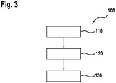
- FIG. 10 shows a schematic representation of a flowchart on the basis of a method 100 for operating an electrical machine 2.
- a step 110 the connections of the electrical machine 2 are first activated with an alternating voltage. This control of the electrical machine 2 takes place in order to set a predetermined torque or a predetermined speed, as is carried out in normal operation. If a malfunction occurs during this control mode, it may be necessary to end the control mode and switch to free-running mode. If an event is detected that requires the change from control mode to freewheeling mode, control mode is terminated and, in step 120, the amplitude of the alternating voltage with which the electrical machine is controlled is set to a predetermined value. This predetermined value is preferably the freewheeling voltage of the electrical machine at the current speed. This speed-dependent freewheeling voltage of the electrical machine can be calculated beforehand in a further step or, alternatively, can also be read from a memory.
- the changeover to freewheeling then takes place.
- the electrical machine is no longer actively controlled. Rather, the connections of the electrical machine 2 are electrically isolated from one another in this freewheel.
- the switching elements of an inverter that controls the electrical machine 2 in regular operation are all open in this switching state.
- the present invention relates to changing an electrical machine from normal operation to freewheeling.
- a further control phase is introduced between the end of normal operation and freewheeling, during which the voltage at the connections of the electric machine from the previous
- the voltage set in normal operation is continuously adapted to the expected free-wheeling voltage of the electrical machine.
Landscapes
- Engineering & Computer Science (AREA)
- Power Engineering (AREA)
- Transportation (AREA)
- Mechanical Engineering (AREA)
- Life Sciences & Earth Sciences (AREA)
- Sustainable Development (AREA)
- Sustainable Energy (AREA)
- Control Of Ac Motors In General (AREA)
- Control Of Motors That Do Not Use Commutators (AREA)
Description
Die vorliegende Erfindung betrifft eine Vorrichtung und ein Verfahren zum Betreiben einer elektrischen Maschine. Insbesondere betrifft die vorliegende Erfindung eine Vorrichtung und ein Verfahren zum Betreiben einer elektrischen Maschine für den Wechsel von einem Regelbetrieb zu einem Freilaufbetrieb.The present invention relates to a device and a method for operating an electrical machine. In particular, the present invention relates to a device and a method for operating an electrical machine for changing from a control mode to a freewheeling mode.
Elektrische Maschinen, wie beispielsweise permanent erregte Synchronmaschinen, finden in zahlreichen technischen Bereichen Einsatz. Beispielsweise werden solche permanent erregten Synchronmaschinen in Kraftfahrzeugen eingesetzt. Aus Sicherheitsgründen müssen dabei Vorkehrungen für einen Betriebszustand bei einem Fehlerfall getroffen werden. Eine Möglichkeit einen solchen Betriebszustand einzustellen ist dabei der sogenannte Freilauf. Dabei werden alle Anschlüsse der elektrischen Maschine voneinander getrennt und es erfolgt keine aktive Ansteuerung der elektrischen Maschine mit einer Spannung. Ein weiterer sicherer Betriebszustand ist der sogenannte aktive Kurzschluss. Dabei werden mittels geeigneter Schaltelemente die Anschlüsse der elektrischen Maschine kurzgeschlossen.Electrical machines, such as permanently excited synchronous machines, are used in numerous technical areas. For example, such permanently excited synchronous machines are used in motor vehicles. For safety reasons, precautions must be taken for an operating state in the event of a fault. One possibility to set such an operating state is the so-called freewheel. All connections of the electrical machine are separated from one another and there is no active control of the electrical machine with a voltage. Another safe operating state is the so-called active short circuit. The connections of the electrical machine are short-circuited by means of suitable switching elements.
Die Deutsche Patentanmeldung
Es besteht daher ein Bedarf nach einer Vorrichtung und einem Verfahren zum Betreiben einer elektrischen Maschine, das einen verbesserten Wechsel vom Regelbetrieb in den Freilauf ermöglicht.There is therefore a need for a device and a method for operating an electrical machine that enables an improved change from normal operation to freewheeling.
Die vorliegende Erfindung schafft hierzu eine Vorrichtung und eine Verfahren zum Betreiben einer elektrischen Maschine mit den Merkmalen der unabhängigen Patentansprüche.To this end, the present invention creates a device and a method for operating an electrical machine having the features of the independent claims.
Der vorliegenden Erfindung liegt die Idee zugrunde, bei der Anforderung eines Wechsels vom Regelbetrieb zum Freilaufbetrieb einer elektrischen Maschine diesen Wechsel nicht schlagartig auszuführen, sondern zunächst die Spannung an den Anschlüssen der elektrischen Maschine geregelt auf die zu erwartenden Spannungswerte während des Freilaufbetriebs anzupassen. Erst nachdem an den Anschlüssen der elektrischen Maschine die Spannungsverhältnisse eingestellt worden sind, die den Spannungsverhältnissen des Freilaufbetriebs entsprechen, wird daraufhin tatsächlich in den Freilaufbetrieb gewechselt. Auf diese Weise können Spannungssprünge vermieden, oder zumindest reduziert werden. Beim Umschalten vom Regelbetrieb in den Freilaufbetrieb entstehen somit keine für das Gesamtsystem schädlichen Spannungssprünge, die zu Überspannungen und damit zu Beschädigungen des Systems führen können. Insbesondere können durch das sanfte Wechseln vom Regelbetrieb in den Freilaufbetrieb und der sich daran anschließenden Freilaufphase unkontrollierbare Spannungserhöhungen in einem Zwischenkreis verhindert werden. Dies führt auch zu einer geringeren Belastung der Energieversorgung, wie zum Beispiel der Traktionsbatterie eines Elektro- oder Hybridfahrzeugs. Somit können diese relativ teuren und sensiblen Batterien geschont werden und damit wird die Lebensdauer der Batterien erhöht.The present invention is based on the idea of not performing this change suddenly when a change from normal operation to freewheeling operation of an electrical machine is requested, but first adjusting the voltage at the connections of the electrical machine in a controlled manner to the expected voltage values during freewheeling operation. Only after the voltage ratios have been set at the connections of the electrical machine that correspond to the voltage ratios of the freewheeling mode is there actually a change to the freewheeling mode. In this way, voltage jumps can be avoided or at least reduced. When switching from normal operation to freewheeling operation, there are no voltage jumps that are harmful to the overall system and that could lead to overvoltages and thus damage to the system. In particular, the gentle change from regular operation to the freewheeling operation and the subsequent freewheeling phase, uncontrollable voltage increases in an intermediate circuit are prevented. This also leads to a lower load on the energy supply, such as the traction battery of an electric or hybrid vehicle. In this way, these relatively expensive and sensitive batteries can be spared and the service life of the batteries is increased.
Wird an der elektrischen Maschine die Freilaufspannung zunächst aktiv durch Regeln des Wechselrichters eingestellt, so kann daraufhin in den Freilaufbetrieb gewechselt werden, ohne dass es zu Spannungssprüngen kommt.. Die Freilaufspannung der elektrischen Maschine ist in der Regel eine von der Drehzahl abhängige Funktion. Durch Anpassen der einzustellenden Spannung beim Übergang vom Regelbetrieb in den Freilaufbetrieb in Abhängigkeit von der Drehzahl kann somit eine sehr gute Anpassung der einzustellenden Spannung erreicht werden.If the freewheeling voltage is initially actively set on the electrical machine by regulating the inverter, then it is possible to switch to freewheeling mode without voltage jumps occurring. The freewheeling voltage of the electrical machine is usually a function that depends on the speed. By adapting the voltage to be set during the transition from control mode to freewheeling operation as a function of the speed, a very good adaptation of the voltage to be set can be achieved.
Gemäß einem Ausführungsbeispiel umfasst die Vorrichtung einen Drehzahlsensor, der dazu ausgelegt ist, die Drehzahl der elektrischen Maschine zu bestimmen. Durch die Bestimmung der Drehzahl der elektrischen Maschine mittels eines Drehzahlsensors kann eine sehr genaue Bestimmung der Drehzahl und somit eine präzise Anpassung der einzustellenden Freilaufspannung erreicht werden. Alternativ ist es auch möglich, die Drehzahl aus anderen Quellen zu beziehen, beispielsweise die zuvor im Regelbetrieb eingestellte Solldrehzahl zu verwenden, oder die Drehzahl basierend auf einem Modell abzuschätzen.According to one exemplary embodiment, the device comprises a speed sensor which is designed to determine the speed of the electrical machine. By determining the speed of the electrical machine by means of a speed sensor, a very precise determination of the speed and thus a precise adjustment of the freewheeling voltage to be set can be achieved. Alternatively, it is also possible to obtain the speed from other sources, for example to use the setpoint speed previously set in control mode, or to estimate the speed based on a model.
Gemäß einem Ausführungsbeispiel umfasst der Wechselrichter eine Mehrzahl von Halbleiterschaltern, wobei im Freilaufbetrieb die Halbleiterschalter geöffnet sind. Halbleiterschalter eignen sich besonders gut zur Ansteuerung elektrischer Maschinen. Diese Halbleiterschalter schalten verschleißfrei und sehr schnell. Darüber hinaus sind sie heutzutage sehr kostengünstig erhältlich.According to one exemplary embodiment, the inverter comprises a plurality of semiconductor switches, the semiconductor switches being open in free-wheeling operation. Semiconductor switches are particularly suitable for controlling electrical machines. These semiconductor switches switch wear-free and very quickly. In addition, they are available very cheaply these days.
Ein weiteres Ausführungsbeispiel umfasst eine elektrische Antriebsvorrichtung mit einer elektrische Maschine und einer erfindungsgemäßen Vorrichtung zum Betreiben der elektrischen Maschine.Another exemplary embodiment comprises an electric drive device with an electric machine and a device according to the invention for operating the electric machine.
Gemäß einem weiteren Ausführungsbeispiel umfasst die elektrische Maschine eine permanent erregte Synchronmaschine.According to a further exemplary embodiment, the electrical machine comprises a permanently excited synchronous machine.
Gemäß einem weiteren Ausführungsbeispiel schafft die vorliegende Erfindung ein Kraftfahrzeug mit einer erfindungsgemäßen elektrischen Antriebsvorrichtung.According to a further exemplary embodiment, the present invention creates a motor vehicle with an electric drive device according to the invention.
Weitere Vorteile und Ausführungsbeispiele ergeben sich aus der nachfolgenden Beschreibung unter Bezug auf die beigefügten Figuren.Further advantages and exemplary embodiments emerge from the following description with reference to the accompanying figures.
Dabei zeigen:
- Figur 1:
- eine schematische Darstellung für die Ansteuerung einer elektrischen Maschine im Freilauf;
- Figur 2:
- eine schematische Darstellung eines elektrischen Antriebssystems gemäß einem Ausführungsbeispiel der vorliegenden Erfindung; und
- Figur 3:
- eine schematische Darstellung eines Ablaufdiagramms für ein Verfahren, wie es einem weiteren Ausführungsbeispiel zugrunde liegt.
- Figure 1:
- a schematic representation for the control of an electrical machine in freewheeling;
- Figure 2:
- a schematic representation of an electric drive system according to an embodiment of the present invention; and
- Figure 3:
- a schematic representation of a flow chart for a method as it is based on a further embodiment.
Der Wechselrichter 1 wird von einer Gleichspannungsquelle (hier nicht dargestellt) gespeist. Dabei kann es sich bei der Gleichspannungsquelle beispielsweise um eine Batterie, wie zum Beispiel die Traktionsbatterie eines Hybrid- oder Elektrofahrzeuges handeln. Weitere Gleichspannungsquellen oder auch ein AC-DC-Konverter zur Speisung des Wechselrichters sind darüber hinaus ebenso möglich. Der Wechselrichter 1 weist dabei eine Mehrzahl von Schaltelementen 10a-10f auf. Bei diesen Schaltelementen kann es sich vorzugsweise um Halbleiterschaltelemente, wie zum Beispiel IGBT oder MOSFET handeln. Solche Halbleiterschaltelemente sind in der Lage verschleißfrei eine große Anzahl von Schaltzyklen bei sehr schneller Schaltfrequenz auszuführen. Vorzugsweise ist zu jedem dieser Schaltelemente 10a-10f darüber hinaus parallel eine Freilaufdiode angeordnet.The inverter 1 is fed by a DC voltage source (not shown here). The DC voltage source can be, for example, a battery, such as the traction battery of a hybrid or electric vehicle. Further DC voltage sources or an AC-DC converter for feeding the inverter are also possible. The inverter 1 has a plurality of switching
Im Freilaufbetrieb sind dabei alle Schaltelemente 10a-10f des Wechselrichters geöffnet. Die Anschlüsse der elektrischen Maschine 2 sind somit alle voneinander elektrisch getrennt. Lediglich durch die den Halbleiterschaltelementen parallel geschalteten Freilaufdioden ist in diesem Freilaufbetrieb ein Stromfluss möglich.In freewheeling operation, all switching
Im Regelbetrieb dagegen werden die Schaltelemente 10a-10f gezielt angesteuert, um dabei durch geeignete Modulation an den Anschlüssen der elektrischen Maschine 2 jeweils ein Spannungssignal bereitzustellen. Je nach Modulation bzw. Amplitude der so an den Anschlüssen der elektrischen Maschine 2 bereitgestellten Spannung kann somit in dem Regelbetrieb ein gewünschtes Drehmoment bzw. eine gewünschte Drehzahl eingestellt werden.
Kommt es bei der elektrischen Antriebsvorrichtung zu einer Störung, so kann es dabei erforderlich werden, dass die elektrische Maschine 2 nicht länger im Regelbetrieb betrieben werden darf, sondern in den Freilaufbetrieb wechseln muss. Bei einem abrupten Wechsel vom Regelbetrieb in den Freilaufbetrieb, bei dem plötzlich unmittelbar alle Schaltelemente 10a-10f geöffnet werden, kann es dabei zu unerwünschten Spannungsüberhöhungen kommen. Diese Spannungsüberhöhungen müssen bei der Dimensionierung des Wechselrichters 1 und der elektrischen Maschine 2 berücksichtigt werden. Darüber hinaus besteht die Gefahr, dass solche Spannungsüberhöhungen die Komponenten in der elektrischen Antriebsvorrichtung beschädigen oder zumindest die Lebensdauer negativ beeinflussen.In normal operation, on the other hand, the
If there is a malfunction in the electric drive device, it may be necessary that the
Hierzu wird durch den Regler 11 zunächst die Drehzahl der elektrischen Maschine 2 bestimmt. Beispielsweise kann die elektrische Maschine 2 hierzu über einen Drehzahlgeber 20 verfügen, der die aktuelle Drehzahl der elektrischen Maschine 2 erfasst und dem Regler 11 bereitstellt. Darüber hinaus ist es auch möglich, einen Sollwert für die aktuelle Drehzahl zum Zeitpunkt der Anforderung für den Wechsel vom Regelbetrieb in den Freilaufbetrieb als Ausgangsgröße für die Bestimmung der Freilaufspannung zu verwenden. Alternative Verfahren zur Bestimmung der Drehzahl, beispielsweise ein Modellierung des gesamten Antriebssystems und eine darauf basierende Berechnung der Drehzahl der elektrischen Maschine 2 ist ebenso möglich.For this purpose, the
Daraufhin ermittelt der Regler 11 basierend auf der Drehzahl der elektrischen Maschine 2 die zu dieser Drehzahl korrespondierende Freilaufspannung der elektrischen Maschine 2. Diese Freilaufspannung wird in der Regel geringer sein, als die zum Zeitpunkt der Anforderung eingestellte Spannung während des Regelbetriebs.The
Der Regler 11 wird daraufhin sukzessive die durch den Wechselrichter 1 an den Anschlüssen der elektrischen Maschine 2 bereitgestellte Spannung von der aktuellen Spannung auf den ermittelten Wert der Freilaufspannung anpassen. Diese Anpassung kann beispielsweise innerhalb einer vorbestimmten Zeitdauer Δt erfolgen. Beispielsweise haben sich für die Anpassung der Spannungsverhältnisse von der Regelspannung zu der Freilaufspannung Zeitintervalle von einigen Millisekunden, beispielsweise 5 Millisekunden bis 20 Millisekunden als geeignet erwiesen. Andere Zeitintervalle sind jedoch ebenso möglich.The
Alternativ ist es auch möglich, durch den Regler 11 die Spannung an den Anschlüssen der elektrischen Maschine 2 mit einer vorgegebenen Spannungssteilheit zu variieren. Beispielsweise kann dabei die Amplitude der an den Anschlüssen der elektrischen Maschine 2 einzustellenden Wechselspannung mit einer vorgegebenen Spannungsdifferenz pro Zeiteinheit abgesenkt (oder gegebenenfalls auch erhöht) werden. Somit kann gewährleistet werden, dass es zu keiner übermäßigen Spannungsveränderungen während des Anpassungsvorgangs kommt.Alternatively, it is also possible to use the
Der Regler 11 kann dabei mögliche vorhandene Sensorwerte, wie Drehzahl oder gegebenenfalls auch Spannungs- bzw. Stromverhältnisse etc. mit in den Regelvorgang einbeziehen, um die einzustellende Spannung an der elektrischen Maschine 2 möglichst präzise auf die aktuelle Freilaufspannung einzustellen.The
Die einzustellende Freilaufspannung als Funktion der Drehzahl kann dabei beispielsweise in einem Speicher innerhalb oder außerhalb des Reglers 11 abgelegt werden. Beispielsweise können hierzu zur Vorgabe der einzustellenden Freilaufspannungen in Abhängigkeit von der Drehzahl die erforderlichen Spannungswerte in einer Tabelle bereitgestellt werden. Um dabei die Anzahl der erforderlichen Spannungswerte, die hierzu abgespeichert werden müssen, minimal zu halten, kann für Drehzahlen zwischen zwei abgespeicherten Stützstellen darüber hinaus die Freilaufspannung auch interpoliert werden. Alternative Möglichkeiten zur Bestimmung der drehzahlabhängigen Freilaufspannungen sind darüber hinaus ebenso möglich. Beispielsweise kann die Freilaufspannung auch als ein Modell innerhalb des Reglers 11 abgelegt werden, so dass die Freilaufspannung als mathematische Funktion in Abhängigkeit von der Drehzahl ermittelt werden kann. Aber auch eine externe Vorgabe von Freilaufspannungen durch eine weitere Schnittstelle am Regler 11 ist ebenso möglich.The freewheeling voltage to be set as a function of the speed can be stored in a memory inside or outside the
Der Regler 11 kann dabei die einzustellende Freilaufspannung auch als Stellgrößen für die d- bzw. q-Komponenten der Stellgrößen bereitgestellt werden. der Zusammenhang zwischen d- und q-Komponenten und den Phasenspannungen an den Anschlüssen der elektrischen Maschine 2 ist dabei bereits bekannt. Zur Einstellung der erforderlichen Freilaufspannung wird dabei die d-Komponente der Spannung auf Null geregelt. Bei einer vorgegebenen Übergangszeit Δt ergibt sich dabei für die d-Komponente der Spannung Ud(t): ![]()
![]()
Dabei ist Ud,init die Regelspannung zu Beginn des Übergangs für die d-Komponente.U d, init is the control voltage at the beginning of the transition for the d component.
Die q-Komponente der Stellgröße wird dabei wie folgt eingeregelt: ![]()
![]()
Dabei ist Uq,init die Stellgröße der q-Komponente der Spannung zu Beginn des Übergangs vom Regel- in den Freilaufbetrieb und Uq(n) die Leerlaufspannung der elektrischen Maschine in Abhängigkeit von der Drehzahl n.U q, init is the manipulated variable of the q component of the voltage at the beginning of the transition from control to free-running mode and U q (n) is the no-load voltage of the electrical machine as a function of speed n.
Somit wird die d-Spannungskomponente am Ende des Regelvorgangs zu Null geregelt, während die q-Spannungskomponente auf die Leerlaufspannung der elektrischen Maschine für die jeweilige Drehzahl eingestellt wird.Thus, the d-voltage component is regulated to zero at the end of the control process, while the q-voltage component is set to the open-circuit voltage of the electrical machine for the respective speed.
Diese Ausregelung der Spannungskomponenten kann somit unabhängig von den aktuellen Phasenstromwerten erfolgen. Daher ist bei einer solchen Anpassung der Spannungswerte an den Anschlüssen der elektrischen Maschine 2 kein Stromsensor zur Ermittlung der Phasenströme erforderlich. Die erfindungsgemäße Anpassung der Spannungen an den Anschlüssen der elektrischen Maschine kann daher auch dann erfolgen, wenn der Freilaufbetrieb beispielsweise aufgrund eines Fehlers in den Sensoren für die Phasenströme auftreten würde.This adjustment of the voltage components can thus take place independently of the current phase current values. Therefore, with such an adaptation of the voltage values at the connections of the
Nachdem an den Anschlüssen der elektrischen Maschine 2 eine Spannung eingestellt worden ist, die dem vorbestimmten Wert, also vorzugsweise der Freilaufspannung, entspricht, erfolgt daraufhin der Wechsel in den Freilauf. Bei diesem Freilauf wird die elektrische Maschine nicht länger aktiv angesteuert. Vielmehr werden in diesem Freilauf die Anschlüsse der elektrischen Maschine 2 voneinander elektrisch getrennt. Die Schaltelemente eines Wechselrichters, der die elektrische Maschine 2 im Regelbetrieb ansteuert, sind dabei in diesem Schaltzustand alle geöffnet.After a voltage has been set at the connections of the
Zusammenfassend betrifft die vorliegende Erfindung den Wechsel einer elektrischen Maschine vom Regelbetrieb in den Freilauf. Zur Vermeidung von Spannungsüberhöhungen und damit verbundenen Beeinträchtigungen der elektrischen Maschine und der weiteren Komponenten, insbesondere von Batterien, wird zwischen dem Ende des Regelbetriebs und dem Freilauf eine weitere Regelphase eingeführt, während der die Spannung an den Anschlüssen der elektrischen Maschine von der zuvor im Regelbetrieb eingestellten Spannung kontinuierlich auf die zu erwartende Freilaufspannung der elektrischen Maschine angepasst wird.In summary, the present invention relates to changing an electrical machine from normal operation to freewheeling. To avoid excessive voltage and the associated impairment of the electrical machine and the other components, especially batteries, a further control phase is introduced between the end of normal operation and freewheeling, during which the voltage at the connections of the electric machine from the previous The voltage set in normal operation is continuously adapted to the expected free-wheeling voltage of the electrical machine.
Claims (7)
- Device for operating an electric machine (2) for the transition from a regulated operating mode to a freewheeling mode,
including an inverter (1),
wherein the inverter comprises a plurality of switching elements (10a-10f),
wherein the inverter provides an AC voltage at the terminals of the electric machine (2) by actuating the switching elements (10a-10f) in a regulated operating mode,
wherein the inverter electrically disconnects the terminals of the electric machine (2) from each other by opening the switching elements (10a-10f) in a freewheeling mode,
wherein the inverter is designed to provide an AC voltage at the terminals of the electric machine (2) in the regulated operating mode, and to electrically disconnect the terminals of the electric machine (2) from each other in the freewheeling mode,
characterized in that
the inverter (1) is designed to set the amplitude of the AC voltage provided at the terminals of the electric machine (2) to a predetermined value within a predetermined period of time during a transition from the regulated operating mode to the freewheeling mode. - Device according to Claim 1, including a controller (11), which is designed to determine a rotational speed of the electric machine (2) and to ascertain a voltage that corresponds to the voltage at the terminals of the electric machine (2) in the freewheeling mode, wherein the inverter (11) initially sets the amplitude of the voltage at the terminals of the electric machine (2) to the ascertained voltage during a transition from the regulated operating mode to the freewheeling mode.
- Device according to Claim 2, including a rotational speed sensor (20), which is designed to determine the rotational speed of the electric machine (2).
- Electric drive device, including:an electric machine (2); anda device according to one of Claims 1 to 3.
- Motor vehicle including an electric drive device according to Claim 4.
- Method (100) for operating an electric machine (2) for the transition from a regulated operating mode to a freewheeling mode, including the steps of:driving (110) the terminals of the electric machine (2) with an AC voltage in a regulated operating mode;detecting a signalling for a transition from the regulated operating mode to a freewheeling mode;setting (120) the amplitude of the AC voltage with which the electric machine (2) is driven to a predetermined value within a predetermined period of time; andwherein the transition to the freewheeling state takes place after the amplitude of the AC voltage at the terminals of the electric machine (2) has been set, wherein the terminals of the electric machine (2) are electrically disconnected (130) from each another in the freewheeling state.
- Method (100) according to Claim 6, wherein the step (120) for setting the AC voltage drives the electric machine (2) with an AC voltage that corresponds to a terminal voltage of the electric machine in the freewheeling state.
Applications Claiming Priority (2)
| Application Number | Priority Date | Filing Date | Title |
|---|---|---|---|
| DE102013226577.8A DE102013226577A1 (en) | 2013-12-19 | 2013-12-19 | Apparatus and method for operating an electrical machine |
| PCT/EP2014/074594 WO2015090756A1 (en) | 2013-12-19 | 2014-11-14 | Device and method for operating an electric machine |
Publications (2)
| Publication Number | Publication Date |
|---|---|
| EP3083319A1 EP3083319A1 (en) | 2016-10-26 |
| EP3083319B1 true EP3083319B1 (en) | 2021-06-09 |
Family
ID=51905047
Family Applications (1)
| Application Number | Title | Priority Date | Filing Date |
|---|---|---|---|
| EP14799738.1A Active EP3083319B1 (en) | 2013-12-19 | 2014-11-14 | Apparatus and method for operating an electric machine |
Country Status (5)
| Country | Link |
|---|---|
| US (1) | US9825571B2 (en) |
| EP (1) | EP3083319B1 (en) |
| CN (1) | CN105813880B (en) |
| DE (1) | DE102013226577A1 (en) |
| WO (1) | WO2015090756A1 (en) |
Families Citing this family (1)
| Publication number | Priority date | Publication date | Assignee | Title |
|---|---|---|---|---|
| FR3115944A1 (en) * | 2020-11-03 | 2022-05-06 | Nidec Psa Emotors | Method for controlling an inverter and corresponding system |
Family Cites Families (16)
| Publication number | Priority date | Publication date | Assignee | Title |
|---|---|---|---|---|
| JPH0984208A (en) * | 1995-09-14 | 1997-03-28 | Denso Corp | Electric car controller |
| US5874818A (en) * | 1997-06-11 | 1999-02-23 | Agile Systems, Inc. | Method and apparatus for sensing load current in a motor controller |
| DE10146527A1 (en) * | 2001-09-21 | 2003-04-24 | Siemens Ag | Converter with a line and load side self-commutated pulse converter |
| JP3672876B2 (en) * | 2002-02-26 | 2005-07-20 | 株式会社東芝 | Vector control inverter device and rotary drive device |
| GB2413905B (en) * | 2004-05-05 | 2006-05-03 | Imra Europ S A S Uk Res Ct | Permanent magnet synchronous motor and controller therefor |
| DE102006003254A1 (en) * | 2006-01-24 | 2007-07-26 | Robert Bosch Gmbh | Operating method for electrical machine with pulse-controlled inverter in case of disturbance, involves switching electrical machine into de-energizing mode and into short-circuit mode |
| JP4085112B2 (en) * | 2006-01-31 | 2008-05-14 | ファナック株式会社 | Motor control method and motor control apparatus |
| DE102006018053A1 (en) * | 2006-04-19 | 2007-10-31 | Daimlerchrysler Ag | Drive system for an electric machine |
| US7279862B1 (en) * | 2006-08-04 | 2007-10-09 | Gm Global Technology Operations, Inc. | Fault handling of inverter driven PM motor drives |
| US7489097B2 (en) * | 2006-11-02 | 2009-02-10 | Chrysler Llc | Sensorless position detection for a brushless direct current motor during inverter standby |
| DE102007020509A1 (en) | 2007-05-02 | 2008-11-06 | Robert Bosch Gmbh | Error treatment in an electric machine of a hybrid drive |
| US8319460B2 (en) * | 2009-10-27 | 2012-11-27 | GM Global Technology Operations LLC | Method and system for initiating operation of an electric motor |
| DE102009047616A1 (en) | 2009-12-08 | 2011-06-09 | Robert Bosch Gmbh | Inverter arrangement for operating an electric motor |
| DE102012002023A1 (en) * | 2011-06-21 | 2012-12-27 | Volkswagen Aktiengesellschaft | Method for operating inverter circuit of permanent magnet synchronous electric machine e.g. electric motor, involves operating electric machine in active short-circuit mode, when rotational speed is above threshold value |
| DE102011079566B4 (en) * | 2011-07-21 | 2024-09-05 | Robert Bosch Gmbh | Method for operating an electrical network and device for controlling an electrical network |
| DE102012101508A1 (en) | 2012-02-24 | 2013-08-29 | Volkswagen Aktiengesellschaft | Method for operating e.g. permanently excited synchronous machine for motor car, involves comparing voltage in intermediate circuit with minimum limit voltage value in circuit, to open converter valves so as to drive machine |
-
2013
- 2013-12-19 DE DE102013226577.8A patent/DE102013226577A1/en active Pending
-
2014
- 2014-11-14 WO PCT/EP2014/074594 patent/WO2015090756A1/en not_active Ceased
- 2014-11-14 CN CN201480069836.5A patent/CN105813880B/en active Active
- 2014-11-14 EP EP14799738.1A patent/EP3083319B1/en active Active
- 2014-11-14 US US15/104,590 patent/US9825571B2/en active Active
Non-Patent Citations (1)
| Title |
|---|
| None * |
Also Published As
| Publication number | Publication date |
|---|---|
| US9825571B2 (en) | 2017-11-21 |
| US20160380569A1 (en) | 2016-12-29 |
| DE102013226577A1 (en) | 2015-06-25 |
| EP3083319A1 (en) | 2016-10-26 |
| CN105813880B (en) | 2018-01-26 |
| WO2015090756A1 (en) | 2015-06-25 |
| CN105813880A (en) | 2016-07-27 |
Similar Documents
| Publication | Publication Date | Title |
|---|---|---|
| EP3083320B1 (en) | Apparatus and method for operating an electric machine | |
| EP3083321B1 (en) | Apparatus and method for operating an electric machine | |
| DE10050383B4 (en) | Hybrid vehicle and method for generating a driving force of a hybrid vehicle | |
| DE102015218732A1 (en) | An electric motor drive control apparatus, an electric power steering apparatus, an electrically operated brake apparatus and an electrically operated pump apparatus | |
| DE112007001580T5 (en) | Inverter control device and method for its operation | |
| WO2008138864A1 (en) | Method and device for operating a control unit for controlling an electrical machine | |
| EP3058652B1 (en) | Control unit with safety shutdown | |
| WO2005048446A1 (en) | Braking method for a synchronous machine | |
| DE102017108396A1 (en) | ERROR SHUTTER CONTROL OF AN ELECTRICAL MACHINE IN A VEHICLE OR OTHER DC TORQUE SYSTEMS | |
| EP3145750A1 (en) | Method for switching an inverter of an electric drive of a motor vehicle and a correspondingly switchable inverter | |
| EP3545617B1 (en) | Protective device for an electric drive system, electric drive system, and method for operating an electric drive system | |
| DE102011075789A1 (en) | Method for operating induction machine e.g. permanent magnet synchronous machine of pulse inverter for motor car, involves adjusting voltage vector and setting pulse width modulation command value constant for defective power switch | |
| DE112021006811T5 (en) | ENGINE DRIVE DEVICE WITH CHARGING CONTROL UNIT | |
| EP4256691B1 (en) | Method for operating an electric machine, device for operating an electric machine, and electric drive system | |
| EP3083319B1 (en) | Apparatus and method for operating an electric machine | |
| DE102018203515A1 (en) | Control system, control device and control method for a wound induction machine | |
| EP2570290A1 (en) | Drive system of a battery-operated vehicle with a frequency converter fed permanently excited synchronous machine | |
| EP2654155B1 (en) | Power converter, and method for operating a power converter | |
| EP3172831A1 (en) | Method for operating an at least generator-operable electric machine and means for the implementation thereof | |
| DE102015104466A1 (en) | ELECTRIC VEHICLE AND METHOD | |
| DE102009049623A1 (en) | Method for regulating direct current voltage of intermediate circuit of electrically driven motor vehicle, involves controlling inverter based on zero crossing of generator current, induced voltage and charge quantity | |
| DE102014222939B4 (en) | Vehicle electric power conversion device | |
| EP2560277B1 (en) | Protection of an alternating current engine in the field weakening range | |
| DE102017217865A1 (en) | Monitoring the measurement components required for current measurement on an electrical coil | |
| DE102024106471A1 (en) | Wiper control device |
Legal Events
| Date | Code | Title | Description |
|---|---|---|---|
| PUAI | Public reference made under article 153(3) epc to a published international application that has entered the european phase |
Free format text: ORIGINAL CODE: 0009012 |
|
| 17P | Request for examination filed |
Effective date: 20160719 |
|
| AK | Designated contracting states |
Kind code of ref document: A1 Designated state(s): AL AT BE BG CH CY CZ DE DK EE ES FI FR GB GR HR HU IE IS IT LI LT LU LV MC MK MT NL NO PL PT RO RS SE SI SK SM TR |
|
| AX | Request for extension of the european patent |
Extension state: BA ME |
|
| DAX | Request for extension of the european patent (deleted) | ||
| STAA | Information on the status of an ep patent application or granted ep patent |
Free format text: STATUS: EXAMINATION IS IN PROGRESS |
|
| 17Q | First examination report despatched |
Effective date: 20200120 |
|
| RAP1 | Party data changed (applicant data changed or rights of an application transferred) |
Owner name: ROBERT BOSCH GMBH |
|
| REG | Reference to a national code |
Ref country code: DE Ref legal event code: R079 Ref document number: 502014015663 Country of ref document: DE Free format text: PREVIOUS MAIN CLASS: B60L0003000000 Ipc: H02P0025024000 |
|
| RIC1 | Information provided on ipc code assigned before grant |
Ipc: H02P 25/024 20160101AFI20200917BHEP Ipc: H02P 27/08 20060101ALI20200917BHEP Ipc: H02P 29/024 20160101ALI20200917BHEP Ipc: H02P 3/18 20060101ALI20200917BHEP Ipc: H02P 23/14 20060101ALI20200917BHEP |
|
| GRAP | Despatch of communication of intention to grant a patent |
Free format text: ORIGINAL CODE: EPIDOSNIGR1 |
|
| GRAJ | Information related to disapproval of communication of intention to grant by the applicant or resumption of examination proceedings by the epo deleted |
Free format text: ORIGINAL CODE: EPIDOSDIGR1 |
|
| GRAP | Despatch of communication of intention to grant a patent |
Free format text: ORIGINAL CODE: EPIDOSNIGR1 |
|
| STAA | Information on the status of an ep patent application or granted ep patent |
Free format text: STATUS: GRANT OF PATENT IS INTENDED |
|
| INTG | Intention to grant announced |
Effective date: 20201204 |
|
| GRAJ | Information related to disapproval of communication of intention to grant by the applicant or resumption of examination proceedings by the epo deleted |
Free format text: ORIGINAL CODE: EPIDOSDIGR1 |
|
| STAA | Information on the status of an ep patent application or granted ep patent |
Free format text: STATUS: EXAMINATION IS IN PROGRESS |
|
| GRAP | Despatch of communication of intention to grant a patent |
Free format text: ORIGINAL CODE: EPIDOSNIGR1 |
|
| STAA | Information on the status of an ep patent application or granted ep patent |
Free format text: STATUS: GRANT OF PATENT IS INTENDED |
|
| INTC | Intention to grant announced (deleted) | ||
| INTG | Intention to grant announced |
Effective date: 20210225 |
|
| GRAS | Grant fee paid |
Free format text: ORIGINAL CODE: EPIDOSNIGR3 |
|
| GRAA | (expected) grant |
Free format text: ORIGINAL CODE: 0009210 |
|
| STAA | Information on the status of an ep patent application or granted ep patent |
Free format text: STATUS: THE PATENT HAS BEEN GRANTED |
|
| AK | Designated contracting states |
Kind code of ref document: B1 Designated state(s): AL AT BE BG CH CY CZ DE DK EE ES FI FR GB GR HR HU IE IS IT LI LT LU LV MC MK MT NL NO PL PT RO RS SE SI SK SM TR |
|
| REG | Reference to a national code |
Ref country code: GB Ref legal event code: FG4D Free format text: NOT ENGLISH |
|
| REG | Reference to a national code |
Ref country code: CH Ref legal event code: EP Ref country code: AT Ref legal event code: REF Ref document number: 1401314 Country of ref document: AT Kind code of ref document: T Effective date: 20210615 |
|
| REG | Reference to a national code |
Ref country code: DE Ref legal event code: R096 Ref document number: 502014015663 Country of ref document: DE |
|
| REG | Reference to a national code |
Ref country code: IE Ref legal event code: FG4D Free format text: LANGUAGE OF EP DOCUMENT: GERMAN |
|
| REG | Reference to a national code |
Ref country code: LT Ref legal event code: MG9D |
|
| PG25 | Lapsed in a contracting state [announced via postgrant information from national office to epo] |
Ref country code: HR Free format text: LAPSE BECAUSE OF FAILURE TO SUBMIT A TRANSLATION OF THE DESCRIPTION OR TO PAY THE FEE WITHIN THE PRESCRIBED TIME-LIMIT Effective date: 20210609 Ref country code: BG Free format text: LAPSE BECAUSE OF FAILURE TO SUBMIT A TRANSLATION OF THE DESCRIPTION OR TO PAY THE FEE WITHIN THE PRESCRIBED TIME-LIMIT Effective date: 20210909 Ref country code: LT Free format text: LAPSE BECAUSE OF FAILURE TO SUBMIT A TRANSLATION OF THE DESCRIPTION OR TO PAY THE FEE WITHIN THE PRESCRIBED TIME-LIMIT Effective date: 20210609 Ref country code: FI Free format text: LAPSE BECAUSE OF FAILURE TO SUBMIT A TRANSLATION OF THE DESCRIPTION OR TO PAY THE FEE WITHIN THE PRESCRIBED TIME-LIMIT Effective date: 20210609 |
|
| REG | Reference to a national code |
Ref country code: NL Ref legal event code: MP Effective date: 20210609 |
|
| PG25 | Lapsed in a contracting state [announced via postgrant information from national office to epo] |
Ref country code: GR Free format text: LAPSE BECAUSE OF FAILURE TO SUBMIT A TRANSLATION OF THE DESCRIPTION OR TO PAY THE FEE WITHIN THE PRESCRIBED TIME-LIMIT Effective date: 20210910 Ref country code: LV Free format text: LAPSE BECAUSE OF FAILURE TO SUBMIT A TRANSLATION OF THE DESCRIPTION OR TO PAY THE FEE WITHIN THE PRESCRIBED TIME-LIMIT Effective date: 20210609 Ref country code: RS Free format text: LAPSE BECAUSE OF FAILURE TO SUBMIT A TRANSLATION OF THE DESCRIPTION OR TO PAY THE FEE WITHIN THE PRESCRIBED TIME-LIMIT Effective date: 20210609 Ref country code: SE Free format text: LAPSE BECAUSE OF FAILURE TO SUBMIT A TRANSLATION OF THE DESCRIPTION OR TO PAY THE FEE WITHIN THE PRESCRIBED TIME-LIMIT Effective date: 20210609 Ref country code: NO Free format text: LAPSE BECAUSE OF FAILURE TO SUBMIT A TRANSLATION OF THE DESCRIPTION OR TO PAY THE FEE WITHIN THE PRESCRIBED TIME-LIMIT Effective date: 20210909 |
|
| PG25 | Lapsed in a contracting state [announced via postgrant information from national office to epo] |
Ref country code: SM Free format text: LAPSE BECAUSE OF FAILURE TO SUBMIT A TRANSLATION OF THE DESCRIPTION OR TO PAY THE FEE WITHIN THE PRESCRIBED TIME-LIMIT Effective date: 20210609 Ref country code: SK Free format text: LAPSE BECAUSE OF FAILURE TO SUBMIT A TRANSLATION OF THE DESCRIPTION OR TO PAY THE FEE WITHIN THE PRESCRIBED TIME-LIMIT Effective date: 20210609 Ref country code: CZ Free format text: LAPSE BECAUSE OF FAILURE TO SUBMIT A TRANSLATION OF THE DESCRIPTION OR TO PAY THE FEE WITHIN THE PRESCRIBED TIME-LIMIT Effective date: 20210609 Ref country code: EE Free format text: LAPSE BECAUSE OF FAILURE TO SUBMIT A TRANSLATION OF THE DESCRIPTION OR TO PAY THE FEE WITHIN THE PRESCRIBED TIME-LIMIT Effective date: 20210609 Ref country code: RO Free format text: LAPSE BECAUSE OF FAILURE TO SUBMIT A TRANSLATION OF THE DESCRIPTION OR TO PAY THE FEE WITHIN THE PRESCRIBED TIME-LIMIT Effective date: 20210609 Ref country code: NL Free format text: LAPSE BECAUSE OF FAILURE TO SUBMIT A TRANSLATION OF THE DESCRIPTION OR TO PAY THE FEE WITHIN THE PRESCRIBED TIME-LIMIT Effective date: 20210609 Ref country code: PT Free format text: LAPSE BECAUSE OF FAILURE TO SUBMIT A TRANSLATION OF THE DESCRIPTION OR TO PAY THE FEE WITHIN THE PRESCRIBED TIME-LIMIT Effective date: 20211011 Ref country code: ES Free format text: LAPSE BECAUSE OF FAILURE TO SUBMIT A TRANSLATION OF THE DESCRIPTION OR TO PAY THE FEE WITHIN THE PRESCRIBED TIME-LIMIT Effective date: 20210609 |
|
| PG25 | Lapsed in a contracting state [announced via postgrant information from national office to epo] |
Ref country code: PL Free format text: LAPSE BECAUSE OF FAILURE TO SUBMIT A TRANSLATION OF THE DESCRIPTION OR TO PAY THE FEE WITHIN THE PRESCRIBED TIME-LIMIT Effective date: 20210609 |
|
| REG | Reference to a national code |
Ref country code: DE Ref legal event code: R097 Ref document number: 502014015663 Country of ref document: DE |
|
| PLBE | No opposition filed within time limit |
Free format text: ORIGINAL CODE: 0009261 |
|
| STAA | Information on the status of an ep patent application or granted ep patent |
Free format text: STATUS: NO OPPOSITION FILED WITHIN TIME LIMIT |
|
| PG25 | Lapsed in a contracting state [announced via postgrant information from national office to epo] |
Ref country code: DK Free format text: LAPSE BECAUSE OF FAILURE TO SUBMIT A TRANSLATION OF THE DESCRIPTION OR TO PAY THE FEE WITHIN THE PRESCRIBED TIME-LIMIT Effective date: 20210609 |
|
| 26N | No opposition filed |
Effective date: 20220310 |
|
| PG25 | Lapsed in a contracting state [announced via postgrant information from national office to epo] |
Ref country code: AL Free format text: LAPSE BECAUSE OF FAILURE TO SUBMIT A TRANSLATION OF THE DESCRIPTION OR TO PAY THE FEE WITHIN THE PRESCRIBED TIME-LIMIT Effective date: 20210609 |
|
| PG25 | Lapsed in a contracting state [announced via postgrant information from national office to epo] |
Ref country code: MC Free format text: LAPSE BECAUSE OF FAILURE TO SUBMIT A TRANSLATION OF THE DESCRIPTION OR TO PAY THE FEE WITHIN THE PRESCRIBED TIME-LIMIT Effective date: 20210609 |
|
| REG | Reference to a national code |
Ref country code: CH Ref legal event code: PL |
|
| PG25 | Lapsed in a contracting state [announced via postgrant information from national office to epo] |
Ref country code: LU Free format text: LAPSE BECAUSE OF NON-PAYMENT OF DUE FEES Effective date: 20211114 Ref country code: BE Free format text: LAPSE BECAUSE OF NON-PAYMENT OF DUE FEES Effective date: 20211130 |
|
| REG | Reference to a national code |
Ref country code: BE Ref legal event code: MM Effective date: 20211130 |
|
| PG25 | Lapsed in a contracting state [announced via postgrant information from national office to epo] |
Ref country code: LI Free format text: LAPSE BECAUSE OF NON-PAYMENT OF DUE FEES Effective date: 20211130 Ref country code: CH Free format text: LAPSE BECAUSE OF NON-PAYMENT OF DUE FEES Effective date: 20211130 |
|
| PG25 | Lapsed in a contracting state [announced via postgrant information from national office to epo] |
Ref country code: IE Free format text: LAPSE BECAUSE OF NON-PAYMENT OF DUE FEES Effective date: 20211114 |
|
| REG | Reference to a national code |
Ref country code: AT Ref legal event code: MM01 Ref document number: 1401314 Country of ref document: AT Kind code of ref document: T Effective date: 20211114 |
|
| PG25 | Lapsed in a contracting state [announced via postgrant information from national office to epo] |
Ref country code: AT Free format text: LAPSE BECAUSE OF NON-PAYMENT OF DUE FEES Effective date: 20211114 |
|
| PG25 | Lapsed in a contracting state [announced via postgrant information from national office to epo] |
Ref country code: HU Free format text: LAPSE BECAUSE OF FAILURE TO SUBMIT A TRANSLATION OF THE DESCRIPTION OR TO PAY THE FEE WITHIN THE PRESCRIBED TIME-LIMIT; INVALID AB INITIO Effective date: 20141114 |
|
| PG25 | Lapsed in a contracting state [announced via postgrant information from national office to epo] |
Ref country code: CY Free format text: LAPSE BECAUSE OF FAILURE TO SUBMIT A TRANSLATION OF THE DESCRIPTION OR TO PAY THE FEE WITHIN THE PRESCRIBED TIME-LIMIT Effective date: 20210609 |
|
| PG25 | Lapsed in a contracting state [announced via postgrant information from national office to epo] |
Ref country code: MK Free format text: LAPSE BECAUSE OF FAILURE TO SUBMIT A TRANSLATION OF THE DESCRIPTION OR TO PAY THE FEE WITHIN THE PRESCRIBED TIME-LIMIT Effective date: 20210609 |
|
| PG25 | Lapsed in a contracting state [announced via postgrant information from national office to epo] |
Ref country code: MT Free format text: LAPSE BECAUSE OF FAILURE TO SUBMIT A TRANSLATION OF THE DESCRIPTION OR TO PAY THE FEE WITHIN THE PRESCRIBED TIME-LIMIT Effective date: 20210609 |
|
| PGFP | Annual fee paid to national office [announced via postgrant information from national office to epo] |
Ref country code: DE Payment date: 20250122 Year of fee payment: 11 |
|
| PG25 | Lapsed in a contracting state [announced via postgrant information from national office to epo] |
Ref country code: TR Free format text: LAPSE BECAUSE OF FAILURE TO SUBMIT A TRANSLATION OF THE DESCRIPTION OR TO PAY THE FEE WITHIN THE PRESCRIBED TIME-LIMIT Effective date: 20210609 |
|
| PGFP | Annual fee paid to national office [announced via postgrant information from national office to epo] |
Ref country code: GB Payment date: 20251120 Year of fee payment: 12 |
|
| PGFP | Annual fee paid to national office [announced via postgrant information from national office to epo] |
Ref country code: IT Payment date: 20251128 Year of fee payment: 12 |
|
| PGFP | Annual fee paid to national office [announced via postgrant information from national office to epo] |
Ref country code: FR Payment date: 20251125 Year of fee payment: 12 |