EP3083314B1 - Unité différentielle d'un véhicule automobile et son procédé de commande - Google Patents
Unité différentielle d'un véhicule automobile et son procédé de commande Download PDFInfo
- Publication number
- EP3083314B1 EP3083314B1 EP13819018.6A EP13819018A EP3083314B1 EP 3083314 B1 EP3083314 B1 EP 3083314B1 EP 13819018 A EP13819018 A EP 13819018A EP 3083314 B1 EP3083314 B1 EP 3083314B1
- Authority
- EP
- European Patent Office
- Prior art keywords
- clutch
- correcting variable
- height
- friction
- drive
- Prior art date
- Legal status (The legal status is an assumption and is not a legal conclusion. Google has not performed a legal analysis and makes no representation as to the accuracy of the status listed.)
- Active
Links
Images

Classifications
-
- F—MECHANICAL ENGINEERING; LIGHTING; HEATING; WEAPONS; BLASTING
- F16—ENGINEERING ELEMENTS AND UNITS; GENERAL MEASURES FOR PRODUCING AND MAINTAINING EFFECTIVE FUNCTIONING OF MACHINES OR INSTALLATIONS; THERMAL INSULATION IN GENERAL
- F16H—GEARING
- F16H48/00—Differential gearings
- F16H48/12—Differential gearings without gears having orbital motion
- F16H48/19—Differential gearings without gears having orbital motion consisting of two linked clutches
-
- B—PERFORMING OPERATIONS; TRANSPORTING
- B60—VEHICLES IN GENERAL
- B60K—ARRANGEMENT OR MOUNTING OF PROPULSION UNITS OR OF TRANSMISSIONS IN VEHICLES; ARRANGEMENT OR MOUNTING OF PLURAL DIVERSE PRIME-MOVERS IN VEHICLES; AUXILIARY DRIVES FOR VEHICLES; INSTRUMENTATION OR DASHBOARDS FOR VEHICLES; ARRANGEMENTS IN CONNECTION WITH COOLING, AIR INTAKE, GAS EXHAUST OR FUEL SUPPLY OF PROPULSION UNITS IN VEHICLES
- B60K23/00—Arrangement or mounting of control devices for vehicle transmissions, or parts thereof, not otherwise provided for
- B60K23/04—Arrangement or mounting of control devices for vehicle transmissions, or parts thereof, not otherwise provided for for differential gearing
-
- F—MECHANICAL ENGINEERING; LIGHTING; HEATING; WEAPONS; BLASTING
- F16—ENGINEERING ELEMENTS AND UNITS; GENERAL MEASURES FOR PRODUCING AND MAINTAINING EFFECTIVE FUNCTIONING OF MACHINES OR INSTALLATIONS; THERMAL INSULATION IN GENERAL
- F16H—GEARING
- F16H48/00—Differential gearings
- F16H48/20—Arrangements for suppressing or influencing the differential action, e.g. locking devices
- F16H48/22—Arrangements for suppressing or influencing the differential action, e.g. locking devices using friction clutches or brakes
-
- B—PERFORMING OPERATIONS; TRANSPORTING
- B60—VEHICLES IN GENERAL
- B60K—ARRANGEMENT OR MOUNTING OF PROPULSION UNITS OR OF TRANSMISSIONS IN VEHICLES; ARRANGEMENT OR MOUNTING OF PLURAL DIVERSE PRIME-MOVERS IN VEHICLES; AUXILIARY DRIVES FOR VEHICLES; INSTRUMENTATION OR DASHBOARDS FOR VEHICLES; ARRANGEMENTS IN CONNECTION WITH COOLING, AIR INTAKE, GAS EXHAUST OR FUEL SUPPLY OF PROPULSION UNITS IN VEHICLES
- B60K23/00—Arrangement or mounting of control devices for vehicle transmissions, or parts thereof, not otherwise provided for
- B60K23/04—Arrangement or mounting of control devices for vehicle transmissions, or parts thereof, not otherwise provided for for differential gearing
- B60K2023/043—Control means for varying left-right torque distribution, e.g. torque vectoring
-
- B—PERFORMING OPERATIONS; TRANSPORTING
- B60—VEHICLES IN GENERAL
- B60Y—INDEXING SCHEME RELATING TO ASPECTS CROSS-CUTTING VEHICLE TECHNOLOGY
- B60Y2300/00—Purposes or special features of road vehicle drive control systems
- B60Y2300/80—Control of differentials
- B60Y2300/82—Torque vectoring
-
- B—PERFORMING OPERATIONS; TRANSPORTING
- B60—VEHICLES IN GENERAL
- B60Y—INDEXING SCHEME RELATING TO ASPECTS CROSS-CUTTING VEHICLE TECHNOLOGY
- B60Y2400/00—Special features of vehicle units
- B60Y2400/80—Differentials
- B60Y2400/804—Torque vectoring arrangements
Definitions
- the invention relates to a system for controlling a differential-free, clutch-controlled compensation unit of a motor vehicle, in particular a passenger car, according to the preamble of claim 1, in particular a transverse compensation unit, and a method for controlling such a compensation unit according to the preamble of claim 5.
- the invention In addition, a computer program product that causes an electronic control unit for controlling such a compensation unit to control the compensation unit according to the inventive method.
- Such compensation units and systems and methods for their operation are for example from EP 2 116 411 A1 , of the DE 10 2007 030 091 A1 or the DE 40 39 391 A1 known.
- two separately controllable control valves are used to selectively control the first and second clutch with a certain control pressure to affect the condition of the state of the respective coupling to the associated drive wheel clutch torque.
- the plate sets are acted upon by a common actuator with the same actuating forces.
- This disclosure describes as an actuating device only a mechanical spreading mechanism in detail, which is to be regarded as disadvantageous, inter alia, due to its mechanical complexity, its space requirement and its only one-sided action on the dual clutch assembly. 0b and if so, how the dual clutch arrangement can be driven depending on the driving state, the disclosure leaves open, however.
- the object of the invention is therefore to provide a system for operating a differential-free compensation unit of the type mentioned and a method for operating such a compensation unit, which are significantly reduced in complexity over the known systems and methods and still satisfactory in all essential aspects drive concept represent.
- a drive concept with shiftable four-wheel drive is envisaged.
- the aim is to find a way of "upgrading" the known systems and methods by reducing the technical effort, among other things also with the aim of making the systems and methods attractive for vehicle manufacturers of vehicles below the premium segment.
- the system comprises a hydraulic pump
- the manipulated variable is hydraulic pressure and the system is set up such that the change in the manipulated variable during vehicle operation is set as a function of the driving state and specifically via a change in the rotational speed of the hydraulic pump.
- the manipulated variable is hydraulic pressure and the change in the manipulated variable during vehicle operation is dependent on driving condition and targeted by changing the speed of a hydraulic pump.
- first clutch and the second clutch can be adjusted by changing a manipulated variable during vehicle operation depending on driving condition and targeted to transmit a specific rotational or clutch torque
- the responsible for the transmittable clutch torque manipulated variable is variable such that the clutch torque transmittable by the clutches can both be adjusted such that no slippage occurs (the clutches are closed at full engagement force, the maximum clutch torque provided is transmittable), and can be adjusted to provide infinite slip (the clutches are open, it) no significant clutch torque is transmitted), as well as can be selectively adjusted so that a lying between the two aforementioned limit states clutch slip on at least one clutch occurs (the clutches are not closed with full engagement force but also not fully open in order to selectively generate a specific clutch torque on at least one of the two clutches or to selectively allow a limited slip).
- a separate clutch actuator is preferably provided, on which the manipulated variable acts to actuate the clutches.
- the setting of the height of the acting on both clutches control variable is preferably carried out via a single manipulated variable unit.
- the manipulated variable unit is the unit that provides the manipulated variable for actuating the clutch actuators.
- the manipulated variable unit is a hydraulic pump that provides hydraulic pressure as a manipulated variable.
- the system includes a variable speed hydraulic pump and the manipulated variable is changed by changing the speed of the hydraulic pump.
- This embodiment enables a central generation and change of the manipulated variable. Since pressure can also largely lossless and "even transfer” evenly, it is ensured that the manipulated variable is always identical on both clutches, so always and regardless of the driving situation always the same pressure applied to each of the two clutches.
- the pressure generated by the hydraulic pump is therefore forwarded to the first clutch and also to the second clutch without the interposition of further pressure control valves arranged downstream of the hydraulic pump.
- the drive train braces when cornering which requires a speed compensation between the inside and the outside drive wheel.
- the system or the method can also be used to specifically assist the driver in critical driving situations or to deliberately avoid critical driving situations.
- the data usually lying on the CAN bus of the vehicle such as wheel speeds or steering angle or other relevant driving state data, are read in and included in the calculation of the clutch actuation force required in the respective driving state.
- the calculation of the manipulated variable during cornering is based on the traction potential of the inside drive wheel.
- the clutch driving the bend-outward drive wheel permits slippage in order to avoid distortion of the drive train.
- the calculation of the manipulated variable during cornering is based on the traction potential of the inside wheel only as long as a certain lateral acceleration threshold is not exceeded. Above the transverse acceleration threshold value, the traction potential of the curve-outside wheel is then used as the basis for calculating the manipulated variable when cornering. This increases traction and allows higher cornering speeds.
- ⁇ -split detection When accelerating from a standstill, a system for detecting different traction potentials of the drive wheels can be used ( ⁇ -split detection), in which the calculation of the manipulated variable is largely dependent on the traction potential of the drive wheel oriented with the higher traction potential ( ⁇ -high control).
- the balancing unit would act as a limited slip differential.
- the manipulated variable may be calculated a ⁇ -high control are superimposed by a ⁇ -low control, in which the traction potential of the drive wheel with the lower traction potential is decisive for the calculation of the manipulated variable.
- a ⁇ -low control for particularly higher vehicle speeds for example greater than 50 km / h
- the compensation unit per se and a drive train with such a compensation unit are considered, each having a system for operating the compensation unit as explained above and below.
- an electronic control unit (ECU) in whose program memory a computer program product stored for carrying out the method explained above and below is set up is considered to belong to the invention.
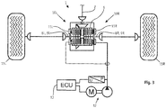
- FIG. 1 is a known from the prior art compensation unit 1 together with the system for its operation in a schematic view.
- the symmetrical basic structure described below of the compensation unit with the two coupling units 10 applies to the in FIG. 2 shown construction in the same way too.
- the letters "L” and “R” assigned to a specific reference symbol indicated in the figures stand for the respective left ("L”) or right (“R") component of the symmetrical basic structure.
- the drive power of the vehicle drive is transmitted via an input member 2, typically a cardan shaft, and an associated drive wheel 3 on a ring gear 4 and transferred from there to a left or right drive plate carrier 5, the respective axially displaceably arranged drive plates 6 are assigned rotationally fixed.
- These drive disks interact with left and right output disks 7, which in turn cooperate with a left or right output and output member 8 in a rotationally fixed and axially displaceable but rotatably arranged on a left or right output disk carrier 9.
- the left or right-hand coupling unit 10 thus formed represents a generally known multi-plate clutch.
- Both the right-hand coupling unit and the left-hand coupling unit are each associated with a preferably hydraulically actuated clutch actuator 11, wherein other clutch actuation mechanisms can also be usefully used, in particular electromechanical, electromagnetic, electrohydraulic or pneumatic clutch actuation mechanisms as an alternative to hydraulic clutch actuation.
- the coupling units are controlled and via the control value "hydraulic Pressure "for each of the clutches, the clutch pressure, so the pressing force with which the Ab- or drive plates are pressed together, influenced, so that the transmittable by the clutches torque can be adjusted selectively Manipulated variable - depending on the selected mechanism - for example, a mechanical force, current, electrical voltage or pneumatic pressure.
- the rotatably coupled to the input member 2 drive disk carrier 5 is designed as an outer disk carrier and the non-rotatably coupled to the drive wheels output disk carrier as an inner disk carrier.
- this embodiment can also be reversed.
- FIG. 1 a system for operating and controlling the left and right coupling unit is shown, in which the left and right of the two clutches 10 can be controlled independently of the driving state individually with a different pressure p L or p R.
- the manipulated variable "hydraulic pressure" are used in different heights.
- This has the advantage that the output pressure p 0 generated by a hydraulic, motor-driven pump unit 12 can optimally act on the two clutches, depending on the driving conditions, in order to assign to the left or right drive wheel exactly the drive torque or drive power that is required for the respective driving state and the desired driving behavior can be considered optimal. In this way, traction or driving dynamics can be selectively influenced in different driving situations.
- An electronic control unit 13 detects the pressures present in the system p 0 , p L and p R and controls based on stored maps and taking into account driving condition data (wheel speeds, acceleration forces, vehicle inclination, speed, steering angle, etc.) on the left and right clutch over two independently acting control valves 14 individually at.
- driving condition data wheel speeds, acceleration forces, vehicle inclination, speed, steering angle, etc.
- FIG. 2 is an alternative system for operating the otherwise opposite FIG. 1 unchanged coupling units 10 shown.
- FIG. 2 already illustrates graphically that the system represents a significant simplification. This not only dispenses with the individually different control of the left and right clutch, but it is altogether dispensed with the use of control elements such as control valves and sensors.
- the variably producible by the system manipulated variable is independent of the driving situation, always transmitted at the same level both on the left and on the right clutch driving state.
- clutch torque is variable, but always the same for both clutches.
- the invention provides the ability to equip vehicles with a switchable four-wheel drive, in which the use of a Systems, as is in FIG. 1 is shown schematically, otherwise perceived as too expensive.
- FIG. 2 When compared to the system FIG. 1 simplified system after FIG. 2 is provided in particular that the "supply" of the first and second clutch with the pressing force of the clutch plates influencing control variable without further control elements such as control valves and thus “taxless”, in the case of using a hydraulic pump so in particular without the hydraulic pump downstream individual control elements.
- the height of the manipulated variable "hydraulic pressure" is in the in FIG. 2 shown case on the pumping power of the hydraulic pump unit regulated, in particular on their variable speed with the delivery capacity. In the case of other types of clutch actuation mechanisms, this statement applies equally to the manipulated variable to be influenced.
- FIG. 3 shows an alternative embodiment of in FIG. 2 shown compensation unit.
- the two output members 8 and output plate carrier 9 share a common drive plate carrier 5, which allows a very compact design.
- the dashed line leading to the left clutch actuator 11L and the dashed line illustration of the left clutch actuator itself are intended to illustrate that this can be optionally provided. Because in the event that share both clutch sides of the compensation unit a drive plate carrier 5, a clutch actuator 11 R must be provided only on one side. On the side facing away from the clutch actuator only an axial support is provided, with which the axial coupling forces are supported.
- a disadvantage of such a configuration may be that the coupling forces with increasing number of lamellae on the side facing away from the clutch actuator side of the clutch unit does not work adequately, because with a shift of the individual blades under load high axial friction forces on the teeth occur, the axial displacement of the clutch plates counteract. If necessary, therefore, as well as in FIG. 2 optionally be used on a second clutch actuator.
Landscapes
- Engineering & Computer Science (AREA)
- General Engineering & Computer Science (AREA)
- Mechanical Engineering (AREA)
- Chemical & Material Sciences (AREA)
- Combustion & Propulsion (AREA)
- Transportation (AREA)
- Retarders (AREA)
- Hydraulic Clutches, Magnetic Clutches, Fluid Clutches, And Fluid Joints (AREA)
- Arrangement And Driving Of Transmission Devices (AREA)
- Arrangement And Mounting Of Devices That Control Transmission Of Motive Force (AREA)
Claims (12)
- Système pour commander une unité d'équilibrage (1) sans différentiel d'au moins un essieu pouvant être entraîné parfois d'un véhicule, l'unité d'équilibrage (1) présentant- un élément d'entrée (2)- un premier élément de sortie (8L), qui peut être couplé avec l'élément d'entrée (2) par un premier embrayage à friction (10L) afin de transmettre la puissance d'entraînement à une première roue motrice (15L), et- un deuxième élément de sortie (8R), qui peut être couplé avec l'élément d'entrée (2) par un deuxième embrayage à friction (10R) afin de transmettre la puissance d'entraînement à une deuxième roue motrice (15R),un dispositif de commande étant prévu au moyen duquel les couples d'embrayage transmis par le premier embrayage (10L) et le deuxième embrayage (10R) peuvent être réglés en modifiant une variable réglante, et le dispositif de commande étant réglé de telle manière que le premier embrayage (10L) et le deuxième embrayage (10R) sont commandés au même niveau avec la variable réglante identique modifiée quelles que soient les conditions de conduite, caractérisé en ce que le système comprend une pompe hydraulique (12), la variable réglante est une pression hydraulique et le système est ajusté de telle manière que la modification de la variable réglante puisse être réglée pendant le fonctionnement du véhicule, quelles que soient les conditions de conduite, et de façon ciblée en changeant la vitesse de la pompe hydraulique (12).
- Système selon la revendication précédente, caractérisé en ce qu'un actionneur d'embrayage (11L, 11R) est prévu pour l'actionnement du premier embrayage (10L) et l'actionnement du deuxième embrayage (10R) sur lequel la variable réglante agit afin d'actionner les embrayages (10L, 10 R), et qu'une seule unité de variable réglante (12) est prévue sur laquelle le niveau de la variable réglante agissant sur les deux embrayages (10L, 10R) est réglable.
- Système selon l'une des revendications précédentes, caractérisé en ce que le système est un système sans organe de commande individuel (14L, 14R) via lequel la variable réglante pour le premier embrayage (10L) pourrait être réglée à un premier niveau et la variable réglante pour le deuxième embrayage (10R) à un deuxième niveau différent du premier niveau.
- Procédé destiné à faire fonctionner une unité d'équilibrage (1) sans différentiel d'au moins un essieu pouvant être entraîné parfois d'un véhicule, l'unité d'équilibrage présentant- un élément d'entrée (2)- un premier élément de sortie (8L), qui peut être couplé avec l'élément d'entrée (2) par un premier embrayage à friction (10L) afin de transmettre la puissance d'entraînement à une première roue motrice (15L), et- un deuxième élément de sortie (8R), qui peut être couplé avec l'élément d'entrée (2) par un deuxième embrayage à friction (10R) afin de transmettre la puissance d'entraînement à une deuxième roue motrice (15R),et les couples d'embrayage du premier embrayage (10L) et du deuxième embrayage (10R) étant réglés par un dispositif de commande en modifiant la variable réglante, le premier embrayage (10L) et le deuxième embrayage (10R) étant entraînés au même niveau avec une variable réglante quelles que soient les conditions de conduite, caractérisé en ce que la variable réglante est une pression hydraulique et la variable réglante est modifiée pendant le fonctionnement du véhicule quelles que soient les conditions de conduite et de façon ciblée en changeant la vitesse de la pompe hydraulique (12).
- Procédé selon la revendication précédente, caractérisé en ce qu'un actionneur d'embrayage (11L, 11R) est prévu pour l'actionnement du premier embrayage (10L) et l'actionnement du deuxième embrayage (10R), sur lequel la variable réglante agit afin d'actionner les embrayages (10L, 10R), et qu'une seule unité de variable réglante (12) est prévue pour régler le niveau de la variable réglante agissant sur les deux embrayages (10L, 10R).
- Procédé selon l'une des revendications précédentes, caractérisé en ce que la variable réglante agit non seulement sur le premier embrayage (10L) mais également sur le deuxième embrayage (10R) sans interconnexion d'autres organes de commande individuels (14), via lesquels la variable réglante pour le premier embrayage (10L) pourrait être réglée à un premier niveau et la variable réglante pour le deuxième embrayage (10R) à un deuxième niveau différent du premier niveau.
- Procédé selon l'une des revendications précédentes, caractérisé en ce que le potentiel d'adhérence de la roue intérieure est déterminé fondamentalement sur la base du calcul de la variable réglante dans les virages.
- Procédé selon l'une des revendications précédentes, caractérisé en ce que le potentiel d'adhérence de la roue intérieure est déterminé fondamentalement sur la base du calcul de la variable réglante dans les virages en dessous d'une valeur seuil d'accélération latérale, le potentiel d'adhérence de la roue extérieure est déterminé fondamentalement sur la base du calcul de la variable réglante dans les virages en dessus de la valeur seuil d'accélération latérale.
- Procédé selon l'une des cinq revendications précédentes, caractérisées en ce qu'une détection de différents potentiels d'adhérence des roues motrices est prévue (détection µ-split) et que le potentiel d'adhérence de la roue motrice au potentiel d'adhérence le plus élevé est considéré comme déterminant pour le calcul de la variable réglante (réglage µ-high) en accélérant de la position lors du calcul de la variable réglante.
- Procédé selon l'une des six revendications précédentes, caractérisé en ce qu'à vitesse accrue du véhicule lors du calcul de la variable réglante, un réglage µ-low est prévu lors duquel le potentiel d'adhérence de la roue motrice au potentiel d'adhérence le moins élevé est considéré comme déterminant pour le calcul de la variable réglante.
- Produit de programme informatique qui permet à une unité de commande électronique (13) de réguler un système selon l'une des revendications 1 à 3, de commander l'unité d'équilibrage selon le procédé de l'une des revendications 4 à 10 lorsque l'unité de commande électronique (13) effectue des routines de programme contenues dans le code de programme du produit de programme informatique.
- Unité de commande électronique (13) destinée à la commande d'une unité d'équilibrage selon le procédé de l'une des revendications 4 à 10 avec une mémoire de programme qui est comprise dans le produit de programme informatique selon la revendication précédente.
Applications Claiming Priority (1)
| Application Number | Priority Date | Filing Date | Title |
|---|---|---|---|
| PCT/EP2013/077248 WO2015090392A1 (fr) | 2013-12-18 | 2013-12-18 | Unité d'équilibrage d'un véhicule automobile et son procédé de commande |
Publications (2)
| Publication Number | Publication Date |
|---|---|
| EP3083314A1 EP3083314A1 (fr) | 2016-10-26 |
| EP3083314B1 true EP3083314B1 (fr) | 2018-02-14 |
Family
ID=49949632
Family Applications (1)
| Application Number | Title | Priority Date | Filing Date |
|---|---|---|---|
| EP13819018.6A Active EP3083314B1 (fr) | 2013-12-18 | 2013-12-18 | Unité différentielle d'un véhicule automobile et son procédé de commande |
Country Status (5)
| Country | Link |
|---|---|
| US (1) | US10295036B2 (fr) |
| EP (1) | EP3083314B1 (fr) |
| JP (1) | JP6286052B2 (fr) |
| CN (1) | CN105916719B (fr) |
| WO (1) | WO2015090392A1 (fr) |
Families Citing this family (8)
| Publication number | Priority date | Publication date | Assignee | Title |
|---|---|---|---|---|
| JP6577046B2 (ja) | 2015-03-19 | 2019-09-18 | ジーケイエヌ・オートモーティブ・リミテッド | 自動車両の平衡装置および平衡装置を制御するための方法 |
| DE102016110915A1 (de) | 2016-06-14 | 2017-12-14 | Gkn Automotive Ltd. | Hydraulisches Kupplungsbetätigungssystem mit On-Demand Kupplungsbeölung |
| WO2018046076A1 (fr) | 2016-09-06 | 2018-03-15 | Gkn Automotive Ltd. | Système de commande hydraulique d'une unité d'entraînement d'essieu d'un véhicule à moteur et soupape de commande hydraulique et procédé pour la commander |
| WO2018149473A1 (fr) * | 2017-02-14 | 2018-08-23 | Gkn Driveline Automotive Ltd. | Articulation tournante pouvant être intégrée |
| DE102017127816A1 (de) * | 2017-11-24 | 2019-05-29 | Gkn Automotive Ltd. | Verfahren zur Steuerung eines Antriebssystems für mindestens eine Achse eines Kraftfahrzeuges |
| DE112018007803B4 (de) | 2018-07-05 | 2025-06-12 | Gkn Automotive Ltd. | Verfahren zur regelung eines antriebssystems für eine achse eines kraftfahrzeuges |
| CN109455050B (zh) * | 2018-10-22 | 2021-06-18 | 白城师范学院 | 一种水陆空机器人及其协作控制系统 |
| US11376955B2 (en) * | 2019-08-29 | 2022-07-05 | Kawasaki Motors, Ltd. | Utility vehicle |
Family Cites Families (12)
| Publication number | Priority date | Publication date | Assignee | Title |
|---|---|---|---|---|
| JP2872718B2 (ja) | 1989-12-09 | 1999-03-24 | マツダ株式会社 | 4輪駆動装置 |
| US5105901A (en) | 1989-12-09 | 1992-04-21 | Mazda Motor Corporation | Four wheel drive system |
| JPH03279027A (ja) * | 1990-03-28 | 1991-12-10 | Mazda Motor Corp | 車両の動力伝達装置 |
| DE4021747A1 (de) * | 1990-07-07 | 1992-01-16 | Gkn Automotive Ag | Antriebsanordnung |
| JP4821208B2 (ja) * | 2005-08-08 | 2011-11-24 | 日産自動車株式会社 | 車両の駆動力配分装置 |
| DE102007030091A1 (de) * | 2007-06-28 | 2008-10-02 | Getrag Driveline Systems Gmbh | Antriebsstrang für ein Kraftfahrzeug |
| US8215440B2 (en) | 2008-05-06 | 2012-07-10 | Getrag Driveline Systems, Gmbh | Drive train for a vehicle with connectable secondary axle |
| JP2010164080A (ja) * | 2009-01-13 | 2010-07-29 | Univance Corp | 車両用駆動制御装置 |
| DE102010036826B4 (de) * | 2010-08-03 | 2014-05-28 | Gkn Driveline Köping Ab | Ausgleichseinheit eines Antriebsstrangs eines Kraftfahrzeugs sowie dessen Aufbau zur verlustminimierten Bedarfsbeölung |
| GB2490427B (en) * | 2011-04-28 | 2014-04-23 | Jaguar Land Rover Ltd | Vehicle and method of controlling a vehicle |
| EP2574826B1 (fr) * | 2011-09-30 | 2014-02-26 | GKN Driveline Köping AB | Composant d'embrayage doté d'un dispositif de retenue d'huile |
| US9845006B2 (en) * | 2014-02-27 | 2017-12-19 | Nissan Motor Co., Ltd. | Clutch control device for 4-wheel drive vehicle |
-
2013
- 2013-12-18 WO PCT/EP2013/077248 patent/WO2015090392A1/fr not_active Ceased
- 2013-12-18 JP JP2016541364A patent/JP6286052B2/ja active Active
- 2013-12-18 US US15/102,319 patent/US10295036B2/en active Active
- 2013-12-18 EP EP13819018.6A patent/EP3083314B1/fr active Active
- 2013-12-18 CN CN201380081736.XA patent/CN105916719B/zh active Active
Also Published As
| Publication number | Publication date |
|---|---|
| WO2015090392A1 (fr) | 2015-06-25 |
| JP6286052B2 (ja) | 2018-02-28 |
| US20170037949A1 (en) | 2017-02-09 |
| CN105916719B (zh) | 2018-11-09 |
| CN105916719A (zh) | 2016-08-31 |
| EP3083314A1 (fr) | 2016-10-26 |
| JP2017500513A (ja) | 2017-01-05 |
| US10295036B2 (en) | 2019-05-21 |
Similar Documents
| Publication | Publication Date | Title |
|---|---|---|
| EP3083314B1 (fr) | Unité différentielle d'un véhicule automobile et son procédé de commande | |
| DE102004004335B4 (de) | Fahrwerksanordnung für ein Fahrzeug | |
| EP2221207A1 (fr) | Dispositif d'entraînement pour un essieu d'un véhicule automobile ainsi que véhicule automobile | |
| DE102008032475A1 (de) | Verfahren zum Kalibrieren einer Kupplungseinheit | |
| EP3271205B1 (fr) | Unité d'équilibrage d'un véhicule automobile et procédé de commande correspondant | |
| WO2005035295A1 (fr) | Ensemble transmission d'un vehicule toutes roues motrices avec embrayages et procede pour commander et reguler les embrayages de cet ensemble transmission | |
| EP1648729B1 (fr) | Dispositif de commande pour vehicule automobile a quatre roues motrices au moins de façon intermittente | |
| DE102006061516B4 (de) | Hydraulikanordnung zur Ansteuerung zweier Aktuatoren | |
| DE102009022240A1 (de) | Verfahren zum Klassieren einer Kupplungseinheit | |
| DE102006004315A1 (de) | Hydraulische Servolenkung | |
| DE102005021901A1 (de) | Vorrichtung und Verfahren zum Einstellen einer Übertragungsfähigkeit eines reibschlüssigen Schaltelementes | |
| EP2640616B1 (fr) | Véhicule, en particulier véhicule hybride | |
| DE102016211342A1 (de) | Lenkvorrichtung für ein Kraftfahrzeug | |
| EP1687546B1 (fr) | Dispositif de transfert de couple | |
| DE102013013693B4 (de) | Sperrdifferenzialgetriebe für eine Antriebsachse eines Kraftfahrzeugs sowie Verfahren zum Betätigen des Sperrdifferenzialgetriebes | |
| EP2828544B1 (fr) | Procédé de détermination de la quantité de remplissage | |
| DE102016220477B4 (de) | Achsantriebssystem sowie Verfahren zur Steuerung eines Achsantriebssystems | |
| DE102017204461A1 (de) | Hydrostatischer Fahrantrieb | |
| EP3378736B1 (fr) | Système d'entraînement pour véhicules à chenilles et engins de travail à chenilles et procédé de commande d'un système d'entraînement pour véhicules à chenilles et engins de travail à chenilles | |
| EP3909799B1 (fr) | Répartition du couple en fonction de l'angle de direction | |
| DE102015011855A1 (de) | Verfahren zur Reibwertadaption bei einer Kupplung | |
| DE102004004866A1 (de) | Verfahren und Anordnung zur Steuerung einer Kraftfahrzeug-Drehmomentübertragungskupplung | |
| DE102005052105A1 (de) | Hydrodynamisches System und Verfahren zur Steuerung des hydrodynamischen Systems | |
| WO2018046076A1 (fr) | Système de commande hydraulique d'une unité d'entraînement d'essieu d'un véhicule à moteur et soupape de commande hydraulique et procédé pour la commander | |
| DE102004004868A1 (de) | Verfahren und Anordnung zur Steuerung einer Kraftfahrzeug-Drehmomentübertragungskupplung |
Legal Events
| Date | Code | Title | Description |
|---|---|---|---|
| PUAI | Public reference made under article 153(3) epc to a published international application that has entered the european phase |
Free format text: ORIGINAL CODE: 0009012 |
|
| 17P | Request for examination filed |
Effective date: 20160629 |
|
| AK | Designated contracting states |
Kind code of ref document: A1 Designated state(s): AL AT BE BG CH CY CZ DE DK EE ES FI FR GB GR HR HU IE IS IT LI LT LU LV MC MK MT NL NO PL PT RO RS SE SI SK SM TR |
|
| AX | Request for extension of the european patent |
Extension state: BA ME |
|
| DAX | Request for extension of the european patent (deleted) | ||
| REG | Reference to a national code |
Ref country code: DE Ref legal event code: R079 Ref document number: 502013009421 Country of ref document: DE Free format text: PREVIOUS MAIN CLASS: B60K0023080000 Ipc: B60K0023040000 |
|
| RAP1 | Party data changed (applicant data changed or rights of an application transferred) |
Owner name: GKN AUTOMOTIVE LIMITED |
|
| RIC1 | Information provided on ipc code assigned before grant |
Ipc: B60K 23/04 20060101AFI20170629BHEP |
|
| GRAP | Despatch of communication of intention to grant a patent |
Free format text: ORIGINAL CODE: EPIDOSNIGR1 |
|
| INTG | Intention to grant announced |
Effective date: 20170824 |
|
| GRAS | Grant fee paid |
Free format text: ORIGINAL CODE: EPIDOSNIGR3 |
|
| GRAA | (expected) grant |
Free format text: ORIGINAL CODE: 0009210 |
|
| AK | Designated contracting states |
Kind code of ref document: B1 Designated state(s): AL AT BE BG CH CY CZ DE DK EE ES FI FR GB GR HR HU IE IS IT LI LT LU LV MC MK MT NL NO PL PT RO RS SE SI SK SM TR |
|
| REG | Reference to a national code |
Ref country code: GB Ref legal event code: FG4D Free format text: NOT ENGLISH |
|
| REG | Reference to a national code |
Ref country code: CH Ref legal event code: EP |
|
| REG | Reference to a national code |
Ref country code: IE Ref legal event code: FG4D Free format text: LANGUAGE OF EP DOCUMENT: GERMAN |
|
| REG | Reference to a national code |
Ref country code: DE Ref legal event code: R096 Ref document number: 502013009421 Country of ref document: DE Ref country code: AT Ref legal event code: REF Ref document number: 969618 Country of ref document: AT Kind code of ref document: T Effective date: 20180315 |
|
| REG | Reference to a national code |
Ref country code: SE Ref legal event code: TRGR |
|
| REG | Reference to a national code |
Ref country code: NL Ref legal event code: MP Effective date: 20180214 |
|
| PG25 | Lapsed in a contracting state [announced via postgrant information from national office to epo] |
Ref country code: ES Free format text: LAPSE BECAUSE OF FAILURE TO SUBMIT A TRANSLATION OF THE DESCRIPTION OR TO PAY THE FEE WITHIN THE PRESCRIBED TIME-LIMIT Effective date: 20180214 Ref country code: HR Free format text: LAPSE BECAUSE OF FAILURE TO SUBMIT A TRANSLATION OF THE DESCRIPTION OR TO PAY THE FEE WITHIN THE PRESCRIBED TIME-LIMIT Effective date: 20180214 Ref country code: FI Free format text: LAPSE BECAUSE OF FAILURE TO SUBMIT A TRANSLATION OF THE DESCRIPTION OR TO PAY THE FEE WITHIN THE PRESCRIBED TIME-LIMIT Effective date: 20180214 Ref country code: NO Free format text: LAPSE BECAUSE OF FAILURE TO SUBMIT A TRANSLATION OF THE DESCRIPTION OR TO PAY THE FEE WITHIN THE PRESCRIBED TIME-LIMIT Effective date: 20180514 Ref country code: CY Free format text: LAPSE BECAUSE OF FAILURE TO SUBMIT A TRANSLATION OF THE DESCRIPTION OR TO PAY THE FEE WITHIN THE PRESCRIBED TIME-LIMIT Effective date: 20180214 Ref country code: LT Free format text: LAPSE BECAUSE OF FAILURE TO SUBMIT A TRANSLATION OF THE DESCRIPTION OR TO PAY THE FEE WITHIN THE PRESCRIBED TIME-LIMIT Effective date: 20180214 Ref country code: NL Free format text: LAPSE BECAUSE OF FAILURE TO SUBMIT A TRANSLATION OF THE DESCRIPTION OR TO PAY THE FEE WITHIN THE PRESCRIBED TIME-LIMIT Effective date: 20180214 |
|
| PG25 | Lapsed in a contracting state [announced via postgrant information from national office to epo] |
Ref country code: RS Free format text: LAPSE BECAUSE OF FAILURE TO SUBMIT A TRANSLATION OF THE DESCRIPTION OR TO PAY THE FEE WITHIN THE PRESCRIBED TIME-LIMIT Effective date: 20180214 Ref country code: LV Free format text: LAPSE BECAUSE OF FAILURE TO SUBMIT A TRANSLATION OF THE DESCRIPTION OR TO PAY THE FEE WITHIN THE PRESCRIBED TIME-LIMIT Effective date: 20180214 Ref country code: GR Free format text: LAPSE BECAUSE OF FAILURE TO SUBMIT A TRANSLATION OF THE DESCRIPTION OR TO PAY THE FEE WITHIN THE PRESCRIBED TIME-LIMIT Effective date: 20180515 Ref country code: BG Free format text: LAPSE BECAUSE OF FAILURE TO SUBMIT A TRANSLATION OF THE DESCRIPTION OR TO PAY THE FEE WITHIN THE PRESCRIBED TIME-LIMIT Effective date: 20180514 |
|
| PG25 | Lapsed in a contracting state [announced via postgrant information from national office to epo] |
Ref country code: MT Free format text: LAPSE BECAUSE OF FAILURE TO SUBMIT A TRANSLATION OF THE DESCRIPTION OR TO PAY THE FEE WITHIN THE PRESCRIBED TIME-LIMIT Effective date: 20180214 |
|
| PG25 | Lapsed in a contracting state [announced via postgrant information from national office to epo] |
Ref country code: RO Free format text: LAPSE BECAUSE OF FAILURE TO SUBMIT A TRANSLATION OF THE DESCRIPTION OR TO PAY THE FEE WITHIN THE PRESCRIBED TIME-LIMIT Effective date: 20180214 Ref country code: AL Free format text: LAPSE BECAUSE OF FAILURE TO SUBMIT A TRANSLATION OF THE DESCRIPTION OR TO PAY THE FEE WITHIN THE PRESCRIBED TIME-LIMIT Effective date: 20180214 Ref country code: IT Free format text: LAPSE BECAUSE OF FAILURE TO SUBMIT A TRANSLATION OF THE DESCRIPTION OR TO PAY THE FEE WITHIN THE PRESCRIBED TIME-LIMIT Effective date: 20180214 Ref country code: EE Free format text: LAPSE BECAUSE OF FAILURE TO SUBMIT A TRANSLATION OF THE DESCRIPTION OR TO PAY THE FEE WITHIN THE PRESCRIBED TIME-LIMIT Effective date: 20180214 Ref country code: PL Free format text: LAPSE BECAUSE OF FAILURE TO SUBMIT A TRANSLATION OF THE DESCRIPTION OR TO PAY THE FEE WITHIN THE PRESCRIBED TIME-LIMIT Effective date: 20180214 |
|
| REG | Reference to a national code |
Ref country code: DE Ref legal event code: R097 Ref document number: 502013009421 Country of ref document: DE |
|
| PG25 | Lapsed in a contracting state [announced via postgrant information from national office to epo] |
Ref country code: SM Free format text: LAPSE BECAUSE OF FAILURE TO SUBMIT A TRANSLATION OF THE DESCRIPTION OR TO PAY THE FEE WITHIN THE PRESCRIBED TIME-LIMIT Effective date: 20180214 Ref country code: DK Free format text: LAPSE BECAUSE OF FAILURE TO SUBMIT A TRANSLATION OF THE DESCRIPTION OR TO PAY THE FEE WITHIN THE PRESCRIBED TIME-LIMIT Effective date: 20180214 Ref country code: SK Free format text: LAPSE BECAUSE OF FAILURE TO SUBMIT A TRANSLATION OF THE DESCRIPTION OR TO PAY THE FEE WITHIN THE PRESCRIBED TIME-LIMIT Effective date: 20180214 Ref country code: CZ Free format text: LAPSE BECAUSE OF FAILURE TO SUBMIT A TRANSLATION OF THE DESCRIPTION OR TO PAY THE FEE WITHIN THE PRESCRIBED TIME-LIMIT Effective date: 20180214 |
|
| PLBE | No opposition filed within time limit |
Free format text: ORIGINAL CODE: 0009261 |
|
| STAA | Information on the status of an ep patent application or granted ep patent |
Free format text: STATUS: NO OPPOSITION FILED WITHIN TIME LIMIT |
|
| 26N | No opposition filed |
Effective date: 20181115 |
|
| PG25 | Lapsed in a contracting state [announced via postgrant information from national office to epo] |
Ref country code: SI Free format text: LAPSE BECAUSE OF FAILURE TO SUBMIT A TRANSLATION OF THE DESCRIPTION OR TO PAY THE FEE WITHIN THE PRESCRIBED TIME-LIMIT Effective date: 20180214 |
|
| REG | Reference to a national code |
Ref country code: CH Ref legal event code: PL |
|
| GBPC | Gb: european patent ceased through non-payment of renewal fee |
Effective date: 20181218 |
|
| PG25 | Lapsed in a contracting state [announced via postgrant information from national office to epo] |
Ref country code: MC Free format text: LAPSE BECAUSE OF FAILURE TO SUBMIT A TRANSLATION OF THE DESCRIPTION OR TO PAY THE FEE WITHIN THE PRESCRIBED TIME-LIMIT Effective date: 20180214 Ref country code: LU Free format text: LAPSE BECAUSE OF NON-PAYMENT OF DUE FEES Effective date: 20181218 |
|
| REG | Reference to a national code |
Ref country code: IE Ref legal event code: MM4A |
|
| REG | Reference to a national code |
Ref country code: BE Ref legal event code: MM Effective date: 20181231 |
|
| PG25 | Lapsed in a contracting state [announced via postgrant information from national office to epo] |
Ref country code: FR Free format text: LAPSE BECAUSE OF NON-PAYMENT OF DUE FEES Effective date: 20181231 Ref country code: IE Free format text: LAPSE BECAUSE OF NON-PAYMENT OF DUE FEES Effective date: 20181218 |
|
| PG25 | Lapsed in a contracting state [announced via postgrant information from national office to epo] |
Ref country code: BE Free format text: LAPSE BECAUSE OF NON-PAYMENT OF DUE FEES Effective date: 20181231 |
|
| PG25 | Lapsed in a contracting state [announced via postgrant information from national office to epo] |
Ref country code: CH Free format text: LAPSE BECAUSE OF NON-PAYMENT OF DUE FEES Effective date: 20181231 Ref country code: GB Free format text: LAPSE BECAUSE OF NON-PAYMENT OF DUE FEES Effective date: 20181218 Ref country code: LI Free format text: LAPSE BECAUSE OF NON-PAYMENT OF DUE FEES Effective date: 20181231 |
|
| PG25 | Lapsed in a contracting state [announced via postgrant information from national office to epo] |
Ref country code: TR Free format text: LAPSE BECAUSE OF FAILURE TO SUBMIT A TRANSLATION OF THE DESCRIPTION OR TO PAY THE FEE WITHIN THE PRESCRIBED TIME-LIMIT Effective date: 20180214 |
|
| PG25 | Lapsed in a contracting state [announced via postgrant information from national office to epo] |
Ref country code: PT Free format text: LAPSE BECAUSE OF FAILURE TO SUBMIT A TRANSLATION OF THE DESCRIPTION OR TO PAY THE FEE WITHIN THE PRESCRIBED TIME-LIMIT Effective date: 20180214 |
|
| PG25 | Lapsed in a contracting state [announced via postgrant information from national office to epo] |
Ref country code: HU Free format text: LAPSE BECAUSE OF FAILURE TO SUBMIT A TRANSLATION OF THE DESCRIPTION OR TO PAY THE FEE WITHIN THE PRESCRIBED TIME-LIMIT; INVALID AB INITIO Effective date: 20131218 Ref country code: MK Free format text: LAPSE BECAUSE OF NON-PAYMENT OF DUE FEES Effective date: 20180214 |
|
| PG25 | Lapsed in a contracting state [announced via postgrant information from national office to epo] |
Ref country code: IS Free format text: LAPSE BECAUSE OF FAILURE TO SUBMIT A TRANSLATION OF THE DESCRIPTION OR TO PAY THE FEE WITHIN THE PRESCRIBED TIME-LIMIT Effective date: 20180614 |
|
| PGFP | Annual fee paid to national office [announced via postgrant information from national office to epo] |
Ref country code: SE Payment date: 20231219 Year of fee payment: 11 Ref country code: AT Payment date: 20231214 Year of fee payment: 11 |
|
| REG | Reference to a national code |
Ref country code: DE Ref legal event code: R082 Ref document number: 502013009421 Country of ref document: DE Representative=s name: KBN IP PATENTANWAELTE PARTNERSCHAFT MBB, DE |
|
| REG | Reference to a national code |
Ref country code: SE Ref legal event code: EUG |
|
| REG | Reference to a national code |
Ref country code: AT Ref legal event code: MM01 Ref document number: 969618 Country of ref document: AT Kind code of ref document: T Effective date: 20241218 |
|
| PG25 | Lapsed in a contracting state [announced via postgrant information from national office to epo] |
Ref country code: AT Free format text: LAPSE BECAUSE OF NON-PAYMENT OF DUE FEES Effective date: 20241218 |
|
| PGFP | Annual fee paid to national office [announced via postgrant information from national office to epo] |
Ref country code: DE Payment date: 20251222 Year of fee payment: 13 |