EP3083314B1 - Differential unit of a motor vehicle and method for controlling same - Google Patents
Differential unit of a motor vehicle and method for controlling same Download PDFInfo
- Publication number
- EP3083314B1 EP3083314B1 EP13819018.6A EP13819018A EP3083314B1 EP 3083314 B1 EP3083314 B1 EP 3083314B1 EP 13819018 A EP13819018 A EP 13819018A EP 3083314 B1 EP3083314 B1 EP 3083314B1
- Authority
- EP
- European Patent Office
- Prior art keywords
- clutch
- correcting variable
- height
- friction
- drive
- Prior art date
- Legal status (The legal status is an assumption and is not a legal conclusion. Google has not performed a legal analysis and makes no representation as to the accuracy of the status listed.)
- Active
Links
Images

Classifications
-
- F—MECHANICAL ENGINEERING; LIGHTING; HEATING; WEAPONS; BLASTING
- F16—ENGINEERING ELEMENTS AND UNITS; GENERAL MEASURES FOR PRODUCING AND MAINTAINING EFFECTIVE FUNCTIONING OF MACHINES OR INSTALLATIONS; THERMAL INSULATION IN GENERAL
- F16H—GEARING
- F16H48/00—Differential gearings
- F16H48/12—Differential gearings without gears having orbital motion
- F16H48/19—Differential gearings without gears having orbital motion consisting of two linked clutches
-
- B—PERFORMING OPERATIONS; TRANSPORTING
- B60—VEHICLES IN GENERAL
- B60K—ARRANGEMENT OR MOUNTING OF PROPULSION UNITS OR OF TRANSMISSIONS IN VEHICLES; ARRANGEMENT OR MOUNTING OF PLURAL DIVERSE PRIME-MOVERS IN VEHICLES; AUXILIARY DRIVES FOR VEHICLES; INSTRUMENTATION OR DASHBOARDS FOR VEHICLES; ARRANGEMENTS IN CONNECTION WITH COOLING, AIR INTAKE, GAS EXHAUST OR FUEL SUPPLY OF PROPULSION UNITS IN VEHICLES
- B60K23/00—Arrangement or mounting of control devices for vehicle transmissions, or parts thereof, not otherwise provided for
- B60K23/04—Arrangement or mounting of control devices for vehicle transmissions, or parts thereof, not otherwise provided for for differential gearing
-
- F—MECHANICAL ENGINEERING; LIGHTING; HEATING; WEAPONS; BLASTING
- F16—ENGINEERING ELEMENTS AND UNITS; GENERAL MEASURES FOR PRODUCING AND MAINTAINING EFFECTIVE FUNCTIONING OF MACHINES OR INSTALLATIONS; THERMAL INSULATION IN GENERAL
- F16H—GEARING
- F16H48/00—Differential gearings
- F16H48/20—Arrangements for suppressing or influencing the differential action, e.g. locking devices
- F16H48/22—Arrangements for suppressing or influencing the differential action, e.g. locking devices using friction clutches or brakes
-
- B—PERFORMING OPERATIONS; TRANSPORTING
- B60—VEHICLES IN GENERAL
- B60K—ARRANGEMENT OR MOUNTING OF PROPULSION UNITS OR OF TRANSMISSIONS IN VEHICLES; ARRANGEMENT OR MOUNTING OF PLURAL DIVERSE PRIME-MOVERS IN VEHICLES; AUXILIARY DRIVES FOR VEHICLES; INSTRUMENTATION OR DASHBOARDS FOR VEHICLES; ARRANGEMENTS IN CONNECTION WITH COOLING, AIR INTAKE, GAS EXHAUST OR FUEL SUPPLY OF PROPULSION UNITS IN VEHICLES
- B60K23/00—Arrangement or mounting of control devices for vehicle transmissions, or parts thereof, not otherwise provided for
- B60K23/04—Arrangement or mounting of control devices for vehicle transmissions, or parts thereof, not otherwise provided for for differential gearing
- B60K2023/043—Control means for varying left-right torque distribution, e.g. torque vectoring
-
- B—PERFORMING OPERATIONS; TRANSPORTING
- B60—VEHICLES IN GENERAL
- B60Y—INDEXING SCHEME RELATING TO ASPECTS CROSS-CUTTING VEHICLE TECHNOLOGY
- B60Y2300/00—Purposes or special features of road vehicle drive control systems
- B60Y2300/80—Control of differentials
- B60Y2300/82—Torque vectoring
-
- B—PERFORMING OPERATIONS; TRANSPORTING
- B60—VEHICLES IN GENERAL
- B60Y—INDEXING SCHEME RELATING TO ASPECTS CROSS-CUTTING VEHICLE TECHNOLOGY
- B60Y2400/00—Special features of vehicle units
- B60Y2400/80—Differentials
- B60Y2400/804—Torque vectoring arrangements
Definitions
- the invention relates to a system for controlling a differential-free, clutch-controlled compensation unit of a motor vehicle, in particular a passenger car, according to the preamble of claim 1, in particular a transverse compensation unit, and a method for controlling such a compensation unit according to the preamble of claim 5.
- the invention In addition, a computer program product that causes an electronic control unit for controlling such a compensation unit to control the compensation unit according to the inventive method.
- Such compensation units and systems and methods for their operation are for example from EP 2 116 411 A1 , of the DE 10 2007 030 091 A1 or the DE 40 39 391 A1 known.
- two separately controllable control valves are used to selectively control the first and second clutch with a certain control pressure to affect the condition of the state of the respective coupling to the associated drive wheel clutch torque.
- the plate sets are acted upon by a common actuator with the same actuating forces.
- This disclosure describes as an actuating device only a mechanical spreading mechanism in detail, which is to be regarded as disadvantageous, inter alia, due to its mechanical complexity, its space requirement and its only one-sided action on the dual clutch assembly. 0b and if so, how the dual clutch arrangement can be driven depending on the driving state, the disclosure leaves open, however.
- the object of the invention is therefore to provide a system for operating a differential-free compensation unit of the type mentioned and a method for operating such a compensation unit, which are significantly reduced in complexity over the known systems and methods and still satisfactory in all essential aspects drive concept represent.
- a drive concept with shiftable four-wheel drive is envisaged.
- the aim is to find a way of "upgrading" the known systems and methods by reducing the technical effort, among other things also with the aim of making the systems and methods attractive for vehicle manufacturers of vehicles below the premium segment.
- the system comprises a hydraulic pump
- the manipulated variable is hydraulic pressure and the system is set up such that the change in the manipulated variable during vehicle operation is set as a function of the driving state and specifically via a change in the rotational speed of the hydraulic pump.
- the manipulated variable is hydraulic pressure and the change in the manipulated variable during vehicle operation is dependent on driving condition and targeted by changing the speed of a hydraulic pump.
- first clutch and the second clutch can be adjusted by changing a manipulated variable during vehicle operation depending on driving condition and targeted to transmit a specific rotational or clutch torque
- the responsible for the transmittable clutch torque manipulated variable is variable such that the clutch torque transmittable by the clutches can both be adjusted such that no slippage occurs (the clutches are closed at full engagement force, the maximum clutch torque provided is transmittable), and can be adjusted to provide infinite slip (the clutches are open, it) no significant clutch torque is transmitted), as well as can be selectively adjusted so that a lying between the two aforementioned limit states clutch slip on at least one clutch occurs (the clutches are not closed with full engagement force but also not fully open in order to selectively generate a specific clutch torque on at least one of the two clutches or to selectively allow a limited slip).
- a separate clutch actuator is preferably provided, on which the manipulated variable acts to actuate the clutches.
- the setting of the height of the acting on both clutches control variable is preferably carried out via a single manipulated variable unit.
- the manipulated variable unit is the unit that provides the manipulated variable for actuating the clutch actuators.
- the manipulated variable unit is a hydraulic pump that provides hydraulic pressure as a manipulated variable.
- the system includes a variable speed hydraulic pump and the manipulated variable is changed by changing the speed of the hydraulic pump.
- This embodiment enables a central generation and change of the manipulated variable. Since pressure can also largely lossless and "even transfer” evenly, it is ensured that the manipulated variable is always identical on both clutches, so always and regardless of the driving situation always the same pressure applied to each of the two clutches.
- the pressure generated by the hydraulic pump is therefore forwarded to the first clutch and also to the second clutch without the interposition of further pressure control valves arranged downstream of the hydraulic pump.
- the drive train braces when cornering which requires a speed compensation between the inside and the outside drive wheel.
- the system or the method can also be used to specifically assist the driver in critical driving situations or to deliberately avoid critical driving situations.
- the data usually lying on the CAN bus of the vehicle such as wheel speeds or steering angle or other relevant driving state data, are read in and included in the calculation of the clutch actuation force required in the respective driving state.
- the calculation of the manipulated variable during cornering is based on the traction potential of the inside drive wheel.
- the clutch driving the bend-outward drive wheel permits slippage in order to avoid distortion of the drive train.
- the calculation of the manipulated variable during cornering is based on the traction potential of the inside wheel only as long as a certain lateral acceleration threshold is not exceeded. Above the transverse acceleration threshold value, the traction potential of the curve-outside wheel is then used as the basis for calculating the manipulated variable when cornering. This increases traction and allows higher cornering speeds.
- ⁇ -split detection When accelerating from a standstill, a system for detecting different traction potentials of the drive wheels can be used ( ⁇ -split detection), in which the calculation of the manipulated variable is largely dependent on the traction potential of the drive wheel oriented with the higher traction potential ( ⁇ -high control).
- the balancing unit would act as a limited slip differential.
- the manipulated variable may be calculated a ⁇ -high control are superimposed by a ⁇ -low control, in which the traction potential of the drive wheel with the lower traction potential is decisive for the calculation of the manipulated variable.
- a ⁇ -low control for particularly higher vehicle speeds for example greater than 50 km / h
- the compensation unit per se and a drive train with such a compensation unit are considered, each having a system for operating the compensation unit as explained above and below.
- an electronic control unit (ECU) in whose program memory a computer program product stored for carrying out the method explained above and below is set up is considered to belong to the invention.
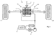
- FIG. 1 is a known from the prior art compensation unit 1 together with the system for its operation in a schematic view.
- the symmetrical basic structure described below of the compensation unit with the two coupling units 10 applies to the in FIG. 2 shown construction in the same way too.
- the letters "L” and “R” assigned to a specific reference symbol indicated in the figures stand for the respective left ("L”) or right (“R") component of the symmetrical basic structure.
- the drive power of the vehicle drive is transmitted via an input member 2, typically a cardan shaft, and an associated drive wheel 3 on a ring gear 4 and transferred from there to a left or right drive plate carrier 5, the respective axially displaceably arranged drive plates 6 are assigned rotationally fixed.
- These drive disks interact with left and right output disks 7, which in turn cooperate with a left or right output and output member 8 in a rotationally fixed and axially displaceable but rotatably arranged on a left or right output disk carrier 9.
- the left or right-hand coupling unit 10 thus formed represents a generally known multi-plate clutch.
- Both the right-hand coupling unit and the left-hand coupling unit are each associated with a preferably hydraulically actuated clutch actuator 11, wherein other clutch actuation mechanisms can also be usefully used, in particular electromechanical, electromagnetic, electrohydraulic or pneumatic clutch actuation mechanisms as an alternative to hydraulic clutch actuation.
- the coupling units are controlled and via the control value "hydraulic Pressure "for each of the clutches, the clutch pressure, so the pressing force with which the Ab- or drive plates are pressed together, influenced, so that the transmittable by the clutches torque can be adjusted selectively Manipulated variable - depending on the selected mechanism - for example, a mechanical force, current, electrical voltage or pneumatic pressure.
- the rotatably coupled to the input member 2 drive disk carrier 5 is designed as an outer disk carrier and the non-rotatably coupled to the drive wheels output disk carrier as an inner disk carrier.
- this embodiment can also be reversed.
- FIG. 1 a system for operating and controlling the left and right coupling unit is shown, in which the left and right of the two clutches 10 can be controlled independently of the driving state individually with a different pressure p L or p R.
- the manipulated variable "hydraulic pressure" are used in different heights.
- This has the advantage that the output pressure p 0 generated by a hydraulic, motor-driven pump unit 12 can optimally act on the two clutches, depending on the driving conditions, in order to assign to the left or right drive wheel exactly the drive torque or drive power that is required for the respective driving state and the desired driving behavior can be considered optimal. In this way, traction or driving dynamics can be selectively influenced in different driving situations.
- An electronic control unit 13 detects the pressures present in the system p 0 , p L and p R and controls based on stored maps and taking into account driving condition data (wheel speeds, acceleration forces, vehicle inclination, speed, steering angle, etc.) on the left and right clutch over two independently acting control valves 14 individually at.
- driving condition data wheel speeds, acceleration forces, vehicle inclination, speed, steering angle, etc.
- FIG. 2 is an alternative system for operating the otherwise opposite FIG. 1 unchanged coupling units 10 shown.
- FIG. 2 already illustrates graphically that the system represents a significant simplification. This not only dispenses with the individually different control of the left and right clutch, but it is altogether dispensed with the use of control elements such as control valves and sensors.
- the variably producible by the system manipulated variable is independent of the driving situation, always transmitted at the same level both on the left and on the right clutch driving state.
- clutch torque is variable, but always the same for both clutches.
- the invention provides the ability to equip vehicles with a switchable four-wheel drive, in which the use of a Systems, as is in FIG. 1 is shown schematically, otherwise perceived as too expensive.
- FIG. 2 When compared to the system FIG. 1 simplified system after FIG. 2 is provided in particular that the "supply" of the first and second clutch with the pressing force of the clutch plates influencing control variable without further control elements such as control valves and thus “taxless”, in the case of using a hydraulic pump so in particular without the hydraulic pump downstream individual control elements.
- the height of the manipulated variable "hydraulic pressure" is in the in FIG. 2 shown case on the pumping power of the hydraulic pump unit regulated, in particular on their variable speed with the delivery capacity. In the case of other types of clutch actuation mechanisms, this statement applies equally to the manipulated variable to be influenced.
- FIG. 3 shows an alternative embodiment of in FIG. 2 shown compensation unit.
- the two output members 8 and output plate carrier 9 share a common drive plate carrier 5, which allows a very compact design.
- the dashed line leading to the left clutch actuator 11L and the dashed line illustration of the left clutch actuator itself are intended to illustrate that this can be optionally provided. Because in the event that share both clutch sides of the compensation unit a drive plate carrier 5, a clutch actuator 11 R must be provided only on one side. On the side facing away from the clutch actuator only an axial support is provided, with which the axial coupling forces are supported.
- a disadvantage of such a configuration may be that the coupling forces with increasing number of lamellae on the side facing away from the clutch actuator side of the clutch unit does not work adequately, because with a shift of the individual blades under load high axial friction forces on the teeth occur, the axial displacement of the clutch plates counteract. If necessary, therefore, as well as in FIG. 2 optionally be used on a second clutch actuator.
Landscapes
- Engineering & Computer Science (AREA)
- General Engineering & Computer Science (AREA)
- Mechanical Engineering (AREA)
- Chemical & Material Sciences (AREA)
- Combustion & Propulsion (AREA)
- Transportation (AREA)
- Retarders (AREA)
- Hydraulic Clutches, Magnetic Clutches, Fluid Clutches, And Fluid Joints (AREA)
- Arrangement And Driving Of Transmission Devices (AREA)
- Arrangement And Mounting Of Devices That Control Transmission Of Motive Force (AREA)
Description
Die Erfindung betrifft ein System zur Ansteuerung einer differentiallosen, kupplungsgesteuerten Ausgleichseinheit eines Kraftfahrzeugs, insbesondere eines Personenkraftwagens, nach dem Oberbegriff des Anspruchs 1, insbesondere eine Quer-Ausgleichseinheit, sowie ein Verfahren zur Steuerung einer solchen Ausgleichseinheit nach dem Oberbegriff des Anspruchs 5. Die Erfindung betrifft außerdem ein Computerprogrammprodukt, das eine elektronische Steuereinheit zur Steuerung einer derartigen Ausgleichseinheit dazu veranlasst, die Ausgleichseinheit nach dem erfindungsgemäßen Verfahren anzusteuern.The invention relates to a system for controlling a differential-free, clutch-controlled compensation unit of a motor vehicle, in particular a passenger car, according to the preamble of
Derartige Ausgleichseinheiten und Systeme und Verfahren zu deren Betrieb sind zum Beispiel aus der
Nachteilig an den vorstehend genannten Systemen und Verfahren ist allerdings deren Komplexität. Sie erfordern komplexe und potentiell störungsanfällige Hard- und Software. Der Entwicklungs- und Applikationsaufwand bei einem Fahrzeug ist außerordentlich hoch. Berücksichtigt man ferner, dass derartige Systeme und Verfahren in der Regel als Allradmodule für Fahrzeuge mit abschalt- bzw. zuschaltbarem Allradantrieb vorgesehen werden und der tatsächliche Fahranteil im Allradbetrieb während der Lebensdauer eines Fahrzeugs typischerweise sehr gering ist, wird der Aufwand für die Entwicklung- und Applikation eines solchen Systems und Verfahrens von den Herstellern nicht selten für zu hoch und für zu kostspielig angesehen. Dies gilt insbesondere für Hersteller von Fahrzeugen unterhalb des Premiumsegments und von Fahrzeugtypen, die nicht aufgrund ihrer Bestimmung besonderen Bedarf an derartig komplexen Systemen haben, wie es zum Beispiel bei Geländefahrzeugen der Fall sein kann.However, a disadvantage of the above-mentioned systems and methods is their complexity. They require complex and potentially fault-prone hardware and software. The development and application effort in a vehicle is extremely high. Considering further that such systems and methods are typically provided as four-wheel modules for vehicles with shut-off or selectable four-wheel drive and the actual driving proportion in four-wheel drive during the life of a vehicle typically is very low, the effort for the development and application of such a system and method by the manufacturers is often considered to be too high and too expensive. This applies in particular to manufacturers of vehicles below the premium segment and to vehicle types which, because of their intended purpose, do not have a special need for such complex systems as may be the case, for example, with all-terrain vehicles.
Um einen einfacheren Aufbau und einfachere Regelungsmechanismen zu ermöglichen, sieht eine in der
Aufgabe der Erfindung ist es daher, ein System zum Betreiben einer differentiallosen Ausgleichseinheit der eingangs genannten Art und ein Verfahren zum Betreiben einer solchen Ausgleichseinheit anzugeben, die in ihrer Komplexität gegenüber den bekannten Systemen und Verfahren deutlich reduziert sind und trotzdem ein in allen wesentlichen Belangen zufriedenstellendes Antriebskonzept darstellen. Insbesondere wird ein Antriebskonzept mit zuschaltbaren Allradantrieb ins Auge gefasst. Es soll ein Weg gefunden werden, die bekannten Systeme und Verfahren durch Reduzierung des technischen Aufwands "abzurüsten", unter anderem auch mit dem Ziel, die Systeme und Verfahren auch für Fahrzeughersteller von Fahrzeugen unterhalb des Premiumsegments attraktiv zu machen.The object of the invention is therefore to provide a system for operating a differential-free compensation unit of the type mentioned and a method for operating such a compensation unit, which are significantly reduced in complexity over the known systems and methods and still satisfactory in all essential aspects drive concept represent. In particular, a drive concept with shiftable four-wheel drive is envisaged. The aim is to find a way of "upgrading" the known systems and methods by reducing the technical effort, among other things also with the aim of making the systems and methods attractive for vehicle manufacturers of vehicles below the premium segment.
Diese Aufgabe wird bezüglich des Systems zum Betreiben einer Ausgleichseinheit dadurch gelöst, dass das System eine Hydraulikpumpe umfasst, die Stellgröße hydraulischer Druck ist und das System derart eingerichtet ist, dass die Veränderung der Stellgröße während des Fahrzeugbetriebs fahrzustandsabhängig und gezielt über eine Änderung der Drehzahl der Hydraulikpumpe einstellt wird. Auch hinsichtlich des Verfahrens zum Betreiben einer Ausgleichseinheit ist erfindungsgemäß vorgesehen, dass die Stellgröße hydraulischer Druck ist und die Veränderung der Stellgröße während des Fahrzeugbetriebs fahrzustandsabhängig und gezielt über die Änderung der Drehzahl einer Hydraulikpumpe erfolgt.This object is achieved with respect to the system for operating a compensation unit in that the system comprises a hydraulic pump, the manipulated variable is hydraulic pressure and the system is set up such that the change in the manipulated variable during vehicle operation is set as a function of the driving state and specifically via a change in the rotational speed of the hydraulic pump. Also with regard to the method for operating a compensation unit is provided according to the invention that the manipulated variable is hydraulic pressure and the change in the manipulated variable during vehicle operation is dependent on driving condition and targeted by changing the speed of a hydraulic pump.
Dass die erste Kupplung und die zweite Kupplung durch Veränderung einer Stellgröße während des Fahrzeugbetriebs fahrzustandsabhängig und gezielt eingestellt werden können, um ein bestimmtes Dreh- bzw. Kupplungsmoment übertragen zu können, bedeutet, dass die für das übertragbare Kupplungsmoment zuständige Stellgröße derart veränderlich ist, dass das von den Kupplungen übertragbare Kupplungsmoment sowohl derart eingestellt werden kann, dass kein Schlupf auftritt (die Kupplungen sind mit voller Einrückkraft geschlossen, das maximal vorgesehene Kupplungsmoment ist übertragbar), als auch derart eingestellt werden kann, dass unendlich Schlupf auftritt (die Kupplungen sind geöffnet, es wird kein nennenswertes Kupplungsmoment übertragen), als auch gezielt derart eingestellt werden kann, das ein zwischen den beiden vorstehend genannten Grenzzuständen liegender Kupplungsschlupf an zumindest einer Kupplung auftritt (die Kupplungen sind nicht mit voller Einrückkraft geschlossen aber auch nicht voll geöffnet, um an zumindest einer der beiden Kupplungen gezielt ein bestimmtes Kupplungsmoment zu generieren oder gezielt einen begrenzten Schlupf zuzulassen).The fact that the first clutch and the second clutch can be adjusted by changing a manipulated variable during vehicle operation depending on driving condition and targeted to transmit a specific rotational or clutch torque, means that the responsible for the transmittable clutch torque manipulated variable is variable such that the clutch torque transmittable by the clutches can both be adjusted such that no slippage occurs (the clutches are closed at full engagement force, the maximum clutch torque provided is transmittable), and can be adjusted to provide infinite slip (the clutches are open, it) no significant clutch torque is transmitted), as well as can be selectively adjusted so that a lying between the two aforementioned limit states clutch slip on at least one clutch occurs (the clutches are not closed with full engagement force but also not fully open in order to selectively generate a specific clutch torque on at least one of the two clutches or to selectively allow a limited slip).
Das vorstehend beschriebene System bzw. das vorstehend beschriebene Verfahren vereinfacht die aus dem Stand der Technik bekannten Systeme erheblich. Zum einen können zusätzlich Steuerungselemente wie Drucksteuerventile und ähnliches entfallen. Auch muss die zu entwickelnde Steuersoftware nicht mehr die Ansteuerung von getrennten Steuergliedern gewährleisten können und ein Großteil der bisher einzusetzenden Messtechnik entfällt. Aus demselben Grund wird auch die Applikation eines solchen Systems im Fahrzeug wesentlich einfacher, weil für die verschiedenen Fahrzustände keine Drehmomentverteilungen mehr zu berücksichtigen sind, bei denen beide Kupplungen und damit beide Antriebsräder einer Achse unterschiedlich angesteuert werden.The system described above or the method described above considerably simplifies the systems known from the prior art. On the one hand, additional control elements such as pressure control valves and the like can be omitted. Also, the control software to be developed no longer has to be able to ensure the control of separate control elements and a large part of the previously used measuring technology is eliminated. For the same reason, the application of such a system in the vehicle is much easier, because no torque distributions for the different driving conditions more are considered, in which both clutches and thus both drive wheels of an axle are controlled differently.
Zur Betätigung der ersten Kupplung und zur Betätigung der zweiten Kupplung ist bevorzugt jeweils ein gesonderter Kupplungsaktuator vorgesehen, auf den die Stellgröße wirkt, um die Kupplungen zu betätigen. Die Einstellung der Höhe der auf beide Kupplungen wirkenden Stellgröße erfolgt dabei bevorzugt über eine einzige Stellgrößeneinheit. Die Stellgrößeneinheitist die Einheit, die die Stellgröße zur Betätigung der Kupplungsaktuatoren zur Verfügung stellt. Die Stellgrößeneinheit ist eine Hydraulikpumpe, die hydraulischen Druck als Stellgröße zur Verfügung stellt.To actuate the first clutch and to actuate the second clutch, a separate clutch actuator is preferably provided, on which the manipulated variable acts to actuate the clutches. The setting of the height of the acting on both clutches control variable is preferably carried out via a single manipulated variable unit. The manipulated variable unit is the unit that provides the manipulated variable for actuating the clutch actuators. The manipulated variable unit is a hydraulic pump that provides hydraulic pressure as a manipulated variable.
Das System umfasst eine drehzahlgeregelte Hydraulikpumpe und die Stellgrößenveränderung erfolgt über die Änderung der Drehzahl der Hydraulikpumpe. Diese Ausgestaltung ermöglicht eine zentrale Erzeugung und Veränderung der Stellgröße. Da Druck außerdem weitgehend verlustfrei und insbesondere gleichmäßig "übertragen" werden kann, ist gewährleistet, dass die Stellgröße an beiden Kupplungen stets identisch ist, also stets und unabhängig von der Fahrsituation immer der gleiche Druck an jeder der beiden Kupplungen anliegt.The system includes a variable speed hydraulic pump and the manipulated variable is changed by changing the speed of the hydraulic pump. This embodiment enables a central generation and change of the manipulated variable. Since pressure can also largely lossless and "even transfer" evenly, it is ensured that the manipulated variable is always identical on both clutches, so always and regardless of the driving situation always the same pressure applied to each of the two clutches.
Die vorstehenden Ausführungen verdeutlichen, dass das System ein System ohne Individualsteuerglieder ist, über die die Stellgröße für die erste Kupplung in einer ersten Höhe und die Stellgröße für die zweite Kupplung in einer von der ersten Höhe unterschiedlichen zweiten Höhe kupplungsindividuell bereitgestellt werden könnte, wenn diese denn vorgesehen wären. Besonders dieser bewusste Verzicht auf Individualsteuerglieder, insbesondere der Verzicht auf für jede Kupplung gesondert vorzusehende hydraulische Drucksteuerventile, und damit der Verzicht auf die notwendige separate und individuelle Ansteuerung derartiger Steuerglieder ist es, mit dem eine wesentliche Vereinfachung gegenüber dem Stand der Technik erzielt werden kann.The above explanations make it clear that the system is a system without individual control members, via which the control variable for the first clutch at a first height and the control variable for the second clutch could be provided clutch individually in a second height different from the first height, if this then would be provided. Especially this deliberate waiver of individual control elements, in particular the waiver of separately provided for each clutch hydraulic pressure control valves, and thus the abandonment of the necessary separate and individual control of such control members, with which a substantial simplification over the prior art can be achieved.
Bei Verwendung einer Hydraulikpumpe als Stellgrößeneinheit wird der von der Hydraulikpumpe erzeugte Druck also ohne Zwischenschaltung weiterer, der Hydraulikpumpe nachgeordneter Drucksteuerventile sowohl auf die erste Kupplung also auch auf die zweite Kupplung weitergeleitet.When using a hydraulic pump as a manipulated variable unit, the pressure generated by the hydraulic pump is therefore forwarded to the first clutch and also to the second clutch without the interposition of further pressure control valves arranged downstream of the hydraulic pump.
Gleichwohl ist zu vermeiden, dass sich der Antriebsstrang bei Kurvenfahrt verspannt, was einen Drehzahlausgleich zwischen dem kurveninneren und dem kurvenäußeren Antriebsrad erfordert. Auch kann das System bzw. das Verfahren eingesetzt werden, um den Fahrer in kritischen Fahrsituationen gezielt zu unterstützen oder um kritische Fahrsituationen gezielt zu vermeiden. Um dies zu gewährleisten werden die üblicherweise auf dem CAN-Bus des Fahrzeugs liegenden Daten wie Raddrehzahlen oder Lenkeinschlag oder sonstige relevante Fahrzustandsdaten eingelesen und in die Berechnung der im jeweiligen Fahrzustand erforderlichen Kupplungsbetätigungskraft einbezogen.Nevertheless, it must be avoided that the drive train braces when cornering, which requires a speed compensation between the inside and the outside drive wheel. The system or the method can also be used to specifically assist the driver in critical driving situations or to deliberately avoid critical driving situations. In order to ensure this, the data usually lying on the CAN bus of the vehicle, such as wheel speeds or steering angle or other relevant driving state data, are read in and included in the calculation of the clutch actuation force required in the respective driving state.
Es kann vorgesehen sein, dass der Berechnung der Stellgröße bei Kurvenfahrt das Kraftschlusspotential des kurveninneren Antriebsrades zugrunde gelegt wird. Dies führt dazu, dass die das kurvenäußere Antriebsrad antreibende Kupplung Schlupf zulässt, um ein Verspannen des Antriebsstrangs zu vermeiden.It can be provided that the calculation of the manipulated variable during cornering is based on the traction potential of the inside drive wheel. As a result, the clutch driving the bend-outward drive wheel permits slippage in order to avoid distortion of the drive train.
In einer erweiterten Ausgestaltung kann vorgesehen sein, dass der Berechnung der Stellgröße bei Kurvenfahrt nur dann das Kraftschlusspotential des kurveninneren Rades zugrunde gelegt wird, solange ein bestimmter Querbeschleunigungsschwellwert nicht überschritten wird. Oberhalb des Querbeschleunigungsschwellwertes wird dann bei der Berechnung der Stellgröße bei Kurvenfahrt das Kraftschlusspotential des kurvenäußeren Rades zugrunde gelegt. Dies erhöht die Traktion und erlaubt höhere Kurvengeschwindigkeiten.In an expanded embodiment, it may be provided that the calculation of the manipulated variable during cornering is based on the traction potential of the inside wheel only as long as a certain lateral acceleration threshold is not exceeded. Above the transverse acceleration threshold value, the traction potential of the curve-outside wheel is then used as the basis for calculating the manipulated variable when cornering. This increases traction and allows higher cornering speeds.
Beim Beschleunigen aus dem Stand kann ein System zur Erkennung unterschiedlicher Kraftschlusspotentiale der Antriebsräder zum Einsatz kommen (µ-split Erkennung), bei der sich die Berechnung der Stellgröße maßgeblich an dem Kraftschlusspotential des Antriebsrads mit dem höheren Kraftschlusspotential orientiert (µ-high Regelung). Hier würde die Ausgleichseinheitwie ein Sperrdifferential wirken.When accelerating from a standstill, a system for detecting different traction potentials of the drive wheels can be used (μ-split detection), in which the calculation of the manipulated variable is largely dependent on the traction potential of the drive wheel oriented with the higher traction potential (μ-high control). Here, the balancing unit would act as a limited slip differential.
Um bei höheren Geschwindigkeiten kritische Fahrsituationen zu vermeiden, die entstehen können, wenn das Antriebsrad einer Hinterachse, das das höhere Kraftschlusspotential aufweist, übermäßig zum Vortrieb beiträgt und das Fahrzeug somit drängt, um die Hochachse zu drehen, kann bei zunehmender Fahrzeuggeschwindigkeit bei der Berechnung der Stellgröße eine µ-high Regelung von einer µ-low Regelung überlagert werden, bei der das Kraftschlusspotential des Antriebsrads mit dem geringeren Kraftschlusspotential maßgeblich für die Berechnung der Stellgröße ist. Hierdurch wird die Fahrstabilität bei höheren Geschwindigkeiten verbessert. Eine µ-low Regelung für insbesondere höhere Fahrzeuggeschwindigkeiten (zum Beispiel größer 50 km/h) kann selbstverständlich auch ohne das Vorhandensein einer für das Anfahren oder für niedrige Fahrzeuggeschwindigkeiten vorgesehene µ-high Regelung vorgesehen werden.In order to avoid critical driving situations at higher speeds, which may arise when the drive wheel of a rear axle, which has the higher traction potential, contributes excessively to propulsion and thus urges the vehicle to rotate about the vertical axis, as the vehicle speed increases, the manipulated variable may be calculated a μ-high control are superimposed by a μ-low control, in which the traction potential of the drive wheel with the lower traction potential is decisive for the calculation of the manipulated variable. As a result, the driving stability is improved at higher speeds. Of course, a μ-low control for particularly higher vehicle speeds (for example greater than 50 km / h) can also be provided without the presence of a μ-high control provided for start-up or for low vehicle speeds.
Ebenfalls zur Erfindung gehörig werden die Ausgleichseinheit an sich sowie ein Antriebsstrang mit einer solchen Ausgleichseinheit angesehen, die jeweils über ein System zum Betreiben der Ausgleichseinheit wie vor- und nachstehend erläutert verfügen. Auch wird eine elektronische Steuereinheit (ECU), in deren Programmspeicher ein Computerprogrammprodukt gespeichert ist, das zur Ausführung des vor- und nachstehend erläuterten Verfahrens eingerichtet ist, als zur Erfindung gehörig angesehen.Also belonging to the invention, the compensation unit per se and a drive train with such a compensation unit are considered, each having a system for operating the compensation unit as explained above and below. Also, an electronic control unit (ECU) in whose program memory a computer program product stored for carrying out the method explained above and below is set up is considered to belong to the invention.
Weitere Merkmale und Vorteile der Erfindung ergeben sich aus den Unteransprüchen und aus der nachfolgenden Beschreibung bevorzugter Ausführungsbeispiele anhand der Zeichnungen.Further features and advantages of the invention will become apparent from the subclaims and from the following description of preferred embodiments with reference to the drawings.
In den Zeichnungen zeigt:
- Fig. 1
- eine im Stand der Technik bekannte kupplungsgesteuerte, differentiallose Ausgleichseinheit mit einer Steuereinrichtung in schematischer Darstellung,
- Fig. 2
- eine erfindungsgemäß vereinfachte Ausgleichseinheit mit einer Steuereinrichtung, und
- Fig. 3
- eine zu der in
Figur 2
- Fig. 1
- a clutch-controlled, differential-free compensation unit known in the prior art with a control device in a schematic representation,
- Fig. 2
- an inventively simplified compensation unit with a control device, and
- Fig. 3
- one to the in
FIG. 2 shown compensation unit alternative compensation unit, in which a single drive plate carrier is provided for both output members.
In
Die Antriebleistung des Fahrzeugantriebs wird über ein Eingangsglied 2, typischerweise eine Kardanwelle, und ein damit verbundenes Antriebsrad 3 auf ein Tellerrad 4 weitergeleitet und von dort auf einen linken bzw. rechten Antriebslamellenträger 5 übertragen, dem jeweils axial verschieblich angeordnete Antriebslamellen 6 drehfest zugeordnet sind. Diese Antriebslamellen wirken mit linken bzw. rechten Abtriebslamellen 7 zusammen, die wiederum mit einem linken bzw. rechten Ausgangs- bzw. Abtriebsglied 8 drehfest zusammenwirken und auf einem linken bzw. rechten Abtriebslamellenträger 9 axialverschieblich aber drehfest angeordnet sind. Die so gebildete linke bzw. rechte Kupplungseinheit 10 stellt eine grundsätzlich bekannte Lamellenkupplung dar.The drive power of the vehicle drive is transmitted via an
Sowohl der rechten Kupplungseinheit als auch der linken Kupplungseinheit ist jeweils ein bevorzugt hydraulisch zu betätigender Kupplungsaktuator 11 zugeordnet, wobei alternativ zu einer hydraulischen Kupplungsbetätigung auch andere Kupplungsbetätigungsmechanismen sinnvoll einsetzbar sind, insbesondere elektromechanische, elektromagnetische, elektrohydraulische oder pneumatische Kupplungsbetätigungsmechanismen. Über diesen Kupplungsaktuator werden die Kupplungseinheiten angesteuert und über die Stellgröße "hydraulischer Druck" wird für jede der Kupplungen der Kupplungsdruck, also die Andrückkraft, mit der die Ab- bzw. Antriebslamellen aneinander gedrückt werden, beeinflusst, so dass sich das von den Kupplungen übertragbare Moment gezielt einstellen lässt. Bei nicht mittels hydraulischem Druck arbeitenden Kupplungsbetätigungsmechanismen wäre die Stellgröße - je nach gewähltem Mechanismus - zum Beispiel eine mechanische Kraft, Stromstärke, elektrische Spannung oder pneumatischer Druck.Both the right-hand coupling unit and the left-hand coupling unit are each associated with a preferably hydraulically actuated
In den Figuren ist der drehfest mit dem Eingangsglied 2 gekoppelte Antriebslamellenträger 5 als Außenlamellenträger und der drehfest mit den Antriebsrädern gekoppelte Abtriebslamellenträger als Innenlamellenträger ausgeführt. Diese Ausgestaltung kann selbstverständlich auch umgekehrt werden.In the figures, the rotatably coupled to the
In
Wie in
In
Die vom System veränderlich erzeugbare Stellgröße wird fahrzustandsunabhängig, also unabhängig von der jeweiligen Fahrsituation, stets in gleicher Höhe sowohl auf die linke als auch auf die rechte Kupplung übertragen. Somit ist zwar das von beiden Kupplungen übertragbare Kupplungsmoment veränderlich, jedoch für beide Kupplungen immer gleich. Dies schränkt zwar die Möglichkeiten, die eine Ausgestaltung nach
Bei dem gegenüber dem System nach
Die gestrichelte, zum linken Kupplungsaktuator 11L führende Linie und die gestrichelte Darstellung des linken Kupplungsaktuators selbst soll verdeutlichen, dass dieser wahlweise vorgesehen werden kann. Denn für den Fall, dass sich beide Kupplungsseiten der Ausgleichseinheit einen Antriebslamellenträger 5 teilen, muss nur auf einer Seite ein Kupplungsaktuator 11R vorgesehen werden. Auf der dem Kupplungsaktuator abgewandten Seite ist lediglich eine axiale Abstützung vorzusehen, mit der die axialen Kupplungskräfte abgestützt werden.The dashed line leading to the left
Nachteilig an einer solchen Ausgestaltung kann jedoch sein, dass die Kupplungskräfte bei zunehmender Lamellenanzahl auf der dem Kupplungsaktuator abwandten Seite der Kupplungseinheit nicht hinreichend wirken, weil bei einer Verschiebung der einzelnen Lamellen unter Last hohe axiale Reibkräfte an den Verzahnungen auftreten, die dem axialen Verschieben der Kupplungslamellen entgegenwirken. Sofern erforderlich, kann daher wie auch in
- 11
- Ausgleichseinheitcompensation unit
- 22
- Eingangsgliedinput member
- 33
- Antriebsraddrive wheel
- 44
- Tellerradcrown
- 55
- AntriebslamellenträgerDrive plate carrier
- 66
- Antriebslamellendriving disks
- 77
- Abtriebslamellendriven blades
- 88th
- Ausgangsgliedoutput member
- 99
- AbtriebslamellenträgerOutput plate carrier
- 1010
- Kupplungseinheitclutch unit
- 1111
- Kupplungsaktuatorclutch
- 1212
- hydraulische Pumpeinheithydraulic pump unit
- 1313
- elektronische Steuereinheitelectronic control unit
- 1414
- IndividualsteuergliederIndividual control members
- 1515
- Antriebsräderdrive wheels
- L/RL / R
- Links/RechtsLeft Right
Claims (12)
- System for controlling a compensation unit (1) without differential of an at least temporarily driveable axle of a motor vehicle, wherein the compensation unit (1) comprises- an input member (2)- a first output member (8L), which can be coupled with the input member (2) via a first friction clutch (10L) for transmitting drive power to a first drive wheel (15L), and- a second output member (8R), which can be coupled with the input member (2) via a second friction clutch (10R) for transmitting drive power to a second drive wheel (15R),wherein a control means is envisaged, with which the clutch torques that can be transmitted by the first clutch (10L) and the second clutch (10R) can be set by changing a correcting variable, and the control means is set up in such a way that the first clutch (10L) and the second clutch (10R) are controlled independent from the drive condition with the same adjustable correcting variable at the same height, characterised in that the system comprises a hydraulic pump (12), the correcting variable is hydraulic pressure, and the system is set up in such a way that changing the correcting variable can be set during driving operation independent of the driving condition and targeted by changing the rotation speed of the hydraulic pump (12).
- System according to the preceding claim, characterised in that a clutch actuator (11L, 11R) on which the correcting variable acts for activating the clutches (10L, 10R) is envisaged for activating the first clutch (10L) and for activating the second clutch (10R), and in that a single correcting variable unit (12) is envisaged, with which the height of the correcting variable acting on the two clutches (10L, 10R) can be set.
- System according to one of the preceding claims, characterised in that the system is a system without individual control members (14L, 14R), with which the correcting variable for the first clutch (10L) could be set at a first height and the correcting variable for the second clutch (10R) set at a second height that differs from the first height.
- Method for operating a compensation unit (1) without differential of an at least temporarily driveable axle of the a motor vehicle, wherein the compensation unit comprises- an input member (2)- a first output member (8L), which can be coupled with the input member (2) via a first friction clutch (10L) for transmitting drive power to a first drive wheel (15L), and- a second output member (8R), which can be coupled with the input member (2) via a second friction clutch (10L) for transmitting drive power to a second drive wheel (15R),and wherein the transmittable clutch torques of the first clutch (10L) and the second clutch (10R) can be set via a control means by changing a correcting variable, wherein the first clutch (10L) and the second clutch (10R) can be controlled independent from the drive condition with an adjustable correcting variable at the same height, characterised in that the correcting variable is hydraulic pressure, and changing the correcting variable during driving operation is realised independent of the driving condition and targeted by changing the rotation speed of the hydraulic pump (12).
- Method according to one of the preceding claims, characterised in that a clutch actuator (11L, 11R) is envisaged for activating the first clutch (10L) and for activating the second clutch (10R), upon which the correcting variable acts for activating the clutches (10L, 10R), and that setting the height of the correcting variable acting on both clutches (10L, 10R) is realised by means of a single correcting variable unit (12).
- Method according to one of the two preceding claims, characterised in that the correcting variable could be set without interposing further individual control members (14), with which the correcting variable for the first clutch (10L) can be set at a first height and the correcting variable for the second clutch (10R) set at a second height that differs from the first height, acts upon the first clutch (10L) as well as the second clutch (10R).
- Method according to one of the three preceding claims, characterised in that the calculation of the correcting variable is based on the friction potential of the inside wheel as relevant during cornering.
- Method according to the preceding claim, characterised in that the calculation of the correcting variable is assumed to be below a lateral acceleration threshold value of the friction potential of the inside wheel as relevant during cornering, and above the lateral acceleration threshold value of the friction potential of the outside wheel is assumed to be relevant when calculating the correcting variable during cornering.
- Method according to one of the five preceding claims, characterised in that a recognition of various friction potentials of the drive wheels is envisaged (µ split recognition) and the friction potential of the drive wheel with the higher friction potential is assumed to be relevant for the calculation of the correcting variable (µ high regulation) when accelerating from standing for the calculation of the correcting variable.
- Method according to one of the preceding six claims, characterised in that a µ low regulation is envisaged at higher vehicle speeds for the calculation of the correcting variable, at which the friction potential of the drive wheel with the lower friction potential can be used as relevant for the calculation of the correcting variable.
- Computer program product that causes an electronic control unit (13) to control a system according to one of the claims 1 to 3 in that the compensation unit is controlled according to the method according to one of the claims 4 to 10 when the electronic control unit (13) carries out program routines included in the program code of the computer program product.
- Electronic control unit (13) for controlling a compensation unit according to the method according to one of the claims 4 to 10, with a program memory that is filled with data by a computer program product according to the preceding claim.
Applications Claiming Priority (1)
| Application Number | Priority Date | Filing Date | Title |
|---|---|---|---|
| PCT/EP2013/077248 WO2015090392A1 (en) | 2013-12-18 | 2013-12-18 | Balancing unit of a motor vehicle and method for controlling same |
Publications (2)
| Publication Number | Publication Date |
|---|---|
| EP3083314A1 EP3083314A1 (en) | 2016-10-26 |
| EP3083314B1 true EP3083314B1 (en) | 2018-02-14 |
Family
ID=49949632
Family Applications (1)
| Application Number | Title | Priority Date | Filing Date |
|---|---|---|---|
| EP13819018.6A Active EP3083314B1 (en) | 2013-12-18 | 2013-12-18 | Differential unit of a motor vehicle and method for controlling same |
Country Status (5)
| Country | Link |
|---|---|
| US (1) | US10295036B2 (en) |
| EP (1) | EP3083314B1 (en) |
| JP (1) | JP6286052B2 (en) |
| CN (1) | CN105916719B (en) |
| WO (1) | WO2015090392A1 (en) |
Families Citing this family (8)
| Publication number | Priority date | Publication date | Assignee | Title |
|---|---|---|---|---|
| CN107405998B (en) | 2015-03-19 | 2019-11-19 | 吉凯恩汽车有限公司 | Differential unit of a motor vehicle and method for controlling the same |
| DE102016110915A1 (en) | 2016-06-14 | 2017-12-14 | Gkn Automotive Ltd. | Hydraulic clutch actuation system with on-demand clutch lubrication |
| WO2018046076A1 (en) | 2016-09-06 | 2018-03-15 | Gkn Automotive Ltd. | System for the hydraulic control of an axle drive unit of a motor vehicle and hydraulic control valve and method for the control thereof |
| DE112017007054A5 (en) * | 2017-02-14 | 2019-10-24 | Gkn Driveline Automotive Ltd. | Integral swivel joint |
| DE102017127816A1 (en) * | 2017-11-24 | 2019-05-29 | Gkn Automotive Ltd. | Method for controlling a drive system for at least one axle of a motor vehicle |
| WO2020007472A1 (en) * | 2018-07-05 | 2020-01-09 | Gkn Automotive Ltd. | Method for controlling a drive system for an axis of a motor vehicle |
| CN109455050B (en) * | 2018-10-22 | 2021-06-18 | 白城师范学院 | An amphibious robot and its cooperative control system |
| US11376955B2 (en) * | 2019-08-29 | 2022-07-05 | Kawasaki Motors, Ltd. | Utility vehicle |
Family Cites Families (12)
| Publication number | Priority date | Publication date | Assignee | Title |
|---|---|---|---|---|
| JP2872718B2 (en) | 1989-12-09 | 1999-03-24 | マツダ株式会社 | Four-wheel drive |
| US5119900A (en) | 1989-12-09 | 1992-06-09 | Mazda Motor Corporation | Four wheel drive system |
| JPH03279027A (en) | 1990-03-28 | 1991-12-10 | Mazda Motor Corp | Power transmission device for vehicle |
| DE4021747A1 (en) * | 1990-07-07 | 1992-01-16 | Gkn Automotive Ag | DRIVE ARRANGEMENT |
| JP4821208B2 (en) | 2005-08-08 | 2011-11-24 | 日産自動車株式会社 | Vehicle driving force distribution device |
| DE102007030091A1 (en) | 2007-06-28 | 2008-10-02 | Getrag Driveline Systems Gmbh | Drive train for motor vehicle, has driving motor, propelled axis with axle drive unit over which axle drive power is fed in side shafts |
| US8215440B2 (en) | 2008-05-06 | 2012-07-10 | Getrag Driveline Systems, Gmbh | Drive train for a vehicle with connectable secondary axle |
| JP2010164080A (en) | 2009-01-13 | 2010-07-29 | Univance Corp | Drive control device for vehicle |
| DE102010036826B4 (en) * | 2010-08-03 | 2014-05-28 | Gkn Driveline Köping Ab | Compensation unit of a drive train of a motor vehicle and its structure for loss minimization Demand lubrication |
| GB2490427B (en) * | 2011-04-28 | 2014-04-23 | Jaguar Land Rover Ltd | Vehicle and method of controlling a vehicle |
| PL2574826T3 (en) * | 2011-09-30 | 2014-07-31 | Gkn Driveline Koeping Ab | Coupling assembly with oil stowage device |
| WO2015129694A1 (en) * | 2014-02-27 | 2015-09-03 | 日産自動車株式会社 | Clutch control device for 4-wheel drive vehicle |
-
2013
- 2013-12-18 CN CN201380081736.XA patent/CN105916719B/en active Active
- 2013-12-18 US US15/102,319 patent/US10295036B2/en active Active
- 2013-12-18 EP EP13819018.6A patent/EP3083314B1/en active Active
- 2013-12-18 WO PCT/EP2013/077248 patent/WO2015090392A1/en not_active Ceased
- 2013-12-18 JP JP2016541364A patent/JP6286052B2/en active Active
Also Published As
| Publication number | Publication date |
|---|---|
| CN105916719A (en) | 2016-08-31 |
| CN105916719B (en) | 2018-11-09 |
| US10295036B2 (en) | 2019-05-21 |
| EP3083314A1 (en) | 2016-10-26 |
| JP6286052B2 (en) | 2018-02-28 |
| JP2017500513A (en) | 2017-01-05 |
| WO2015090392A1 (en) | 2015-06-25 |
| US20170037949A1 (en) | 2017-02-09 |
Similar Documents
| Publication | Publication Date | Title |
|---|---|---|
| EP3083314B1 (en) | Differential unit of a motor vehicle and method for controlling same | |
| DE102004004335B4 (en) | Suspension arrangement for a vehicle | |
| EP2221207A1 (en) | Drive device for an axle of a motor vehicle and motor vehicle | |
| DE102008032475A1 (en) | Method for calibrating clutch unit utilized for drive train of motor vehicle, involves determining gradient correction value of characteristic line for each line section and assigning determined gradient correction values to clutch unit | |
| EP3271205B1 (en) | Balancing unit of a motor vehicle and corresponding control method | |
| WO2005035295A1 (en) | Drive train of an all-wheel drive vehicle comprising clutches and method for controlling and regulating a drive train | |
| EP1648729B1 (en) | Control device for an at least partially four-wheel driven motor vehicle | |
| DE102006061516B4 (en) | Hydraulic arrangement for controlling two actuators | |
| DE102009022240A1 (en) | Method for classifying a coupling unit | |
| DE102006004315A1 (en) | Hydraulic power steering | |
| DE102005021901A1 (en) | Power transfer capability adjustment apparatus for e.g. disc clutches of motor vehicle, includes working spring apparatus which disengages disc clutches to implement power transfer capability of disc clutches | |
| EP2640616B1 (en) | Vehicle, in particular a hybrid vehicle | |
| DE102016211342A1 (en) | Steering device for a motor vehicle | |
| EP1687546B1 (en) | Torque transfer device | |
| DE102013013693B4 (en) | Limited slip differential gear for a drive axle of a motor vehicle and a method for actuating the limited slip differential gear | |
| EP2828544B1 (en) | Method for determining a filling quantity | |
| DE102016220477B4 (en) | Axle drive system and method for controlling an axle drive system | |
| DE102017204461A1 (en) | Hydrostatic drive | |
| EP3378736B1 (en) | Drive system for tracked vehicles and tracked working machines and method for controlling a drive system for tracked vehicles and tracked working machines | |
| EP3909799B1 (en) | Torque distribution depending on steering angle | |
| DE102015011855A1 (en) | Method for friction coefficient adaptation in a clutch | |
| DE102004004866A1 (en) | Method and arrangement for controlling a motor vehicle torque transmission clutch | |
| DE102005052105A1 (en) | Hydrodynamic system e.g. hydrodynamic retarder, for e.g. vehicle, has collateral characteristics parameter detecting unit implemented as support moment detecting unit for detecting support moment when unit is supported at stationary unit | |
| WO2018046076A1 (en) | System for the hydraulic control of an axle drive unit of a motor vehicle and hydraulic control valve and method for the control thereof | |
| DE102004004868A1 (en) | Method and arrangement for controlling a motor vehicle torque transmission clutch |
Legal Events
| Date | Code | Title | Description |
|---|---|---|---|
| PUAI | Public reference made under article 153(3) epc to a published international application that has entered the european phase |
Free format text: ORIGINAL CODE: 0009012 |
|
| 17P | Request for examination filed |
Effective date: 20160629 |
|
| AK | Designated contracting states |
Kind code of ref document: A1 Designated state(s): AL AT BE BG CH CY CZ DE DK EE ES FI FR GB GR HR HU IE IS IT LI LT LU LV MC MK MT NL NO PL PT RO RS SE SI SK SM TR |
|
| AX | Request for extension of the european patent |
Extension state: BA ME |
|
| DAX | Request for extension of the european patent (deleted) | ||
| REG | Reference to a national code |
Ref country code: DE Ref legal event code: R079 Ref document number: 502013009421 Country of ref document: DE Free format text: PREVIOUS MAIN CLASS: B60K0023080000 Ipc: B60K0023040000 |
|
| RAP1 | Party data changed (applicant data changed or rights of an application transferred) |
Owner name: GKN AUTOMOTIVE LIMITED |
|
| RIC1 | Information provided on ipc code assigned before grant |
Ipc: B60K 23/04 20060101AFI20170629BHEP |
|
| GRAP | Despatch of communication of intention to grant a patent |
Free format text: ORIGINAL CODE: EPIDOSNIGR1 |
|
| INTG | Intention to grant announced |
Effective date: 20170824 |
|
| GRAS | Grant fee paid |
Free format text: ORIGINAL CODE: EPIDOSNIGR3 |
|
| GRAA | (expected) grant |
Free format text: ORIGINAL CODE: 0009210 |
|
| AK | Designated contracting states |
Kind code of ref document: B1 Designated state(s): AL AT BE BG CH CY CZ DE DK EE ES FI FR GB GR HR HU IE IS IT LI LT LU LV MC MK MT NL NO PL PT RO RS SE SI SK SM TR |
|
| REG | Reference to a national code |
Ref country code: GB Ref legal event code: FG4D Free format text: NOT ENGLISH |
|
| REG | Reference to a national code |
Ref country code: CH Ref legal event code: EP |
|
| REG | Reference to a national code |
Ref country code: IE Ref legal event code: FG4D Free format text: LANGUAGE OF EP DOCUMENT: GERMAN |
|
| REG | Reference to a national code |
Ref country code: DE Ref legal event code: R096 Ref document number: 502013009421 Country of ref document: DE Ref country code: AT Ref legal event code: REF Ref document number: 969618 Country of ref document: AT Kind code of ref document: T Effective date: 20180315 |
|
| REG | Reference to a national code |
Ref country code: SE Ref legal event code: TRGR |
|
| REG | Reference to a national code |
Ref country code: NL Ref legal event code: MP Effective date: 20180214 |
|
| PG25 | Lapsed in a contracting state [announced via postgrant information from national office to epo] |
Ref country code: ES Free format text: LAPSE BECAUSE OF FAILURE TO SUBMIT A TRANSLATION OF THE DESCRIPTION OR TO PAY THE FEE WITHIN THE PRESCRIBED TIME-LIMIT Effective date: 20180214 Ref country code: HR Free format text: LAPSE BECAUSE OF FAILURE TO SUBMIT A TRANSLATION OF THE DESCRIPTION OR TO PAY THE FEE WITHIN THE PRESCRIBED TIME-LIMIT Effective date: 20180214 Ref country code: FI Free format text: LAPSE BECAUSE OF FAILURE TO SUBMIT A TRANSLATION OF THE DESCRIPTION OR TO PAY THE FEE WITHIN THE PRESCRIBED TIME-LIMIT Effective date: 20180214 Ref country code: NO Free format text: LAPSE BECAUSE OF FAILURE TO SUBMIT A TRANSLATION OF THE DESCRIPTION OR TO PAY THE FEE WITHIN THE PRESCRIBED TIME-LIMIT Effective date: 20180514 Ref country code: CY Free format text: LAPSE BECAUSE OF FAILURE TO SUBMIT A TRANSLATION OF THE DESCRIPTION OR TO PAY THE FEE WITHIN THE PRESCRIBED TIME-LIMIT Effective date: 20180214 Ref country code: LT Free format text: LAPSE BECAUSE OF FAILURE TO SUBMIT A TRANSLATION OF THE DESCRIPTION OR TO PAY THE FEE WITHIN THE PRESCRIBED TIME-LIMIT Effective date: 20180214 Ref country code: NL Free format text: LAPSE BECAUSE OF FAILURE TO SUBMIT A TRANSLATION OF THE DESCRIPTION OR TO PAY THE FEE WITHIN THE PRESCRIBED TIME-LIMIT Effective date: 20180214 |
|
| PG25 | Lapsed in a contracting state [announced via postgrant information from national office to epo] |
Ref country code: RS Free format text: LAPSE BECAUSE OF FAILURE TO SUBMIT A TRANSLATION OF THE DESCRIPTION OR TO PAY THE FEE WITHIN THE PRESCRIBED TIME-LIMIT Effective date: 20180214 Ref country code: LV Free format text: LAPSE BECAUSE OF FAILURE TO SUBMIT A TRANSLATION OF THE DESCRIPTION OR TO PAY THE FEE WITHIN THE PRESCRIBED TIME-LIMIT Effective date: 20180214 Ref country code: GR Free format text: LAPSE BECAUSE OF FAILURE TO SUBMIT A TRANSLATION OF THE DESCRIPTION OR TO PAY THE FEE WITHIN THE PRESCRIBED TIME-LIMIT Effective date: 20180515 Ref country code: BG Free format text: LAPSE BECAUSE OF FAILURE TO SUBMIT A TRANSLATION OF THE DESCRIPTION OR TO PAY THE FEE WITHIN THE PRESCRIBED TIME-LIMIT Effective date: 20180514 |
|
| PG25 | Lapsed in a contracting state [announced via postgrant information from national office to epo] |
Ref country code: MT Free format text: LAPSE BECAUSE OF FAILURE TO SUBMIT A TRANSLATION OF THE DESCRIPTION OR TO PAY THE FEE WITHIN THE PRESCRIBED TIME-LIMIT Effective date: 20180214 |
|
| PG25 | Lapsed in a contracting state [announced via postgrant information from national office to epo] |
Ref country code: RO Free format text: LAPSE BECAUSE OF FAILURE TO SUBMIT A TRANSLATION OF THE DESCRIPTION OR TO PAY THE FEE WITHIN THE PRESCRIBED TIME-LIMIT Effective date: 20180214 Ref country code: AL Free format text: LAPSE BECAUSE OF FAILURE TO SUBMIT A TRANSLATION OF THE DESCRIPTION OR TO PAY THE FEE WITHIN THE PRESCRIBED TIME-LIMIT Effective date: 20180214 Ref country code: IT Free format text: LAPSE BECAUSE OF FAILURE TO SUBMIT A TRANSLATION OF THE DESCRIPTION OR TO PAY THE FEE WITHIN THE PRESCRIBED TIME-LIMIT Effective date: 20180214 Ref country code: EE Free format text: LAPSE BECAUSE OF FAILURE TO SUBMIT A TRANSLATION OF THE DESCRIPTION OR TO PAY THE FEE WITHIN THE PRESCRIBED TIME-LIMIT Effective date: 20180214 Ref country code: PL Free format text: LAPSE BECAUSE OF FAILURE TO SUBMIT A TRANSLATION OF THE DESCRIPTION OR TO PAY THE FEE WITHIN THE PRESCRIBED TIME-LIMIT Effective date: 20180214 |
|
| REG | Reference to a national code |
Ref country code: DE Ref legal event code: R097 Ref document number: 502013009421 Country of ref document: DE |
|
| PG25 | Lapsed in a contracting state [announced via postgrant information from national office to epo] |
Ref country code: SM Free format text: LAPSE BECAUSE OF FAILURE TO SUBMIT A TRANSLATION OF THE DESCRIPTION OR TO PAY THE FEE WITHIN THE PRESCRIBED TIME-LIMIT Effective date: 20180214 Ref country code: DK Free format text: LAPSE BECAUSE OF FAILURE TO SUBMIT A TRANSLATION OF THE DESCRIPTION OR TO PAY THE FEE WITHIN THE PRESCRIBED TIME-LIMIT Effective date: 20180214 Ref country code: SK Free format text: LAPSE BECAUSE OF FAILURE TO SUBMIT A TRANSLATION OF THE DESCRIPTION OR TO PAY THE FEE WITHIN THE PRESCRIBED TIME-LIMIT Effective date: 20180214 Ref country code: CZ Free format text: LAPSE BECAUSE OF FAILURE TO SUBMIT A TRANSLATION OF THE DESCRIPTION OR TO PAY THE FEE WITHIN THE PRESCRIBED TIME-LIMIT Effective date: 20180214 |
|
| PLBE | No opposition filed within time limit |
Free format text: ORIGINAL CODE: 0009261 |
|
| STAA | Information on the status of an ep patent application or granted ep patent |
Free format text: STATUS: NO OPPOSITION FILED WITHIN TIME LIMIT |
|
| 26N | No opposition filed |
Effective date: 20181115 |
|
| PG25 | Lapsed in a contracting state [announced via postgrant information from national office to epo] |
Ref country code: SI Free format text: LAPSE BECAUSE OF FAILURE TO SUBMIT A TRANSLATION OF THE DESCRIPTION OR TO PAY THE FEE WITHIN THE PRESCRIBED TIME-LIMIT Effective date: 20180214 |
|
| REG | Reference to a national code |
Ref country code: CH Ref legal event code: PL |
|
| GBPC | Gb: european patent ceased through non-payment of renewal fee |
Effective date: 20181218 |
|
| PG25 | Lapsed in a contracting state [announced via postgrant information from national office to epo] |
Ref country code: MC Free format text: LAPSE BECAUSE OF FAILURE TO SUBMIT A TRANSLATION OF THE DESCRIPTION OR TO PAY THE FEE WITHIN THE PRESCRIBED TIME-LIMIT Effective date: 20180214 Ref country code: LU Free format text: LAPSE BECAUSE OF NON-PAYMENT OF DUE FEES Effective date: 20181218 |
|
| REG | Reference to a national code |
Ref country code: IE Ref legal event code: MM4A |
|
| REG | Reference to a national code |
Ref country code: BE Ref legal event code: MM Effective date: 20181231 |
|
| PG25 | Lapsed in a contracting state [announced via postgrant information from national office to epo] |
Ref country code: FR Free format text: LAPSE BECAUSE OF NON-PAYMENT OF DUE FEES Effective date: 20181231 Ref country code: IE Free format text: LAPSE BECAUSE OF NON-PAYMENT OF DUE FEES Effective date: 20181218 |
|
| PG25 | Lapsed in a contracting state [announced via postgrant information from national office to epo] |
Ref country code: BE Free format text: LAPSE BECAUSE OF NON-PAYMENT OF DUE FEES Effective date: 20181231 |
|
| PG25 | Lapsed in a contracting state [announced via postgrant information from national office to epo] |
Ref country code: CH Free format text: LAPSE BECAUSE OF NON-PAYMENT OF DUE FEES Effective date: 20181231 Ref country code: GB Free format text: LAPSE BECAUSE OF NON-PAYMENT OF DUE FEES Effective date: 20181218 Ref country code: LI Free format text: LAPSE BECAUSE OF NON-PAYMENT OF DUE FEES Effective date: 20181231 |
|
| PG25 | Lapsed in a contracting state [announced via postgrant information from national office to epo] |
Ref country code: TR Free format text: LAPSE BECAUSE OF FAILURE TO SUBMIT A TRANSLATION OF THE DESCRIPTION OR TO PAY THE FEE WITHIN THE PRESCRIBED TIME-LIMIT Effective date: 20180214 |
|
| PG25 | Lapsed in a contracting state [announced via postgrant information from national office to epo] |
Ref country code: PT Free format text: LAPSE BECAUSE OF FAILURE TO SUBMIT A TRANSLATION OF THE DESCRIPTION OR TO PAY THE FEE WITHIN THE PRESCRIBED TIME-LIMIT Effective date: 20180214 |
|
| PG25 | Lapsed in a contracting state [announced via postgrant information from national office to epo] |
Ref country code: HU Free format text: LAPSE BECAUSE OF FAILURE TO SUBMIT A TRANSLATION OF THE DESCRIPTION OR TO PAY THE FEE WITHIN THE PRESCRIBED TIME-LIMIT; INVALID AB INITIO Effective date: 20131218 Ref country code: MK Free format text: LAPSE BECAUSE OF NON-PAYMENT OF DUE FEES Effective date: 20180214 |
|
| PG25 | Lapsed in a contracting state [announced via postgrant information from national office to epo] |
Ref country code: IS Free format text: LAPSE BECAUSE OF FAILURE TO SUBMIT A TRANSLATION OF THE DESCRIPTION OR TO PAY THE FEE WITHIN THE PRESCRIBED TIME-LIMIT Effective date: 20180614 |
|
| PGFP | Annual fee paid to national office [announced via postgrant information from national office to epo] |
Ref country code: SE Payment date: 20231219 Year of fee payment: 11 Ref country code: AT Payment date: 20231214 Year of fee payment: 11 |
|
| REG | Reference to a national code |
Ref country code: DE Ref legal event code: R082 Ref document number: 502013009421 Country of ref document: DE Representative=s name: KBN IP PATENTANWAELTE PARTNERSCHAFT MBB, DE |
|
| REG | Reference to a national code |
Ref country code: SE Ref legal event code: EUG |
|
| REG | Reference to a national code |
Ref country code: AT Ref legal event code: MM01 Ref document number: 969618 Country of ref document: AT Kind code of ref document: T Effective date: 20241218 |
|
| PG25 | Lapsed in a contracting state [announced via postgrant information from national office to epo] |
Ref country code: AT Free format text: LAPSE BECAUSE OF NON-PAYMENT OF DUE FEES Effective date: 20241218 |
|
| PGFP | Annual fee paid to national office [announced via postgrant information from national office to epo] |
Ref country code: DE Payment date: 20251222 Year of fee payment: 13 |