EP3378736B1 - Système d'entraînement pour véhicules à chenilles et engins de travail à chenilles et procédé de commande d'un système d'entraînement pour véhicules à chenilles et engins de travail à chenilles - Google Patents
Système d'entraînement pour véhicules à chenilles et engins de travail à chenilles et procédé de commande d'un système d'entraînement pour véhicules à chenilles et engins de travail à chenilles Download PDFInfo
- Publication number
- EP3378736B1 EP3378736B1 EP17161794.7A EP17161794A EP3378736B1 EP 3378736 B1 EP3378736 B1 EP 3378736B1 EP 17161794 A EP17161794 A EP 17161794A EP 3378736 B1 EP3378736 B1 EP 3378736B1
- Authority
- EP
- European Patent Office
- Prior art keywords
- hydraulic
- drive system
- pumps
- tracked
- switched
- Prior art date
- Legal status (The legal status is an assumption and is not a legal conclusion. Google has not performed a legal analysis and makes no representation as to the accuracy of the status listed.)
- Active
Links
- 238000000034 method Methods 0.000 title claims description 12
- 238000012546 transfer Methods 0.000 claims description 7
- 230000008878 coupling Effects 0.000 claims description 6
- 238000010168 coupling process Methods 0.000 claims description 6
- 238000005859 coupling reaction Methods 0.000 claims description 6
- 230000033001 locomotion Effects 0.000 claims description 6
- 230000001105 regulatory effect Effects 0.000 claims description 6
- 230000001276 controlling effect Effects 0.000 claims description 3
- 238000013329 compounding Methods 0.000 claims 2
- 238000010586 diagram Methods 0.000 description 8
- 230000033228 biological regulation Effects 0.000 description 5
- 230000002706 hydrostatic effect Effects 0.000 description 4
- 238000005457 optimization Methods 0.000 description 3
- 238000013519 translation Methods 0.000 description 3
- 230000004913 activation Effects 0.000 description 2
- 230000005540 biological transmission Effects 0.000 description 2
- 238000011161 development Methods 0.000 description 2
- 230000018109 developmental process Effects 0.000 description 2
- 230000009849 deactivation Effects 0.000 description 1
- 238000013461 design Methods 0.000 description 1
- 230000000694 effects Effects 0.000 description 1
- 238000005516 engineering process Methods 0.000 description 1
- 239000010720 hydraulic oil Substances 0.000 description 1
- 238000011084 recovery Methods 0.000 description 1
- 230000001172 regenerating effect Effects 0.000 description 1
- 238000001228 spectrum Methods 0.000 description 1
Images


Classifications
-
- B—PERFORMING OPERATIONS; TRANSPORTING
- B62—LAND VEHICLES FOR TRAVELLING OTHERWISE THAN ON RAILS
- B62D—MOTOR VEHICLES; TRAILERS
- B62D11/00—Steering non-deflectable wheels; Steering endless tracks or the like
- B62D11/02—Steering non-deflectable wheels; Steering endless tracks or the like by differentially driving ground-engaging elements on opposite vehicle sides
- B62D11/04—Steering non-deflectable wheels; Steering endless tracks or the like by differentially driving ground-engaging elements on opposite vehicle sides by means of separate power sources
Definitions
- the invention relates to a drive system for tracked vehicles and chain-driven machines according to the generic part of the first claim.
- a drive system for caterpillars is for example in the US 5,282,516 described.
- An open hydrostatic circuit with one chain drive per vehicle side is proposed, whereby steering movements are carried out by different adjustment of the hydraulic motors and the braking power on one side is directed to the other side of the vehicle via valve controls with the aim of energy recovery or improvement of the efficiency.
- Another drive device is in the JP 06116984 A described.
- a steering system operated in an open hydrostatic circuit with crossover valves for regenerating energy or power is proposed.
- the maximum required power must also flow completely via one of the hydraulic circuits on both sides of vehicles driven by chains, but it must also be possible to distribute it to both hydraulic circuits at any height.
- the dimensioning of the size of the hydraulic pumps must therefore consistently take into account the maximum possible power flow, so that the hydraulic pumps are oversized in the operating cases of the split power, with the result that their power losses are correspondingly higher, which are naturally larger with large hydraulic pumps than with smaller units.
- the object of the invention is to develop the state of the art in such a way that drive systems with optimized hydraulic circuits are created for lossy hydraulic motors and / or hydraulic pumps which are not required in certain operating cases.
- each hydraulic circuit consists of at least two hydraulic pumps and at least one hydraulic motor, the hydraulic pumps being operatively connected to the pump transfer case, wherein either at least one hydraulic motor and / or at least one hydraulic pump can be switched on or off to improve the efficiency .
- a complete hydraulic circuit is used on each side of the vehicle, whereby the hydraulic circuits can optionally be set independently of one another in terms of the height and direction of their power flow, with each of the two hydraulic circuits, instead of a minimal number of large-sized hydraulic motors and hydraulic pumps, smaller-sized hydraulic motors and hydraulic pumps in increased Number include, with the possibility, depending on the current need for power, speed and traction, to selectively switch on or off individual ones of these hydraulic motors and hydraulic pumps in order to perform the physically required work with improved efficiency levels with the remaining hydraulic motors and hydraulic pumps.
- this goal is also achieved by a method for controlling a drive system for tracked vehicles and mobile chain-driven work machines, work machine, the direction and the level of the power flows of the hydraulic circuits being steplessly adjustable independently of one another to improve the efficiency, the control unit regulating the Position of the accelerator pedal is recorded as a reference variable and compared with the speeds of the hydraulic traction motors as actual values and the adjustment of the Hydraulic pumps and the adjustment of the hydraulic traction motors are set and the activation and deactivation of the hydraulic pumps and hydraulic traction motors takes place.
- the drive system consists of at least two hydraulic circuits, each containing at least two hydraulic pumps and two hydraulic motors, the control of the hydraulic circuits being provided independently of one another, in order to achieve the greatest possible flexibility with regard to switching on and off individual hydraulic motors and hydraulic pumps . If required, individual hydraulic motors and hydraulic pumps can also be switched on and off asymmetrically between the two hydraulic circuits.
- individual hydraulic motors and hydraulic pumps can also be switched on and off asymmetrically between the two hydraulic circuits.
- a hydraulic motor and a hydraulic pump being able to be switched off in each case when the braking power requirement is low and power or energy flowing from a right-hand hydraulic motor to a right-hand hydraulic pump, which then acts as a motor, then a primary drive motor, e.g. Diesel engine to be able to support.
- a primary drive motor e.g. Diesel engine
- the recuperated energy is then available in the initial area of the drive train and can be flexibly distributed to all consumers from here.
- the recuperated energy can also be supplied to the left hydraulic circuit, e.g. to be used in addition to the power flow from the diesel engine.
- the left hydraulic circuit may then have to transmit more power than the diesel engine can deliver due to the power circulating in the drive train from the right to the left hydraulic circuit, so that in this operating case at least two pumps in the left hydraulic circuit are switched on.
- the drive system can drive the vehicle via the hydraulic circuits attached on both sides, in that a primary drive motor, for example a diesel motor, drives hydraulic pumps via a pump distributor gear which, by increasing their swivel angle, continuously deliver more hydraulic oil that is separated is directed to the hydraulic motors mounted on both sides, the output shafts of which continuously rotate faster.
- a primary drive motor for example a diesel motor
- drives hydraulic pumps via a pump distributor gear which, by increasing their swivel angle, continuously deliver more hydraulic oil that is separated is directed to the hydraulic motors mounted on both sides, the output shafts of which continuously rotate faster.
- the output shafts of the hydraulic motors can drive summation gears on both sides and independently of one another and optionally also additional gears connected in series, which in turn set the mass-laden vehicle in chains in linear motion.
- the recuperation of kinetic energy can take place during braking when driving straight ahead or when steering by unilaterally adjusting only one hydraulic circuit.
- the stepless adjustment of the hydraulic circuits is carried out identically on both sides by increasing the ratios quantitatively, i.e. depending on the current speed value, an increase in the swivel angle of the hydraulic motors or a decrease in the swivel angle of the hydraulic pumps.
- the hydraulic motors will then operate in the pump mode, driven by the vehicle mass, and the hydraulic pumps will work in a motorized manner and in turn will now also drive the pump distributor gear.
- the energy fed into the pump distributor gear can now be reused, e.g. for the operation of power take-offs.
- the angle of rotation of a steering wheel is measured as a reference variable and fed to a control and regulation unit.
- the control and regulation unit also have the output speeds on both sides as actual values Summation gear and thus indirectly fed the speeds of the hydraulic motors.
- the control and regulation unit is used to compare the angle of rotation of the steering wheel with the speed difference of the output shafts of the hydraulic motors on both sides and, if necessary, to adjust them by adjusting the hydraulic circuits accordingly.
- a parameter-adaptive control is used, which inputs the operating data of the drive motor, the hydraulic pressures via pressure sensors, the temperatures and speeds of individual or all drive components as well as manipulated variables of the driver, namely steering wheel, brake and accelerator pedal, fully or partially.
- the summation gears and other gears can either have fixed ratios or can be multi-step transmissions. When viewed from the drives, the gear ratios to the output can be different, as can the sizes of the hydraulic traction motors.
- the output of the summation gears can either act directly on a sprocket or for drive technology optimization via one or more intermediate gears, which can also have fixed ratios or can be switchable.
- the drive system according to the invention for tracked vehicles and chain-driven machines can be used in all vehicles. This affects under other caterpillars, tanks, wheel loaders, commercial vehicles, special vehicles, agricultural machines or the like.
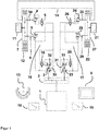
- FIG. 1 shows a schematic diagram of the drive diagram for a drive system for tracked vehicles with two hydraulic pumps and two hydraulic motors each for a right and a left hydraulic circuit:
- a drive motor 1 drives hydraulic circuits 16, 17 which can be controlled independently of one another via a pump distributor gear 2.
- the hydraulic circuit 16 consists of hydraulic pumps designed as hydraulic traction pumps 3.32 and hydraulic motors designed as hydraulic traction motors 4.5.
- the hydraulic circuit 17 consists analogously of hydraulic pumps designed as hydraulic travel pumps 23, 33 and hydraulic motors designed as hydraulic travel motors 24, 25.
- the hydraulic traction motors 4.5 and 24.25 work independently of each other on a summation gear 7.27.
- the outputs of the summation gears 7, 27 drive the tracked vehicle directly via chains 12, 22 or optionally via further gears 11 on the left and gears 21 on the right.
- the hydraulic circuits 16, 17 are set on both sides and quantitatively by a control and regulating unit 8 in such a way that the translation of the hydraulic circuits 16, 17 are the same and therefore the output speeds of the summation gears 7, 27 are the same.
- the output speeds of the hydraulic motors 5.25 are measured as actual values via a speed sensor 9 (left) and a speed sensor 29 (right) and fed to the control and regulating unit 8, which controls the independently controllable hydraulic circuits 16, 17 to ensure that they are the same speed.
- the actual values of the output speeds can optionally also be recorded via speed sensors (not shown) in the summation gears 7.27 or gears 11.21 (left, right).
- the hydraulic circuits 16, 17 are set quantitatively by the control and regulating unit 8 to unequal ratios of the hydraulic circuits 16, 17, depending on reference variables which are measured on the steering wheel 13 and which are supplied to the control and regulating unit 8.
- One of the two hydraulic circuits 16, 17 acts as a brake during cornering.
- the hydraulic circuit 17 is set to lower speed values than the hydraulic circuit 16, as a result of which the hydraulic motors 24, 25 then act as a brake, i.e. in pump operation, driven by the vehicle mass, and the hydraulic pumps 23, 33 operate in a motorized manner and in turn drive now also the pump transfer case 2.
- the recuperated power or energy directed into the pump transfer case 2 can now be reused, for example for operating auxiliary drives (not shown) or as additional mileage for the hydraulic circuit 16.
- the hydraulic circuit 16 in this operating case must be able to transmit the entire driving and steering power alone while the braking hydraulic circuit 17 usually only has to transmit relatively low power values.
- the right hand drive causes the drive pump 33 to be switched off due to the low power requirement, so that only the drive pump 23 is active in the hydraulic circuit 17.
- the hydraulic circuit 16 when the driving power is high, no pump shutdown is activated, but both hydraulic pumps 3/32 transmit power.
- Figure 2 shows a schematic diagram of the drive scheme for a drive system for tracked vehicles with a hydraulically switched off hydraulic pump with right-hand drive.
- the hydraulic pumps 33 can be switched off mechanically by releasing the pump coupling 31 and / or hydraulically by means of the pump shut-off valve 20.
- Figure 3 shows a schematic diagram of the drive scheme for a drive system for tracked vehicles with a hydraulically switched off hydraulic pump and a hydraulically switched off hydraulic traction motor in right-hand drive at high speed.
- the hydraulic pump 33 is switched off and the hydraulic motor 24 is switched off via the pump shut-off valve 20 and / or via the engine shut-off valve 26.
- the hydraulic traction motor 24 is switched off as a function of the currently required values for power, traction and speed.
- ⁇ b> reference number ⁇ /b> 1 Drive motor 27 Summation gear on the right 2nd Pump transfer case 28 free 3rd first hydraulic pump on the left 29
- Right speed sensor 4th first hydraulic drive motor on the left 30th Pump coupling on the left 5 second hydraulic drive motor on the left 31
- Pump coupling on the right 6 Engine shut-off valve on the left 32 second hydraulic pump on the left 7 Summation gear on the left 33 second hydraulic pump on the right 8th
- Motor coupling on the right 10th Pump shut-off valve on the left 11 Gearbox left 12th Chain left 13 steering wheel 14
- Vehicle mass 15 free 16 Hydraulic circuit on the left 17th Hydraulic circuit on the right 18th accelerator 19th brake 20th Pump shut-off valve on the right 21
- Right gearbox 22 22 Chain right 23 first hydraulic pump on the right 24th first hydraulic drive motor on the right 25th second hydraulic drive motor on the
Landscapes
- Engineering & Computer Science (AREA)
- Chemical & Material Sciences (AREA)
- Combustion & Propulsion (AREA)
- Transportation (AREA)
- Mechanical Engineering (AREA)
- Motor Power Transmission Devices (AREA)
- Control Of Fluid Gearings (AREA)
Claims (16)
- Système d'entraînement pour des véhicules à chenilles et des machines de travail à chenilles, composé d'au moins un moteur d'entraînement (1), d'au moins une boîte de transfert à pompes (2), qui est en liaison opérationnelle avec le moteur d'entraînement (1), et d'au moins un circuit hydraulique (16, 17) réglable en continu de chaque côté du véhicule, caractérisé en ce que chaque circuit hydraulique (16, 17) est constitué d'au moins deux pompes hydrauliques (3, 32, 23, 33) et d'au moins un moteur hydraulique (5, 25), les pompes hydrauliques (3, 32, 23, 33) étant en liaison opérationnelle avec la boîte de transfert à pompes (2), au moins un moteur hydraulique (4, 24) et/ou au moins une pompe hydraulique (32, 33) pouvant être activé ou désactivé pour améliorer les niveaux d'efficacité.
- Système d'entraînement selon la revendication 1, caractérisé en ce que la désactivation des moteurs hydrauliques (4, 24) et/ou des pompes hydrauliques (32, 33) se fait mécaniquement via des accouplements (30, 31, 34, 35) et/ou hydrauliquement via des vannes d'arrêt (10, 20, 34, 35).
- Système d'entraînement selon la revendication 1 ou la revendication 2, caractérisé en ce que la désactivation des pompes hydrauliques (32, 33) est réalisée en fonction du rendement.
- Système d'entraînement selon l'une des revendications 1 à 3, caractérisé en ce que la désactivation des pompes (32, 33) est réalisée en fonction de la pression.
- Système d'entraînement selon l'une des revendications 1 à 4, caractérisé en ce que la désactivation des moteurs hydrauliques configurés comme des moteurs de traction hydrauliques (4, 24) est réalisée en fonction de la force de traction et/ou en fonction de la vitesse du moteur.
- Système d'entraînement selon l'une des revendications 1 à 5, caractérisé en ce que les vannes d'arrêt (6, 10, 20, 26) sont configurées comme des soupapes directionnelles continues ou discontinues.
- Système d'entraînement selon l'une des revendications 1 à 6, caractérisé en ce que chaque circuit hydraulique (16, 17) est en liaison opérationnelle avec au moins un mécanisme de sommation (7, 27).
- Système d'entraînement selon l'une des revendications 1 à 7, caractérisé en ce que la boîte de transfert à pompes (2), les circuits hydrauliques (16, 17) et les mécanismes de sommation (7, 27) sont logés dans un boîtier.
- Système d'entraînement selon l'une des revendications 1 à 8, caractérisé en ce que la direction et le niveau d'un flux de rendement ou des deux flux de rendement des circuits hydrauliques (16, 17) est/sont réglé(s) de sorte qu'un mouvement de direction contrôlé d'une masse de véhicule (14) est obtenu.
- Système d'entraînement selon l'une des revendications 1 à 9, caractérisé en ce que pour régler un mouvement de direction contrôlé du véhicule moteur ou de la machine de travail, l'angle de rotation d'un volant (13) est saisi de manière métrologique et peut être utilisé en tant que variable de référence.
- Système d'entraînement selon l'une des revendications 1 à 10, caractérisé en ce que dans le cas où au moins un moteur hydraulique (4, 24) supplémentaire et pouvant être désactivé est utilisé par côté de véhicule, le réglage du niveau d'un rendement à récupérer peut être réalisé sélectivement par au moins un moteur hydraulique (4, 24) et/ou par au moins un moteur hydraulique (5, 25).
- Système d'entraînement selon l'une des revendications 1 à 11, caractérisé en ce que dans le cas où au moins un moteur hydraulique (4, 24) supplémentaire et pouvant être désactivé est utilisé par côté de véhicule, la zone de la liaison directe entre des raccords à haute pression (A, B) des moteurs hydrauliques (5, 25), qui ne peuvent pas être désactivés, et des raccords à haute pression (C, D) des pompes hydrauliques (3, 23) peut être réalisée en forme de soupapes sans utiliser des résistances hydrauliques.
- Procédé de commande d'un système d'entraînement pour des véhicules à chenilles et des machines de travail à chenilles selon l'une des revendications 1 à 12, caractérisé en ce que pour améliorer les niveaux d'efficacité, la direction et le niveau des flux de rendement des circuits hydrauliques (16, 17) peuvent être réglés en continu et de manière indépendante l'un de l'autre, de sorte que la position de l'accélérateur est saisie en tant que variable de référence par l'unité de commande (8) et ils sont comparés avec les vitesses de rotation des moteurs de traction hydrauliques (5, 25) en tant que valeurs réelles, et en fonction de cela l'ajustement des pompes hydrauliques (3, 23, 32, 33) et l'ajustement des moteurs de traction hydrauliques (4, 5, 24, 25) sont réalisés et les pompes hydrauliques (32, 33) et les moteurs de traction hydrauliques (4, 24) sont connectés et désactivés.
- Procédé selon la revendication 13, caractérisé en ce que l'angle de braquage fixé par le conducteur est saisi de manière métrologique en tant que variable de référence et les vitesses de rotation des arbres entraînés sont saisies directement ou indirectement de manière métrologique en tant que valeurs réelles par des capteurs de vitesse de rotation (9, 29), toutes les valeurs mesurées étant transmises à une unité de commande (8) électronique, qui commande la direction de manière correspondante à la variable de référence fixée par le conducteur par moyen d'ajustements différents des circuits hydrauliques (16, 17).
- Procédé selon l'une des revendications 13 à 14, caractérisé en ce que pour optimiser le comportement de roulement et de braquage et les niveaux d'efficacité, le réglage des moteurs de traction hydrauliques (4, 5, 24, 25), des pompes hydrauliques (3, 32, 23, 33) et de la vitesse de rotation du moteur d'entraînement (1) est effectué par moyen d'une commande adaptative par rapport aux paramètres.
- Procédé selon l'une des revendications 13 à 15, caractérisé en ce que les paramètres utilisés pour une commande adaptative par rapport aux paramètres, à savoir les données opérationnelles du moteur d'entraînement, les pressions hydrauliques, les températures et les vitesses de rotation des composants d'entraînement individuels ou de tous les composants d'entraînement ainsi que les valeurs de réglage du personnel de conduite, de l'accélérateur, du frein et du volant sont complètement ou partiellement utilisées.
Priority Applications (1)
| Application Number | Priority Date | Filing Date | Title |
|---|---|---|---|
| EP17161794.7A EP3378736B1 (fr) | 2017-03-20 | 2017-03-20 | Système d'entraînement pour véhicules à chenilles et engins de travail à chenilles et procédé de commande d'un système d'entraînement pour véhicules à chenilles et engins de travail à chenilles |
Applications Claiming Priority (1)
| Application Number | Priority Date | Filing Date | Title |
|---|---|---|---|
| EP17161794.7A EP3378736B1 (fr) | 2017-03-20 | 2017-03-20 | Système d'entraînement pour véhicules à chenilles et engins de travail à chenilles et procédé de commande d'un système d'entraînement pour véhicules à chenilles et engins de travail à chenilles |
Publications (2)
| Publication Number | Publication Date |
|---|---|
| EP3378736A1 EP3378736A1 (fr) | 2018-09-26 |
| EP3378736B1 true EP3378736B1 (fr) | 2020-04-29 |
Family
ID=58398043
Family Applications (1)
| Application Number | Title | Priority Date | Filing Date |
|---|---|---|---|
| EP17161794.7A Active EP3378736B1 (fr) | 2017-03-20 | 2017-03-20 | Système d'entraînement pour véhicules à chenilles et engins de travail à chenilles et procédé de commande d'un système d'entraînement pour véhicules à chenilles et engins de travail à chenilles |
Country Status (1)
| Country | Link |
|---|---|
| EP (1) | EP3378736B1 (fr) |
Families Citing this family (1)
| Publication number | Priority date | Publication date | Assignee | Title |
|---|---|---|---|---|
| DE102020201473A1 (de) * | 2020-02-06 | 2021-08-12 | Zf Friedrichshafen Ag | Lenkschaltgetriebe für Kettenfahrzeuge als Parallelhybrid |
Family Cites Families (5)
| Publication number | Priority date | Publication date | Assignee | Title |
|---|---|---|---|---|
| FR2464869A1 (fr) * | 1979-09-10 | 1981-03-20 | France Etat | Groupe propulseur a transmissions hydrostatiques assurant la translation et la direction avec recyclage hydraulique de puissance en virage |
| ATE32445T1 (de) * | 1984-02-09 | 1988-02-15 | Moog Gmbh | Steuerschaltung, insbesondere fuer ein kettenfahrzeug. |
| US5282516A (en) | 1992-06-01 | 1994-02-01 | Caterpillar Inc. | Regenerative steering system for hydrostatic drives |
| JP2776703B2 (ja) | 1992-10-09 | 1998-07-16 | 新キャタピラー三菱株式会社 | 建設機械の油圧回路 |
| DE19833942C2 (de) * | 1998-07-28 | 2000-06-08 | Brueninghaus Hydromatik Gmbh | Hydrostatischer Fahrantrieb mit Differentialsperre |
-
2017
- 2017-03-20 EP EP17161794.7A patent/EP3378736B1/fr active Active
Non-Patent Citations (1)
| Title |
|---|
| None * |
Also Published As
| Publication number | Publication date |
|---|---|
| EP3378736A1 (fr) | 2018-09-26 |
Similar Documents
| Publication | Publication Date | Title |
|---|---|---|
| EP3006245B1 (fr) | Procede de commande de transmission | |
| EP2296926B1 (fr) | Dispositif de commande pour véhicules à entraînement hydrostatique auxiliaire | |
| DE3145218A1 (de) | Antriebssystem und steuerung fuer verstellmotor(en) | |
| EP3080473B1 (fr) | Système hydraulique pour double embrayage ainsi que procédé de commande ou de refroidissement du double embrayage | |
| DE2500627A1 (de) | Zugmaschine mit gewichtsuebertragungseinrichtung zwischen der kupplung und den schienenraedern | |
| EP3083314B1 (fr) | Unité différentielle d'un véhicule automobile et son procédé de commande | |
| EP1828643B1 (fr) | Procede pour freiner un vehicule entraine au moyen d'une boite de vitesses hydrostatique et boite de vitesses hydrostatique | |
| EP3354504B1 (fr) | Système d'entrainement du groupe motopropulseur | |
| DE112004000130T5 (de) | Stufenlos veränderbares Getriebe | |
| DE102006061516A1 (de) | Hydraulikanordnung zur Ansteuerung zweier Aktuatoren | |
| DE102004046177A1 (de) | Fahrzeugsteuerungssystem | |
| EP2068045A2 (fr) | Système d'entraînement d'un véhicule de travail | |
| DE102006009064A1 (de) | Verfahren sowie Vorrichtung zur Regelung eines Antriebssystems | |
| EP3378736B1 (fr) | Système d'entraînement pour véhicules à chenilles et engins de travail à chenilles et procédé de commande d'un système d'entraînement pour véhicules à chenilles et engins de travail à chenilles | |
| EP1561054B1 (fr) | Commande pour un groupe propulseur hydrostatique | |
| DE102019120973A1 (de) | Hydrostatischer Fahrantrieb einer allradgetriebenen Arbeitsmaschine | |
| DE102011055173B4 (de) | Antriebsstrang mit einem hydrostatischen Getriebe zum Antrieb eines Schaltgetriebes | |
| DE112007002436B4 (de) | Hydrostatische Getriebevorrichtung einer Maschine | |
| DE102015012929A1 (de) | Antriebssystem für Kettenfahrzeuge und mobile Arbeitsmaschinen sowie Verfahren zur Steuerung für Kettenfahrzeuge und mobile Arbeitsmaschinen | |
| DE102011055177B4 (de) | Hydrostatischer Fahrantrieb für eine allradgetriebene Arbeitsmaschine | |
| DE2537229C3 (de) | Lenkstuerungsvorrichtung für Gleiskettenfahrzeuge | |
| DE102011055174B4 (de) | Verfahren zum Schalten eines zwischen mindestens zwei Übersetzungsstufen schaltbaren Schaltgetriebes eines Fahrantriebs | |
| EP1185807A1 (fr) | Systeme d'entrainement hydrostatique | |
| AT524327B1 (de) | Verfahren zum Steuern eines elektrifizierten Lenk- und Antriebssystems | |
| DE102016111962A1 (de) | Antriebssystem für Kettenfahrzeuge und mobile Arbeitsmaschinen zur Regeneration von kinetischer Energie sowie Verfahren zur Steuerung der Regeneration von kinetischer Energie für Kettenfahrzeuge und mobile Arbeitsmaschinen |
Legal Events
| Date | Code | Title | Description |
|---|---|---|---|
| PUAI | Public reference made under article 153(3) epc to a published international application that has entered the european phase |
Free format text: ORIGINAL CODE: 0009012 |
|
| STAA | Information on the status of an ep patent application or granted ep patent |
Free format text: STATUS: THE APPLICATION HAS BEEN PUBLISHED |
|
| AK | Designated contracting states |
Kind code of ref document: A1 Designated state(s): AL AT BE BG CH CY CZ DE DK EE ES FI FR GB GR HR HU IE IS IT LI LT LU LV MC MK MT NL NO PL PT RO RS SE SI SK SM TR |
|
| AX | Request for extension of the european patent |
Extension state: BA ME |
|
| STAA | Information on the status of an ep patent application or granted ep patent |
Free format text: STATUS: REQUEST FOR EXAMINATION WAS MADE |
|
| 17P | Request for examination filed |
Effective date: 20190219 |
|
| RBV | Designated contracting states (corrected) |
Designated state(s): AL AT BE BG CH CY CZ DE DK EE ES FI FR GB GR HR HU IE IS IT LI LT LU LV MC MK MT NL NO PL PT RO RS SE SI SK SM TR |
|
| GRAP | Despatch of communication of intention to grant a patent |
Free format text: ORIGINAL CODE: EPIDOSNIGR1 |
|
| STAA | Information on the status of an ep patent application or granted ep patent |
Free format text: STATUS: GRANT OF PATENT IS INTENDED |
|
| INTG | Intention to grant announced |
Effective date: 20191022 |
|
| GRAS | Grant fee paid |
Free format text: ORIGINAL CODE: EPIDOSNIGR3 |
|
| GRAA | (expected) grant |
Free format text: ORIGINAL CODE: 0009210 |
|
| STAA | Information on the status of an ep patent application or granted ep patent |
Free format text: STATUS: THE PATENT HAS BEEN GRANTED |
|
| AK | Designated contracting states |
Kind code of ref document: B1 Designated state(s): AL AT BE BG CH CY CZ DE DK EE ES FI FR GB GR HR HU IE IS IT LI LT LU LV MC MK MT NL NO PL PT RO RS SE SI SK SM TR |
|
| REG | Reference to a national code |
Ref country code: GB Ref legal event code: FG4D Free format text: NOT ENGLISH |
|
| REG | Reference to a national code |
Ref country code: CH Ref legal event code: EP |
|
| REG | Reference to a national code |
Ref country code: AT Ref legal event code: REF Ref document number: 1262885 Country of ref document: AT Kind code of ref document: T Effective date: 20200515 |
|
| REG | Reference to a national code |
Ref country code: DE Ref legal event code: R096 Ref document number: 502017004933 Country of ref document: DE |
|
| REG | Reference to a national code |
Ref country code: IE Ref legal event code: FG4D Free format text: LANGUAGE OF EP DOCUMENT: GERMAN |
|
| REG | Reference to a national code |
Ref country code: FI Ref legal event code: FGE |
|
| REG | Reference to a national code |
Ref country code: SE Ref legal event code: TRGR |
|
| REG | Reference to a national code |
Ref country code: NL Ref legal event code: MP Effective date: 20200429 |
|
| REG | Reference to a national code |
Ref country code: LT Ref legal event code: MG4D |
|
| PG25 | Lapsed in a contracting state [announced via postgrant information from national office to epo] |
Ref country code: LT Free format text: LAPSE BECAUSE OF FAILURE TO SUBMIT A TRANSLATION OF THE DESCRIPTION OR TO PAY THE FEE WITHIN THE PRESCRIBED TIME-LIMIT Effective date: 20200429 Ref country code: GR Free format text: LAPSE BECAUSE OF FAILURE TO SUBMIT A TRANSLATION OF THE DESCRIPTION OR TO PAY THE FEE WITHIN THE PRESCRIBED TIME-LIMIT Effective date: 20200730 Ref country code: PT Free format text: LAPSE BECAUSE OF FAILURE TO SUBMIT A TRANSLATION OF THE DESCRIPTION OR TO PAY THE FEE WITHIN THE PRESCRIBED TIME-LIMIT Effective date: 20200831 Ref country code: IS Free format text: LAPSE BECAUSE OF FAILURE TO SUBMIT A TRANSLATION OF THE DESCRIPTION OR TO PAY THE FEE WITHIN THE PRESCRIBED TIME-LIMIT Effective date: 20200829 Ref country code: NO Free format text: LAPSE BECAUSE OF FAILURE TO SUBMIT A TRANSLATION OF THE DESCRIPTION OR TO PAY THE FEE WITHIN THE PRESCRIBED TIME-LIMIT Effective date: 20200729 |
|
| PG25 | Lapsed in a contracting state [announced via postgrant information from national office to epo] |
Ref country code: BG Free format text: LAPSE BECAUSE OF FAILURE TO SUBMIT A TRANSLATION OF THE DESCRIPTION OR TO PAY THE FEE WITHIN THE PRESCRIBED TIME-LIMIT Effective date: 20200729 Ref country code: HR Free format text: LAPSE BECAUSE OF FAILURE TO SUBMIT A TRANSLATION OF THE DESCRIPTION OR TO PAY THE FEE WITHIN THE PRESCRIBED TIME-LIMIT Effective date: 20200429 Ref country code: RS Free format text: LAPSE BECAUSE OF FAILURE TO SUBMIT A TRANSLATION OF THE DESCRIPTION OR TO PAY THE FEE WITHIN THE PRESCRIBED TIME-LIMIT Effective date: 20200429 Ref country code: LV Free format text: LAPSE BECAUSE OF FAILURE TO SUBMIT A TRANSLATION OF THE DESCRIPTION OR TO PAY THE FEE WITHIN THE PRESCRIBED TIME-LIMIT Effective date: 20200429 |
|
| PG25 | Lapsed in a contracting state [announced via postgrant information from national office to epo] |
Ref country code: AL Free format text: LAPSE BECAUSE OF FAILURE TO SUBMIT A TRANSLATION OF THE DESCRIPTION OR TO PAY THE FEE WITHIN THE PRESCRIBED TIME-LIMIT Effective date: 20200429 Ref country code: NL Free format text: LAPSE BECAUSE OF FAILURE TO SUBMIT A TRANSLATION OF THE DESCRIPTION OR TO PAY THE FEE WITHIN THE PRESCRIBED TIME-LIMIT Effective date: 20200429 |
|
| PG25 | Lapsed in a contracting state [announced via postgrant information from national office to epo] |
Ref country code: ES Free format text: LAPSE BECAUSE OF FAILURE TO SUBMIT A TRANSLATION OF THE DESCRIPTION OR TO PAY THE FEE WITHIN THE PRESCRIBED TIME-LIMIT Effective date: 20200429 Ref country code: RO Free format text: LAPSE BECAUSE OF FAILURE TO SUBMIT A TRANSLATION OF THE DESCRIPTION OR TO PAY THE FEE WITHIN THE PRESCRIBED TIME-LIMIT Effective date: 20200429 Ref country code: CZ Free format text: LAPSE BECAUSE OF FAILURE TO SUBMIT A TRANSLATION OF THE DESCRIPTION OR TO PAY THE FEE WITHIN THE PRESCRIBED TIME-LIMIT Effective date: 20200429 Ref country code: EE Free format text: LAPSE BECAUSE OF FAILURE TO SUBMIT A TRANSLATION OF THE DESCRIPTION OR TO PAY THE FEE WITHIN THE PRESCRIBED TIME-LIMIT Effective date: 20200429 Ref country code: SM Free format text: LAPSE BECAUSE OF FAILURE TO SUBMIT A TRANSLATION OF THE DESCRIPTION OR TO PAY THE FEE WITHIN THE PRESCRIBED TIME-LIMIT Effective date: 20200429 Ref country code: DK Free format text: LAPSE BECAUSE OF FAILURE TO SUBMIT A TRANSLATION OF THE DESCRIPTION OR TO PAY THE FEE WITHIN THE PRESCRIBED TIME-LIMIT Effective date: 20200429 |
|
| REG | Reference to a national code |
Ref country code: DE Ref legal event code: R097 Ref document number: 502017004933 Country of ref document: DE |
|
| PG25 | Lapsed in a contracting state [announced via postgrant information from national office to epo] |
Ref country code: SK Free format text: LAPSE BECAUSE OF FAILURE TO SUBMIT A TRANSLATION OF THE DESCRIPTION OR TO PAY THE FEE WITHIN THE PRESCRIBED TIME-LIMIT Effective date: 20200429 Ref country code: PL Free format text: LAPSE BECAUSE OF FAILURE TO SUBMIT A TRANSLATION OF THE DESCRIPTION OR TO PAY THE FEE WITHIN THE PRESCRIBED TIME-LIMIT Effective date: 20200429 |
|
| PLBE | No opposition filed within time limit |
Free format text: ORIGINAL CODE: 0009261 |
|
| STAA | Information on the status of an ep patent application or granted ep patent |
Free format text: STATUS: NO OPPOSITION FILED WITHIN TIME LIMIT |
|
| 26N | No opposition filed |
Effective date: 20210201 |
|
| PGFP | Annual fee paid to national office [announced via postgrant information from national office to epo] |
Ref country code: FR Payment date: 20210324 Year of fee payment: 5 Ref country code: IT Payment date: 20210329 Year of fee payment: 5 Ref country code: FI Payment date: 20210322 Year of fee payment: 5 |
|
| PG25 | Lapsed in a contracting state [announced via postgrant information from national office to epo] |
Ref country code: SI Free format text: LAPSE BECAUSE OF FAILURE TO SUBMIT A TRANSLATION OF THE DESCRIPTION OR TO PAY THE FEE WITHIN THE PRESCRIBED TIME-LIMIT Effective date: 20200429 |
|
| PGFP | Annual fee paid to national office [announced via postgrant information from national office to epo] |
Ref country code: TR Payment date: 20210318 Year of fee payment: 5 Ref country code: SE Payment date: 20210319 Year of fee payment: 5 Ref country code: GB Payment date: 20210324 Year of fee payment: 5 Ref country code: DE Payment date: 20210319 Year of fee payment: 5 |
|
| PG25 | Lapsed in a contracting state [announced via postgrant information from national office to epo] |
Ref country code: MC Free format text: LAPSE BECAUSE OF FAILURE TO SUBMIT A TRANSLATION OF THE DESCRIPTION OR TO PAY THE FEE WITHIN THE PRESCRIBED TIME-LIMIT Effective date: 20200429 |
|
| REG | Reference to a national code |
Ref country code: CH Ref legal event code: PL |
|
| REG | Reference to a national code |
Ref country code: BE Ref legal event code: MM Effective date: 20210331 |
|
| PG25 | Lapsed in a contracting state [announced via postgrant information from national office to epo] |
Ref country code: LU Free format text: LAPSE BECAUSE OF NON-PAYMENT OF DUE FEES Effective date: 20210320 Ref country code: LI Free format text: LAPSE BECAUSE OF NON-PAYMENT OF DUE FEES Effective date: 20210331 Ref country code: CH Free format text: LAPSE BECAUSE OF NON-PAYMENT OF DUE FEES Effective date: 20210331 Ref country code: IE Free format text: LAPSE BECAUSE OF NON-PAYMENT OF DUE FEES Effective date: 20210320 |
|
| PG25 | Lapsed in a contracting state [announced via postgrant information from national office to epo] |
Ref country code: BE Free format text: LAPSE BECAUSE OF NON-PAYMENT OF DUE FEES Effective date: 20210331 |
|
| REG | Reference to a national code |
Ref country code: DE Ref legal event code: R119 Ref document number: 502017004933 Country of ref document: DE |
|
| REG | Reference to a national code |
Ref country code: FI Ref legal event code: MAE |
|
| PG25 | Lapsed in a contracting state [announced via postgrant information from national office to epo] |
Ref country code: FI Free format text: LAPSE BECAUSE OF NON-PAYMENT OF DUE FEES Effective date: 20220320 |
|
| GBPC | Gb: european patent ceased through non-payment of renewal fee |
Effective date: 20220320 |
|
| PG25 | Lapsed in a contracting state [announced via postgrant information from national office to epo] |
Ref country code: SE Free format text: LAPSE BECAUSE OF NON-PAYMENT OF DUE FEES Effective date: 20220321 Ref country code: GB Free format text: LAPSE BECAUSE OF NON-PAYMENT OF DUE FEES Effective date: 20220320 Ref country code: FR Free format text: LAPSE BECAUSE OF NON-PAYMENT OF DUE FEES Effective date: 20220331 Ref country code: DE Free format text: LAPSE BECAUSE OF NON-PAYMENT OF DUE FEES Effective date: 20221001 |
|
| REG | Reference to a national code |
Ref country code: AT Ref legal event code: MM01 Ref document number: 1262885 Country of ref document: AT Kind code of ref document: T Effective date: 20220320 |
|
| PG25 | Lapsed in a contracting state [announced via postgrant information from national office to epo] |
Ref country code: IT Free format text: LAPSE BECAUSE OF NON-PAYMENT OF DUE FEES Effective date: 20220320 |
|
| PG25 | Lapsed in a contracting state [announced via postgrant information from national office to epo] |
Ref country code: CY Free format text: LAPSE BECAUSE OF FAILURE TO SUBMIT A TRANSLATION OF THE DESCRIPTION OR TO PAY THE FEE WITHIN THE PRESCRIBED TIME-LIMIT Effective date: 20200429 |
|
| PG25 | Lapsed in a contracting state [announced via postgrant information from national office to epo] |
Ref country code: HU Free format text: LAPSE BECAUSE OF FAILURE TO SUBMIT A TRANSLATION OF THE DESCRIPTION OR TO PAY THE FEE WITHIN THE PRESCRIBED TIME-LIMIT; INVALID AB INITIO Effective date: 20170320 Ref country code: AT Free format text: LAPSE BECAUSE OF NON-PAYMENT OF DUE FEES Effective date: 20220320 |
|
| PG25 | Lapsed in a contracting state [announced via postgrant information from national office to epo] |
Ref country code: MK Free format text: LAPSE BECAUSE OF FAILURE TO SUBMIT A TRANSLATION OF THE DESCRIPTION OR TO PAY THE FEE WITHIN THE PRESCRIBED TIME-LIMIT Effective date: 20200429 |