EP3081872B1 - Haushaltsgerät - Google Patents
Haushaltsgerät Download PDFInfo
- Publication number
- EP3081872B1 EP3081872B1 EP16159876.8A EP16159876A EP3081872B1 EP 3081872 B1 EP3081872 B1 EP 3081872B1 EP 16159876 A EP16159876 A EP 16159876A EP 3081872 B1 EP3081872 B1 EP 3081872B1
- Authority
- EP
- European Patent Office
- Prior art keywords
- water
- open
- close
- air inflow
- water tank
- Prior art date
- Legal status (The legal status is an assumption and is not a legal conclusion. Google has not performed a legal analysis and makes no representation as to the accuracy of the status listed.)
- Active
Links
- XLYOFNOQVPJJNP-UHFFFAOYSA-N water Substances O XLYOFNOQVPJJNP-UHFFFAOYSA-N 0.000 claims description 420
- 230000007423 decrease Effects 0.000 claims description 4
- 239000008400 supply water Substances 0.000 claims description 2
- 238000000034 method Methods 0.000 description 11
- 230000008569 process Effects 0.000 description 11
- 239000000463 material Substances 0.000 description 9
- 238000000926 separation method Methods 0.000 description 6
- 238000001704 evaporation Methods 0.000 description 3
- 239000013013 elastic material Substances 0.000 description 2
- 238000012986 modification Methods 0.000 description 2
- 230000004048 modification Effects 0.000 description 2
- 239000004033 plastic Substances 0.000 description 2
- 238000002604 ultrasonography Methods 0.000 description 2
- 230000003213 activating effect Effects 0.000 description 1
- 238000004887 air purification Methods 0.000 description 1
- 238000004891 communication Methods 0.000 description 1
- 239000000470 constituent Substances 0.000 description 1
- 230000007812 deficiency Effects 0.000 description 1
- 238000004332 deodorization Methods 0.000 description 1
- 238000006073 displacement reaction Methods 0.000 description 1
- 239000000428 dust Substances 0.000 description 1
- 230000008020 evaporation Effects 0.000 description 1
- 238000010438 heat treatment Methods 0.000 description 1
- 230000006872 improvement Effects 0.000 description 1
- 230000010354 integration Effects 0.000 description 1
- 230000007257 malfunction Effects 0.000 description 1
- 238000004519 manufacturing process Methods 0.000 description 1
- 230000007246 mechanism Effects 0.000 description 1
- 230000000149 penetrating effect Effects 0.000 description 1
- 230000000241 respiratory effect Effects 0.000 description 1
- 239000007921 spray Substances 0.000 description 1
- 238000013022 venting Methods 0.000 description 1
Images


Classifications
-
- F—MECHANICAL ENGINEERING; LIGHTING; HEATING; WEAPONS; BLASTING
- F24—HEATING; RANGES; VENTILATING
- F24F—AIR-CONDITIONING; AIR-HUMIDIFICATION; VENTILATION; USE OF AIR CURRENTS FOR SCREENING
- F24F6/00—Air-humidification, e.g. cooling by humidification
- F24F6/02—Air-humidification, e.g. cooling by humidification by evaporation of water in the air
-
- F—MECHANICAL ENGINEERING; LIGHTING; HEATING; WEAPONS; BLASTING
- F24—HEATING; RANGES; VENTILATING
- F24F—AIR-CONDITIONING; AIR-HUMIDIFICATION; VENTILATION; USE OF AIR CURRENTS FOR SCREENING
- F24F6/00—Air-humidification, e.g. cooling by humidification
-
- F—MECHANICAL ENGINEERING; LIGHTING; HEATING; WEAPONS; BLASTING
- F24—HEATING; RANGES; VENTILATING
- F24F—AIR-CONDITIONING; AIR-HUMIDIFICATION; VENTILATION; USE OF AIR CURRENTS FOR SCREENING
- F24F11/00—Control or safety arrangements
- F24F11/70—Control systems characterised by their outputs; Constructional details thereof
- F24F11/72—Control systems characterised by their outputs; Constructional details thereof for controlling the supply of treated air, e.g. its pressure
- F24F11/74—Control systems characterised by their outputs; Constructional details thereof for controlling the supply of treated air, e.g. its pressure for controlling air flow rate or air velocity
-
- F—MECHANICAL ENGINEERING; LIGHTING; HEATING; WEAPONS; BLASTING
- F24—HEATING; RANGES; VENTILATING
- F24F—AIR-CONDITIONING; AIR-HUMIDIFICATION; VENTILATION; USE OF AIR CURRENTS FOR SCREENING
- F24F13/00—Details common to, or for air-conditioning, air-humidification, ventilation or use of air currents for screening
- F24F13/24—Means for preventing or suppressing noise
-
- F—MECHANICAL ENGINEERING; LIGHTING; HEATING; WEAPONS; BLASTING
- F24—HEATING; RANGES; VENTILATING
- F24F—AIR-CONDITIONING; AIR-HUMIDIFICATION; VENTILATION; USE OF AIR CURRENTS FOR SCREENING
- F24F6/00—Air-humidification, e.g. cooling by humidification
- F24F6/12—Air-humidification, e.g. cooling by humidification by forming water dispersions in the air
- F24F6/16—Air-humidification, e.g. cooling by humidification by forming water dispersions in the air using rotating elements
-
- A—HUMAN NECESSITIES
- A61—MEDICAL OR VETERINARY SCIENCE; HYGIENE
- A61M—DEVICES FOR INTRODUCING MEDIA INTO, OR ONTO, THE BODY; DEVICES FOR TRANSDUCING BODY MEDIA OR FOR TAKING MEDIA FROM THE BODY; DEVICES FOR PRODUCING OR ENDING SLEEP OR STUPOR
- A61M16/00—Devices for influencing the respiratory system of patients by gas treatment, e.g. mouth-to-mouth respiration; Tracheal tubes
- A61M16/10—Preparation of respiratory gases or vapours
- A61M16/14—Preparation of respiratory gases or vapours by mixing different fluids, one of them being in a liquid phase
- A61M16/16—Devices to humidify the respiration air
- A61M16/162—Water-reservoir filling system, e.g. automatic
- A61M16/164—Water-reservoir filling system, e.g. automatic including a liquid inlet valve system
- A61M16/165—Water-reservoir filling system, e.g. automatic including a liquid inlet valve system with a float actuator
- A61M16/167—Water-reservoir filling system, e.g. automatic including a liquid inlet valve system with a float actuator acting vertically on the valve
-
- F—MECHANICAL ENGINEERING; LIGHTING; HEATING; WEAPONS; BLASTING
- F24—HEATING; RANGES; VENTILATING
- F24F—AIR-CONDITIONING; AIR-HUMIDIFICATION; VENTILATION; USE OF AIR CURRENTS FOR SCREENING
- F24F6/00—Air-humidification, e.g. cooling by humidification
- F24F2006/008—Air-humidifier with water reservoir
Definitions
- the present disclosure relates to a humidifier and home appliance having a structure to prevent noise from being produced from a water tank during replenishment of water to a water reservoir.
- Humidifiers are generally used to keep indoor humidity at an optimum level and prevent many respiratory problems.
- the humidifier sprays water stored in the water reservoir in the form of droplets, or evaporates the water.
- the humidifier is replenished with water from a water tank when the water level of the water reservoir drops below a certain level, and this makes unusual noise due to air bubbles going into the water tank.
- JP 2010-169933 A discloses a water supply device including a water tank, a cap provided at an opening on one end side of the water tank, a stopcock valve for closing a water outflow port provided in the cap, a water receiving part for storing a predetermined amount of water flowed out via the water outflow port and then supplying the water to a required portion, and a stopcock valve opening member provided in the position corresponding to the water outflow port of the water receiving part and inserted into the water outflow port to open the stopcock valve when the water tank is installed in the water receiving part.
- the stopcock valve has a flap structure enabling vertical rotation around one end side to open/close the inlet side of the water outflow port of the cap. This enables secure water supply.
- JP 3110210 U discloses a humidifier including a water supply tank detachably attached to a main body and dripping water into a water tank, a water supply tank for controlling the dripping of water from the dropping port to supply water to the water tank, and a water level control means for maintaining the water level in the water supply tank at a constant level, wherein the water supply tank has a water supply port penetrating the outside with a fresh air, and the water level control means is provided at the dropping port.
- the humidifier further comprises a float part having a floating part at one end pivotally supporting the central part and a push rod at the other end, and a float seesawing in conjunction with the displacement of the water level in the aquarium, wherein the pushing rod faces the lower end face of the valve stem extending from the valve body, and in conjunction with the vertical movement of the float, the valve body is moved via the valve stem to open and close the drip port.
- US 4,765,327 A1 discloses a cartridge humidifier assembly having a heating means for humidifying a gas supplied from a source and delivered to a patient and a cap which defines a chamber with a column, wherein the cap includes a port which receives the gas from a ventilator and a port which permits the discharge of heated humidified gas to the patient.
- the cap also has a single air-vent port for the venting of air with the water supply from the chamber of cartridge assembly.
- Water is supplied to the bottom of the cartridge assembly from a one-way conduit in communication with the bottom of the water supply container, and accordingly, a float rises to close off the air-vent when the cartridge assembly is full and the float lowers itself, unblocking the vent to the water bottle supply from the cartridge assembly, as the water level in the cartridge is used up in the humidification process.
- a primary object to provide, for use in a humidifier and home appliance including a structure with an air inflow path in a water tank of the humidifier, separate from a water supply inlet to prevent unusual noise due to air bubbles during water supply to a water reservoir from the water tank.
- the present disclosure also provides a humidifier and home appliance including a structure configured to block an air inflow path to prevent water from flowing into the air inflow path during replenishment of water to a water tank of the humidifier.
- a home appliance is provided as defined in the claims.
- a home appliance in accordance with an aspect of the present disclosure, includes a water tank including an air inflow device; and a water reservoir configured to contain water flowing in from the water tank, wherein the air inflow device comprises an air inflow path separate from the water flowing in from the water tank into the water reservoir and an open/close unit configured to open or close the air inflow path.
- the home appliance is characterized in that the open/close unit comprises a float configured to move according to a water level of the water reservoir, and an open/close member configured to open or close the air inflow path according to a height of the float, wherein the open/close member is further configured to open the air inflow path if the float falls, and close the air inflow path if the float rises.
- the home appliance may further include a humidifying element configured to perform humidification with supplied water contained in the water reservoir.
- the air inflow path may include an air inflow pipe opened or closed by the open/close unit; and an air tube connected to the air inflow pipe.
- the open/close unit may include an airtight member configured to airtightly close the air inflow path.
- the air inflow device may include a check valve configured to prevent water from flowing into the air inflow path from the water tank during replenishment of water to the water tank.
- the check valve may include a recess configured to receive buoyant force.
- the open/close unit includes a float moving according to a water level of the water reservoir; and an open/close member configured to open or close the air inflow path according to a height of the float, wherein the air inflow path may include an air inflow pipe opened or closed by the open/close member; and an air tube connected to the air inflow pipe.
- the open/close member may include an airtight member configured to airtightly close an air flow inlet of the air inflow pipe.
- the air flow inlet of the air inflow pipe may be located farther away from the water reservoir than from the water supply inlet, wherein the air flow inlet is exposed to air if a water level of the water reservoir decreases, and the open/close member is configured to open the air flow inlet as the float falls, and wherein the float rises again and enables the open/close member to close the air flow inlet again, if water of the water tank flows into the water reservoir through the water supply inlet.
- the air tube may have one end connected to the air inflow pipe, and the other end comprising a check valve configured to prevent water from flowing into the air tube.
- An air flow inlet of the air inflow pipe may be located farther away from the water reservoir than from the water supply inlet,
- the open/close unit includes a float configured to move according to a water level of the water reservoir; and an open/close member connected to the float for opening or closing an air flow inlet of the air inflow pipe according to a height of the float.
- the open/close member may have one end hinged with the float, and the other end having an airtight member configured to airtightly close the air flow inlet of the air inflow pipe, and the open/close member may be hinged with the cap such that both ends moves like a seesaw.
- the float and the open/close member may be integrally formed, an air tight member may be arranged on the other end of the open/close member configured to airtightly close the air inflow pipe, and the open/close member may be hinged with the cap such that both ends moves like a seesaw.
- the open/close unit includes a float configured to move according to a water level of the water reservoir, open the air inflow pipe if the float falls, and close the air inflow pipe if the float rises.
- the float may have an airtight member configured to airtightly close an air flow inlet of the air inflow pipe.
- the cap may have an anti-separation structure configured to prevent accidental separation of the float.
- FIGURES 1 through 24 discussed below, and the various embodiments used to describe the principles of the present disclosure in this patent document are by way of illustration only and should not be construed in any way to limit the scope of the disclosure. Those skilled in the art will understand that the principles of the present disclosure may be implemented in any suitably arranged device.
- humidifiers such as heated humidifiers, ultrasonic humidifiers, complex humidifiers having a combination of heated and ultrasonic humidification functions, and evaporative humidifiers naturally evaporating water without use of ultrasounds or heater.
- an evaporative humidifier For convenience of explanation, embodiments of an evaporative humidifier will be described. However, the present disclosure is not limited thereto, and it is noted that any of the heated, ultrasound, and complex humidifiers may be used in some other embodiments. Moreover, it is noted that the present disclosure will also be applied in other devices requiring water supply.
- FIG. 1 is a front perspective view of a humidifier, according to an embodiment of the present disclosure
- FIG. 2 is a rear perspective view of the humidifier of FIG. 1
- FIG. 3 is a front exploded view of the humidifier of FIG. 1 .
- a humidifier 1 in accordance with an embodiment may include a main frame 10 that constitutes an exterior, a blower fan 40 placed inside the main frame 10 for forcedly circulating air, a water reservoir 200 placed inside the main frame 10 for storing water, and a humidifying element 70 rotatably placed inside the main frame 10 for evaporating water supplied from the water reservoir 200.
- the main frame 10 may include a main housing 11, a front cover 13 coupled onto a front opening of the main housing 11, a side cover coupled onto a side opening of the main housing 11, and a top cover 12 coupled onto the top of the main housing 11.
- An inlet 11a is formed on the rear side of the main housing 11 to enable dry indoor air to flow to the inside of main frame 10
- an outlet 11b is formed on the top of the main housing 11 to discharge wet air from humidification inside the main frame 10 back into the room.
- a grill unit 12a is formed on the top cover 12 to correspond to the outlet 11b.
- the dry indoor air may flow to the inside of the main frame 10 through the inlet 11a on the rear side of the main frame 10, be humidified in the main frame 10, and be discharged upward through the outlet 11b of the main frame 10.
- blower fan 40 Such forced circulation of the air may be done by the blower fan 40.
- the blower fan 40 may be a concentric fan, which may be rotated by a first motor 50 to produce an air current to move the air in the back of the main frame 10 upward of the main frame 10.
- a display unit 20 for displaying various information regarding the humidifier 1, and an input unit 30 for activating various functions of the humidifier 1 may be mounted on the front cover 13.
- the humidifying element 70 may be rotatably supported by a supporting frame 90.
- the humidifying element 70 may be rotated by turning force delivered from a second motor 60.
- the supporting frame 90 is combined with the water reservoir 200.
- the humidifying element 70 may be separated from the supporting frame 90. Specifically, after removal of the side cover 14, the water reservoir 200 and the humidifying element 70 may be mounted in or separated out of the main frame 10 in the lateral direction.
- the humidifier 1 may include a filter unit 80 for purifying air flowing into the main frame 10, and a water tank 100 for supplying water to the water reservoir 200.
- the filter unit 80 may include a dust collection filter, deodorization filter, etc. That is, the humidifier 1 may also perform air purification. After removal of the top cover 12, the filter unit 80 and the water tank 100 may be mounted in or separated out of the main frame 10 in the longitudinal direction.
- the water tank 100 may serve to store water necessary for humidification and supply a proper amount of the water to the water reservoir 200.
- the water tank 100 may be equipped in the humidifier like a cassette unit.
- FIG. 4 is a front perspective view of a water tank, according to an embodiment of the present disclosure
- FIG. 5 is an exploded view of a bottom part of the water tank of FIG. 4 , from which a cap is pulled apart.
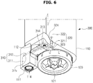
- FIG. 6 is a perspective view of an air inflow device equipped in the water tank of FIG. 4
- FIG. 7 is a cross-sectional view of the water tank of FIG. 4 viewed by cutting the air inflow device.
- the water tank 100 may include a body 110, and a cap 120 mounted on the bottom of the body 110.
- the cap 120 may include a cap airtight member 122 for airtightly close the water tank 100 while the cap 120 is combined with the body 110.
- the cap airtight member 122 may be formed of an elastic material, such as rubber.
- the cap 120 may also include a water supply inlet 121 for supplying water stored in the water tank 100 to the water reservoir 200.
- a water supply valve 123 may be arranged to open the water supply inlet 121 while the water tank 100 is mounted in the humidifier 1, and to close the water supply inlet 121 while the water tank 100 is separated from the humidifier 1.
- the water supply valve 123 may be installed in the water supply inlet 121 by means of an elastic member 124. At this time, when the water tank 100 is mounted in the water reservoir 200 of the humidifier 1, the water supply valve 123 may be pushed up by a projection (not shown) formed in the water reservoir 200, to open the water supply inlet 121.
- an air inflow device 300 may be equipped on the bottom side of the body 110 of the water tank 100, in accordance with an embodiment of the present disclosure.
- the air inflow device 300 may introduce an air inflow path 320, which is separate from the water supply unit 121, to force the air to flow in without passing through the water stored in the water tank 100.
- the air inflow device 300 may also include an open/close unit 310 to open or close the air inflow path 320.
- the open/close unit 310 may be contained in a housing 111 arranged on the bottom side of the body 110 of the water tank 100.
- the open/close unit 310 may include a float 311 that is moved by buoyant force according to the water level 201 of the water reservoir 200, and an open/close member 312 for opening or closing the air inflow path 320 according to a height of the float 311.
- the open/close member 312 and the float 311 may be hinged through a hinge connector 315.
- the hinge connector 315 may combine the open/close member 312 and the float 311 by combining a hinge projection formed on the open/close member 312 and a hinge projection receptor hole formed on the float 311.
- an opening 114 to allow water to flow in from the water reservoir 200 for the float 311 to be moved according to changes of the water level 201 of the water reservoir 200 may be formed below the float 311.
- the float 311 may be formed in the form of a recess with the bottom face opened to float in water, or in the form of a box with the inside empty and closed.
- the open/close member 312 has one end connected to the float 311 through the hinge connector 315, and the other end to be able to open/close the air inflow path 320.
- the ends of the open/close member 312 moves like a seesaw, in order for the open/close member 312 to open the air inflow path 320 if the float 311 falls, and to close the air inflow path 320 if the float 311 rises.
- the open/close member 312 may have a hinge projection 314 formed between both ends of the open/close member 312 to enable the ends to move like a seesaw.
- the hinge projection 314 of the open/close member 312 may be combined into a hinge projection receptor hole 112 formed in the housing 111.
- the air inflow path 320 may include an air inflow pipe 321 formed in the body 110 of the water tank 100, and an air tube 322 having one end connected to the air inflow pipe 321 to move the air upward of the inside of the water tank 100.
- the air flow inlet 323 is formed inside the housing 111 to be opened/closed by the open/close member 312, and the air tube connector projection 324 is arranged inside the body 110.
- the air tube 322 is formed of a rubber or plastic material to couple with the connector projection 324 by fitting the connector projection 324 into the air tube 322.
- the air tube 322 may be formed of a non-flexible material to be able to deliver air from an end where the cap 120 of the water tank 100 is placed to the other end, or may be formed of a flexible material with sufficient length.
- the open/close unit 310 may include an airtight member 313 formed to airtightly close the air flow path 320, specifically, the air flow inlet 323 of the air inflow pipe 321.
- the airtight member 313 may be formed of a material such as rubber.
- FIG. 8 is a cross-sectional view of the water tank of FIG. 4 for illustrating operations of the air inflow device and a check valve
- FIG. 9 is a cross-sectional view of the water tank of FIG. 4 for illustrating a check valve closed when the water tank is turned upside down.
- FIG. 10 is a perspective view of a check valve that may close the air tube during replenishment of water to the water tank.
- FIG. 11 illustrates a process of water supply from the water tank of FIG. 4 to the water reservoir.
- an end of the air tube 322 may be coupled with the connector projection 324 of the air inflow tube 321 inside the body 110 of the water tank 100.
- the check valve 400 may be arranged to prevent water contained in the water tank 100 from flowing into the air tube 322.
- the check valve 400 may include install members 410 to help the check valve 400 to be installed on the air tube 322.
- a hook 411 may be formed on the end of the install member 410 extending from the body of the check valve 400 to prevent it from being accidentally separated from the air tube 322.
- a hook receiver 322a may be formed on the end of the air tube 322 where the check valve 400 is mounted to catch the hook 411.
- the check valve 400 may include a recess 420 formed to close the air tube 322 by buoyant force of the water contained in the water tank 100 while the water tank is turned upside down with the cap 120 facing up.
- the float 311 of the open/close unit 310 may be moved up and down according to a height of the surface 201 of water of the water reservoir 200. As the float moves up and down, the end of the open/close member 312 coupled with the float 311 through the hinge connector 315 may also be moved up and down.
- the hinge projection 314 placed between the one end and the other end of the open/close member 312 may be mounted into the hinge projection receptor hole 112 of the housing 111.
- the other end of the open/close member 312 may also be moved up and down accordingly.
- This rotation movement (seesaw movement) of the open/close member 312 may enable the other end of the open/close member 312 to open or close the air flow inlet 323 of the air inflow pipe 321.
- the closing member 313 may be arranged on the other end of the open/close member 312, i.e., the end to open or close the air flow inlet 323 to airtightly close the air flow inlet 323. While the water tank 100 is mounted in the water reservoir 200, the air flow inlet 323 is arranged at a location farther away from the water reservoir 200 than from the water supply inlet 121 of the water tank 121. In other words, while the water tank 100 is mounted in the water reservoir 200, the air flow inlet 323 is arranged at a location higher than the water supply inlet 121 of the water tank 121.
- the water of the water reservoir 200 may not flow into the air flow inlet 323.
- the water of the water reservoir 200 may not flow into the air flow inlet 323 because the open/close member 312 airtightly closes the air flow inlet 323.
- the water level 201 of the water reservoir 200 falls.
- the float 311 may fall.
- the open/close member 312 turns around the hinge projection 314 to open the air flow inlet 323.
- the water of the water reservoir 200 may not flow into the air inflow pipe 321 even when the air flow inlet 323 is opened by the open/close member 312 because the air flow inlet 323 is first exposed to air when the water level 201 falls.
- the open/close member 312 opens the air flow inlet 323, outside air flows into the air inflow pipe 321, and the air flowing in (A) may be moved upward of the inside of the water tank 100 along the air tube 322. Due to the air inflow (A), the water stored in the water tank 100 may be supplied (B) to the water reservoir 200 through the water supply inlet 121.
- the water level 201 of the water reservoir 200 rises (D) again.
- the float 311 rises, causing the open/close member 312 to turn again around the hinge projection 314 to close the air flow inlet 323.
- the air flow inlet 323 is closed by the open/close member 312, a vacuum is created in the water tank 100, and the water supply (B) may be stopped by pressure equalization.
- the water tank 100 of the humidifier 1 in accordance with an embodiment of the present disclosure may maintain the water level 201 of the water reservoir 200 to a constant level while fundamentally preventing noise from being produced by air bubbles flowing into the water tank 100.
- FIGS. 12 to 17 Another embodiment in which an air inflow device of a water tank is installed on the cap of the water tank in accordance with the present disclosure will now be described in connection with FIGS. 12 to 17 .
- FIG. 12 is a front perspective view of a water tank, according to another embodiment of the present disclosure
- FIG. 13 is a perspective view of a bottom part of the water tank of FIG. 12 , from which a cap is pulled apart.
- FIG. 14 is a bottom perspective view of a cap of the water tank of FIG. 12
- FIG. 15 is an exploded view of a cap of the water tank of FIG. 12
- FIG. 16 is an exploded view of an open/close unit of the water tank of FIG. 12 .
- FIGS. 17A and 17B illustrate a process of water supply from the water tank of FIG. 12 to a water reservoir. Referring to FIG.
- the air inflow device 300 is not installed in the body of the water tank 100, but in the cap 120 of the water tank 100. Accordingly, unlike the water tank shown in FIG. 4 , no housing is formed in the body 110 of the water tank 100 to house the open/close unit 310.
- the cap 120 of the water tank 100 of FIG. 14 has the same basic structure as that of the cap of the water tank of FIG. 4 .
- the cap 120 may include the cap airtight member 122 for airtightly close the water tank 100 while the cap 120 is combined with the body 110.
- the cap airtight member 122 may be formed of an elastic material, such as rubber.
- the cap 120 may also include the water supply inlet 121 for supplying water stored in the water tank 100 to the water reservoir 200.
- the water supply valve 123 may be arranged to open the water supply inlet 121 while the water tank 100 is mounted in the humidifier 1, and to close the water supply inlet 121 while the water tank 100 is separated from the humidifier 1.
- the water supply valve 123 may be installed in the water supply inlet 121 by means of the elastic member 124. At this time, when the water tank 100 is mounted in the water reservoir 200 of the humidifier 1, the water supply valve 123 may be pushed up by a projection (not shown) formed in the water reservoir 200, to open the water supply inlet 121.
- the air inflow device 300 installed in the cap 120 may include the air inflow path 320, and the open/close unit 310 to open or close the air inflow path 320.
- the open/close unit 310 may include the float 311 that is moved by buoyant force according to the water level 201 of the water reservoir 200, and the open/close member 312 for opening or closing the air inflow path 320 according to a height of the float 311.
- the open/close member 312 and the float 311 may be hinged through the hinge connector 315.
- the hinge connector 315 may combine the open/close member 312 and the float 311 by combining a hinge projection 315a formed on the open/close member 312 and a hinge projection receptor hole 315b formed on the float 311.
- the float 311 may be formed in the form of a recess with the bottom face opened to float in water, or as shown in FIGS. 12 to 17 , in the form of a box with the inside empty and closed.
- the open/close member 312 has one end connected to the float 311 through the hinge connector 315, and the other end to open or close the air inflow path 320.
- the ends of the open/close member 312 moves like a seesaw, in order for the open/close member 312 to open the air inflow path 320 if the float 311 falls, and to close the air inflow path 320 if the float 311 rises.
- the open/close member 312 may have the hinge projection 314 formed between both ends of the open/close member 312 to enable the ends to move like a seesaw.
- the hinge projection 314 of the open/close member 312 may be combined into the hinge projection receptor hole 112 formed in the cap 120.
- the air inflow path 320 may include the air inflow pipe 321 formed in the cap 120 of the water tank 100, and the air tube 322 having one end connected to the air inflow pipe 321 to move the air upward of the inside of the water tank 100.
- the air flow inlet 323, which is opened or closed by the open/close unit 310, is formed on one end of the air inflow pipe 321, and the connection projection 324 to be connected to the air tube 322 is formed on the other end of the air inflow pipe 321.
- the air flow inlet 323 is formed outside the water tank 100 if the cap 120 is mounted in the body 110, to be opened or closed by the open/close member 312, and the air tube connector projection 324 is arranged inside the water tank 100.
- the air tube 322 is formed of a rubber or plastic material to couple with the connector projection 324 by fitting the connector projection 324 into the air tube 322.
- the air tube 322 may be formed of a non-flexible material to be able to deliver air from an end where the cap 120 is placed to the other end, or may be formed of a flexible material with sufficient length.
- the check valve 400 may be arranged to prevent the water contained in the water tank 100 from flowing into the air tube 322.
- the open/close unit 310 may include the airtight member 313 formed to airtightly close the air flow path 320, specifically, the air flow inlet 323 of the air inflow pipe 321.
- the airtight member 313 may be formed of a material such as rubber.
- the float 311 of the open/close unit 310 may be moved up and down according to the height of the surface 201 of water of the water reservoir 200. As the float 311 moves up and down, the end of the open/close member 312 coupled with the float 311 at the hinge connector 315 may also be moved up and down.
- the hinge projection 314 placed between the one end and the other end of the open/close member 312 may be mounted into the hinge projection receptor hole 112 formed in the cap 120.
- the other end of the open/close member 312 may also be moved up and down accordingly.
- This rotation movement (seesaw movement) of the open/close member 312 may enable the other end of the open/close member 312 to open or close the air flow inlet 323 of the air inflow pipe 321.
- the airtight member 313 may be arranged on the other end of the open/close member 312, i.e., the end to open or close the air flow inlet 323 to airtightly close the air flow inlet 323. While the water tank 100 is mounted in the water reservoir 200, the air flow inlet 323 is arranged at a location farther away from the water reservoir 200 than from the water supply inlet 121 of the water tank 121. In other words, while the water tank 100 is mounted in the water reservoir 200, the air flow inlet 323 is located higher than the water supply inlet 121 of the water tank 121.
- the water of the water reservoir 200 may not flow into the air flow inlet 323.
- the water of the water reservoir 200 may not flow into the air flow inlet 323 because the open/close member 312 airtightly closes the air flow inlet 323.
- the water level 201 of the water reservoir 200 falls.
- the float 311 may fall.
- the open/close member 312 turns around the hinge projection 314 to open the air flow inlet 323.
- the water of the water reservoir 200 may not flow into the air inflow pipe 321 even when the air flow inlet 323 is opened by the open/close member 312 because the air flow inlet 323 is first exposed to air when the water level 201 falls.
- the open/close member 312 opens the air flow inlet 323, outside air flows into the air inflow pipe 321, and the air flowing in (A) may be moved upward of the inside of the water tank 100 along the air tube 322. Due to the air inflow (A), the water stored in the water tank 100 may be supplied (B) to the water reservoir 200 through the water supply inlet 121.
- the water tank 100 of the humidifier 1 in accordance with an embodiment of the present disclosure may maintain the water level 201 of the water reservoir 200 to a constant level while fundamentally preventing noise from being produced by air bubbles flowing into the water tank 100.
- FIG. 18 is a bottom perspective view of a cap of a water tank, according to another embodiment of the present disclosure
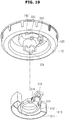
- FIG. 19 is a perspective view of a cap and an open/close unit of the water tank of FIG. 18 , which are pulled apart.
- FIGS. 20A and 20B illustrate a process of water supply from the water tank of FIG. 19 to a water reservoir.
- a basic structure of the cap 120 of the water tank 100 of FIG. 18 is the same as that of the cap of the water tank of FIG. 12 .
- the float 311 may be formed with the inside empty or closed as shown in FIGS. 12 to 17 in order to float in water, or may be formed in the form of a recess with the bottom face opened as shown in FIGS. 18 to 20 .
- the open/close unit 310 of the air inflow device 300 installed in the cap 120 of the water tank 100 of FIG. 18 may be formed to have the float 311 and the open/close member 312 integrated in one unit.
- the integration of the open/close unit 310 and the float 311 in one unit may reduce the number of constituent parts and simplify the structure.
- the open/close member 312 has one end integrally connected to the float 311, and the other end to be able to open or close the air inflow path 320.
- the ends of the open/close member 312 moves like a seesaw, in order for the open/close member 312 to open the air inflow path 320 if the float 311 falls, and to close the air inflow path 320 if the float 311 rises.
- the open/close member 312 may have the hinge projection 314 formed between both ends of the open/close member 312 to enable the ends to move like a seesaw.
- the hinge projection 314 of the open/close member 312 may be combined into the hinge projection receptor hole 112 formed in the cap 120.
- the float 311 of the open/close unit 310 may be moved up and down according to the height of the surface 201 of water of the water reservoir 200. As the float 311 connected to one end of the open/close member 312 moves up and down, the other end of the open/close member 312 may be moved up and down. This rotation movement (seesaw movement) of the open/close member 312 may enable the other end of the open/close member 312 to open or close the air flow inlet 323 of the air inflow pipe 321.
- the float 311 of the open/close unit 310 of FIGS. 20A and 20B may turn around the hinge projection 314.
- FIG. 21 is a perspective view of a water tank with a cap pulled apart, according to another embodiment of the present disclosure
- FIG. 22 is a bottom perspective view of a cap of the water tank of FIG. 21
- FIG. 23 is a perspective view of a cap and an open/close unit of the water tank of FIG. 21 , which are pulled apart.
- FIGS. 24A and 24B illustrate a process of water supply from the water tank of FIG. 21 to a water reservoir.
- a basic structure of the cap 120 of the water tank 100 of FIG. 21 is the same as that of the cap of the water tank of FIG. 12 . Description of the same parts of the structure will be omitted herein.
- the air inflow device 300 installed in the cap 120 may include the air inflow path 320, and the float 311 to open or close the air inflow path 320. That is, the open/close unit may be configured only with the float 311.
- the float 311 may be moved by buoyant force according to the water level 201 of the water reservoir 200, and the air inflow path 320 may be opened or closed according to the height of the float 311.
- the open/close member 312 may open the air inflow path 320 if the float 311 falls, and may close the air inflow path 320 if the float 311 rises.
- the float 311 may be formed with the inside empty or closed in order to float in water, or may be formed in the form of a recess with the bottom face opened as shown in FIGS. 21 to 24 .
- the cap 120 may include an anti-separation structure 125 to prevent accidental separation of the float 311.
- the float 311 may have the form similar to a tire, which encloses the water supply inlet 121, and may be mounted in the cap 120 to enclose the water supply inlet 121.
- the anti-separation structure 125 may be formed at the end of the water supply inlet 121.
- the air inflow path 320 may include the air inflow pipe 321 formed in the cap 120 of the water tank 100, and the air tube 322 having one end connected to the air inflow pipe 321 to move the air upward of the inside of the water tank.
- the air flow inlet 323, which is opened or closed by the float 311, is formed on one end of the air inflow pipe 321, and the connector projection 324 to be connected to the air tube 322 is formed on the other end of the air inflow pipe 321.
- the air flow inlet 323 is formed outside the water tank 100 if the cap 120 is mounted in the body 110, to be opened or closed by the open/close member 311, and the air tube connector projection 324 is arranged inside the water tank 100.
- the float 311 may include the airtight member 313 formed to airtightly close the air flow path 320, specifically, the air flow inlet 323 of the air inflow pipe 321.
- the airtight member 313 may be formed of a material such as rubber.
- the cap 120 may include a supporting protrusion 126 formed to facilitate the float 311 to open or close the air flow inlet 323 by remaining level when the float 311 rises.
- the float 311 may be moved up and down according to the height of the surface 201 of water of the water reservoir 200. If the water level 201 of the water reservoir 200 increases, the float 311 may rise until the air flow inlet 323 and the supporting protrusion 126 come into contact with each other, to close the air flow inlet 323. If the water level 201 of the water reservoir 200 decreases, the float 311 falls until coming into contact with the anti-separation structure 125, to open the air flow inlet 323.
- a home appliance equipped with the humidifier or water tank in accordance with the embodiments of the present disclosure may maintain a silent state of operation in an environment requiring low noise, and automatically control the water level by means of buoyant force without use of an electric valve unit, thereby reducing the manufacturing costs and achieving structural improvement.
- the open/close unit may not be able to close the air inflow path due to a malfunction of the air inflow device of the home appliance equipped with the humidifier or water tank in accordance with the embodiments of the present disclosure, when the air flow inlet of the air inflow path is closed as the water level of the water reservoir increases, air inflow is blocked and water supply is stopped, thereby enabling normal water supply without overflowing of water from the water reservoir.
- an air inflow path introduced separately from a water supply inlet in a water tank of a humidifier prevents noise generation due to air bubbles while water is supplied to a water reservoir from the water tank.
- the air inflow path may be blocked to prevent water from flowing into the air inflow path during replenishment of water to the water tank of the humidifier.
Claims (10)
- Haushaltsgerät (1), umfassend:einen Wassertank (100), der eine Lufteintrittsvorrichtung (300) umfasst; undeinen Wasserbehälter (200), der ausgelegt ist, das von dem Wassertank (100) eintretende Wasser zu fassen,wobei die Lufteintrittsvorrichtung (300) einen Lufteintrittspfad (320), der von dem Wasser, das von dem Wassertank (100) in den Wasserbehälter (200) eintritt, getrennt ist, und eine Öffnungs-/Schließeinheit (310), die ausgelegt ist, den Lufteintrittspfad (320) zu öffnen oder schließen, umfasst, dadurch gekennzeichnet, dass die Öffnungs-/Schließeinheit (310) Folgendes umfasst:einen Schwimmkörper (311), der ausgelegt ist, sich gemäß einem Wasserpegel des Wasserbehälters (200) zu bewegen; undein Öffnungs-/Schließbauteil (312), das ausgelegt ist, den Lufteintrittspfad (320) gemäß einer Höhe des Schwimmkörpers (311) zu öffnen oder schließen, wobei das Öffnungs-/Schließbauteil (312) ferner ausgelegt ist zum:Öffnen des Lufteintrittspfads (320), wenn der Schwimmkörper (311) sinkt, undSchließen des Lufteintrittspfads (320), wenn der Schwimmkörper (311) steigt.
- Haushaltsgerät (1) nach Anspruch 1, ferner umfassend ein Befeuchtungselement (70), das ausgelegt ist, eine Befeuchtung mit zugeführtem Wasser, das in dem Wasserbehälter (200) gefasst ist, durchzuführen.
- Haushaltsgerät (1) nach einem der vorhergehenden Ansprüche, wobei der Lufteintrittspfad (320) Folgendes umfasst:eine Lufteintrittsleitung (321), die ausgelegt ist, um durch die Öffnungs-/Schließeinheit (310) geöffnet oder geschlossen zu werden; undein Luftröhre (322), die mit der Lufteintrittsleitung (321) verbunden ist.
- Haushaltsgerät (1) nach einem der vorhergehenden Ansprüche, wobei die Öffnungs-/Schließeinheit (310) ein hermetisches Bauteil (313) umfasst, das zum hermetischen Schließen des Lufteintrittspfads (320) ausgebildet ist.
- Haushaltsgerät (1) nach einem der vorhergehenden Ansprüche, wobei die Lufteintrittsvorrichtung (300) ein Rückschlagventil (400) umfasst, das ausgelegt ist, Wasser daran zu hindern, während des Befüllens des Wassertanks (100) mit Wasser von dem Wassertank (100) in den Lufteintrittspfad (320) zu fließen.
- Haushaltsgerät (1) nach Anspruch 5, wobei das Rückschlagventil (400) eine Vertiefung (420) umfasst, die zum Aufnehmen von Auftrieb ausgebildet ist.
- Haushaltsgerät (1) nach einem der vorhergehenden Ansprüche,
wobei der Wassertank (100) einen Körper (110) und einen Deckel (120) umfasst;
wobei der Deckel (120) des Wassertanks (100) mit einem Wasserzufuhreinlass (121) ausgestattet ist, der ausgelegt ist, um dem Wasserbehälter (200) Wasser zuzuführen, und
wobei der Körper (110) des Wassertanks mit dem Lufteintrittspfad (320) und der Öffnungs-/Schließeinheit (310) ausgestattet ist. - Haushaltsgerät (1) nach einem der vorhergehenden Ansprüche einschließlich der Ansprüche 1 und 3,
wobei die Lufteintrittsleitung (321) ausgelegt ist, durch das Öffnungs-/Schließbauteil (312) geöffnet oder geschlossen zu werden. - Haushaltsgerät (1) nach einem der vorhergehenden Ansprüche einschließlich der Ansprüche 3 und 4, wobei das hermetische Bauteil (313) ausgelegt ist, einen Luftstromeinlass (323) einer Lufteintrittsleitung (321) hermetisch zu verschließen.
- Haushaltsgerät (1) nach Anspruch 9, wobei der Luftstromeinlass (323) der Lufteintrittsleitung (321) weiter weg von dem Wasserbehälter (200) als von dem Wasserzufuhreinlass (121) angeordnet ist,
wobei der Luftstromeinlass (323) Luft ausgesetzt ist, wenn ein Wasserpegel des Wasserbehälters (200) sich verringert, und das Öffnungs-/Schließbauteil (312) ausgelegt ist, den Luftstromeinlass (323) zu öffnen, wenn der Schwimmkörper (311) sinkt, und
wobei der Schwimmkörper (311) ausgelegt ist, wieder zu steigen und das Öffnungs-/Schließbauteil (312) zu aktivieren, den Luftstromeinlass (323) wieder zu verschließen, wenn Wasser aus dem Wassertank (100) durch den Wasserzufuhreinlass (121) in den Wasserbehälter (200) fließt.
Applications Claiming Priority (1)
| Application Number | Priority Date | Filing Date | Title |
|---|---|---|---|
| KR1020150053883A KR102466276B1 (ko) | 2015-04-16 | 2015-04-16 | 가습기 및 가전기기 |
Publications (2)
| Publication Number | Publication Date |
|---|---|
| EP3081872A1 EP3081872A1 (de) | 2016-10-19 |
| EP3081872B1 true EP3081872B1 (de) | 2020-06-17 |
Family
ID=55527408
Family Applications (1)
| Application Number | Title | Priority Date | Filing Date |
|---|---|---|---|
| EP16159876.8A Active EP3081872B1 (de) | 2015-04-16 | 2016-03-11 | Haushaltsgerät |
Country Status (6)
| Country | Link |
|---|---|
| US (2) | US10436466B2 (de) |
| EP (1) | EP3081872B1 (de) |
| KR (1) | KR102466276B1 (de) |
| CN (2) | CN111238020B (de) |
| AU (1) | AU2016249637B2 (de) |
| WO (1) | WO2016167465A1 (de) |
Families Citing this family (14)
| Publication number | Priority date | Publication date | Assignee | Title |
|---|---|---|---|---|
| US11549699B2 (en) * | 2017-10-03 | 2023-01-10 | Vornado Air, Llc | Portable humidifier |
| JP1631156S (de) * | 2018-05-10 | 2019-05-13 | ||
| CN108825803A (zh) * | 2018-08-27 | 2018-11-16 | 珠海格力电器股份有限公司 | 出水阀结构及包括其的加湿器 |
| CN109373443B (zh) * | 2018-10-18 | 2021-11-19 | 广东美的制冷设备有限公司 | 空调的水箱组件以及空调室内机 |
| CN109708230B (zh) * | 2018-12-19 | 2021-08-31 | 浙江黄岩康宝利清香剂厂 | 一种气体湿化装置 |
| GB201900018D0 (en) * | 2019-01-02 | 2019-02-13 | Dyson Technology Ltd | Air treatment apparatus |
| KR102340052B1 (ko) * | 2019-01-03 | 2021-12-16 | 코웨이 주식회사 | 가습기 |
| CN110186139A (zh) * | 2019-05-29 | 2019-08-30 | 深圳市晨北科技有限公司 | 一种防水装置及加湿器 |
| CN110274337A (zh) * | 2019-06-14 | 2019-09-24 | 深圳市晨北科技有限公司 | 一种加湿器 |
| KR20200144003A (ko) * | 2019-06-17 | 2020-12-28 | 코웨이 주식회사 | 가습청정기 |
| JP1686298S (de) * | 2019-12-23 | 2021-05-31 | ||
| KR20210101899A (ko) * | 2020-02-11 | 2021-08-19 | 삼성전자주식회사 | 가습장치 |
| JP1705360S (ja) * | 2020-10-15 | 2022-01-19 | 空気清浄機 | |
| WO2023281292A1 (en) * | 2021-07-04 | 2023-01-12 | Okhotnikov Kirill | Noise reducing device for apparatus to be filled with water |
Citations (4)
| Publication number | Priority date | Publication date | Assignee | Title |
|---|---|---|---|---|
| US4765327A (en) * | 1986-12-19 | 1988-08-23 | Respiratory Care, Inc. | Cartridge humidifier vent valve |
| JP3110210U (ja) * | 2005-01-14 | 2005-06-16 | 有限会社アイ・シー・アイデザイン研究所 | 加湿器 |
| KR20080014165A (ko) * | 2006-08-10 | 2008-02-14 | 위니아만도 주식회사 | 가습기 및 가습기용 보충수 물통 |
| JP2010196933A (ja) * | 2009-02-24 | 2010-09-09 | Tiger Vacuum Bottle Co Ltd | 水供給装置 |
Family Cites Families (28)
| Publication number | Priority date | Publication date | Assignee | Title |
|---|---|---|---|---|
| US4500480A (en) * | 1982-08-23 | 1985-02-19 | Respiratory Care, Inc. | Pediatric cartridge humidifier |
| US4489744A (en) * | 1982-09-27 | 1984-12-25 | The United States Of America As Represented By The United States Department Of Energy | Liquid blocking check valve |
| US5431290A (en) * | 1992-03-24 | 1995-07-11 | Vinciguerra; Mark T. | Baby bottle for improved flow |
| JP3110210B2 (ja) * | 1993-06-24 | 2000-11-20 | 日本電気株式会社 | データ分析支援方法 |
| KR960001651A (ko) | 1994-06-22 | 1996-01-25 | 이헌조 | 가습기의 이상소음 제거방법 및 장치 |
| US5547615A (en) * | 1995-05-10 | 1996-08-20 | Duracraft Corporation | Portable humidifier with bacteriastat dispenser |
| US6248155B1 (en) * | 1999-08-13 | 2001-06-19 | Bemis Manufacturing Company | Combination humidifier and air purifier |
| US20030016952A1 (en) * | 2001-07-10 | 2003-01-23 | Elphee David Andrew | Low-maintenance humidifier |
| JP2003240282A (ja) * | 2002-02-14 | 2003-08-27 | Kunio Takagi | 非接触型パイプ式排水バルブ装置 |
| DE10234811C1 (de) * | 2002-07-31 | 2003-11-27 | Draeger Medical Ag | Atemgasanfeuchtersystem für einen Patienten |
| US6988497B2 (en) * | 2002-09-18 | 2006-01-24 | Medex Cardio-Pulmonary, Inc. | Apparatus for equalizing air pressure in air respiratory system |
| DE10251134A1 (de) * | 2002-10-31 | 2004-05-19 | GRÜNDLER GmbH | Beatmungsvorrichtung und Verfahren |
| US7228859B2 (en) * | 2004-06-29 | 2007-06-12 | Teleflex Medical Incorporated | Pressure venting circuit for respiratory humidification apparatus |
| US7722016B2 (en) * | 2006-08-31 | 2010-05-25 | Medex Cardio-Pulmonary, Inc. | Float for humidification chamber |
| JP4726760B2 (ja) | 2006-10-06 | 2011-07-20 | 三菱電機株式会社 | 加湿器及び機器 |
| US20080093750A1 (en) * | 2006-10-18 | 2008-04-24 | Zhijing Wang | Dual inlet water tank for a humidifier |
| DE102009011137A1 (de) * | 2009-03-03 | 2010-09-09 | Seleon Gmbh | Verdunstungskammer, Zwischenkammer sowie Verfahren |
| US9285130B2 (en) * | 2010-12-23 | 2016-03-15 | Lg Electronics Inc. | Air conditioner |
| JP2013002797A (ja) * | 2011-06-22 | 2013-01-07 | Panasonic Corp | 加湿器 |
| KR101163721B1 (ko) | 2011-11-09 | 2012-07-09 | 와토스코리아 주식회사 | 로우탱크 양변기의 림부 급수 전환장치 |
| US10213573B2 (en) * | 2011-12-22 | 2019-02-26 | Resmed Limited | Humidifiers for respiratory apparatus |
| US8701701B2 (en) * | 2012-09-25 | 2014-04-22 | Chin-Cheng Huang | Float switch of a humidifier |
| US9360227B2 (en) * | 2013-03-15 | 2016-06-07 | Helen Of Troy Limited | Removable top fill tank |
| KR102125718B1 (ko) * | 2013-06-05 | 2020-06-23 | 삼성전자주식회사 | 정수필터장치 및 이를 포함하는 가습기 |
| CN204202075U (zh) * | 2014-10-22 | 2015-03-11 | 厦门蒙发利健康科技有限公司 | 一种静音型加湿机 |
| CN204202078U (zh) * | 2014-10-22 | 2015-03-11 | 漳州蒙发利实业有限公司 | 一种空气增湿器 |
| JP5915725B1 (ja) * | 2014-12-26 | 2016-05-11 | ダイキン工業株式会社 | 水処理装置 |
| US10168064B1 (en) * | 2018-07-13 | 2019-01-01 | Zhongshan Titan Arts & Crafts Co., Ltd. | Ultrasonic humidifier |
-
2015
- 2015-04-16 KR KR1020150053883A patent/KR102466276B1/ko active IP Right Grant
-
2016
- 2016-02-23 AU AU2016249637A patent/AU2016249637B2/en not_active Ceased
- 2016-02-23 WO PCT/KR2016/001733 patent/WO2016167465A1/en active Application Filing
- 2016-02-23 CN CN202010181188.XA patent/CN111238020B/zh active Active
- 2016-02-23 CN CN201680035070.8A patent/CN107810370B/zh active Active
- 2016-03-11 EP EP16159876.8A patent/EP3081872B1/de active Active
- 2016-03-25 US US15/081,658 patent/US10436466B2/en active Active
-
2019
- 2019-08-30 US US16/557,829 patent/US10808952B2/en active Active
Patent Citations (4)
| Publication number | Priority date | Publication date | Assignee | Title |
|---|---|---|---|---|
| US4765327A (en) * | 1986-12-19 | 1988-08-23 | Respiratory Care, Inc. | Cartridge humidifier vent valve |
| JP3110210U (ja) * | 2005-01-14 | 2005-06-16 | 有限会社アイ・シー・アイデザイン研究所 | 加湿器 |
| KR20080014165A (ko) * | 2006-08-10 | 2008-02-14 | 위니아만도 주식회사 | 가습기 및 가습기용 보충수 물통 |
| JP2010196933A (ja) * | 2009-02-24 | 2010-09-09 | Tiger Vacuum Bottle Co Ltd | 水供給装置 |
Also Published As
| Publication number | Publication date |
|---|---|
| CN107810370B (zh) | 2020-04-10 |
| KR20160123624A (ko) | 2016-10-26 |
| EP3081872A1 (de) | 2016-10-19 |
| AU2016249637B2 (en) | 2020-11-12 |
| AU2016249637A1 (en) | 2017-11-02 |
| CN107810370A (zh) | 2018-03-16 |
| CN111238020B (zh) | 2021-08-17 |
| US20190383503A1 (en) | 2019-12-19 |
| CN111238020A (zh) | 2020-06-05 |
| US10436466B2 (en) | 2019-10-08 |
| US10808952B2 (en) | 2020-10-20 |
| WO2016167465A1 (en) | 2016-10-20 |
| US20160305674A1 (en) | 2016-10-20 |
| KR102466276B1 (ko) | 2022-11-11 |
Similar Documents
| Publication | Publication Date | Title |
|---|---|---|
| EP3081872B1 (de) | Haushaltsgerät | |
| US9423141B2 (en) | Console humidifier | |
| KR102340052B1 (ko) | 가습기 | |
| US10228150B2 (en) | Humidifying apparatus | |
| US20230093557A1 (en) | Humidifier | |
| CN101749821A (zh) | 加湿器 | |
| KR102046476B1 (ko) | 누수 방지가 가능한 가습 장치 | |
| JP2010019445A (ja) | 加湿機 | |
| JP6633015B2 (ja) | 加湿装置 | |
| JP2008039326A (ja) | 加湿装置 | |
| WO2020207283A1 (zh) | 蒸汽发生装置以及空气调节装置 | |
| JP4648256B2 (ja) | 給水装置 | |
| KR102237457B1 (ko) | 급수형 에어워셔 | |
| JP2008020115A (ja) | 給水装置 | |
| JP2010164265A (ja) | 加湿器 | |
| KR20130074164A (ko) | 가습공기청정기 | |
| KR102360877B1 (ko) | 가습기 및 가전기기 | |
| JP6912424B2 (ja) | 加湿装置 | |
| JPWO2015182738A1 (ja) | 空気調和器 | |
| CN213747007U (zh) | 空气处理装置的加湿装置、空气处理装置和空调室内机 | |
| JP7348537B2 (ja) | 加湿装置 | |
| JP2010196933A (ja) | 水供給装置 | |
| KR101710166B1 (ko) | 벽걸이형 가습기 | |
| CN116447663A (zh) | 加湿系统、空调室内机以及控制方法 | |
| WO2021017221A1 (zh) | 加湿装置和具有其的空调器 |
Legal Events
| Date | Code | Title | Description |
|---|---|---|---|
| PUAI | Public reference made under article 153(3) epc to a published international application that has entered the european phase |
Free format text: ORIGINAL CODE: 0009012 |
|
| AK | Designated contracting states |
Kind code of ref document: A1 Designated state(s): AL AT BE BG CH CY CZ DE DK EE ES FI FR GB GR HR HU IE IS IT LI LT LU LV MC MK MT NL NO PL PT RO RS SE SI SK SM TR |
|
| AX | Request for extension of the european patent |
Extension state: BA ME |
|
| STAA | Information on the status of an ep patent application or granted ep patent |
Free format text: STATUS: REQUEST FOR EXAMINATION WAS MADE |
|
| 17P | Request for examination filed |
Effective date: 20161222 |
|
| RBV | Designated contracting states (corrected) |
Designated state(s): AL AT BE BG CH CY CZ DE DK EE ES FI FR GB GR HR HU IE IS IT LI LT LU LV MC MK MT NL NO PL PT RO RS SE SI SK SM TR |
|
| STAA | Information on the status of an ep patent application or granted ep patent |
Free format text: STATUS: EXAMINATION IS IN PROGRESS |
|
| 17Q | First examination report despatched |
Effective date: 20170830 |
|
| GRAP | Despatch of communication of intention to grant a patent |
Free format text: ORIGINAL CODE: EPIDOSNIGR1 |
|
| STAA | Information on the status of an ep patent application or granted ep patent |
Free format text: STATUS: GRANT OF PATENT IS INTENDED |
|
| RIC1 | Information provided on ipc code assigned before grant |
Ipc: F24F 13/24 20060101ALI20200129BHEP Ipc: F24F 6/00 20060101AFI20200129BHEP Ipc: F24F 6/16 20060101ALI20200129BHEP Ipc: F24F 11/74 20180101ALI20200129BHEP |
|
| INTG | Intention to grant announced |
Effective date: 20200217 |
|
| GRAS | Grant fee paid |
Free format text: ORIGINAL CODE: EPIDOSNIGR3 |
|
| GRAA | (expected) grant |
Free format text: ORIGINAL CODE: 0009210 |
|
| STAA | Information on the status of an ep patent application or granted ep patent |
Free format text: STATUS: THE PATENT HAS BEEN GRANTED |
|
| AK | Designated contracting states |
Kind code of ref document: B1 Designated state(s): AL AT BE BG CH CY CZ DE DK EE ES FI FR GB GR HR HU IE IS IT LI LT LU LV MC MK MT NL NO PL PT RO RS SE SI SK SM TR |
|
| REG | Reference to a national code |
Ref country code: GB Ref legal event code: FG4D |
|
| REG | Reference to a national code |
Ref country code: CH Ref legal event code: EP |
|
| REG | Reference to a national code |
Ref country code: IE Ref legal event code: FG4D |
|
| REG | Reference to a national code |
Ref country code: DE Ref legal event code: R096 Ref document number: 602016038072 Country of ref document: DE |
|
| REG | Reference to a national code |
Ref country code: AT Ref legal event code: REF Ref document number: 1281779 Country of ref document: AT Kind code of ref document: T Effective date: 20200715 |
|
| PG25 | Lapsed in a contracting state [announced via postgrant information from national office to epo] |
Ref country code: FI Free format text: LAPSE BECAUSE OF FAILURE TO SUBMIT A TRANSLATION OF THE DESCRIPTION OR TO PAY THE FEE WITHIN THE PRESCRIBED TIME-LIMIT Effective date: 20200617 Ref country code: NO Free format text: LAPSE BECAUSE OF FAILURE TO SUBMIT A TRANSLATION OF THE DESCRIPTION OR TO PAY THE FEE WITHIN THE PRESCRIBED TIME-LIMIT Effective date: 20200917 Ref country code: GR Free format text: LAPSE BECAUSE OF FAILURE TO SUBMIT A TRANSLATION OF THE DESCRIPTION OR TO PAY THE FEE WITHIN THE PRESCRIBED TIME-LIMIT Effective date: 20200918 Ref country code: SE Free format text: LAPSE BECAUSE OF FAILURE TO SUBMIT A TRANSLATION OF THE DESCRIPTION OR TO PAY THE FEE WITHIN THE PRESCRIBED TIME-LIMIT Effective date: 20200617 Ref country code: LT Free format text: LAPSE BECAUSE OF FAILURE TO SUBMIT A TRANSLATION OF THE DESCRIPTION OR TO PAY THE FEE WITHIN THE PRESCRIBED TIME-LIMIT Effective date: 20200617 |
|
| REG | Reference to a national code |
Ref country code: LT Ref legal event code: MG4D |
|
| REG | Reference to a national code |
Ref country code: NL Ref legal event code: MP Effective date: 20200617 |
|
| PG25 | Lapsed in a contracting state [announced via postgrant information from national office to epo] |
Ref country code: RS Free format text: LAPSE BECAUSE OF FAILURE TO SUBMIT A TRANSLATION OF THE DESCRIPTION OR TO PAY THE FEE WITHIN THE PRESCRIBED TIME-LIMIT Effective date: 20200617 Ref country code: BG Free format text: LAPSE BECAUSE OF FAILURE TO SUBMIT A TRANSLATION OF THE DESCRIPTION OR TO PAY THE FEE WITHIN THE PRESCRIBED TIME-LIMIT Effective date: 20200917 Ref country code: LV Free format text: LAPSE BECAUSE OF FAILURE TO SUBMIT A TRANSLATION OF THE DESCRIPTION OR TO PAY THE FEE WITHIN THE PRESCRIBED TIME-LIMIT Effective date: 20200617 Ref country code: HR Free format text: LAPSE BECAUSE OF FAILURE TO SUBMIT A TRANSLATION OF THE DESCRIPTION OR TO PAY THE FEE WITHIN THE PRESCRIBED TIME-LIMIT Effective date: 20200617 |
|
| REG | Reference to a national code |
Ref country code: AT Ref legal event code: MK05 Ref document number: 1281779 Country of ref document: AT Kind code of ref document: T Effective date: 20200617 |
|
| PG25 | Lapsed in a contracting state [announced via postgrant information from national office to epo] |
Ref country code: AL Free format text: LAPSE BECAUSE OF FAILURE TO SUBMIT A TRANSLATION OF THE DESCRIPTION OR TO PAY THE FEE WITHIN THE PRESCRIBED TIME-LIMIT Effective date: 20200617 Ref country code: NL Free format text: LAPSE BECAUSE OF FAILURE TO SUBMIT A TRANSLATION OF THE DESCRIPTION OR TO PAY THE FEE WITHIN THE PRESCRIBED TIME-LIMIT Effective date: 20200617 |
|
| PG25 | Lapsed in a contracting state [announced via postgrant information from national office to epo] |
Ref country code: ES Free format text: LAPSE BECAUSE OF FAILURE TO SUBMIT A TRANSLATION OF THE DESCRIPTION OR TO PAY THE FEE WITHIN THE PRESCRIBED TIME-LIMIT Effective date: 20200617 Ref country code: EE Free format text: LAPSE BECAUSE OF FAILURE TO SUBMIT A TRANSLATION OF THE DESCRIPTION OR TO PAY THE FEE WITHIN THE PRESCRIBED TIME-LIMIT Effective date: 20200617 Ref country code: AT Free format text: LAPSE BECAUSE OF FAILURE TO SUBMIT A TRANSLATION OF THE DESCRIPTION OR TO PAY THE FEE WITHIN THE PRESCRIBED TIME-LIMIT Effective date: 20200617 Ref country code: IT Free format text: LAPSE BECAUSE OF FAILURE TO SUBMIT A TRANSLATION OF THE DESCRIPTION OR TO PAY THE FEE WITHIN THE PRESCRIBED TIME-LIMIT Effective date: 20200617 Ref country code: SM Free format text: LAPSE BECAUSE OF FAILURE TO SUBMIT A TRANSLATION OF THE DESCRIPTION OR TO PAY THE FEE WITHIN THE PRESCRIBED TIME-LIMIT Effective date: 20200617 Ref country code: CZ Free format text: LAPSE BECAUSE OF FAILURE TO SUBMIT A TRANSLATION OF THE DESCRIPTION OR TO PAY THE FEE WITHIN THE PRESCRIBED TIME-LIMIT Effective date: 20200617 Ref country code: RO Free format text: LAPSE BECAUSE OF FAILURE TO SUBMIT A TRANSLATION OF THE DESCRIPTION OR TO PAY THE FEE WITHIN THE PRESCRIBED TIME-LIMIT Effective date: 20200617 Ref country code: PT Free format text: LAPSE BECAUSE OF FAILURE TO SUBMIT A TRANSLATION OF THE DESCRIPTION OR TO PAY THE FEE WITHIN THE PRESCRIBED TIME-LIMIT Effective date: 20201019 |
|
| PG25 | Lapsed in a contracting state [announced via postgrant information from national office to epo] |
Ref country code: PL Free format text: LAPSE BECAUSE OF FAILURE TO SUBMIT A TRANSLATION OF THE DESCRIPTION OR TO PAY THE FEE WITHIN THE PRESCRIBED TIME-LIMIT Effective date: 20200617 Ref country code: SK Free format text: LAPSE BECAUSE OF FAILURE TO SUBMIT A TRANSLATION OF THE DESCRIPTION OR TO PAY THE FEE WITHIN THE PRESCRIBED TIME-LIMIT Effective date: 20200617 Ref country code: IS Free format text: LAPSE BECAUSE OF FAILURE TO SUBMIT A TRANSLATION OF THE DESCRIPTION OR TO PAY THE FEE WITHIN THE PRESCRIBED TIME-LIMIT Effective date: 20201017 |
|
| REG | Reference to a national code |
Ref country code: DE Ref legal event code: R097 Ref document number: 602016038072 Country of ref document: DE |
|
| PLBE | No opposition filed within time limit |
Free format text: ORIGINAL CODE: 0009261 |
|
| STAA | Information on the status of an ep patent application or granted ep patent |
Free format text: STATUS: NO OPPOSITION FILED WITHIN TIME LIMIT |
|
| PG25 | Lapsed in a contracting state [announced via postgrant information from national office to epo] |
Ref country code: DK Free format text: LAPSE BECAUSE OF FAILURE TO SUBMIT A TRANSLATION OF THE DESCRIPTION OR TO PAY THE FEE WITHIN THE PRESCRIBED TIME-LIMIT Effective date: 20200617 |
|
| 26N | No opposition filed |
Effective date: 20210318 |
|
| PG25 | Lapsed in a contracting state [announced via postgrant information from national office to epo] |
Ref country code: SI Free format text: LAPSE BECAUSE OF FAILURE TO SUBMIT A TRANSLATION OF THE DESCRIPTION OR TO PAY THE FEE WITHIN THE PRESCRIBED TIME-LIMIT Effective date: 20200617 |
|
| PG25 | Lapsed in a contracting state [announced via postgrant information from national office to epo] |
Ref country code: MC Free format text: LAPSE BECAUSE OF FAILURE TO SUBMIT A TRANSLATION OF THE DESCRIPTION OR TO PAY THE FEE WITHIN THE PRESCRIBED TIME-LIMIT Effective date: 20200617 |
|
| REG | Reference to a national code |
Ref country code: CH Ref legal event code: PL |
|
| REG | Reference to a national code |
Ref country code: BE Ref legal event code: MM Effective date: 20210331 |
|
| PG25 | Lapsed in a contracting state [announced via postgrant information from national office to epo] |
Ref country code: LI Free format text: LAPSE BECAUSE OF NON-PAYMENT OF DUE FEES Effective date: 20210331 Ref country code: LU Free format text: LAPSE BECAUSE OF NON-PAYMENT OF DUE FEES Effective date: 20210311 Ref country code: CH Free format text: LAPSE BECAUSE OF NON-PAYMENT OF DUE FEES Effective date: 20210331 Ref country code: IE Free format text: LAPSE BECAUSE OF NON-PAYMENT OF DUE FEES Effective date: 20210311 Ref country code: FR Free format text: LAPSE BECAUSE OF NON-PAYMENT OF DUE FEES Effective date: 20210331 |
|
| PG25 | Lapsed in a contracting state [announced via postgrant information from national office to epo] |
Ref country code: BE Free format text: LAPSE BECAUSE OF NON-PAYMENT OF DUE FEES Effective date: 20210331 |
|
| PG25 | Lapsed in a contracting state [announced via postgrant information from national office to epo] |
Ref country code: HU Free format text: LAPSE BECAUSE OF FAILURE TO SUBMIT A TRANSLATION OF THE DESCRIPTION OR TO PAY THE FEE WITHIN THE PRESCRIBED TIME-LIMIT; INVALID AB INITIO Effective date: 20160311 |
|
| PGFP | Annual fee paid to national office [announced via postgrant information from national office to epo] |
Ref country code: GB Payment date: 20230220 Year of fee payment: 8 Ref country code: DE Payment date: 20230220 Year of fee payment: 8 |
|
| PG25 | Lapsed in a contracting state [announced via postgrant information from national office to epo] |
Ref country code: CY Free format text: LAPSE BECAUSE OF FAILURE TO SUBMIT A TRANSLATION OF THE DESCRIPTION OR TO PAY THE FEE WITHIN THE PRESCRIBED TIME-LIMIT Effective date: 20200617 |
|
| PG25 | Lapsed in a contracting state [announced via postgrant information from national office to epo] |
Ref country code: MK Free format text: LAPSE BECAUSE OF FAILURE TO SUBMIT A TRANSLATION OF THE DESCRIPTION OR TO PAY THE FEE WITHIN THE PRESCRIBED TIME-LIMIT Effective date: 20200617 |
|
| PGFP | Annual fee paid to national office [announced via postgrant information from national office to epo] |
Ref country code: DE Payment date: 20240220 Year of fee payment: 9 |