EP3081872B1 - Home appliance - Google Patents
Home appliance Download PDFInfo
- Publication number
- EP3081872B1 EP3081872B1 EP16159876.8A EP16159876A EP3081872B1 EP 3081872 B1 EP3081872 B1 EP 3081872B1 EP 16159876 A EP16159876 A EP 16159876A EP 3081872 B1 EP3081872 B1 EP 3081872B1
- Authority
- EP
- European Patent Office
- Prior art keywords
- water
- open
- close
- air inflow
- water tank
- Prior art date
- Legal status (The legal status is an assumption and is not a legal conclusion. Google has not performed a legal analysis and makes no representation as to the accuracy of the status listed.)
- Active
Links
Images


Classifications
-
- F—MECHANICAL ENGINEERING; LIGHTING; HEATING; WEAPONS; BLASTING
- F24—HEATING; RANGES; VENTILATING
- F24F—AIR-CONDITIONING; AIR-HUMIDIFICATION; VENTILATION; USE OF AIR CURRENTS FOR SCREENING
- F24F6/00—Air-humidification, e.g. cooling by humidification
- F24F6/02—Air-humidification, e.g. cooling by humidification by evaporation of water in the air
-
- F—MECHANICAL ENGINEERING; LIGHTING; HEATING; WEAPONS; BLASTING
- F24—HEATING; RANGES; VENTILATING
- F24F—AIR-CONDITIONING; AIR-HUMIDIFICATION; VENTILATION; USE OF AIR CURRENTS FOR SCREENING
- F24F6/00—Air-humidification, e.g. cooling by humidification
-
- F—MECHANICAL ENGINEERING; LIGHTING; HEATING; WEAPONS; BLASTING
- F24—HEATING; RANGES; VENTILATING
- F24F—AIR-CONDITIONING; AIR-HUMIDIFICATION; VENTILATION; USE OF AIR CURRENTS FOR SCREENING
- F24F11/00—Control or safety arrangements
- F24F11/70—Control systems characterised by their outputs; Constructional details thereof
- F24F11/72—Control systems characterised by their outputs; Constructional details thereof for controlling the supply of treated air, e.g. its pressure
- F24F11/74—Control systems characterised by their outputs; Constructional details thereof for controlling the supply of treated air, e.g. its pressure for controlling air flow rate or air velocity
-
- F—MECHANICAL ENGINEERING; LIGHTING; HEATING; WEAPONS; BLASTING
- F24—HEATING; RANGES; VENTILATING
- F24F—AIR-CONDITIONING; AIR-HUMIDIFICATION; VENTILATION; USE OF AIR CURRENTS FOR SCREENING
- F24F13/00—Details common to, or for air-conditioning, air-humidification, ventilation or use of air currents for screening
- F24F13/24—Means for preventing or suppressing noise
-
- F—MECHANICAL ENGINEERING; LIGHTING; HEATING; WEAPONS; BLASTING
- F24—HEATING; RANGES; VENTILATING
- F24F—AIR-CONDITIONING; AIR-HUMIDIFICATION; VENTILATION; USE OF AIR CURRENTS FOR SCREENING
- F24F6/00—Air-humidification, e.g. cooling by humidification
- F24F6/12—Air-humidification, e.g. cooling by humidification by forming water dispersions in the air
- F24F6/16—Air-humidification, e.g. cooling by humidification by forming water dispersions in the air using rotating elements
-
- A—HUMAN NECESSITIES
- A61—MEDICAL OR VETERINARY SCIENCE; HYGIENE
- A61M—DEVICES FOR INTRODUCING MEDIA INTO, OR ONTO, THE BODY; DEVICES FOR TRANSDUCING BODY MEDIA OR FOR TAKING MEDIA FROM THE BODY; DEVICES FOR PRODUCING OR ENDING SLEEP OR STUPOR
- A61M16/00—Devices for influencing the respiratory system of patients by gas treatment, e.g. mouth-to-mouth respiration; Tracheal tubes
- A61M16/10—Preparation of respiratory gases or vapours
- A61M16/14—Preparation of respiratory gases or vapours by mixing different fluids, one of them being in a liquid phase
- A61M16/16—Devices to humidify the respiration air
- A61M16/162—Water-reservoir filling system, e.g. automatic
- A61M16/164—Water-reservoir filling system, e.g. automatic including a liquid inlet valve system
- A61M16/165—Water-reservoir filling system, e.g. automatic including a liquid inlet valve system with a float actuator
- A61M16/167—Water-reservoir filling system, e.g. automatic including a liquid inlet valve system with a float actuator acting vertically on the valve
-
- F—MECHANICAL ENGINEERING; LIGHTING; HEATING; WEAPONS; BLASTING
- F24—HEATING; RANGES; VENTILATING
- F24F—AIR-CONDITIONING; AIR-HUMIDIFICATION; VENTILATION; USE OF AIR CURRENTS FOR SCREENING
- F24F6/00—Air-humidification, e.g. cooling by humidification
- F24F2006/008—Air-humidifier with water reservoir
Landscapes
- Engineering & Computer Science (AREA)
- Chemical & Material Sciences (AREA)
- General Engineering & Computer Science (AREA)
- Mechanical Engineering (AREA)
- Combustion & Propulsion (AREA)
- Physics & Mathematics (AREA)
- Fluid Mechanics (AREA)
- Dispersion Chemistry (AREA)
- Air Humidification (AREA)
- General Physics & Mathematics (AREA)
Description
- The present disclosure relates to a humidifier and home appliance having a structure to prevent noise from being produced from a water tank during replenishment of water to a water reservoir.
- Humidifiers are generally used to keep indoor humidity at an optimum level and prevent many respiratory problems.
- The humidifier sprays water stored in the water reservoir in the form of droplets, or evaporates the water.
- The humidifier is replenished with water from a water tank when the water level of the water reservoir drops below a certain level, and this makes unusual noise due to air bubbles going into the water tank.
-
JP 2010-169933 A -
JP 3110210 U -
US 4,765,327 A1 discloses a cartridge humidifier assembly having a heating means for humidifying a gas supplied from a source and delivered to a patient and a cap which defines a chamber with a column, wherein the cap includes a port which receives the gas from a ventilator and a port which permits the discharge of heated humidified gas to the patient. The cap also has a single air-vent port for the venting of air with the water supply from the chamber of cartridge assembly. Water is supplied to the bottom of the cartridge assembly from a one-way conduit in communication with the bottom of the water supply container, and accordingly, a float rises to close off the air-vent when the cartridge assembly is full and the float lowers itself, unblocking the vent to the water bottle supply from the cartridge assembly, as the water level in the cartridge is used up in the humidification process. - To address the above-discussed deficiencies, it is a primary object to provide, for use in a humidifier and home appliance including a structure with an air inflow path in a water tank of the humidifier, separate from a water supply inlet to prevent unusual noise due to air bubbles during water supply to a water reservoir from the water tank.
- The present disclosure also provides a humidifier and home appliance including a structure configured to block an air inflow path to prevent water from flowing into the air inflow path during replenishment of water to a water tank of the humidifier.
- In accordance with an aspect of the present invention, a home appliance is provided as defined in the claims.
- In accordance with an aspect of the present disclosure, a home appliance is provided. The home appliance includes a water tank including an air inflow device; and a water reservoir configured to contain water flowing in from the water tank, wherein the air inflow device comprises an air inflow path separate from the water flowing in from the water tank into the water reservoir and an open/close unit configured to open or close the air inflow path.
- The home appliance is characterized in that the open/close unit comprises a float configured to move according to a water level of the water reservoir, and an open/close member configured to open or close the air inflow path according to a height of the float, wherein the open/close member is further configured to open the air inflow path if the float falls, and close the air inflow path if the float rises.
- The home appliance may further include a humidifying element configured to perform humidification with supplied water contained in the water reservoir.
- The air inflow path may include an air inflow pipe opened or closed by the open/close unit; and an air tube connected to the air inflow pipe.
- The open/close unit may include an airtight member configured to airtightly close the air inflow path.
- The air inflow device may include a check valve configured to prevent water from flowing into the air inflow path from the water tank during replenishment of water to the water tank. The check valve may include a recess configured to receive buoyant force.
- The open/close unit includes a float moving according to a water level of the water reservoir; and an open/close member configured to open or close the air inflow path according to a height of the float, wherein the air inflow path may include an air inflow pipe opened or closed by the open/close member; and an air tube connected to the air inflow pipe.
- The open/close member may include an airtight member configured to airtightly close an air flow inlet of the air inflow pipe.
- The air flow inlet of the air inflow pipe may be located farther away from the water reservoir than from the water supply inlet, wherein the air flow inlet is exposed to air if a water level of the water reservoir decreases, and the open/close member is configured to open the air flow inlet as the float falls, and wherein the float rises again and enables the open/close member to close the air flow inlet again, if water of the water tank flows into the water reservoir through the water supply inlet.
- The air tube may have one end connected to the air inflow pipe, and the other end comprising a check valve configured to prevent water from flowing into the air tube.
- An air flow inlet of the air inflow pipe may be located farther away from the water reservoir than from the water supply inlet,
The open/close unit includes a float configured to move according to a water level of the water reservoir; and an open/close member connected to the float for opening or closing an air flow inlet of the air inflow pipe according to a height of the float. - The open/close member may have one end hinged with the float, and the other end having an airtight member configured to airtightly close the air flow inlet of the air inflow pipe, and the open/close member may be hinged with the cap such that both ends moves like a seesaw. The float and the open/close member may be integrally formed, an air tight member may be arranged on the other end of the open/close member configured to airtightly close the air inflow pipe, and the open/close member may be hinged with the cap such that both ends moves like a seesaw.
- The open/close unit includes a float configured to move according to a water level of the water reservoir, open the air inflow pipe if the float falls, and close the air inflow pipe if the float rises.
- The float may have an airtight member configured to airtightly close an air flow inlet of the air inflow pipe.
- The cap may have an anti-separation structure configured to prevent accidental separation of the float.
- Other aspects, advantages, and salient features of the disclosure will become apparent to those skilled in the art from the following detailed description, which, taken in conjunction with the annexed drawings, discloses exemplary embodiments of the disclosure.
- Before undertaking the DETAILED DESCRIPTION below, it may be advantageous to set forth definitions of certain words and phrases used throughout this patent document: the terms "include" and "comprise," as well as derivatives thereof, mean inclusion without limitation; the term "or," is inclusive, meaning and/or; the phrases "associated with" and "associated therewith," as well as derivatives thereof, may mean to include, be included within, interconnect with, contain, be contained within, connect to or with, couple to or with, be communicable with, cooperate with, interleave, juxtapose, be proximate to, be bound to or with, have, have a property of, or the like; and the term "controller" means any device, system or part thereof that controls at least one operation, such a device may be implemented in hardware, firmware or software, or some combination of at least two of the same. It should be noted that the functionality associated with any particular controller may be centralized or distributed, whether locally or remotely. Definitions for certain words and phrases are provided throughout this patent document, those of ordinary skill in the art should understand that in many, if not most instances, such definitions apply to prior, as well as future uses of such defined words and phrases.
- For a more complete understanding of the present disclosure and its advantages, reference is now made to the following description taken in conjunction with the accompanying drawings, in which like reference numerals represent like parts:
-
FIG. 1 illustrates a humidifier according to various embodiments of the present disclosure; -
FIG. 2 illustrates the humidifier ofFIG. 1 according to various embodiments of the present disclosure; -
FIG. 3 illustrates the humidifier ofFIG. 1 according to various embodiments of the present disclosure; -
FIG. 4 illustrates a water tank according to various embodiments of the present disclosure; -
FIG. 5 illustrates a bottom part of the water tank ofFIG. 4 , from which a cap is pulled apart according to various embodiments of the present disclosure; -
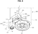
FIG. 6 illustrates an air inflow device equipped in the water tank ofFIG. 4 according to various embodiments of the present disclosure; -
FIG. 7 illustrates the water tank ofFIG. 4 viewed by cutting an air inflow device according to various embodiments of the present disclosure; -
FIG. 8 illustrates the water tank ofFIG. 4 for illustrating operations of the air inflow device and a check valve according to various embodiments of the present disclosure; -
FIG. 9 illustrates the water tank ofFIG. 4 for illustrating a check valve closed when the water tank is turned upside down according to various embodiments of the present disclosure; -
FIG. 10 illustrates a check valve that may close an air tube during replenishment of water to a water tank according to various embodiments of the present disclosure; -
FIG. 11 illustrates a process of water supply from the water tank ofFIG. 4 to a water reservoir according to various embodiments of the present disclosure; -
FIG. 12 illustrates a water tank according to various embodiments of the present disclosure; -
FIG. 13 illustrates a bottom part of the water tank ofFIG. 12 , from which a cap is pulled apart according to various embodiments of the present disclosure; -
FIG. 14 illustrates a cap of the water tank ofFIG. 12 according to various embodiments of the present disclosure; -
FIG. 15 illustrates a cap of the water tank ofFIG. 12 according to various embodiments of the present disclosure; -
FIG. 16 illustrates an open/close unit of the water tank ofFIG. 12 according to various embodiments of the present disclosure; -
FIGS. 17A and17B illustrate a process of water supply from the water tank ofFIG. 12 to a water reservoir according to various embodiments of the present disclosure; -
FIG. 18 illustrates a cap of a water tank according to various embodiments of the present disclosure; -
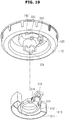
FIG. 19 illustrates a cap and an open/close unit of the water tank ofFIG. 18 , which are pulled apart according to various embodiments of the present disclosure; -
FIGS. 20A and20B illustrate a process of water supply from the water tank ofFIG. 18 to a water reservoir according to various embodiments of the present disclosure; -
FIG. 21 illustrates a water tank with a cap pulled apart according to various embodiments of the present disclosure; -
FIG. 22 is a bottom perspective view of a cap of the water tank ofFIG. 21 according to various embodiments of the present disclosure; -
FIG. 23 illustrates a cap and an open/close unit of the water tank ofFIG. 21 , which are pulled apart according to various embodiments of the present disclosure; and -
FIGS. 24A and24B illustrate a process of water supply from the water tank ofFIG. 21 to a water reservoir according to various embodiments of the present disclosure. - Throughout the drawings, like reference numerals will be understood to refer to like parts, components, and structures.
-
FIGURES 1 through 24 , discussed below, and the various embodiments used to describe the principles of the present disclosure in this patent document are by way of illustration only and should not be construed in any way to limit the scope of the disclosure. Those skilled in the art will understand that the principles of the present disclosure may be implemented in any suitably arranged device. There may be various types of humidifiers, such as heated humidifiers, ultrasonic humidifiers, complex humidifiers having a combination of heated and ultrasonic humidification functions, and evaporative humidifiers naturally evaporating water without use of ultrasounds or heater. - For convenience of explanation, embodiments of an evaporative humidifier will be described. However, the present disclosure is not limited thereto, and it is noted that any of the heated, ultrasound, and complex humidifiers may be used in some other embodiments. Moreover, it is noted that the present disclosure will also be applied in other devices requiring water supply.
- Structure and operation of a humidifier in accordance with embodiments of the present disclosure will now be described with reference to accompanying drawings. As used herein, the singular forms "a", "an" and "the" are intended to include the plural forms as well, unless the context clearly indicates otherwise. For the sake of clarity, the elements of the drawings are drawn with exaggerated forms and sizes.
-
FIG. 1 is a front perspective view of a humidifier, according to an embodiment of the present disclosure,FIG. 2 is a rear perspective view of the humidifier ofFIG. 1 , andFIG. 3 is a front exploded view of the humidifier ofFIG. 1 . - Referring to
FIGS. 1 to 3 , a humidifier 1 in accordance with an embodiment may include amain frame 10 that constitutes an exterior, ablower fan 40 placed inside themain frame 10 for forcedly circulating air, awater reservoir 200 placed inside themain frame 10 for storing water, and ahumidifying element 70 rotatably placed inside themain frame 10 for evaporating water supplied from thewater reservoir 200. - The
main frame 10 may include amain housing 11, afront cover 13 coupled onto a front opening of themain housing 11, a side cover coupled onto a side opening of themain housing 11, and atop cover 12 coupled onto the top of themain housing 11. - An
inlet 11a is formed on the rear side of themain housing 11 to enable dry indoor air to flow to the inside ofmain frame 10, and anoutlet 11b is formed on the top of themain housing 11 to discharge wet air from humidification inside themain frame 10 back into the room. Agrill unit 12a is formed on thetop cover 12 to correspond to theoutlet 11b. - Accordingly, the dry indoor air may flow to the inside of the
main frame 10 through theinlet 11a on the rear side of themain frame 10, be humidified in themain frame 10, and be discharged upward through theoutlet 11b of themain frame 10. - Such forced circulation of the air may be done by the
blower fan 40. Specifically, theblower fan 40 may be a concentric fan, which may be rotated by afirst motor 50 to produce an air current to move the air in the back of themain frame 10 upward of themain frame 10. - A
display unit 20 for displaying various information regarding the humidifier 1, and aninput unit 30 for activating various functions of the humidifier 1 may be mounted on thefront cover 13. - The
humidifying element 70 may be rotatably supported by a supportingframe 90. Thehumidifying element 70 may be rotated by turning force delivered from asecond motor 60. The supportingframe 90 is combined with thewater reservoir 200. Thehumidifying element 70 may be separated from the supportingframe 90. Specifically, after removal of theside cover 14, thewater reservoir 200 and thehumidifying element 70 may be mounted in or separated out of themain frame 10 in the lateral direction. - The humidifier 1 may include a
filter unit 80 for purifying air flowing into themain frame 10, and awater tank 100 for supplying water to thewater reservoir 200. - The
filter unit 80 may include a dust collection filter, deodorization filter, etc. That is, the humidifier 1 may also perform air purification. After removal of thetop cover 12, thefilter unit 80 and thewater tank 100 may be mounted in or separated out of themain frame 10 in the longitudinal direction. - The
water tank 100 may serve to store water necessary for humidification and supply a proper amount of the water to thewater reservoir 200. Thewater tank 100 may be equipped in the humidifier like a cassette unit. - A structure of the water tank will now be described in connection with
FIGS. 4 to 7 .FIG. 4 is a front perspective view of a water tank, according to an embodiment of the present disclosure, andFIG. 5 is an exploded view of a bottom part of the water tank ofFIG. 4 , from which a cap is pulled apart.FIG. 6 is a perspective view of an air inflow device equipped in the water tank ofFIG. 4 , andFIG. 7 is a cross-sectional view of the water tank ofFIG. 4 viewed by cutting the air inflow device. - Referring to
FIGS. 4 and5 , thewater tank 100 may include abody 110, and acap 120 mounted on the bottom of thebody 110. Thecap 120 may include a capairtight member 122 for airtightly close thewater tank 100 while thecap 120 is combined with thebody 110. The capairtight member 122 may be formed of an elastic material, such as rubber. - The
cap 120 may also include awater supply inlet 121 for supplying water stored in thewater tank 100 to thewater reservoir 200. In thewater supply inlet 121, awater supply valve 123 may be arranged to open thewater supply inlet 121 while thewater tank 100 is mounted in the humidifier 1, and to close thewater supply inlet 121 while thewater tank 100 is separated from the humidifier 1. Thewater supply valve 123 may be installed in thewater supply inlet 121 by means of anelastic member 124. At this time, when thewater tank 100 is mounted in thewater reservoir 200 of the humidifier 1, thewater supply valve 123 may be pushed up by a projection (not shown) formed in thewater reservoir 200, to open thewater supply inlet 121. - When a
water level 201 of thewater reservoir 200 decreases due to evaporation of the water by thehumidifying element 70, air flows into thewater tank 100 and pushes the water out of thewater tank 100, achieving water supply. When outside air flows in through thewater supply inlet 121, unusual noise is produced while air bubbles are passing through the water stored in thewater tank 100. - Referring to
FIGS. 4 to 7 , anair inflow device 300 may be equipped on the bottom side of thebody 110 of thewater tank 100, in accordance with an embodiment of the present disclosure. Theair inflow device 300 may introduce anair inflow path 320, which is separate from thewater supply unit 121, to force the air to flow in without passing through the water stored in thewater tank 100. - The
air inflow device 300 may also include an open/close unit 310 to open or close theair inflow path 320. The open/close unit 310 may be contained in ahousing 111 arranged on the bottom side of thebody 110 of thewater tank 100. - The open/
close unit 310 may include afloat 311 that is moved by buoyant force according to thewater level 201 of thewater reservoir 200, and an open/close member 312 for opening or closing theair inflow path 320 according to a height of thefloat 311. The open/close member 312 and thefloat 311 may be hinged through ahinge connector 315. Thehinge connector 315 may combine the open/close member 312 and thefloat 311 by combining a hinge projection formed on the open/close member 312 and a hinge projection receptor hole formed on thefloat 311. - In the
housing 111, anopening 114 to allow water to flow in from thewater reservoir 200 for thefloat 311 to be moved according to changes of thewater level 201 of thewater reservoir 200 may be formed below thefloat 311. Thefloat 311 may be formed in the form of a recess with the bottom face opened to float in water, or in the form of a box with the inside empty and closed. - The open/
close member 312 has one end connected to thefloat 311 through thehinge connector 315, and the other end to be able to open/close theair inflow path 320. The ends of the open/close member 312 moves like a seesaw, in order for the open/close member 312 to open theair inflow path 320 if thefloat 311 falls, and to close theair inflow path 320 if thefloat 311 rises. - The open/
close member 312 may have ahinge projection 314 formed between both ends of the open/close member 312 to enable the ends to move like a seesaw. Thehinge projection 314 of the open/close member 312 may be combined into a hingeprojection receptor hole 112 formed in thehousing 111. - The
air inflow path 320 may include anair inflow pipe 321 formed in thebody 110 of thewater tank 100, and anair tube 322 having one end connected to theair inflow pipe 321 to move the air upward of the inside of thewater tank 100. Anair flow inlet 323, which is opened or closed by the open/close unit 310, is formed on one end of theair inflow pipe 321, and aconnector projection 324 to be connected to theair tube 322 is formed on the other end of theair inflow pipe 321. Specifically, theair flow inlet 323 is formed inside thehousing 111 to be opened/closed by the open/close member 312, and the airtube connector projection 324 is arranged inside thebody 110. - The
air tube 322 is formed of a rubber or plastic material to couple with theconnector projection 324 by fitting theconnector projection 324 into theair tube 322. Theair tube 322 may be formed of a non-flexible material to be able to deliver air from an end where thecap 120 of thewater tank 100 is placed to the other end, or may be formed of a flexible material with sufficient length. - The open/
close unit 310 may include anairtight member 313 formed to airtightly close theair flow path 320, specifically, theair flow inlet 323 of theair inflow pipe 321. Theairtight member 313 may be formed of a material such as rubber. - An air inflow mechanism of the
air inflow device 300, and acheck valve 400 arranged on an end of theair tube 322 will now be described in connection withFIGS. 8 to 11 .FIG. 8 is a cross-sectional view of the water tank ofFIG. 4 for illustrating operations of the air inflow device and a check valve, andFIG. 9 is a cross-sectional view of the water tank ofFIG. 4 for illustrating a check valve closed when the water tank is turned upside down.FIG. 10 is a perspective view of a check valve that may close the air tube during replenishment of water to the water tank.FIG. 11 illustrates a process of water supply from the water tank ofFIG. 4 to the water reservoir. - Referring to
FIGS. 8 to 10 , as described above, an end of theair tube 322 may be coupled with theconnector projection 324 of theair inflow tube 321 inside thebody 110 of thewater tank 100. On the other end of theair tube 322 not coupled with theconnector projection 324, thecheck valve 400 may be arranged to prevent water contained in thewater tank 100 from flowing into theair tube 322. - For example, in a case that the user turns the
water tank 100 upside down with thecap 120 facing up, if thecheck valve 400 is not installed on theair tube 322, water may flow into theair tube 322, and the water flowing into theair tube 322 may be discharged through theair flow inlet 323 when thewater tank 100 is turned upside down again to have thecap 120 face down. Thecheck valve 400 may include installmembers 410 to help thecheck valve 400 to be installed on theair tube 322. Ahook 411 may be formed on the end of the installmember 410 extending from the body of thecheck valve 400 to prevent it from being accidentally separated from theair tube 322. Ahook receiver 322a may be formed on the end of theair tube 322 where thecheck valve 400 is mounted to catch thehook 411. - The
check valve 400 may include arecess 420 formed to close theair tube 322 by buoyant force of the water contained in thewater tank 100 while the water tank is turned upside down with thecap 120 facing up. - Referring to
FIGS. 8 to 11 , thefloat 311 of the open/close unit 310 may be moved up and down according to a height of thesurface 201 of water of thewater reservoir 200. As the float moves up and down, the end of the open/close member 312 coupled with thefloat 311 through thehinge connector 315 may also be moved up and down. Thehinge projection 314 placed between the one end and the other end of the open/close member 312 may be mounted into the hingeprojection receptor hole 112 of thehousing 111. - As one end of the open/
close member 312 is moved up and down by the hinge connection between the open/close member 312 and thehousing 111, the other end of the open/close member 312 may also be moved up and down accordingly. This rotation movement (seesaw movement) of the open/close member 312 may enable the other end of the open/close member 312 to open or close theair flow inlet 323 of theair inflow pipe 321. - The closing
member 313 may be arranged on the other end of the open/close member 312, i.e., the end to open or close theair flow inlet 323 to airtightly close theair flow inlet 323. While thewater tank 100 is mounted in thewater reservoir 200, theair flow inlet 323 is arranged at a location farther away from thewater reservoir 200 than from thewater supply inlet 121 of thewater tank 121. In other words, while thewater tank 100 is mounted in thewater reservoir 200, theair flow inlet 323 is arranged at a location higher than thewater supply inlet 121 of thewater tank 121. - Because the
highest water level 201 of thewater reservoir 200 is below theair flow inlet 323, the water of thewater reservoir 200 may not flow into theair flow inlet 323. Alternatively, even if thehighest water level 201 of thewater reservoir 200 is above theair flow inlet 323, the water of thewater reservoir 200 may not flow into theair flow inlet 323 because the open/close member 312 airtightly closes theair flow inlet 323. - As the water contained in the
water reservoir 200 is used by thehumidifying element 70 for humidification, thewater level 201 of thewater reservoir 200 falls. As thewater level 201 of thewater reservoir 201 falls, thefloat 311 may fall. As thefloat 311 falls, the open/close member 312 turns around thehinge projection 314 to open theair flow inlet 323. - Even if the
highest water level 201 of the water reservoir is above theair flow inlet 323, the water of thewater reservoir 200 may not flow into theair inflow pipe 321 even when theair flow inlet 323 is opened by the open/close member 312 because theair flow inlet 323 is first exposed to air when thewater level 201 falls. - When the open/
close member 312 opens theair flow inlet 323, outside air flows into theair inflow pipe 321, and the air flowing in (A) may be moved upward of the inside of thewater tank 100 along theair tube 322. Due to the air inflow (A), the water stored in thewater tank 100 may be supplied (B) to thewater reservoir 200 through thewater supply inlet 121. - As the water level of the water stored in the
water tank 100 falls (C) due to the water supply (B), thewater level 201 of thewater reservoir 200 rises (D) again. As thewater level 201 of thewater reservoir 200 rises, thefloat 311 rises, causing the open/close member 312 to turn again around thehinge projection 314 to close theair flow inlet 323. When theair flow inlet 323 is closed by the open/close member 312, a vacuum is created in thewater tank 100, and the water supply (B) may be stopped by pressure equalization. - By repeating the water supply process, the
water tank 100 of the humidifier 1 in accordance with an embodiment of the present disclosure may maintain thewater level 201 of thewater reservoir 200 to a constant level while fundamentally preventing noise from being produced by air bubbles flowing into thewater tank 100. - Another embodiment in which an air inflow device of a water tank is installed on the cap of the water tank in accordance with the present disclosure will now be described in connection with
FIGS. 12 to 17 . -
FIG. 12 is a front perspective view of a water tank, according to another embodiment of the present disclosure, andFIG. 13 is a perspective view of a bottom part of the water tank ofFIG. 12 , from which a cap is pulled apart.FIG. 14 is a bottom perspective view of a cap of the water tank ofFIG. 12 ,FIG. 15 is an exploded view of a cap of the water tank ofFIG. 12 , andFIG. 16 is an exploded view of an open/close unit of the water tank ofFIG. 12 .FIGS. 17A and17B illustrate a process of water supply from the water tank ofFIG. 12 to a water reservoir. Referring toFIG. 12 , theair inflow device 300 is not installed in the body of thewater tank 100, but in thecap 120 of thewater tank 100. Accordingly, unlike the water tank shown inFIG. 4 , no housing is formed in thebody 110 of thewater tank 100 to house the open/close unit 310. Referring toFIGS. 13 to 16 , thecap 120 of thewater tank 100 ofFIG. 14 has the same basic structure as that of the cap of the water tank ofFIG. 4 . Thecap 120 may include the capairtight member 122 for airtightly close thewater tank 100 while thecap 120 is combined with thebody 110. The capairtight member 122 may be formed of an elastic material, such as rubber. Thecap 120 may also include thewater supply inlet 121 for supplying water stored in thewater tank 100 to thewater reservoir 200. In thewater supply inlet 121, thewater supply valve 123 may be arranged to open thewater supply inlet 121 while thewater tank 100 is mounted in the humidifier 1, and to close thewater supply inlet 121 while thewater tank 100 is separated from the humidifier 1. Thewater supply valve 123 may be installed in thewater supply inlet 121 by means of theelastic member 124. At this time, when thewater tank 100 is mounted in thewater reservoir 200 of the humidifier 1, thewater supply valve 123 may be pushed up by a projection (not shown) formed in thewater reservoir 200, to open thewater supply inlet 121. Theair inflow device 300 installed in thecap 120 may include theair inflow path 320, and the open/close unit 310 to open or close theair inflow path 320. The open/close unit 310 may include thefloat 311 that is moved by buoyant force according to thewater level 201 of thewater reservoir 200, and the open/close member 312 for opening or closing theair inflow path 320 according to a height of thefloat 311. The open/close member 312 and thefloat 311 may be hinged through thehinge connector 315. Thehinge connector 315 may combine the open/close member 312 and thefloat 311 by combining ahinge projection 315a formed on the open/close member 312 and a hingeprojection receptor hole 315b formed on thefloat 311. - The
float 311 may be formed in the form of a recess with the bottom face opened to float in water, or as shown inFIGS. 12 to 17 , in the form of a box with the inside empty and closed. The open/close member 312 has one end connected to thefloat 311 through thehinge connector 315, and the other end to open or close theair inflow path 320. The ends of the open/close member 312 moves like a seesaw, in order for the open/close member 312 to open theair inflow path 320 if thefloat 311 falls, and to close theair inflow path 320 if thefloat 311 rises. - The open/
close member 312 may have thehinge projection 314 formed between both ends of the open/close member 312 to enable the ends to move like a seesaw. Thehinge projection 314 of the open/close member 312 may be combined into the hingeprojection receptor hole 112 formed in thecap 120. - The
air inflow path 320 may include theair inflow pipe 321 formed in thecap 120 of thewater tank 100, and theair tube 322 having one end connected to theair inflow pipe 321 to move the air upward of the inside of thewater tank 100. Theair flow inlet 323, which is opened or closed by the open/close unit 310, is formed on one end of theair inflow pipe 321, and theconnection projection 324 to be connected to theair tube 322 is formed on the other end of theair inflow pipe 321. Specifically, theair flow inlet 323 is formed outside thewater tank 100 if thecap 120 is mounted in thebody 110, to be opened or closed by the open/close member 312, and the airtube connector projection 324 is arranged inside thewater tank 100. - The
air tube 322 is formed of a rubber or plastic material to couple with theconnector projection 324 by fitting theconnector projection 324 into theair tube 322. Theair tube 322 may be formed of a non-flexible material to be able to deliver air from an end where thecap 120 is placed to the other end, or may be formed of a flexible material with sufficient length. - Although not shown, on an end of the
air tube 322 not coupled with theconnector projection 324, thecheck valve 400 may be arranged to prevent the water contained in thewater tank 100 from flowing into theair tube 322. - The open/
close unit 310 may include theairtight member 313 formed to airtightly close theair flow path 320, specifically, theair flow inlet 323 of theair inflow pipe 321. Theairtight member 313 may be formed of a material such as rubber. - Referring to
FIG. 17A andFIG. 17B , thefloat 311 of the open/close unit 310 may be moved up and down according to the height of thesurface 201 of water of thewater reservoir 200. As thefloat 311 moves up and down, the end of the open/close member 312 coupled with thefloat 311 at thehinge connector 315 may also be moved up and down. Thehinge projection 314 placed between the one end and the other end of the open/close member 312 may be mounted into the hingeprojection receptor hole 112 formed in thecap 120. - As one end of the open/
close member 312 is moved up and down by the hinge connection between the open/close member 312 and thecap 120, the other end of the open/close member 312 may also be moved up and down accordingly. This rotation movement (seesaw movement) of the open/close member 312 may enable the other end of the open/close member 312 to open or close theair flow inlet 323 of theair inflow pipe 321. - The
airtight member 313 may be arranged on the other end of the open/close member 312, i.e., the end to open or close theair flow inlet 323 to airtightly close theair flow inlet 323. While thewater tank 100 is mounted in thewater reservoir 200, theair flow inlet 323 is arranged at a location farther away from thewater reservoir 200 than from thewater supply inlet 121 of thewater tank 121. In other words, while thewater tank 100 is mounted in thewater reservoir 200, theair flow inlet 323 is located higher than thewater supply inlet 121 of thewater tank 121. - Because the
highest water level 201 of thewater reservoir 200 is below theair flow inlet 323, the water of thewater reservoir 200 may not flow into theair flow inlet 323. Alternatively, even if thehighest water level 201 of thewater reservoir 200 is above theair flow inlet 323, the water of thewater reservoir 200 may not flow into theair flow inlet 323 because the open/close member 312 airtightly closes theair flow inlet 323. - Referring to
FIG. 17A , as the water contained in thewater reservoir 200 is used by thehumidifying element 70 for humidification, thewater level 201 of thewater reservoir 200 falls. As thewater level 201 of thewater reservoir 201 falls, thefloat 311 may fall. As thefloat 311 falls, the open/close member 312 turns around thehinge projection 314 to open theair flow inlet 323. - Even if the
highest water level 201 of the water reservoir is above theair flow inlet 323, the water of thewater reservoir 200 may not flow into theair inflow pipe 321 even when theair flow inlet 323 is opened by the open/close member 312 because theair flow inlet 323 is first exposed to air when thewater level 201 falls. - When the open/
close member 312 opens theair flow inlet 323, outside air flows into theair inflow pipe 321, and the air flowing in (A) may be moved upward of the inside of thewater tank 100 along theair tube 322. Due to the air inflow (A), the water stored in thewater tank 100 may be supplied (B) to thewater reservoir 200 through thewater supply inlet 121. - Referring to
FIG. 17B , as thewater level 201 rises due to the water supply (B), thefloat 311 rises, causing the open/close member 312 to turn again around thehinge projection 314 to close theair flow inlet 323. When theair flow inlet 323 is closed by the open/close member 312, a vacuum is created in thewater tank 100, and the water supply (B) may be stopped by pressure equalization. - By repeating the water supply process, the
water tank 100 of the humidifier 1 in accordance with an embodiment of the present disclosure may maintain thewater level 201 of thewater reservoir 200 to a constant level while fundamentally preventing noise from being produced by air bubbles flowing into thewater tank 100. -
FIG. 18 is a bottom perspective view of a cap of a water tank, according to another embodiment of the present disclosure, andFIG. 19 is a perspective view of a cap and an open/close unit of the water tank ofFIG. 18 , which are pulled apart.FIGS. 20A and20B illustrate a process of water supply from the water tank ofFIG. 19 to a water reservoir. - A basic structure of the
cap 120 of thewater tank 100 ofFIG. 18 is the same as that of the cap of the water tank ofFIG. 12 . - Description of the same parts of the structure will be omitted herein.
- The
float 311 may be formed with the inside empty or closed as shown inFIGS. 12 to 17 in order to float in water, or may be formed in the form of a recess with the bottom face opened as shown inFIGS. 18 to 20 . - Unlike the open/close unit of the air inflow device installed in the cap of the water tank of
FIG. 12 , the open/close unit 310 of theair inflow device 300 installed in thecap 120 of thewater tank 100 ofFIG. 18 may be formed to have thefloat 311 and the open/close member 312 integrated in one unit. The integration of the open/close unit 310 and thefloat 311 in one unit may reduce the number of constituent parts and simplify the structure. - The open/
close member 312 has one end integrally connected to thefloat 311, and the other end to be able to open or close theair inflow path 320. The ends of the open/close member 312 moves like a seesaw, in order for the open/close member 312 to open theair inflow path 320 if thefloat 311 falls, and to close theair inflow path 320 if thefloat 311 rises. - The open/
close member 312 may have thehinge projection 314 formed between both ends of the open/close member 312 to enable the ends to move like a seesaw. Thehinge projection 314 of the open/close member 312 may be combined into the hingeprojection receptor hole 112 formed in thecap 120. - Referring to
FIGS. 20A and20B , thefloat 311 of the open/close unit 310 may be moved up and down according to the height of thesurface 201 of water of thewater reservoir 200. As thefloat 311 connected to one end of the open/close member 312 moves up and down, the other end of the open/close member 312 may be moved up and down. This rotation movement (seesaw movement) of the open/close member 312 may enable the other end of the open/close member 312 to open or close theair flow inlet 323 of theair inflow pipe 321. - Unlike the float of the open/close unit of the water tank shown in
FIGS. 17A and17B moving up and down at a level with the surface of water of the water reservoir, thefloat 311 of the open/close unit 310 ofFIGS. 20A and20B may turn around thehinge projection 314. -
FIG. 21 is a perspective view of a water tank with a cap pulled apart, according to another embodiment of the present disclosure,FIG. 22 is a bottom perspective view of a cap of the water tank ofFIG. 21 , andFIG. 23 is a perspective view of a cap and an open/close unit of the water tank ofFIG. 21 , which are pulled apart.FIGS. 24A and24B illustrate a process of water supply from the water tank ofFIG. 21 to a water reservoir. - A basic structure of the
cap 120 of thewater tank 100 ofFIG. 21 is the same as that of the cap of the water tank ofFIG. 12 . Description of the same parts of the structure will be omitted herein. - Referring to
FIGS. 21 to 23 , theair inflow device 300 installed in thecap 120 may include theair inflow path 320, and thefloat 311 to open or close theair inflow path 320. That is, the open/close unit may be configured only with thefloat 311. - The
float 311 may be moved by buoyant force according to thewater level 201 of thewater reservoir 200, and theair inflow path 320 may be opened or closed according to the height of thefloat 311. The open/close member 312 may open theair inflow path 320 if thefloat 311 falls, and may close theair inflow path 320 if thefloat 311 rises. - The
float 311 may be formed with the inside empty or closed in order to float in water, or may be formed in the form of a recess with the bottom face opened as shown inFIGS. 21 to 24 . Thecap 120 may include ananti-separation structure 125 to prevent accidental separation of thefloat 311. Thefloat 311 may have the form similar to a tire, which encloses thewater supply inlet 121, and may be mounted in thecap 120 to enclose thewater supply inlet 121. Theanti-separation structure 125 may be formed at the end of thewater supply inlet 121. - The
air inflow path 320 may include theair inflow pipe 321 formed in thecap 120 of thewater tank 100, and theair tube 322 having one end connected to theair inflow pipe 321 to move the air upward of the inside of the water tank. Theair flow inlet 323, which is opened or closed by thefloat 311, is formed on one end of theair inflow pipe 321, and theconnector projection 324 to be connected to theair tube 322 is formed on the other end of theair inflow pipe 321. Specifically, theair flow inlet 323 is formed outside thewater tank 100 if thecap 120 is mounted in thebody 110, to be opened or closed by the open/close member 311, and the airtube connector projection 324 is arranged inside thewater tank 100. - The
float 311 may include theairtight member 313 formed to airtightly close theair flow path 320, specifically, theair flow inlet 323 of theair inflow pipe 321. Theairtight member 313 may be formed of a material such as rubber. - The
cap 120 may include a supportingprotrusion 126 formed to facilitate thefloat 311 to open or close theair flow inlet 323 by remaining level when thefloat 311 rises. - Referring to
FIGS. 24A and24B , thefloat 311 may be moved up and down according to the height of thesurface 201 of water of thewater reservoir 200. If thewater level 201 of thewater reservoir 200 increases, thefloat 311 may rise until theair flow inlet 323 and the supportingprotrusion 126 come into contact with each other, to close theair flow inlet 323. If thewater level 201 of thewater reservoir 200 decreases, thefloat 311 falls until coming into contact with theanti-separation structure 125, to open theair flow inlet 323. - A home appliance equipped with the humidifier or water tank in accordance with the embodiments of the present disclosure may maintain a silent state of operation in an environment requiring low noise, and automatically control the water level by means of buoyant force without use of an electric valve unit, thereby reducing the manufacturing costs and achieving structural improvement.
- In the meantime, even if the open/close unit may not be able to close the air inflow path due to a malfunction of the air inflow device of the home appliance equipped with the humidifier or water tank in accordance with the embodiments of the present disclosure, when the air flow inlet of the air inflow path is closed as the water level of the water reservoir increases, air inflow is blocked and water supply is stopped, thereby enabling normal water supply without overflowing of water from the water reservoir.
- According to embodiments of the present disclosure, an air inflow path introduced separately from a water supply inlet in a water tank of a humidifier prevents noise generation due to air bubbles while water is supplied to a water reservoir from the water tank.
- Furthermore, the air inflow path may be blocked to prevent water from flowing into the air inflow path during replenishment of water to the water tank of the humidifier.
- Although the present disclosure has been described with an exemplary embodiment, various changes and modifications may be suggested to one skilled in the art. It is intended that the present disclosure encompass such changes and modifications as fall within the scope of the appended claims.
Claims (10)
- A home appliance (1) comprising:a water tank (100) comprising an air inflow device (300); anda water reservoir (200) configured to contain water flowing in from the water tank (100),wherein the air inflow device (300) comprises an air inflow path (320) separate from the water flowing in from the water tank (100) into the water reservoir (200) and an open/close unit (310) configured to open or close the air inflow path (320), characterized in that the open/close unit (310) comprises:a float (311) configured to move according to a water level of the water reservoir (200); andan open/close member (312) configured to open or close the air inflow path (320) according to a height of the float (311), wherein the open/close member (312) is further configured to:open the air inflow path (320) if the float (311) falls, andclose the air inflow path (320) if the float (311) rises.
- The home appliance (1) of claim 1, further comprising a humidifying element (70) configured to perform humidification with supplied water contained in the water reservoir (200).
- The home appliance (1) of any one of the preceding claims, wherein the air inflow path (320) comprises:an air inflow pipe (321) configured to be opened or closed by the open/close unit (310); andan air tube (322) connected to the air inflow pipe (321).
- The home appliance (1) of any one of the preceding claims, wherein the open/close unit (310) comprises an airtight member (313) formed to airtightly close the air inflow path (320).
- The home appliance (1) of any one of the preceding claims, wherein the air inflow device (300) comprises a check valve (400) configured to prevent water from flowing into the air inflow path (320) from the water tank (100) during replenishment of water to the water tank (100).
- The home appliance (1) of claim 5, wherein the check valve (400) comprises a recess (420) formed to receive buoyant force.
- The home appliance (1) according to any one of the preceding claims,
wherein the water tank (100) comprises a body (110) and a cap (120);
wherein the cap (120) of the water tank (100) is equipped with a water supply inlet (121) configured to supply water to the water reservoir (200), and
wherein the body (110) of the water tank is equipped with the air inflow path (320) and the open/close unit (310). - The home appliance (1) of any one of the preceding claims including claims 1 and 3,
wherein the air inflow pipe (321) is configured to be opened or closed by the open/close member (312). - The home appliance (1) of any one of the other preceding claims including claims 3 and 4, wherein the airtight member (313) is configured to airtightly close an air flow inlet (323) of an air inflow pipe (321).
- The home appliance (1) of claim 9, wherein the air flow inlet (323) of the air inflow pipe (321) is located farther away from the water reservoir (200) than from the water supply inlet (121),
wherein the air flow inlet (323) is exposed to air if a water level of the water reservoir (200) decreases, and the open/close member (312) is configured to open the air flow inlet (323) as the float (311) falls, and
wherein the float (311) is configured to rise again and enable the open/close member (312) to close the air flow inlet (323) again, if water of the water tank (100) flows into the water reservoir (200) through the water supply inlet (121).
Applications Claiming Priority (1)
| Application Number | Priority Date | Filing Date | Title |
|---|---|---|---|
| KR1020150053883A KR102466276B1 (en) | 2015-04-16 | 2015-04-16 | Humidifier and domestic appliance |
Publications (2)
| Publication Number | Publication Date |
|---|---|
| EP3081872A1 EP3081872A1 (en) | 2016-10-19 |
| EP3081872B1 true EP3081872B1 (en) | 2020-06-17 |
Family
ID=55527408
Family Applications (1)
| Application Number | Title | Priority Date | Filing Date |
|---|---|---|---|
| EP16159876.8A Active EP3081872B1 (en) | 2015-04-16 | 2016-03-11 | Home appliance |
Country Status (6)
| Country | Link |
|---|---|
| US (2) | US10436466B2 (en) |
| EP (1) | EP3081872B1 (en) |
| KR (1) | KR102466276B1 (en) |
| CN (2) | CN107810370B (en) |
| AU (1) | AU2016249637B2 (en) |
| WO (1) | WO2016167465A1 (en) |
Families Citing this family (14)
| Publication number | Priority date | Publication date | Assignee | Title |
|---|---|---|---|---|
| US11549699B2 (en) * | 2017-10-03 | 2023-01-10 | Vornado Air, Llc | Portable humidifier |
| JP1631156S (en) * | 2018-05-10 | 2019-05-13 | ||
| CN108825803A (en) * | 2018-08-27 | 2018-11-16 | 珠海格力电器股份有限公司 | It is discharged valve arrangement and the humidifier including it |
| CN109373443B (en) * | 2018-10-18 | 2021-11-19 | 广东美的制冷设备有限公司 | Water tank assembly of air conditioner and air conditioner indoor unit |
| CN109708230B (en) * | 2018-12-19 | 2021-08-31 | 浙江黄岩康宝利清香剂厂 | Gas humidifying device |
| GB201900018D0 (en) * | 2019-01-02 | 2019-02-13 | Dyson Technology Ltd | Air treatment apparatus |
| KR102340052B1 (en) * | 2019-01-03 | 2021-12-16 | 코웨이 주식회사 | Humidifier |
| CN110186139A (en) * | 2019-05-29 | 2019-08-30 | 深圳市晨北科技有限公司 | A kind of water-tight device and humidifier |
| CN110274337A (en) * | 2019-06-14 | 2019-09-24 | 深圳市晨北科技有限公司 | A kind of humidifier |
| KR20200144003A (en) * | 2019-06-17 | 2020-12-28 | 코웨이 주식회사 | Air Cleaner Having Humidifying Function |
| JP1686298S (en) * | 2019-12-23 | 2021-05-31 | ||
| KR20210101899A (en) * | 2020-02-11 | 2021-08-19 | 삼성전자주식회사 | Humidification apparatus |
| JP1705360S (en) * | 2020-10-15 | 2022-01-19 | Air cleaner | |
| WO2023281292A1 (en) * | 2021-07-04 | 2023-01-12 | Okhotnikov Kirill | Noise reducing device for apparatus to be filled with water |
Citations (4)
| Publication number | Priority date | Publication date | Assignee | Title |
|---|---|---|---|---|
| US4765327A (en) * | 1986-12-19 | 1988-08-23 | Respiratory Care, Inc. | Cartridge humidifier vent valve |
| JP3110210U (en) * | 2005-01-14 | 2005-06-16 | 有限会社アイ・シー・アイデザイン研究所 | humidifier |
| KR20080014165A (en) * | 2006-08-10 | 2008-02-14 | 위니아만도 주식회사 | Humidifier and supplement water bucket for the same |
| JP2010196933A (en) * | 2009-02-24 | 2010-09-09 | Tiger Vacuum Bottle Co Ltd | Water supply device |
Family Cites Families (28)
| Publication number | Priority date | Publication date | Assignee | Title |
|---|---|---|---|---|
| US4500480A (en) * | 1982-08-23 | 1985-02-19 | Respiratory Care, Inc. | Pediatric cartridge humidifier |
| US4489744A (en) * | 1982-09-27 | 1984-12-25 | The United States Of America As Represented By The United States Department Of Energy | Liquid blocking check valve |
| US5431290A (en) * | 1992-03-24 | 1995-07-11 | Vinciguerra; Mark T. | Baby bottle for improved flow |
| JP3110210B2 (en) * | 1993-06-24 | 2000-11-20 | 日本電気株式会社 | Data analysis support method |
| KR960001651A (en) | 1994-06-22 | 1996-01-25 | 이헌조 | Method and device for removing abnormal noise of humidifier |
| US5547615A (en) * | 1995-05-10 | 1996-08-20 | Duracraft Corporation | Portable humidifier with bacteriastat dispenser |
| US6248155B1 (en) * | 1999-08-13 | 2001-06-19 | Bemis Manufacturing Company | Combination humidifier and air purifier |
| US20030016952A1 (en) * | 2001-07-10 | 2003-01-23 | Elphee David Andrew | Low-maintenance humidifier |
| JP2003240282A (en) * | 2002-02-14 | 2003-08-27 | Kunio Takagi | Non-contact and pipe type water discharge valve device |
| DE10234811C1 (en) * | 2002-07-31 | 2003-11-27 | Draeger Medical Ag | Humidification system for gases respired by patient, includes water reservoir system isolated from surroundings and connected by feed- and vent lines to water boiler |
| US6988497B2 (en) * | 2002-09-18 | 2006-01-24 | Medex Cardio-Pulmonary, Inc. | Apparatus for equalizing air pressure in air respiratory system |
| DE10251134A1 (en) * | 2002-10-31 | 2004-05-19 | GRÜNDLER GmbH | Respirator and method |
| US7228859B2 (en) * | 2004-06-29 | 2007-06-12 | Teleflex Medical Incorporated | Pressure venting circuit for respiratory humidification apparatus |
| US7722016B2 (en) * | 2006-08-31 | 2010-05-25 | Medex Cardio-Pulmonary, Inc. | Float for humidification chamber |
| JP4726760B2 (en) | 2006-10-06 | 2011-07-20 | 三菱電機株式会社 | Humidifiers and equipment |
| US20080093750A1 (en) * | 2006-10-18 | 2008-04-24 | Zhijing Wang | Dual inlet water tank for a humidifier |
| DE102009011137A1 (en) * | 2009-03-03 | 2010-09-09 | Seleon Gmbh | Evaporation chamber, intermediate chamber and process |
| US8931762B2 (en) * | 2010-12-23 | 2015-01-13 | Lg Electronics Inc. | Air conditioner |
| JP2013002797A (en) * | 2011-06-22 | 2013-01-07 | Panasonic Corp | Humidifier |
| KR101163721B1 (en) * | 2011-11-09 | 2012-07-09 | 와토스코리아 주식회사 | Switching devices for rim side water in low tank toilet |
| US10213573B2 (en) * | 2011-12-22 | 2019-02-26 | Resmed Limited | Humidifiers for respiratory apparatus |
| US8701701B2 (en) * | 2012-09-25 | 2014-04-22 | Chin-Cheng Huang | Float switch of a humidifier |
| US9360227B2 (en) * | 2013-03-15 | 2016-06-07 | Helen Of Troy Limited | Removable top fill tank |
| KR102125718B1 (en) * | 2013-06-05 | 2020-06-23 | 삼성전자주식회사 | Water filter for humidifier |
| CN204202078U (en) * | 2014-10-22 | 2015-03-11 | 漳州蒙发利实业有限公司 | A kind of air humidifier |
| CN204202075U (en) * | 2014-10-22 | 2015-03-11 | 厦门蒙发利健康科技有限公司 | A kind of mute type humidifier |
| JP5915725B1 (en) * | 2014-12-26 | 2016-05-11 | ダイキン工業株式会社 | Water treatment equipment |
| US10168064B1 (en) * | 2018-07-13 | 2019-01-01 | Zhongshan Titan Arts & Crafts Co., Ltd. | Ultrasonic humidifier |
-
2015
- 2015-04-16 KR KR1020150053883A patent/KR102466276B1/en active IP Right Grant
-
2016
- 2016-02-23 AU AU2016249637A patent/AU2016249637B2/en not_active Ceased
- 2016-02-23 CN CN201680035070.8A patent/CN107810370B/en active Active
- 2016-02-23 WO PCT/KR2016/001733 patent/WO2016167465A1/en active Application Filing
- 2016-02-23 CN CN202010181188.XA patent/CN111238020B/en active Active
- 2016-03-11 EP EP16159876.8A patent/EP3081872B1/en active Active
- 2016-03-25 US US15/081,658 patent/US10436466B2/en active Active
-
2019
- 2019-08-30 US US16/557,829 patent/US10808952B2/en active Active
Patent Citations (4)
| Publication number | Priority date | Publication date | Assignee | Title |
|---|---|---|---|---|
| US4765327A (en) * | 1986-12-19 | 1988-08-23 | Respiratory Care, Inc. | Cartridge humidifier vent valve |
| JP3110210U (en) * | 2005-01-14 | 2005-06-16 | 有限会社アイ・シー・アイデザイン研究所 | humidifier |
| KR20080014165A (en) * | 2006-08-10 | 2008-02-14 | 위니아만도 주식회사 | Humidifier and supplement water bucket for the same |
| JP2010196933A (en) * | 2009-02-24 | 2010-09-09 | Tiger Vacuum Bottle Co Ltd | Water supply device |
Also Published As
| Publication number | Publication date |
|---|---|
| US10808952B2 (en) | 2020-10-20 |
| AU2016249637B2 (en) | 2020-11-12 |
| CN107810370A (en) | 2018-03-16 |
| WO2016167465A1 (en) | 2016-10-20 |
| US20190383503A1 (en) | 2019-12-19 |
| CN111238020A (en) | 2020-06-05 |
| KR102466276B1 (en) | 2022-11-11 |
| AU2016249637A1 (en) | 2017-11-02 |
| CN111238020B (en) | 2021-08-17 |
| US10436466B2 (en) | 2019-10-08 |
| CN107810370B (en) | 2020-04-10 |
| EP3081872A1 (en) | 2016-10-19 |
| KR20160123624A (en) | 2016-10-26 |
| US20160305674A1 (en) | 2016-10-20 |
Similar Documents
| Publication | Publication Date | Title |
|---|---|---|
| EP3081872B1 (en) | Home appliance | |
| US9423141B2 (en) | Console humidifier | |
| JP6002696B2 (en) | Humidifier with liquid intrusion protection | |
| KR102340052B1 (en) | Humidifier | |
| US10228150B2 (en) | Humidifying apparatus | |
| US20230093557A1 (en) | Humidifier | |
| CN101749821A (en) | Humidifier | |
| KR102046476B1 (en) | Humidification apparatus capable of preventing water leak | |
| JP2008039326A (en) | Humidification apparatus | |
| JP2010019445A (en) | Humidifier | |
| JP6633015B2 (en) | Humidifier | |
| WO2020207283A1 (en) | Steam generation device and air conditioning device | |
| JP4648256B2 (en) | Water supply equipment | |
| KR102237457B1 (en) | Water supply type air washer | |
| JP2008020115A (en) | Water supply device | |
| CN111397061A (en) | Air treatment device | |
| JP2010164265A (en) | Humidifier | |
| KR102360877B1 (en) | Humidifier and domestic appliance | |
| JP6912424B2 (en) | Humidifier | |
| JPWO2015182738A1 (en) | Air conditioner | |
| CN213747007U (en) | Humidifying device of air treatment device, air treatment device and air conditioner indoor unit | |
| JP7348537B2 (en) | humidifier | |
| JP2010196933A (en) | Water supply device | |
| KR101710166B1 (en) | wall-mounted type humidifier | |
| KR20080004003U (en) | Humidifier |
Legal Events
| Date | Code | Title | Description |
|---|---|---|---|
| PUAI | Public reference made under article 153(3) epc to a published international application that has entered the european phase |
Free format text: ORIGINAL CODE: 0009012 |
|
| AK | Designated contracting states |
Kind code of ref document: A1 Designated state(s): AL AT BE BG CH CY CZ DE DK EE ES FI FR GB GR HR HU IE IS IT LI LT LU LV MC MK MT NL NO PL PT RO RS SE SI SK SM TR |
|
| AX | Request for extension of the european patent |
Extension state: BA ME |
|
| STAA | Information on the status of an ep patent application or granted ep patent |
Free format text: STATUS: REQUEST FOR EXAMINATION WAS MADE |
|
| 17P | Request for examination filed |
Effective date: 20161222 |
|
| RBV | Designated contracting states (corrected) |
Designated state(s): AL AT BE BG CH CY CZ DE DK EE ES FI FR GB GR HR HU IE IS IT LI LT LU LV MC MK MT NL NO PL PT RO RS SE SI SK SM TR |
|
| STAA | Information on the status of an ep patent application or granted ep patent |
Free format text: STATUS: EXAMINATION IS IN PROGRESS |
|
| 17Q | First examination report despatched |
Effective date: 20170830 |
|
| GRAP | Despatch of communication of intention to grant a patent |
Free format text: ORIGINAL CODE: EPIDOSNIGR1 |
|
| STAA | Information on the status of an ep patent application or granted ep patent |
Free format text: STATUS: GRANT OF PATENT IS INTENDED |
|
| RIC1 | Information provided on ipc code assigned before grant |
Ipc: F24F 13/24 20060101ALI20200129BHEP Ipc: F24F 6/00 20060101AFI20200129BHEP Ipc: F24F 6/16 20060101ALI20200129BHEP Ipc: F24F 11/74 20180101ALI20200129BHEP |
|
| INTG | Intention to grant announced |
Effective date: 20200217 |
|
| GRAS | Grant fee paid |
Free format text: ORIGINAL CODE: EPIDOSNIGR3 |
|
| GRAA | (expected) grant |
Free format text: ORIGINAL CODE: 0009210 |
|
| STAA | Information on the status of an ep patent application or granted ep patent |
Free format text: STATUS: THE PATENT HAS BEEN GRANTED |
|
| AK | Designated contracting states |
Kind code of ref document: B1 Designated state(s): AL AT BE BG CH CY CZ DE DK EE ES FI FR GB GR HR HU IE IS IT LI LT LU LV MC MK MT NL NO PL PT RO RS SE SI SK SM TR |
|
| REG | Reference to a national code |
Ref country code: GB Ref legal event code: FG4D |
|
| REG | Reference to a national code |
Ref country code: CH Ref legal event code: EP |
|
| REG | Reference to a national code |
Ref country code: IE Ref legal event code: FG4D |
|
| REG | Reference to a national code |
Ref country code: DE Ref legal event code: R096 Ref document number: 602016038072 Country of ref document: DE |
|
| REG | Reference to a national code |
Ref country code: AT Ref legal event code: REF Ref document number: 1281779 Country of ref document: AT Kind code of ref document: T Effective date: 20200715 |
|
| PG25 | Lapsed in a contracting state [announced via postgrant information from national office to epo] |
Ref country code: FI Free format text: LAPSE BECAUSE OF FAILURE TO SUBMIT A TRANSLATION OF THE DESCRIPTION OR TO PAY THE FEE WITHIN THE PRESCRIBED TIME-LIMIT Effective date: 20200617 Ref country code: NO Free format text: LAPSE BECAUSE OF FAILURE TO SUBMIT A TRANSLATION OF THE DESCRIPTION OR TO PAY THE FEE WITHIN THE PRESCRIBED TIME-LIMIT Effective date: 20200917 Ref country code: GR Free format text: LAPSE BECAUSE OF FAILURE TO SUBMIT A TRANSLATION OF THE DESCRIPTION OR TO PAY THE FEE WITHIN THE PRESCRIBED TIME-LIMIT Effective date: 20200918 Ref country code: SE Free format text: LAPSE BECAUSE OF FAILURE TO SUBMIT A TRANSLATION OF THE DESCRIPTION OR TO PAY THE FEE WITHIN THE PRESCRIBED TIME-LIMIT Effective date: 20200617 Ref country code: LT Free format text: LAPSE BECAUSE OF FAILURE TO SUBMIT A TRANSLATION OF THE DESCRIPTION OR TO PAY THE FEE WITHIN THE PRESCRIBED TIME-LIMIT Effective date: 20200617 |
|
| REG | Reference to a national code |
Ref country code: LT Ref legal event code: MG4D |
|
| REG | Reference to a national code |
Ref country code: NL Ref legal event code: MP Effective date: 20200617 |
|
| PG25 | Lapsed in a contracting state [announced via postgrant information from national office to epo] |
Ref country code: RS Free format text: LAPSE BECAUSE OF FAILURE TO SUBMIT A TRANSLATION OF THE DESCRIPTION OR TO PAY THE FEE WITHIN THE PRESCRIBED TIME-LIMIT Effective date: 20200617 Ref country code: BG Free format text: LAPSE BECAUSE OF FAILURE TO SUBMIT A TRANSLATION OF THE DESCRIPTION OR TO PAY THE FEE WITHIN THE PRESCRIBED TIME-LIMIT Effective date: 20200917 Ref country code: LV Free format text: LAPSE BECAUSE OF FAILURE TO SUBMIT A TRANSLATION OF THE DESCRIPTION OR TO PAY THE FEE WITHIN THE PRESCRIBED TIME-LIMIT Effective date: 20200617 Ref country code: HR Free format text: LAPSE BECAUSE OF FAILURE TO SUBMIT A TRANSLATION OF THE DESCRIPTION OR TO PAY THE FEE WITHIN THE PRESCRIBED TIME-LIMIT Effective date: 20200617 |
|
| REG | Reference to a national code |
Ref country code: AT Ref legal event code: MK05 Ref document number: 1281779 Country of ref document: AT Kind code of ref document: T Effective date: 20200617 |
|
| PG25 | Lapsed in a contracting state [announced via postgrant information from national office to epo] |
Ref country code: AL Free format text: LAPSE BECAUSE OF FAILURE TO SUBMIT A TRANSLATION OF THE DESCRIPTION OR TO PAY THE FEE WITHIN THE PRESCRIBED TIME-LIMIT Effective date: 20200617 Ref country code: NL Free format text: LAPSE BECAUSE OF FAILURE TO SUBMIT A TRANSLATION OF THE DESCRIPTION OR TO PAY THE FEE WITHIN THE PRESCRIBED TIME-LIMIT Effective date: 20200617 |
|
| PG25 | Lapsed in a contracting state [announced via postgrant information from national office to epo] |
Ref country code: ES Free format text: LAPSE BECAUSE OF FAILURE TO SUBMIT A TRANSLATION OF THE DESCRIPTION OR TO PAY THE FEE WITHIN THE PRESCRIBED TIME-LIMIT Effective date: 20200617 Ref country code: EE Free format text: LAPSE BECAUSE OF FAILURE TO SUBMIT A TRANSLATION OF THE DESCRIPTION OR TO PAY THE FEE WITHIN THE PRESCRIBED TIME-LIMIT Effective date: 20200617 Ref country code: AT Free format text: LAPSE BECAUSE OF FAILURE TO SUBMIT A TRANSLATION OF THE DESCRIPTION OR TO PAY THE FEE WITHIN THE PRESCRIBED TIME-LIMIT Effective date: 20200617 Ref country code: IT Free format text: LAPSE BECAUSE OF FAILURE TO SUBMIT A TRANSLATION OF THE DESCRIPTION OR TO PAY THE FEE WITHIN THE PRESCRIBED TIME-LIMIT Effective date: 20200617 Ref country code: SM Free format text: LAPSE BECAUSE OF FAILURE TO SUBMIT A TRANSLATION OF THE DESCRIPTION OR TO PAY THE FEE WITHIN THE PRESCRIBED TIME-LIMIT Effective date: 20200617 Ref country code: CZ Free format text: LAPSE BECAUSE OF FAILURE TO SUBMIT A TRANSLATION OF THE DESCRIPTION OR TO PAY THE FEE WITHIN THE PRESCRIBED TIME-LIMIT Effective date: 20200617 Ref country code: RO Free format text: LAPSE BECAUSE OF FAILURE TO SUBMIT A TRANSLATION OF THE DESCRIPTION OR TO PAY THE FEE WITHIN THE PRESCRIBED TIME-LIMIT Effective date: 20200617 Ref country code: PT Free format text: LAPSE BECAUSE OF FAILURE TO SUBMIT A TRANSLATION OF THE DESCRIPTION OR TO PAY THE FEE WITHIN THE PRESCRIBED TIME-LIMIT Effective date: 20201019 |
|
| PG25 | Lapsed in a contracting state [announced via postgrant information from national office to epo] |
Ref country code: PL Free format text: LAPSE BECAUSE OF FAILURE TO SUBMIT A TRANSLATION OF THE DESCRIPTION OR TO PAY THE FEE WITHIN THE PRESCRIBED TIME-LIMIT Effective date: 20200617 Ref country code: SK Free format text: LAPSE BECAUSE OF FAILURE TO SUBMIT A TRANSLATION OF THE DESCRIPTION OR TO PAY THE FEE WITHIN THE PRESCRIBED TIME-LIMIT Effective date: 20200617 Ref country code: IS Free format text: LAPSE BECAUSE OF FAILURE TO SUBMIT A TRANSLATION OF THE DESCRIPTION OR TO PAY THE FEE WITHIN THE PRESCRIBED TIME-LIMIT Effective date: 20201017 |
|
| REG | Reference to a national code |
Ref country code: DE Ref legal event code: R097 Ref document number: 602016038072 Country of ref document: DE |
|
| PLBE | No opposition filed within time limit |
Free format text: ORIGINAL CODE: 0009261 |
|
| STAA | Information on the status of an ep patent application or granted ep patent |
Free format text: STATUS: NO OPPOSITION FILED WITHIN TIME LIMIT |
|
| PG25 | Lapsed in a contracting state [announced via postgrant information from national office to epo] |
Ref country code: DK Free format text: LAPSE BECAUSE OF FAILURE TO SUBMIT A TRANSLATION OF THE DESCRIPTION OR TO PAY THE FEE WITHIN THE PRESCRIBED TIME-LIMIT Effective date: 20200617 |
|
| 26N | No opposition filed |
Effective date: 20210318 |
|
| PG25 | Lapsed in a contracting state [announced via postgrant information from national office to epo] |
Ref country code: SI Free format text: LAPSE BECAUSE OF FAILURE TO SUBMIT A TRANSLATION OF THE DESCRIPTION OR TO PAY THE FEE WITHIN THE PRESCRIBED TIME-LIMIT Effective date: 20200617 |
|
| PG25 | Lapsed in a contracting state [announced via postgrant information from national office to epo] |
Ref country code: MC Free format text: LAPSE BECAUSE OF FAILURE TO SUBMIT A TRANSLATION OF THE DESCRIPTION OR TO PAY THE FEE WITHIN THE PRESCRIBED TIME-LIMIT Effective date: 20200617 |
|
| REG | Reference to a national code |
Ref country code: CH Ref legal event code: PL |
|
| REG | Reference to a national code |
Ref country code: BE Ref legal event code: MM Effective date: 20210331 |
|
| PG25 | Lapsed in a contracting state [announced via postgrant information from national office to epo] |
Ref country code: LI Free format text: LAPSE BECAUSE OF NON-PAYMENT OF DUE FEES Effective date: 20210331 Ref country code: LU Free format text: LAPSE BECAUSE OF NON-PAYMENT OF DUE FEES Effective date: 20210311 Ref country code: CH Free format text: LAPSE BECAUSE OF NON-PAYMENT OF DUE FEES Effective date: 20210331 Ref country code: IE Free format text: LAPSE BECAUSE OF NON-PAYMENT OF DUE FEES Effective date: 20210311 Ref country code: FR Free format text: LAPSE BECAUSE OF NON-PAYMENT OF DUE FEES Effective date: 20210331 |
|
| PG25 | Lapsed in a contracting state [announced via postgrant information from national office to epo] |
Ref country code: BE Free format text: LAPSE BECAUSE OF NON-PAYMENT OF DUE FEES Effective date: 20210331 |
|
| PG25 | Lapsed in a contracting state [announced via postgrant information from national office to epo] |
Ref country code: HU Free format text: LAPSE BECAUSE OF FAILURE TO SUBMIT A TRANSLATION OF THE DESCRIPTION OR TO PAY THE FEE WITHIN THE PRESCRIBED TIME-LIMIT; INVALID AB INITIO Effective date: 20160311 |
|
| PGFP | Annual fee paid to national office [announced via postgrant information from national office to epo] |
Ref country code: GB Payment date: 20230220 Year of fee payment: 8 Ref country code: DE Payment date: 20230220 Year of fee payment: 8 |
|
| PG25 | Lapsed in a contracting state [announced via postgrant information from national office to epo] |
Ref country code: CY Free format text: LAPSE BECAUSE OF FAILURE TO SUBMIT A TRANSLATION OF THE DESCRIPTION OR TO PAY THE FEE WITHIN THE PRESCRIBED TIME-LIMIT Effective date: 20200617 |