JP4648256B2 - Water supply equipment - Google Patents
Water supply equipment Download PDFInfo
- Publication number
- JP4648256B2 JP4648256B2 JP2006176381A JP2006176381A JP4648256B2 JP 4648256 B2 JP4648256 B2 JP 4648256B2 JP 2006176381 A JP2006176381 A JP 2006176381A JP 2006176381 A JP2006176381 A JP 2006176381A JP 4648256 B2 JP4648256 B2 JP 4648256B2
- Authority
- JP
- Japan
- Prior art keywords
- water
- water supply
- tank
- supply port
- liquid receiving
- Prior art date
- Legal status (The legal status is an assumption and is not a legal conclusion. Google has not performed a legal analysis and makes no representation as to the accuracy of the status listed.)
- Active
Links
Images
Landscapes
- Air Humidification (AREA)
Description
本発明は、加湿器に備えられたカートリッジタンク(給水タンク)から水をその消費に応じて加湿部に自動供給する給水装置に関するものである。 The present invention relates to a water supply device that automatically supplies water from a cartridge tank (water supply tank) provided in a humidifier to a humidification unit according to consumption.
従来のカートリッジ式の給水タンクを用いる加湿器は、水を入れた給水タンクの給水口を下にして水槽部に設けられたピン部に給水口を挿入することで、このピン部によって給水口に設けられた弁機構がバネに抗して押し上げられ開弁し給水タンクから水槽部に水が供給される。 A conventional humidifier using a cartridge-type water supply tank inserts a water supply port into a pin portion provided in the water tank portion with the water supply port of the water supply tank filled with water facing down, and this pin portion causes the water supply port to enter the water supply port. The provided valve mechanism is pushed up against the spring and opened to supply water from the water supply tank to the water tank section.
そして、水槽部では水位が上昇して給水口の端部まで達すると給水口は水に塞がれ給水は自動停止するが、運転中に加湿部で水が消費されれば水槽部の水位は徐々に下がり給水口の端部より更に下がって表面張力でも保持できない水位まで下がると、塞がれていた給水口が突然開放し空気が大きな気泡となって給水タンク内に導入される。この際、突然一度に多量の空気が大きな気泡となってタンク内に導入されるため、この気泡が水中を上昇してその水面で弾ける際に「ボッコン」という大きな音が発生することになる。 When the water level rises and reaches the end of the water supply port, the water supply port is blocked by water and the water supply automatically stops.If water is consumed in the humidifying unit during operation, the water level of the water tank unit is When the water level is gradually lowered and lowered to a water level that cannot be maintained even by surface tension, the blocked water supply port is suddenly opened and air is introduced into the water supply tank as large bubbles. At this time, since a large amount of air suddenly becomes a large bubble and is introduced into the tank at a time, a loud sound “bokkon” is generated when the bubble rises in the water and can be repelled on the surface of the water.
そこで、従来この耳障りな大きな気泡による「ボッコン」という音を少しでも軽減するため、給水口にカバー体を設け気泡が発生して給水タンクに導入される際に、この大きな気泡を微細化する提案がなされている。(特許文献1)
しかしながら、運転中に、給水口の端部において水面が表面張力でも保持できない水位まで下がると、塞がれていた給水口の端部が突然開放し空気が大きな気泡となって発生するのは従来と変らず、上記のような給水口に設けたカバー体だけで大きな気泡を確実に微細化することは難しいという問題があった。 However, during operation, if the water surface drops to a water level that cannot be maintained even by surface tension at the end of the water supply port, the end of the water supply port that has been blocked suddenly opens and air is generated as large bubbles. However, there was a problem that it was difficult to reliably make large bubbles fine with only the cover provided at the water supply port as described above.
また、給水タンクを水槽部に立設した場合、垂直に立設すれば運転中に水面が給水口の端部より均一に下がるため、表面張力が破られて導入される空気量はある程度一定であるが、給水タンクが斜めに立設されれば、給水口の端部が傾き僅かな水位変化で表面張力が破られるため導入される空気量は少なくなる。したがって、給水タンクの立設の状況によって導入される空気量が大きく変動するという問題があった。 In addition, when the water tank is erected in the water tank, if the water tank is erected vertically, the water surface will drop evenly from the end of the water inlet during operation, so the surface tension is broken and the amount of air introduced is somewhat constant. However, if the water supply tank is erected obliquely, the end of the water supply port is inclined and the surface tension is broken by a slight change in the water level, so that the amount of air introduced is reduced. Therefore, there has been a problem that the amount of air introduced greatly varies depending on the standing condition of the water supply tank.
本発明は上記課題を解決するためのもので、給水タンクから水槽部に給水する際、給水タンクには常に一定量の空気を少しずつ導入する給水装置を提供することを目的とする。 This invention is for solving the said subject, and when supplying water to a water tank part from a water supply tank, it aims at providing the water supply apparatus which always introduces a fixed quantity of air little by little into a water supply tank.
本発明は、給水口を設けた給水タンクと、前記給水タンクを着脱自在に立設する水槽部と、前記給水タンクを前記水槽部に立設することで開弁する弁機構を前記給水口に設け、水の消費に伴って前記水槽部の水位が低下することで、前記弁機構を介して前記給水口より前記給水タンク内に空気が気泡となって導入されるとともに、この導入される空気量に応じた水量が給水口より水槽部に給水されて水位が再び上昇して給水が自動停止するように構成した給水装置において、前記水槽部と連通して前記給水口からの給水を一旦収容しこの水位上昇によって給水を自動停止する受液収容部を前記水槽部に設け、前記受液収容部には前記水槽部への排水を遅延させる排水規制手段を設けるとともに、前記給水口が挿入される挿入部の内周壁形状を略多角形としたことを特徴とする給水装置に係わるものである。 The present invention provides a water supply tank provided with a water supply port, a water tank part that detachably stands the water supply tank, and a valve mechanism that opens by standing the water tank in the water tank part. When the water level of the water tank portion decreases with the consumption of water, air is introduced into the water supply tank as bubbles from the water supply port via the valve mechanism. In a water supply apparatus configured such that a water amount corresponding to the amount is supplied to the water tank unit from the water supply port, the water level rises again, and the water supply automatically stops, and the water supply from the water supply port is temporarily accommodated in communication with the water tank unit A water receiving portion that automatically stops water supply due to the rise in the water level is provided in the water tank portion. The liquid receiving portion is provided with drainage regulating means for delaying drainage to the water tank portion, and the water supply port is inserted. The inner peripheral wall shape of the insertion part Those related to water supply device being characterized in that the polygon.
また、給水口の端部を略V字形状とすることを特徴とする請求項1記載の給水装置係わるものである。
The water supply device according to
本発明は上述のように構成したから、給水タンクから水槽部に水が供給される際に、給水タンクには常に一定量の空気が少しずつ導入されることから給水タンク内には大きな気泡は発生しない。したがって、大きな気泡による音の発生を防止できる。また、給水タンクの立設の状況に関係なく大きな気泡による音の発生を防止できる。 Since the present invention is configured as described above, when water is supplied from the water supply tank to the water tank, a constant amount of air is always introduced into the water tank little by little. Does not occur. Therefore, the generation of sound due to large bubbles can be prevented. Moreover, it is possible to prevent the generation of sound due to large bubbles regardless of the standing condition of the water supply tank.
好適と考える本発明の実施形態を、本発明の作用を示して簡単に説明する。 The preferred embodiment of the present invention will be briefly described by showing the operation of the present invention.
本発明は、給水タンクに設けられた給水口を通して水槽部の水位上昇により給水を自動停止する給水装置において、水槽部に連通して給水口からの水を一旦収容し、この水位上昇により給水を自動停止する受液収容部を設け、この受液収容部は水槽部への排水を遅延させる排水規制手段を設けるとともに、給水口が挿入される挿入部の内周壁形状を略多角形としたものである。また、給水口の端部を略V字形状としたものである。 The present invention relates to a water supply device that automatically stops water supply by raising the water level of a water tank unit through a water supply port provided in the water supply tank, and temporarily stores water from the water supply port in communication with the water tank unit. A liquid receiving container that automatically stops, this liquid receiving container is provided with drainage regulating means for delaying drainage to the water tank, and the inner peripheral wall shape of the insertion part into which the water supply port is inserted is substantially polygonal It is. Moreover, the edge part of a water supply opening is made into substantially V shape.
つまり、給水タンクからの水を小容量の受液収容部で収容し、排水規制手段によって水槽部の水位を定常水面(給水が停止する水位)に復帰させる前に、受液収容部内の水位を上昇させて給水を短時間で停止させる。そして、受液収容部から水槽部に徐々に排水されるため直ぐに受液収容部内の水位が下がり給水が再開されるから、再び受液収容部内の水位を上昇させて給水を停止させる。このように給水と停止が繰り返されることで、頻繁に空気が少しずつ給水タンクに導入されることから給水タンク内には大きな気泡は発生しない。したがって、大きな気泡による音の発生を防止できる。 In other words, water from the water supply tank is stored in the small volume liquid receiving container, and the water level in the liquid receiving container is set before the water level in the water tank is returned to the steady water level (water level at which water supply stops) by the drainage restricting means. Raise the water supply in a short time. Then, since the water is gradually drained from the liquid receiving container to the water tank, the water level in the liquid receiving container is immediately lowered and water supply is resumed. Therefore, the water level in the liquid receiving container is raised again to stop water supply. By repeating the water supply and the stop in this way, air is frequently introduced little by little into the water supply tank, so that no large bubbles are generated in the water supply tank. Therefore, the generation of sound due to large bubbles can be prevented.
また、挿入部の内周壁形状を略多角形としたので、給水口の外周壁を略多角形の辺部で保持できるとともに、略多角形の頂点部においては給水口の外周壁と一定の隙間を確保できる。したがって、給水タンクの立設の状況に関係なく給水タンクには常に一定の空気が少しずつ導入されることから給水タンク内には大きな気泡は発生しない。したがって、大きな気泡による音の発生を防止できる。 Moreover, since the inner peripheral wall shape of the insertion portion is a substantially polygonal shape, the outer peripheral wall of the water supply port can be held by a substantially polygonal side portion, and a constant gap is formed between the outer peripheral wall of the water supply port at the apex portion of the substantially polygonal shape. Can be secured. Therefore, regardless of the standing condition of the water supply tank, constant air is always introduced little by little into the water supply tank, so that no large bubbles are generated in the water supply tank. Therefore, the generation of sound due to large bubbles can be prevented.
さらに、給水口の端部を略V字形状としたので、受液収納部内の水位が少し下がっただけで略V字形状の両側において表面張力を簡単に破ることができるとともに、受液収容部に対して給水口が傾いて挿入されても略V字形状の両側の一方で確実に表面張力を破ることができるので、給水タンクには常に一定の空気が少しずつ導入されることから給水タンク内には大きな気泡は発生しない。したがって、大きな気泡による音の発生を防止できる。 Furthermore, since the end portion of the water supply port has a substantially V shape, the surface tension can be easily broken on both sides of the substantially V shape with a slight drop in the water level in the liquid receiving storage portion. Since the surface tension can be reliably broken on either side of the substantially V shape even if the water supply port is inserted at an angle to the water supply tank, a constant amount of air is always introduced into the water supply tank little by little. No large bubbles are generated inside. Therefore, the generation of sound due to large bubbles can be prevented.
以下、本発明の給水装置を備えた加湿器の一実施例を図面により説明する。さらに、受液収容部の挿入部の内周壁形状を略三角形として説明する。 Hereinafter, an embodiment of a humidifier equipped with a water supply apparatus of the present invention will be described with reference to the drawings. Furthermore, the inner peripheral wall shape of the insertion part of the liquid receiving container will be described as a substantially triangular shape.
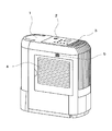
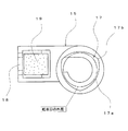
図1より、1は加湿装置の本体ケース、2は本体ケース1の上部に位置し加湿装置の運転を制御するための操作部で、この操作部2と隣接する上部に本体ケース1内で加湿された加湿空気を室内に排出するための吹出口3を設けている。また、4は室内の空気を本体ケース1内部に取り入れるための吸込口であり、5は室内の湿度を検出するための図示していない湿度センサに連通する通気口である。
From FIG. 1,
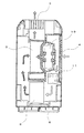
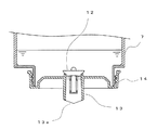
図2は加湿器の縦断面構成図であり、6は給水タンク7から供給された水を一定水量貯える水槽部、8は水槽部6内に配置され水槽部6の水を吸水して湿潤する気化フィルターである。9は送風ファンであり、10は送風ファン9を駆動するための送風モータである。さらに、11は吸込口4と気化フィルター8の間に配置され送風ファン9によって吸込口4から取り入れられた空気を加熱する温風用ヒータである。
FIG. 2 is a vertical cross-sectional configuration diagram of the humidifier, 6 is a water tank unit that stores a certain amount of water supplied from a
つまり、室内の空気が、吸込口4、温風用ヒータ11、気化フィルター8、送風ファン9、吹出口3から構成される通風経路を通過することにより加湿空気として再び室内に排出されることになる。なお、図における白矢印は本体ケース1内に取り入れられた空気の流れを、網掛け矢印は水分を含んだ加湿空気の流れを示している。
That is, the indoor air passes through the ventilation path composed of the
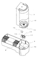
図3は水槽部6に給水タンク7を立設した状況を説明する分解傾斜図であり、給水タンク7には常閉弁からなる弁機構12を組み付けた給水口13を有する給水キャップ14を設けている。15は水槽部6に装着して給水タンク7からの水を一旦収容し、このときの水位上昇により給水タンク7からの給水を自動停止する小容量の受液収容部である。16は水槽部6に設けられたビン部であり、給水タンク7を水槽部6に立設した場合に給水キャップ14の弁機構12のバネを押し上げて給水口13を開放するものである。
FIG. 3 is an exploded perspective view for explaining the situation where the
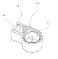
また、図4に示すように、受液収容部15は給水口13を挿入するための挿入部17と水槽部6と連通する排水部18から構成され、排水部18には水槽部6への排水を遅延させる排水規制手段19としてのスポンジを設けている。さらに、図5に示すように、挿入部17の内周壁形状は3つの辺部17aと3つの頂点部17bからなる略三角形としている。また、図6は給水タンク7に設けられた給水キャップ14の給水口13の拡大図であるが、給水口13の端部13aを略V字形状としている。
Further, as shown in FIG. 4, the liquid receiving
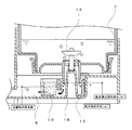
次に、上記の構成における動作を図7により説明する。給水タンク7を本体ケース1内の水槽部6に立設すると、水槽部6に設けられたビン部16が給水キャップ14の弁機構12のバネを押し上げて常閉弁が開き、給水タンク7から受液収容部15に給水される。そして、加湿器を運転しない場合には水槽部6と受液収容部15の水位は同じ高さとなる。
Next, the operation in the above configuration will be described with reference to FIG. When the
一方、加湿器の運転を開始すると、送風モータ10の駆動により送風ファン9が回転し、この回転による送風によって気化フィルター8にて水槽部6の水が気化して消費されると受液収容部15の水位より水槽部6の水位が下がるため、受液収容部15の排水部18から水槽部6に水が徐々に排水される。
On the other hand, when the operation of the humidifier is started, the blower fan 9 is rotated by driving the
受液収容部15内の水が水槽部6に排水されると、受液収容部15内の水位が下がり給水口13の端部13aが水面より開放されて給水が再開されるが(a水位)、排水規制手段19により徐々に水槽部6へ排水されているため、給水タンク7からの給水により受液収容部15内の水位は直ぐに上昇して給水口13の端部13aを塞ぐことから給水は短時間で停止する(b水位)。
When the water in the
しかし、受液収容部15内の水は水槽部6に徐々に排水され続けるため、直ぐに受液収容部15内の水位が下がり(a水位)、再び給水口13の端部13aが水面より開放されて受液収容部15に給水が再開されるから、再び受液収容部15内の水位が上昇して給水は停止する(b水位)。つまり、受液収容部15内の水位変化により給水タンク7からの少量の給水と停止を短時間に繰り返すことで給水タンク7には常に一定量の空気が少しずつ導入されることから、給水タンク7内には大きな気泡は発生しないのである。
However, since the water in the
また、給水口13が挿入される受液収容部15の挿入部17の内周壁形状を略三角形としているから、挿入部17の内周壁と給水口13の外周壁の隙間は略三角形の辺部17aでは小さくなるため、給水タンク7が傾いてセットされても給水口13の外周壁が辺部17aに押えつけられるため給水口13が傾くことはなく、頂点部17bでは一定の隙間を確保できるため、給水タンク7には常に一定量の空気が少しずつ導入されることから給水タンク7内には大きな気泡は発生しないのである。
Moreover, since the inner peripheral wall shape of the
さらに、給水口13の端部13aを略V字形状にすることにより、受液収容部15の水位が少し下がっただけで給水口13の端部13aの両側で表面張力を簡単に破ることができ、受液収容部15に対して給水口13が傾いて挿入されても端部13aの両側の一方で確実に表面張力を破ることができるため、給水タンク7には常に一定量の空気が少しずつ導入されることから給水タンク7内には大きな気泡は発生しないのである。
Furthermore, by making the end portion 13a of the
6 水槽部
7 給水タンク
12 弁機構
13 給水口
13a端部
15 受液収容部
17 挿入部
19 排水規制手段(スポンジ)
6
Claims (2)
A water supply tank provided with a water supply port, a water tank part for detachably installing the water supply tank, and a valve mechanism for opening the water tank by standing the water tank in the water tank part are provided in the water supply port, As the water level of the water tank portion decreases with consumption, air is introduced into the water supply tank as bubbles from the water supply port via the valve mechanism, and according to the amount of air introduced. In a water supply apparatus configured such that the amount of water is supplied to the water tank unit from the water supply port, the water level rises again, and the water supply is automatically stopped, the water supply from the water supply port is once accommodated in communication with the water tank unit, and the water level rises A liquid receiving container that automatically stops water supply is provided in the water tank part, and the liquid receiving container is provided with drainage restricting means for delaying drainage to the water tank part, and an insertion part into which the water supply port is inserted. The inner wall shape is almost polygonal Water and wherein the a.
Priority Applications (1)
| Application Number | Priority Date | Filing Date | Title |
|---|---|---|---|
| JP2006176381A JP4648256B2 (en) | 2006-06-27 | 2006-06-27 | Water supply equipment |
Applications Claiming Priority (1)
| Application Number | Priority Date | Filing Date | Title |
|---|---|---|---|
| JP2006176381A JP4648256B2 (en) | 2006-06-27 | 2006-06-27 | Water supply equipment |
Publications (2)
| Publication Number | Publication Date |
|---|---|
| JP2008008502A JP2008008502A (en) | 2008-01-17 |
| JP4648256B2 true JP4648256B2 (en) | 2011-03-09 |
Family
ID=39066883
Family Applications (1)
| Application Number | Title | Priority Date | Filing Date |
|---|---|---|---|
| JP2006176381A Active JP4648256B2 (en) | 2006-06-27 | 2006-06-27 | Water supply equipment |
Country Status (1)
| Country | Link |
|---|---|
| JP (1) | JP4648256B2 (en) |
Families Citing this family (4)
| Publication number | Priority date | Publication date | Assignee | Title |
|---|---|---|---|---|
| JP5103499B2 (en) * | 2010-03-26 | 2012-12-19 | パナソニック株式会社 | Mist generator and beauty device |
| KR101777235B1 (en) * | 2010-09-28 | 2017-09-11 | 코웨이 주식회사 | Humidification apparatus for preventing water leak |
| JP5747156B2 (en) * | 2011-01-07 | 2015-07-08 | パナソニックIpマネジメント株式会社 | Humidifier |
| JP6087235B2 (en) * | 2013-07-16 | 2017-03-01 | ダイニチ工業株式会社 | Humidifier |
Family Cites Families (6)
| Publication number | Priority date | Publication date | Assignee | Title |
|---|---|---|---|---|
| JP2596487Y2 (en) * | 1992-08-27 | 1999-06-14 | ティーディーケイ株式会社 | Steam humidifier |
| JP3129152B2 (en) * | 1995-06-15 | 2001-01-29 | 三菱電機株式会社 | humidifier |
| JP3329231B2 (en) * | 1997-05-22 | 2002-09-30 | タイガー魔法瓶株式会社 | Gas-liquid exchange structure when supplying liquid to the liquid supply tank |
| JP2000104954A (en) * | 1998-09-29 | 2000-04-11 | Sanyo Electric Co Ltd | Steam type humidifier |
| JP2001065931A (en) * | 1999-08-27 | 2001-03-16 | Aiwa Co Ltd | Sound deadening feed water cap, feed water tank and humidifier |
| JP2005127713A (en) * | 2005-02-02 | 2005-05-19 | Sanyo Electric Co Ltd | Humidifier |
-
2006
- 2006-06-27 JP JP2006176381A patent/JP4648256B2/en active Active
Also Published As
| Publication number | Publication date |
|---|---|
| JP2008008502A (en) | 2008-01-17 |
Similar Documents
| Publication | Publication Date | Title |
|---|---|---|
| EP3081872B1 (en) | Home appliance | |
| JP5241352B2 (en) | Humidifier | |
| JP2021156569A (en) | humidifier | |
| US9423141B2 (en) | Console humidifier | |
| JP6633015B2 (en) | Humidifier | |
| JP4648256B2 (en) | Water supply equipment | |
| JP4675846B2 (en) | Water supply equipment | |
| KR20090059725A (en) | Water supply device for humidification air cleaner | |
| CN107076440B (en) | Humidifying element and humidifying device | |
| CN116615625A (en) | Evaporation type humidifier | |
| KR102213126B1 (en) | Method for detecting water level of air washer | |
| KR102275558B1 (en) | Method for water supply control of air washer | |
| JP2011237135A (en) | Humidifying apparatus | |
| JP6706753B2 (en) | Air conditioner | |
| JP2008267759A (en) | Humidifier | |
| KR20130074164A (en) | Humidifying Air Purifier | |
| JP3776423B2 (en) | humidifier | |
| JP3776424B2 (en) | humidifier | |
| KR101335110B1 (en) | Humidifier | |
| CN102410599A (en) | Humidifier | |
| JP4033171B2 (en) | Humidifier | |
| JP7671939B2 (en) | Air Purifier | |
| JP2010019446A (en) | Water storage tank and humidifier | |
| JP4652171B2 (en) | humidifier | |
| KR20230157659A (en) | Humidifier and control method the same |
Legal Events
| Date | Code | Title | Description |
|---|---|---|---|
| A621 | Written request for application examination |
Free format text: JAPANESE INTERMEDIATE CODE: A621 Effective date: 20090518 |
|
| A977 | Report on retrieval |
Free format text: JAPANESE INTERMEDIATE CODE: A971007 Effective date: 20101018 |
|
| A131 | Notification of reasons for refusal |
Free format text: JAPANESE INTERMEDIATE CODE: A131 Effective date: 20101026 |
|
| A521 | Request for written amendment filed |
Free format text: JAPANESE INTERMEDIATE CODE: A523 Effective date: 20101028 |
|
| TRDD | Decision of grant or rejection written | ||
| A01 | Written decision to grant a patent or to grant a registration (utility model) |
Free format text: JAPANESE INTERMEDIATE CODE: A01 Effective date: 20101207 |
|
| A01 | Written decision to grant a patent or to grant a registration (utility model) |
Free format text: JAPANESE INTERMEDIATE CODE: A01 |
|
| A61 | First payment of annual fees (during grant procedure) |
Free format text: JAPANESE INTERMEDIATE CODE: A61 Effective date: 20101209 |
|
| FPAY | Renewal fee payment (event date is renewal date of database) |
Free format text: PAYMENT UNTIL: 20131217 Year of fee payment: 3 |
|
| R150 | Certificate of patent or registration of utility model |
Ref document number: 4648256 Country of ref document: JP Free format text: JAPANESE INTERMEDIATE CODE: R150 Free format text: JAPANESE INTERMEDIATE CODE: R150 |
|
| FPAY | Renewal fee payment (event date is renewal date of database) |
Free format text: PAYMENT UNTIL: 20141217 Year of fee payment: 4 |
|
| R250 | Receipt of annual fees |
Free format text: JAPANESE INTERMEDIATE CODE: R250 |
|
| R250 | Receipt of annual fees |
Free format text: JAPANESE INTERMEDIATE CODE: R250 |
|
| R250 | Receipt of annual fees |
Free format text: JAPANESE INTERMEDIATE CODE: R250 |
|
| R250 | Receipt of annual fees |
Free format text: JAPANESE INTERMEDIATE CODE: R250 |
|
| R250 | Receipt of annual fees |
Free format text: JAPANESE INTERMEDIATE CODE: R250 |
|
| R250 | Receipt of annual fees |
Free format text: JAPANESE INTERMEDIATE CODE: R250 |