EP3078860B1 - Querstromventilatorschaufel - Google Patents
Querstromventilatorschaufel Download PDFInfo
- Publication number
- EP3078860B1 EP3078860B1 EP14875882.4A EP14875882A EP3078860B1 EP 3078860 B1 EP3078860 B1 EP 3078860B1 EP 14875882 A EP14875882 A EP 14875882A EP 3078860 B1 EP3078860 B1 EP 3078860B1
- Authority
- EP
- European Patent Office
- Prior art keywords
- blade
- cross
- edge portion
- thickness
- flow fan
- Prior art date
- Legal status (The legal status is an assumption and is not a legal conclusion. Google has not performed a legal analysis and makes no representation as to the accuracy of the status listed.)
- Active
Links
- 230000007423 decrease Effects 0.000 description 11
- 238000000926 separation method Methods 0.000 description 7
- 238000004378 air conditioning Methods 0.000 description 4
- 230000000694 effects Effects 0.000 description 3
- 230000002829 reductive effect Effects 0.000 description 3
- 230000002159 abnormal effect Effects 0.000 description 2
- 238000007664 blowing Methods 0.000 description 2
- 230000036961 partial effect Effects 0.000 description 2
- 230000015556 catabolic process Effects 0.000 description 1
- 238000001816 cooling Methods 0.000 description 1
- 230000003247 decreasing effect Effects 0.000 description 1
- 238000010438 heat treatment Methods 0.000 description 1
- 230000002401 inhibitory effect Effects 0.000 description 1
- 239000002184 metal Substances 0.000 description 1
Images


Classifications
-
- F—MECHANICAL ENGINEERING; LIGHTING; HEATING; WEAPONS; BLASTING
- F04—POSITIVE - DISPLACEMENT MACHINES FOR LIQUIDS; PUMPS FOR LIQUIDS OR ELASTIC FLUIDS
- F04D—NON-POSITIVE-DISPLACEMENT PUMPS
- F04D29/00—Details, component parts, or accessories
- F04D29/26—Rotors specially for elastic fluids
- F04D29/28—Rotors specially for elastic fluids for centrifugal or helico-centrifugal pumps for radial-flow or helico-centrifugal pumps
- F04D29/281—Rotors specially for elastic fluids for centrifugal or helico-centrifugal pumps for radial-flow or helico-centrifugal pumps for fans or blowers
- F04D29/282—Rotors specially for elastic fluids for centrifugal or helico-centrifugal pumps for radial-flow or helico-centrifugal pumps for fans or blowers the leading edge of each vane being substantially parallel to the rotation axis
- F04D29/283—Rotors specially for elastic fluids for centrifugal or helico-centrifugal pumps for radial-flow or helico-centrifugal pumps for fans or blowers the leading edge of each vane being substantially parallel to the rotation axis rotors of the squirrel-cage type
-
- F—MECHANICAL ENGINEERING; LIGHTING; HEATING; WEAPONS; BLASTING
- F04—POSITIVE - DISPLACEMENT MACHINES FOR LIQUIDS; PUMPS FOR LIQUIDS OR ELASTIC FLUIDS
- F04D—NON-POSITIVE-DISPLACEMENT PUMPS
- F04D17/00—Radial-flow pumps, e.g. centrifugal pumps; Helico-centrifugal pumps
- F04D17/02—Radial-flow pumps, e.g. centrifugal pumps; Helico-centrifugal pumps having non-centrifugal stages, e.g. centripetal
- F04D17/04—Radial-flow pumps, e.g. centrifugal pumps; Helico-centrifugal pumps having non-centrifugal stages, e.g. centripetal of transverse-flow type
-
- F—MECHANICAL ENGINEERING; LIGHTING; HEATING; WEAPONS; BLASTING
- F04—POSITIVE - DISPLACEMENT MACHINES FOR LIQUIDS; PUMPS FOR LIQUIDS OR ELASTIC FLUIDS
- F04D—NON-POSITIVE-DISPLACEMENT PUMPS
- F04D29/00—Details, component parts, or accessories
- F04D29/26—Rotors specially for elastic fluids
- F04D29/28—Rotors specially for elastic fluids for centrifugal or helico-centrifugal pumps for radial-flow or helico-centrifugal pumps
- F04D29/30—Vanes
-
- F—MECHANICAL ENGINEERING; LIGHTING; HEATING; WEAPONS; BLASTING
- F04—POSITIVE - DISPLACEMENT MACHINES FOR LIQUIDS; PUMPS FOR LIQUIDS OR ELASTIC FLUIDS
- F04D—NON-POSITIVE-DISPLACEMENT PUMPS
- F04D29/00—Details, component parts, or accessories
- F04D29/66—Combating cavitation, whirls, noise, vibration or the like; Balancing
- F04D29/661—Combating cavitation, whirls, noise, vibration or the like; Balancing especially adapted for elastic fluid pumps
-
- F—MECHANICAL ENGINEERING; LIGHTING; HEATING; WEAPONS; BLASTING
- F24—HEATING; RANGES; VENTILATING
- F24F—AIR-CONDITIONING; AIR-HUMIDIFICATION; VENTILATION; USE OF AIR CURRENTS FOR SCREENING
- F24F1/00—Room units for air-conditioning, e.g. separate or self-contained units or units receiving primary air from a central station
- F24F1/0007—Indoor units, e.g. fan coil units
- F24F1/0018—Indoor units, e.g. fan coil units characterised by fans
- F24F1/0025—Cross-flow or tangential fans
Definitions
- the present invention relates to a blade of a cross-flow fan.
- cross-flow fans are often used in order to blow air.
- an pressure surface of the blade and a suction surface opposite the pressure surface are curved along a direction of rotation of the fan further toward the outer side of the blade from a fan rotary shaft, and, near the center of the blade, are formed in an arc shape set apart from a straight line connecting an inner-peripheral part and an outer-peripheral part of the blade.
- the thickness of the blade decreases further toward the outer-peripheral side of a fan so that the distance between blades in a direction perpendicular to a direction of airflow between the blades is substantially the same on the outer-peripheral side and inner-peripheral side of the fan.
- a flow vented out from the fan separates off, at a suction surface side having large curvature, in proportion with direction from an inner-peripheral end of the blade toward an outer-peripheral end of the blade, and readily gives rise to turbulence.
- the problem of the present invention is to obtain a blade of a cross-flow fan with which it is possible to provide a cross-flow fan that is highly efficient and that produces little noise even when high loads are applied.
- the present invention regards a blade of a cross-flow fan according to claim 1.
- FIG. 1 is a schematic view of a cross-section of an indoor unit 1 of an air-conditioning apparatus.
- the indoor unit 1 comprises a main casing 2, an air filter 3, an indoor heat exchanger 4, a cross-flow fan 10, a vertical flap 5, and a horizontal flap 6.
- the air filter 3 is arranged downstream from an intake port 2a in a ceiling surface of the main casing 2, the air filter 3 facing the intake port 2a.
- the indoor heat exchanger 4 is arranged further downstream from the air filter 3.
- the indoor heat exchanger 4 is configured by linking a front-surface-side heat exchanger 4a and a rear-surface-side heat exchanger 4b so as to form an inverse V-shape as viewed from a side surface.
- the front-surface-side heat exchanger 4a and the rear-surface-side heat exchanger 4b are configured by attaching a plurality of plate fins to a heat-transfer pipe aligned in parallel with one another in a width direction of the indoor unit 1.
- All indoor air that passes through the intake port 2a and reaches the indoor heat exchanger 4 passes through the air filter 3, and dirt and grit in the indoor air is removed therefrom.
- the indoor air that has been drawn in through the intake port 2a and passed through the air filter 3 is subjected to heat-exchange and air-conditioning when passing between the plate fins of the front-surface-side heat exchanger 4a and rear-surface-side heat exchanger 4b.
- the cross-flow fan 10 which is substantially cylindrical in shape, is provided downstream from the indoor heat exchanger 4, the cross-flow fan 10 extending longitudinally along a width direction of the main casing 2.
- the cross-flow fan 10 is arranged in parallel with the indoor heat exchanger 4.
- the cross-flow fan 10 comprises an impeller 20 arranged in a space surrounded so as to be sandwiched in the inverse V-shape of the indoor heat exchanger 4, and a fan motor (not shown) configured and arranged to drive the impeller 20.
- the cross-flow fan 10 generates an airflow from the indoor heat exchanger 4 toward a vent 2b by the rotation of the impeller 20 in a direction A1 shown by arrows in FIG. 1 (i.e., clockwise).
- the cross-flow fan 10 is a transverse fan, configured such that the airflow passes transversely across the cross-flow fan 10.
- a rear-surface side of a vent passage linked to the vent 2b downstream from the cross-flow fan 10 is configured from a scroll member 2c.
- a lower end of the scroll member 2c is linked to a lower edge of an opening of the vent 2b.
- a guide surface of the scroll member 2c has a smooth curved shape having a center of curvature on the cross-flow-fan 10 side as viewed in cross-section.
- a tongue part 2d is formed on the front-surface side of the cross-flow fan 10, and an upper surface of the vent passage that is continuous from the tongue part 2d is linked to an upper edge of the vent 2b.
- a direction in which the airflow is vented out from the vent 2b is adjusted using the vertical flap 5 and horizontal flap 6.
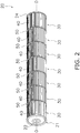
- FIG. 2 shows a schematic structure of the impeller 20 of the cross-flow fan 10.
- the impeller 20 is configured such that, e.g., end plates 21, 24 and a plurality of fan blocks 30 are joined together. In the present embodiment, seven fan blocks 30 are joined together.
- An end plate 21 is arranged on one end of the impeller 20, and a metal rotary shaft 22 is provided along a central axis O.
- Each of the fan blocks 30 comprises a plurality of blades 40 and an annular support plate 50.
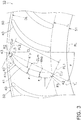
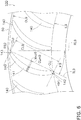
- FIG. 3 shows a plurality of blades 40 secured to the support plate 50 of one of the fan blocks 30.
- the support plate 50 is annular in shape, and has an inner-peripheral end 51 on the inner-peripheral side of the cross-flow fan 10, and an outer-peripheral end 52 on the outer-peripheral side of the cross-flow fan 10.
- Each of the blades 40 is configured from a base portion 41, a leading-edge portion 42, and a trailing-edge portion 43.
- the following cross-sectional shape is employed in common in all of the blades 40 arranged on one of the fan blocks 30, as viewed in a cross-section taken along a plane parallel to the support plate 50. All of the blades 40 arranged on one of the fan blocks 30 are arranged tangent to one inscribed circle IL and one circumscribed circle OL, which are concentric with respect to the inner-peripheral end 51 and the outer-peripheral end 52.
- the leading-edge portion 42 is formed so as to describe a smooth, convex, arc-like shape on the inner-peripheral side of the blade 40, the leading-edge portion 42 having a surface of arc-like cross-section.
- the trailing-edge portion 43 is formed so as to describe a smooth, convex, arc-like shape on the outer-peripheral side of the blade 40, the trailing-edge portion 43 having a surface of arc-like cross-section.
- the base portion 41 is formed between the leading-edge portion 42 and the trailing-edge portion 43, the base portion having a pressure surface 41p and a suction surface 41n.
- the pressure surface 41p of the base portion 41 generates positive pressure
- the suction surface 41n of the base portion 41 generates negative pressure.
- Each of the blades 40 is inclined by an angle ⁇ with respect to a radial line RL intersecting a central axis O of the cross-flow fan 10, the radial line RL extending radially outward from the central axis O.
- the angle of inclination ⁇ of the blade 40 is defined as an angle formed by the radial line RL and a tangent line TL on the inner-peripheral side of the blade 40.
- the pressure surface 41p and suction surface 41n of each of the blades 40 are curved so as to describe smooth arcs that expand toward the outer-peripheral side in cross-section. Because the blades 40 have an angle of inclination ⁇ with respect to radial lines RL, both the center of curvature of the arc of the pressure surface 41p and the center of curvature of the arc of the suction surface 41n are positioned on the inner-peripheral-surface side.
- a chord length CL is the length from a leading end of the leading-edge portion 42 to a trailing end of the trailing-edge portion 43.
- the tangent line TL on the inner-peripheral side of the blade 40 is extended to the inner-peripheral side and outer-peripheral side of the cross-flow fan
- a perpendicular line PL1 is drawn perpendicular to the tangent line TL on the inner-peripheral side of the blade 40 so as to be tangent to the leading-edge portion 42
- a perpendicular line PL2 is drawn perpendicular to the tangent line TL so as to be tangent to the trailing-edge portion 43.
- the length from the perpendicular line PL1 to the perpendicular line PL2 constitutes the chord length CL.
- the blades 40 are configured such that the thickness of the base portion 41; i.e., the distance between the pressure surface 41p and the suction surface 41n varies gradually further from the inner-peripheral side toward the outer-peripheral side. Therefore, there is one location where the thickness of the base portion 41 is greatest.
- the position where the thickness of the base portion 41 is greatest is referred to below as the "position of maximum thickness.”
- the thickness of the base portion 41 is defined as the space between the pressure surface 41p and the suction surface 41n in a direction perpendicular to the pressure surface 41p.
- the position of maximum thickness is indicated at a position at the foot of a perpendicular line drawn from an intermediate position between the pressure surface 41p and the suction surface 41n to the tangent line TL defining the chord length CL.
- the performance of the cross-flow fan 10 is strongly impacted by the cross-sectional shape of the blades 40.
- a cross-sectional shape of the blades 40 that is configured and arranged to elicit excellent performance from the cross-flow fan 10 is described below.
- Each of the blades 40 is formed such that the radius R1 of the arc of the leading-edge portion 42 is greater than the radius R2 of the arc of the trailing-edge portion 43.
- the radius R1 of the arc of the leading-edge portion 42 and the radius R2 of the arc of the trailing-edge portion 43 may be set so as to satisfy the relationship R1/R2 > 1.5, and more preferably to satisfy the relationship R1/R2 > 1.75.
- the position Mxp of maximum thickness of a blade 40 is positioned closer to the leading-edge portion 42 than to the trailing-edge portion 43. Specifically, the position Mxp of maximum thickness may be positioned closer to the leading-edge portion 42 than to an intermediate position CLm along the chord length.
- the blades 40 have a cross-sectional shape such that the relationship ⁇ / ⁇ > ⁇ / ⁇ is satisfied, where the maximum thickness is designated as the maximum thickness ⁇ , the thickness at an intermediate position CLm along the chord length CL is designated as an intermediate thickness ⁇ , and the thickness at an outer-peripheral-side position CL5 set apart from an outer-peripheral end CLp of the blade chord by 5% of the chord length CL is designated as an outer-peripheral-side thickness ⁇ .
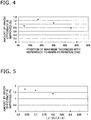
- FIG. 4 shows the relationship between the position Mxp of maximum thickness and the amount by which efficiency is improved.
- the horizontal axis represents a ratio of the chord length CL and the position Mxp of maximum thickness with reference to an inner-peripheral end CLi of the blade chord.
- the vertical axis represents a rate of decrease from a shaft power of blades 140 having a conventional shape as shown in FIG. 6 .
- the rate of decrease is given by the formula (SPo - SPn)/SPo ⁇ 100 (%), where SPo indicates the shaft power required for a conventional cross-flow fan 100 using conventional blades 140 to obtain a prescribed airflow, and SPn indicates the shaft power required for the cross-flow fan 10 using the blades 40 to obtain the same airflow.
- the value of ⁇ / ⁇ )/( ⁇ / ⁇ ) is set to 0.64.
- the radius of an inscribed circle IL9 is approximately equal to the radius of the inscribed circle IL of the cross-flow fan 10
- the radius of a circumscribed circle OL9 is approximately equal to the radius of the circumscribed circle OL of the cross-flow fan 10.
- a chord length CL9 of each of the blades 140 is approximately equal to the chord length CL of each of the blades 40
- the angle of inclination ⁇ 9 is approximately equal to the angle of inclination ⁇ of the blades 40.
- a position Mxp9 of maximum thickness in each of the blades 140 is positioned in the vicinity of an intermediate position CLm9 along the chord length CL9, and is positioned further toward the outer-peripheral side than is the intermediate position CLm9. Due to being configured in such an arrangement, the blades 140 are formed in a crescent-form cross-sectional shape such that the thickness decreases in the same manner toward the inner-peripheral side and the outer-peripheral side.
- the distance from the inner-peripheral end CLi to the position Mxp of maximum thickness is set within a range of 5-45% of the chord length CL. This is because, while an improvement in efficiency in an amount of 0.8-1.3% can be expected when the distance from the inner-peripheral end CLi to the position Mxp of maximum thickness is within a range of 5-45% of the chord length CL, the amount by which efficiency is improved rapidly declines in correspondence with distance from this range.
- FIG. 5 shows the relationship between the amount by which efficiency is improved and the ratio of ( ⁇ / ⁇ ) and ( ⁇ / ⁇ ).
- the amount of improvement shown in FIG. 5 is the rate of decrease from the shaft power of blades for comparison, such as the blades disclosed in Patent Document 1, in which the position of maximum thickness is at a location 4% of a chord length from an inner-peripheral end, the radius of the leading-edge portion is approximately equal to the radius R1 of the leading-edge portion 42 of the blade 40, and the radius of the trailing-edge portion is approximately equal to the radius R2 of the trailing-edge portion 43 of the blade 40.
- the cross-sections of the pressure surface and suction surface between the position of maximum thickness and the trailing-edge portion draw a single arc, and the blades have a cross-sectional shape such that the thickness decreases uniformly.
- the position Mxp of maximum thickness is set to a location 17% from the inner-peripheral end.
- the blades 40 of the cross-flow fan 10 are formed such that the radius R1 of the leading-edge portion 42 is greater than the radius R2 of the trailing-edge portion 43. Additionally, the base portion 41 of each of the blades 40 has a maximum thickness ⁇ at a position Mxp of maximum thickness that is closer to the leading-edge portion 42 than to the trailing-edge portion 43. Additionally, the blades 40 have a thickness ⁇ (an example of a first thickness) at an intermediate position CLm along the blade chord, and a thickness ⁇ (an example of a second thickness) at an outer-peripheral-side position CL5 set apart from the outer-peripheral end CLp of the blade chord by 5% of the chord length.
- the blades 40 are also formed such that the value obtained by dividing the thickness ⁇ located at the intermediate position CLm along the blade chord by the maximum thickness ⁇ is greater than the value obtained by dividing the thickness ⁇ located at the outer-peripheral-side position CL5 by the thickness ⁇ .
- the cross-sectional shape of the blades 40 is formed so as to satisfy the relationship ⁇ / ⁇ > ⁇ / ⁇ .
- the base portion 41 of each of the blades 40 is formed such that the maximum thickness ⁇ is positioned within a range of 5-45% of the chord length CL from the inner-peripheral end. Specifically, the base portion 41 is formed so as to satisfy the relationship 5 ⁇ (distance from inner-peripheral end CLi to position Mxp of maximum thickness)/CL ⁇ 100 ⁇ 45. Additionally, the base portion 41 is configured such that the value of the ratio (( ⁇ / ⁇ )/( ⁇ / ⁇ )) between the value obtained by dividing the thickness ⁇ located at the outer-peripheral-side position CL5 by the thickness ⁇ located at the intermediate position CLm along the blade chord and the value obtained by dividing the thickness ⁇ by the maximum thickness ⁇ is set to 0.85 or less.
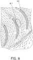
- FIG. 8 is a schematic view of an airflow flowing around a blade 40.
- FIG. 9 is a schematic view of an airflow flowing around a conventional blade 140 (see FIG. 6 ) with reference to the amount by which efficiency is improved in FIG. 4 described above.
- FIG. 10 is schematic view of an airflow flowing around a conventional blade 240 with reference to the amount by which efficiency is improved in FIG. 5 described above.
- the chain double-dash lines indicate blade-side portions where the airflow travels at a relatively slower speed.
- the position Mxp of maximum thickness is located at a position closer to the leading-edge portion 42 than to the intermediate position CLm along the blade chord; i.e., closer to the inner-peripheral side than to the middle of the blade, whereby separation of flow at the suction surface 41n (region Ar1 in FIG. 8 ) from the leading-edge portion 42 of the blade 40 to the trailing-edge portion 43 of the blade 40 is minimized.
- the blade surface at the suction surface has a small curvature because the thickness is smoothly reduced as far as a location near the middle of the blade, it is possible, even if separation of suction surface-side flow occurs, to quickly rejoin the flow at the suction surface and minimize separation to the middle of the blade.
- the conventional blade 140 shown in FIG. 9 because the thickness rapidly decreases from the portion of maximum thickness in the blade 140, separation readily occurs at a region Ar2.
- the flow from the leading-edge portion 42 to the trailing-edge portion 43 is accelerated, turbulence is suppressed, and low-frequency narrowband noise such as N noise is reduced.
- low-frequency narrowband N noise is reduced as shown in FIG. 7 .
- a pronounced effect for reducing N noise is realized by switching from the conventional blade 140 to the blade 40 according to the present embodiment.
Landscapes
- Engineering & Computer Science (AREA)
- Mechanical Engineering (AREA)
- General Engineering & Computer Science (AREA)
- Chemical & Material Sciences (AREA)
- Combustion & Propulsion (AREA)
- Structures Of Non-Positive Displacement Pumps (AREA)
Claims (1)
- Schaufel eines Querstromgebläses, umfassend:einen Vorderkantenabschnitt (42), der auf der Innenumfangsseite des Querstromgebläses (10) angeordnet ist, wobei der Vorderkantenabschnitt in einer bogenartigen Form gebildet ist;einen Hinterkantenabschnitt (43), der in der Außenumfangsseite des Querstromgebläses angeordnet ist, wobei der Hinterkantenabschnitt in einer bogenartigen Form gebildet ist; undeinen Basisabschnitt (41), der zwischen dem Vorderkantenabschnitt und dem Hinterkantenabschnitt gebildet ist, wobei der Basisabschnitt eine Druckfläche (41p), die konfiguriert und angeordnet ist, um positiven Druck zu erzeugen, und eine Saugfläche (41n) aufweist, die konfiguriert und angeordnet ist, um negativen Druck zu erzeugen;wobei der Vorderkantenabschnitt und der Hinterkantenabschnitt so gebildet sind, dass der Radius des Vorderkantenabschnitts größer als der Radius des Hinterkantenabschnitts ist;wobei die Druckfläche (41p) und Saugfläche (41n) der Schaufel (40) gekrümmt sind, um ebenmäßige Bögen zu beschreiben, die sich im Querschnitt zur Außenumfangsseite erstrecken;wobei sich der Abstand zwischen der Druckfläche (41p) und der Saugfläche (41n) schrittweise von der Innenumfangsseite zur Außenumfangsseite ändert; undder Basisabschnitt so gebildet ist, dass er eine maximale Dicke an einer Position maximaler Dicke, eine erste Dicke an einer Zwischenposition auf einer Schaufelsehne und eine zweite Dicke an einer Position, die von einem Außenumfangsende der Schaufelsehne um 5 % der Sehnenlänge beabstandet ist, aufweist;wobeider Basisabschnitt so konfiguriert ist, dass die Position maximaler Dicke innerhalb eines Bereichs von 5-45 % der Sehnenlänge von einem Innenumfangsende positioniert ist; und wobeider Basisabschnitt so konfiguriert ist, dass der Wert des Verhältnisses zwischen dem Wert, der durch Dividieren der zweiten Dicke durch die erste Dicke erhalten wird, und dem Wert, der durch Dividieren der ersten Dicke durch die maximale Dicke erhalten wird, auf 0,85 oder weniger eingestellt ist.
Applications Claiming Priority (2)
| Application Number | Priority Date | Filing Date | Title |
|---|---|---|---|
| JP2013272151A JP5825339B2 (ja) | 2013-12-27 | 2013-12-27 | クロスフローファンの翼 |
| PCT/JP2014/083543 WO2015098689A1 (ja) | 2013-12-27 | 2014-12-18 | クロスフローファンの翼 |
Publications (3)
| Publication Number | Publication Date |
|---|---|
| EP3078860A1 EP3078860A1 (de) | 2016-10-12 |
| EP3078860A4 EP3078860A4 (de) | 2017-01-11 |
| EP3078860B1 true EP3078860B1 (de) | 2019-02-27 |
Family
ID=53478550
Family Applications (1)
| Application Number | Title | Priority Date | Filing Date |
|---|---|---|---|
| EP14875882.4A Active EP3078860B1 (de) | 2013-12-27 | 2014-12-18 | Querstromventilatorschaufel |
Country Status (9)
| Country | Link |
|---|---|
| US (1) | US10690142B2 (de) |
| EP (1) | EP3078860B1 (de) |
| JP (1) | JP5825339B2 (de) |
| CN (1) | CN105849417B (de) |
| AU (1) | AU2014371353B2 (de) |
| BR (1) | BR112016014694B1 (de) |
| ES (1) | ES2727422T3 (de) |
| MY (1) | MY183273A (de) |
| WO (1) | WO2015098689A1 (de) |
Families Citing this family (4)
| Publication number | Priority date | Publication date | Assignee | Title |
|---|---|---|---|---|
| JP6210104B2 (ja) * | 2015-10-30 | 2017-10-11 | ダイキン工業株式会社 | クロスフローファン |
| CN108180166A (zh) * | 2017-12-26 | 2018-06-19 | 博耐尔汽车电气系统有限公司 | 一种空调电机风扇叶轮结构 |
| KR102096160B1 (ko) * | 2018-03-29 | 2020-04-01 | 주식회사 원진일렉트로닉스 | 송풍기의 다익 원심 팬 |
| JP6852768B1 (ja) | 2019-09-30 | 2021-03-31 | ダイキン工業株式会社 | クロスフローファンの翼、クロスフローファン及び空調室内機 |
Family Cites Families (15)
| Publication number | Priority date | Publication date | Assignee | Title |
|---|---|---|---|---|
| US3952971A (en) * | 1971-11-09 | 1976-04-27 | The United States Of America As Represented By The Administrator Of The National Aeronautics And Space Administration | Airfoil shape for flight at subsonic speeds |
| JPH0579492A (ja) | 1991-09-20 | 1993-03-30 | Daikin Ind Ltd | 横流フアン |
| JP3107711B2 (ja) * | 1994-08-09 | 2000-11-13 | 株式会社東芝 | 横流ファン |
| JP3504363B2 (ja) * | 1995-01-30 | 2004-03-08 | 三菱電機株式会社 | 横断流送風機の羽根車 |
| US6565334B1 (en) * | 1998-07-20 | 2003-05-20 | Phillip James Bradbury | Axial flow fan having counter-rotating dual impeller blade arrangement |
| US6261051B1 (en) * | 1998-09-02 | 2001-07-17 | Gordon A. Kolacny | Fan duct combination unit |
| JP3661579B2 (ja) * | 1999-10-22 | 2005-06-15 | 松下電器産業株式会社 | 空気調和機の室内ユニット |
| JP3866897B2 (ja) * | 2000-03-21 | 2007-01-10 | 三菱電機株式会社 | 貫流送風機および空気調和機 |
| JP4583095B2 (ja) * | 2004-07-27 | 2010-11-17 | 東芝キヤリア株式会社 | クロスフローファン |
| FR2898943B1 (fr) * | 2006-03-23 | 2012-08-31 | Valeo Systemes Thermiques | Helice de ventilateur, en particulier pour vehicules automobiles |
| ES2294927B1 (es) * | 2006-05-31 | 2009-02-16 | Gamesa Eolica, S.A. | Pala de aerogenerador con borde de salida divergente. |
| JP2009036138A (ja) * | 2007-08-03 | 2009-02-19 | Hitachi Appliances Inc | 空気調和機 |
| CN103089661B (zh) * | 2011-11-04 | 2015-04-01 | 上海交通大学 | 横流风扇 |
| JP5143317B1 (ja) * | 2012-04-06 | 2013-02-13 | 三菱電機株式会社 | 空気調和装置の室内機 |
| CN202991621U (zh) * | 2012-07-16 | 2013-06-12 | 广东美的暖通设备有限公司 | 一种风轮叶片、贯流风轮及空调 |
-
2013
- 2013-12-27 JP JP2013272151A patent/JP5825339B2/ja active Active
-
2014
- 2014-12-18 WO PCT/JP2014/083543 patent/WO2015098689A1/ja active Application Filing
- 2014-12-18 BR BR112016014694-8A patent/BR112016014694B1/pt active IP Right Grant
- 2014-12-18 CN CN201480070915.8A patent/CN105849417B/zh active Active
- 2014-12-18 US US15/107,434 patent/US10690142B2/en active Active
- 2014-12-18 MY MYPI2016702106A patent/MY183273A/en unknown
- 2014-12-18 AU AU2014371353A patent/AU2014371353B2/en active Active
- 2014-12-18 EP EP14875882.4A patent/EP3078860B1/de active Active
- 2014-12-18 ES ES14875882T patent/ES2727422T3/es active Active
Non-Patent Citations (1)
| Title |
|---|
| None * |
Also Published As
| Publication number | Publication date |
|---|---|
| CN105849417B (zh) | 2017-12-01 |
| EP3078860A4 (de) | 2017-01-11 |
| MY183273A (en) | 2021-02-18 |
| AU2014371353A1 (en) | 2016-08-04 |
| CN105849417A (zh) | 2016-08-10 |
| JP2015124766A (ja) | 2015-07-06 |
| EP3078860A1 (de) | 2016-10-12 |
| US20170002827A1 (en) | 2017-01-05 |
| US10690142B2 (en) | 2020-06-23 |
| JP5825339B2 (ja) | 2015-12-02 |
| AU2014371353B2 (en) | 2017-07-27 |
| WO2015098689A1 (ja) | 2015-07-02 |
| BR112016014694A2 (de) | 2017-08-08 |
| ES2727422T3 (es) | 2019-10-16 |
| BR112016014694B1 (pt) | 2022-05-17 |
Similar Documents
| Publication | Publication Date | Title |
|---|---|---|
| US9995303B2 (en) | Air conditioner | |
| US9267511B2 (en) | Turbofan and indoor unit of air-conditioning apparatus including the same | |
| US9829004B2 (en) | Turbo fan and air conditioner | |
| US20110023526A1 (en) | Centrifugal fan | |
| US10052931B2 (en) | Outdoor cooling unit in vehicle air-conditioning apparatus | |
| EP3078860B1 (de) | Querstromventilatorschaufel | |
| KR20080104169A (ko) | 다익 팬 | |
| EP2957443B1 (de) | Aussenkühleinheit für eine klimaanlagenvorrichtung für ein fahrzeug | |
| KR20050005086A (ko) | 축류팬 쉬라우드의 스테이터 | |
| EP2530331B1 (de) | Axiallüfterbaugruppe für ein Fahrzeugkühlsystem | |
| US10400605B2 (en) | Turbofan and indoor unit for air conditioning apparatus | |
| US20100092286A1 (en) | Axial flow fan | |
| US9303649B2 (en) | Cross flow fan and air-conditioning apparatus including same | |
| EP3043077A1 (de) | Propellerlüfter, luftblasvorrichtung und ausseneinheit | |
| JP6611676B2 (ja) | 送風機および冷凍サイクル装置の室外機 | |
| JP2017180094A (ja) | 送風ファンおよびこれを用いた送風ユニット | |
| US20150204345A1 (en) | Propeller fan | |
| CN114502842B (zh) | 横流风扇的叶片、横流风扇和空调室内机 | |
| CN210921589U (zh) | 离心风轮和空调器 | |
| EP3015775B1 (de) | Innenraumeinheit für eine klimaanlagenvorrichtung | |
| WO2020026373A1 (ja) | 貫流ファンおよび空気調和機 |
Legal Events
| Date | Code | Title | Description |
|---|---|---|---|
| PUAI | Public reference made under article 153(3) epc to a published international application that has entered the european phase |
Free format text: ORIGINAL CODE: 0009012 |
|
| 17P | Request for examination filed |
Effective date: 20160706 |
|
| AK | Designated contracting states |
Kind code of ref document: A1 Designated state(s): AL AT BE BG CH CY CZ DE DK EE ES FI FR GB GR HR HU IE IS IT LI LT LU LV MC MK MT NL NO PL PT RO RS SE SI SK SM TR |
|
| AX | Request for extension of the european patent |
Extension state: BA ME |
|
| A4 | Supplementary search report drawn up and despatched |
Effective date: 20161209 |
|
| RIC1 | Information provided on ipc code assigned before grant |
Ipc: F04D 17/04 20060101AFI20161205BHEP Ipc: F04D 29/30 20060101ALI20161205BHEP Ipc: F04D 29/28 20060101ALI20161205BHEP Ipc: F04D 29/66 20060101ALI20161205BHEP Ipc: F24F 1/00 20110101ALI20161205BHEP |
|
| DAX | Request for extension of the european patent (deleted) | ||
| GRAP | Despatch of communication of intention to grant a patent |
Free format text: ORIGINAL CODE: EPIDOSNIGR1 |
|
| STAA | Information on the status of an ep patent application or granted ep patent |
Free format text: STATUS: GRANT OF PATENT IS INTENDED |
|
| INTG | Intention to grant announced |
Effective date: 20181012 |
|
| GRAS | Grant fee paid |
Free format text: ORIGINAL CODE: EPIDOSNIGR3 |
|
| GRAA | (expected) grant |
Free format text: ORIGINAL CODE: 0009210 |
|
| STAA | Information on the status of an ep patent application or granted ep patent |
Free format text: STATUS: THE PATENT HAS BEEN GRANTED |
|
| AK | Designated contracting states |
Kind code of ref document: B1 Designated state(s): AL AT BE BG CH CY CZ DE DK EE ES FI FR GB GR HR HU IE IS IT LI LT LU LV MC MK MT NL NO PL PT RO RS SE SI SK SM TR |
|
| REG | Reference to a national code |
Ref country code: GB Ref legal event code: FG4D |
|
| REG | Reference to a national code |
Ref country code: CH Ref legal event code: EP |
|
| REG | Reference to a national code |
Ref country code: AT Ref legal event code: REF Ref document number: 1101771 Country of ref document: AT Kind code of ref document: T Effective date: 20190315 |
|
| REG | Reference to a national code |
Ref country code: IE Ref legal event code: FG4D |
|
| REG | Reference to a national code |
Ref country code: DE Ref legal event code: R096 Ref document number: 602014042108 Country of ref document: DE |
|
| REG | Reference to a national code |
Ref country code: NL Ref legal event code: MP Effective date: 20190227 |
|
| REG | Reference to a national code |
Ref country code: LT Ref legal event code: MG4D |
|
| PG25 | Lapsed in a contracting state [announced via postgrant information from national office to epo] |
Ref country code: NL Free format text: LAPSE BECAUSE OF FAILURE TO SUBMIT A TRANSLATION OF THE DESCRIPTION OR TO PAY THE FEE WITHIN THE PRESCRIBED TIME-LIMIT Effective date: 20190227 Ref country code: LT Free format text: LAPSE BECAUSE OF FAILURE TO SUBMIT A TRANSLATION OF THE DESCRIPTION OR TO PAY THE FEE WITHIN THE PRESCRIBED TIME-LIMIT Effective date: 20190227 Ref country code: NO Free format text: LAPSE BECAUSE OF FAILURE TO SUBMIT A TRANSLATION OF THE DESCRIPTION OR TO PAY THE FEE WITHIN THE PRESCRIBED TIME-LIMIT Effective date: 20190527 Ref country code: PT Free format text: LAPSE BECAUSE OF FAILURE TO SUBMIT A TRANSLATION OF THE DESCRIPTION OR TO PAY THE FEE WITHIN THE PRESCRIBED TIME-LIMIT Effective date: 20190627 Ref country code: FI Free format text: LAPSE BECAUSE OF FAILURE TO SUBMIT A TRANSLATION OF THE DESCRIPTION OR TO PAY THE FEE WITHIN THE PRESCRIBED TIME-LIMIT Effective date: 20190227 Ref country code: SE Free format text: LAPSE BECAUSE OF FAILURE TO SUBMIT A TRANSLATION OF THE DESCRIPTION OR TO PAY THE FEE WITHIN THE PRESCRIBED TIME-LIMIT Effective date: 20190227 |
|
| PG25 | Lapsed in a contracting state [announced via postgrant information from national office to epo] |
Ref country code: RS Free format text: LAPSE BECAUSE OF FAILURE TO SUBMIT A TRANSLATION OF THE DESCRIPTION OR TO PAY THE FEE WITHIN THE PRESCRIBED TIME-LIMIT Effective date: 20190227 Ref country code: GR Free format text: LAPSE BECAUSE OF FAILURE TO SUBMIT A TRANSLATION OF THE DESCRIPTION OR TO PAY THE FEE WITHIN THE PRESCRIBED TIME-LIMIT Effective date: 20190528 Ref country code: HR Free format text: LAPSE BECAUSE OF FAILURE TO SUBMIT A TRANSLATION OF THE DESCRIPTION OR TO PAY THE FEE WITHIN THE PRESCRIBED TIME-LIMIT Effective date: 20190227 Ref country code: BG Free format text: LAPSE BECAUSE OF FAILURE TO SUBMIT A TRANSLATION OF THE DESCRIPTION OR TO PAY THE FEE WITHIN THE PRESCRIBED TIME-LIMIT Effective date: 20190527 Ref country code: LV Free format text: LAPSE BECAUSE OF FAILURE TO SUBMIT A TRANSLATION OF THE DESCRIPTION OR TO PAY THE FEE WITHIN THE PRESCRIBED TIME-LIMIT Effective date: 20190227 Ref country code: IS Free format text: LAPSE BECAUSE OF FAILURE TO SUBMIT A TRANSLATION OF THE DESCRIPTION OR TO PAY THE FEE WITHIN THE PRESCRIBED TIME-LIMIT Effective date: 20190627 |
|
| REG | Reference to a national code |
Ref country code: AT Ref legal event code: MK05 Ref document number: 1101771 Country of ref document: AT Kind code of ref document: T Effective date: 20190227 |
|
| REG | Reference to a national code |
Ref country code: ES Ref legal event code: FG2A Ref document number: 2727422 Country of ref document: ES Kind code of ref document: T3 Effective date: 20191016 |
|
| PG25 | Lapsed in a contracting state [announced via postgrant information from national office to epo] |
Ref country code: SK Free format text: LAPSE BECAUSE OF FAILURE TO SUBMIT A TRANSLATION OF THE DESCRIPTION OR TO PAY THE FEE WITHIN THE PRESCRIBED TIME-LIMIT Effective date: 20190227 Ref country code: RO Free format text: LAPSE BECAUSE OF FAILURE TO SUBMIT A TRANSLATION OF THE DESCRIPTION OR TO PAY THE FEE WITHIN THE PRESCRIBED TIME-LIMIT Effective date: 20190227 Ref country code: CZ Free format text: LAPSE BECAUSE OF FAILURE TO SUBMIT A TRANSLATION OF THE DESCRIPTION OR TO PAY THE FEE WITHIN THE PRESCRIBED TIME-LIMIT Effective date: 20190227 Ref country code: AL Free format text: LAPSE BECAUSE OF FAILURE TO SUBMIT A TRANSLATION OF THE DESCRIPTION OR TO PAY THE FEE WITHIN THE PRESCRIBED TIME-LIMIT Effective date: 20190227 Ref country code: DK Free format text: LAPSE BECAUSE OF FAILURE TO SUBMIT A TRANSLATION OF THE DESCRIPTION OR TO PAY THE FEE WITHIN THE PRESCRIBED TIME-LIMIT Effective date: 20190227 Ref country code: EE Free format text: LAPSE BECAUSE OF FAILURE TO SUBMIT A TRANSLATION OF THE DESCRIPTION OR TO PAY THE FEE WITHIN THE PRESCRIBED TIME-LIMIT Effective date: 20190227 |
|
| REG | Reference to a national code |
Ref country code: DE Ref legal event code: R097 Ref document number: 602014042108 Country of ref document: DE |
|
| PG25 | Lapsed in a contracting state [announced via postgrant information from national office to epo] |
Ref country code: PL Free format text: LAPSE BECAUSE OF FAILURE TO SUBMIT A TRANSLATION OF THE DESCRIPTION OR TO PAY THE FEE WITHIN THE PRESCRIBED TIME-LIMIT Effective date: 20190227 Ref country code: SM Free format text: LAPSE BECAUSE OF FAILURE TO SUBMIT A TRANSLATION OF THE DESCRIPTION OR TO PAY THE FEE WITHIN THE PRESCRIBED TIME-LIMIT Effective date: 20190227 |
|
| PG25 | Lapsed in a contracting state [announced via postgrant information from national office to epo] |
Ref country code: AT Free format text: LAPSE BECAUSE OF FAILURE TO SUBMIT A TRANSLATION OF THE DESCRIPTION OR TO PAY THE FEE WITHIN THE PRESCRIBED TIME-LIMIT Effective date: 20190227 |
|
| PLBE | No opposition filed within time limit |
Free format text: ORIGINAL CODE: 0009261 |
|
| STAA | Information on the status of an ep patent application or granted ep patent |
Free format text: STATUS: NO OPPOSITION FILED WITHIN TIME LIMIT |
|
| 26N | No opposition filed |
Effective date: 20191128 |
|
| PG25 | Lapsed in a contracting state [announced via postgrant information from national office to epo] |
Ref country code: SI Free format text: LAPSE BECAUSE OF FAILURE TO SUBMIT A TRANSLATION OF THE DESCRIPTION OR TO PAY THE FEE WITHIN THE PRESCRIBED TIME-LIMIT Effective date: 20190227 |
|
| PG25 | Lapsed in a contracting state [announced via postgrant information from national office to epo] |
Ref country code: TR Free format text: LAPSE BECAUSE OF FAILURE TO SUBMIT A TRANSLATION OF THE DESCRIPTION OR TO PAY THE FEE WITHIN THE PRESCRIBED TIME-LIMIT Effective date: 20190227 |
|
| REG | Reference to a national code |
Ref country code: CH Ref legal event code: PL |
|
| REG | Reference to a national code |
Ref country code: BE Ref legal event code: MM Effective date: 20191231 |
|
| PG25 | Lapsed in a contracting state [announced via postgrant information from national office to epo] |
Ref country code: MC Free format text: LAPSE BECAUSE OF FAILURE TO SUBMIT A TRANSLATION OF THE DESCRIPTION OR TO PAY THE FEE WITHIN THE PRESCRIBED TIME-LIMIT Effective date: 20190227 |
|
| PG25 | Lapsed in a contracting state [announced via postgrant information from national office to epo] |
Ref country code: LU Free format text: LAPSE BECAUSE OF NON-PAYMENT OF DUE FEES Effective date: 20191218 Ref country code: IE Free format text: LAPSE BECAUSE OF NON-PAYMENT OF DUE FEES Effective date: 20191218 |
|
| PG25 | Lapsed in a contracting state [announced via postgrant information from national office to epo] |
Ref country code: CH Free format text: LAPSE BECAUSE OF NON-PAYMENT OF DUE FEES Effective date: 20191231 Ref country code: BE Free format text: LAPSE BECAUSE OF NON-PAYMENT OF DUE FEES Effective date: 20191231 Ref country code: LI Free format text: LAPSE BECAUSE OF NON-PAYMENT OF DUE FEES Effective date: 20191231 |
|
| PG25 | Lapsed in a contracting state [announced via postgrant information from national office to epo] |
Ref country code: CY Free format text: LAPSE BECAUSE OF FAILURE TO SUBMIT A TRANSLATION OF THE DESCRIPTION OR TO PAY THE FEE WITHIN THE PRESCRIBED TIME-LIMIT Effective date: 20190227 |
|
| PG25 | Lapsed in a contracting state [announced via postgrant information from national office to epo] |
Ref country code: HU Free format text: LAPSE BECAUSE OF FAILURE TO SUBMIT A TRANSLATION OF THE DESCRIPTION OR TO PAY THE FEE WITHIN THE PRESCRIBED TIME-LIMIT; INVALID AB INITIO Effective date: 20141218 Ref country code: MT Free format text: LAPSE BECAUSE OF FAILURE TO SUBMIT A TRANSLATION OF THE DESCRIPTION OR TO PAY THE FEE WITHIN THE PRESCRIBED TIME-LIMIT Effective date: 20190227 |
|
| PG25 | Lapsed in a contracting state [announced via postgrant information from national office to epo] |
Ref country code: MK Free format text: LAPSE BECAUSE OF FAILURE TO SUBMIT A TRANSLATION OF THE DESCRIPTION OR TO PAY THE FEE WITHIN THE PRESCRIBED TIME-LIMIT Effective date: 20190227 |
|
| P01 | Opt-out of the competence of the unified patent court (upc) registered |
Effective date: 20230525 |
|
| PGFP | Annual fee paid to national office [announced via postgrant information from national office to epo] |
Ref country code: GB Payment date: 20231102 Year of fee payment: 10 |
|
| PGFP | Annual fee paid to national office [announced via postgrant information from national office to epo] |
Ref country code: IT Payment date: 20231110 Year of fee payment: 10 Ref country code: FR Payment date: 20231108 Year of fee payment: 10 Ref country code: DE Payment date: 20231031 Year of fee payment: 10 |
|
| PGFP | Annual fee paid to national office [announced via postgrant information from national office to epo] |
Ref country code: ES Payment date: 20240110 Year of fee payment: 10 |