EP3078860B1 - Cross-flow fan blade - Google Patents
Cross-flow fan blade Download PDFInfo
- Publication number
- EP3078860B1 EP3078860B1 EP14875882.4A EP14875882A EP3078860B1 EP 3078860 B1 EP3078860 B1 EP 3078860B1 EP 14875882 A EP14875882 A EP 14875882A EP 3078860 B1 EP3078860 B1 EP 3078860B1
- Authority
- EP
- European Patent Office
- Prior art keywords
- blade
- cross
- edge portion
- thickness
- flow fan
- Prior art date
- Legal status (The legal status is an assumption and is not a legal conclusion. Google has not performed a legal analysis and makes no representation as to the accuracy of the status listed.)
- Active
Links
- 230000007423 decrease Effects 0.000 description 11
- 238000000926 separation method Methods 0.000 description 7
- 238000004378 air conditioning Methods 0.000 description 4
- 230000000694 effects Effects 0.000 description 3
- 230000002829 reductive effect Effects 0.000 description 3
- 230000002159 abnormal effect Effects 0.000 description 2
- 238000007664 blowing Methods 0.000 description 2
- 230000036961 partial effect Effects 0.000 description 2
- 230000015556 catabolic process Effects 0.000 description 1
- 238000001816 cooling Methods 0.000 description 1
- 230000003247 decreasing effect Effects 0.000 description 1
- 238000010438 heat treatment Methods 0.000 description 1
- 230000002401 inhibitory effect Effects 0.000 description 1
- 239000002184 metal Substances 0.000 description 1
Images


Classifications
-
- F—MECHANICAL ENGINEERING; LIGHTING; HEATING; WEAPONS; BLASTING
- F04—POSITIVE - DISPLACEMENT MACHINES FOR LIQUIDS; PUMPS FOR LIQUIDS OR ELASTIC FLUIDS
- F04D—NON-POSITIVE-DISPLACEMENT PUMPS
- F04D29/00—Details, component parts, or accessories
- F04D29/26—Rotors specially for elastic fluids
- F04D29/28—Rotors specially for elastic fluids for centrifugal or helico-centrifugal pumps for radial-flow or helico-centrifugal pumps
- F04D29/281—Rotors specially for elastic fluids for centrifugal or helico-centrifugal pumps for radial-flow or helico-centrifugal pumps for fans or blowers
- F04D29/282—Rotors specially for elastic fluids for centrifugal or helico-centrifugal pumps for radial-flow or helico-centrifugal pumps for fans or blowers the leading edge of each vane being substantially parallel to the rotation axis
- F04D29/283—Rotors specially for elastic fluids for centrifugal or helico-centrifugal pumps for radial-flow or helico-centrifugal pumps for fans or blowers the leading edge of each vane being substantially parallel to the rotation axis rotors of the squirrel-cage type
-
- F—MECHANICAL ENGINEERING; LIGHTING; HEATING; WEAPONS; BLASTING
- F04—POSITIVE - DISPLACEMENT MACHINES FOR LIQUIDS; PUMPS FOR LIQUIDS OR ELASTIC FLUIDS
- F04D—NON-POSITIVE-DISPLACEMENT PUMPS
- F04D17/00—Radial-flow pumps, e.g. centrifugal pumps; Helico-centrifugal pumps
- F04D17/02—Radial-flow pumps, e.g. centrifugal pumps; Helico-centrifugal pumps having non-centrifugal stages, e.g. centripetal
- F04D17/04—Radial-flow pumps, e.g. centrifugal pumps; Helico-centrifugal pumps having non-centrifugal stages, e.g. centripetal of transverse-flow type
-
- F—MECHANICAL ENGINEERING; LIGHTING; HEATING; WEAPONS; BLASTING
- F04—POSITIVE - DISPLACEMENT MACHINES FOR LIQUIDS; PUMPS FOR LIQUIDS OR ELASTIC FLUIDS
- F04D—NON-POSITIVE-DISPLACEMENT PUMPS
- F04D29/00—Details, component parts, or accessories
- F04D29/26—Rotors specially for elastic fluids
- F04D29/28—Rotors specially for elastic fluids for centrifugal or helico-centrifugal pumps for radial-flow or helico-centrifugal pumps
- F04D29/30—Vanes
-
- F—MECHANICAL ENGINEERING; LIGHTING; HEATING; WEAPONS; BLASTING
- F04—POSITIVE - DISPLACEMENT MACHINES FOR LIQUIDS; PUMPS FOR LIQUIDS OR ELASTIC FLUIDS
- F04D—NON-POSITIVE-DISPLACEMENT PUMPS
- F04D29/00—Details, component parts, or accessories
- F04D29/66—Combating cavitation, whirls, noise, vibration or the like; Balancing
- F04D29/661—Combating cavitation, whirls, noise, vibration or the like; Balancing especially adapted for elastic fluid pumps
-
- F—MECHANICAL ENGINEERING; LIGHTING; HEATING; WEAPONS; BLASTING
- F24—HEATING; RANGES; VENTILATING
- F24F—AIR-CONDITIONING; AIR-HUMIDIFICATION; VENTILATION; USE OF AIR CURRENTS FOR SCREENING
- F24F1/00—Room units for air-conditioning, e.g. separate or self-contained units or units receiving primary air from a central station
- F24F1/0007—Indoor units, e.g. fan coil units
- F24F1/0018—Indoor units, e.g. fan coil units characterised by fans
- F24F1/0025—Cross-flow or tangential fans
Definitions
- the present invention relates to a blade of a cross-flow fan.
- cross-flow fans are often used in order to blow air.
- an pressure surface of the blade and a suction surface opposite the pressure surface are curved along a direction of rotation of the fan further toward the outer side of the blade from a fan rotary shaft, and, near the center of the blade, are formed in an arc shape set apart from a straight line connecting an inner-peripheral part and an outer-peripheral part of the blade.
- the thickness of the blade decreases further toward the outer-peripheral side of a fan so that the distance between blades in a direction perpendicular to a direction of airflow between the blades is substantially the same on the outer-peripheral side and inner-peripheral side of the fan.
- a flow vented out from the fan separates off, at a suction surface side having large curvature, in proportion with direction from an inner-peripheral end of the blade toward an outer-peripheral end of the blade, and readily gives rise to turbulence.
- the problem of the present invention is to obtain a blade of a cross-flow fan with which it is possible to provide a cross-flow fan that is highly efficient and that produces little noise even when high loads are applied.
- the present invention regards a blade of a cross-flow fan according to claim 1.
- FIG. 1 is a schematic view of a cross-section of an indoor unit 1 of an air-conditioning apparatus.
- the indoor unit 1 comprises a main casing 2, an air filter 3, an indoor heat exchanger 4, a cross-flow fan 10, a vertical flap 5, and a horizontal flap 6.
- the air filter 3 is arranged downstream from an intake port 2a in a ceiling surface of the main casing 2, the air filter 3 facing the intake port 2a.
- the indoor heat exchanger 4 is arranged further downstream from the air filter 3.
- the indoor heat exchanger 4 is configured by linking a front-surface-side heat exchanger 4a and a rear-surface-side heat exchanger 4b so as to form an inverse V-shape as viewed from a side surface.
- the front-surface-side heat exchanger 4a and the rear-surface-side heat exchanger 4b are configured by attaching a plurality of plate fins to a heat-transfer pipe aligned in parallel with one another in a width direction of the indoor unit 1.
- All indoor air that passes through the intake port 2a and reaches the indoor heat exchanger 4 passes through the air filter 3, and dirt and grit in the indoor air is removed therefrom.
- the indoor air that has been drawn in through the intake port 2a and passed through the air filter 3 is subjected to heat-exchange and air-conditioning when passing between the plate fins of the front-surface-side heat exchanger 4a and rear-surface-side heat exchanger 4b.
- the cross-flow fan 10 which is substantially cylindrical in shape, is provided downstream from the indoor heat exchanger 4, the cross-flow fan 10 extending longitudinally along a width direction of the main casing 2.
- the cross-flow fan 10 is arranged in parallel with the indoor heat exchanger 4.
- the cross-flow fan 10 comprises an impeller 20 arranged in a space surrounded so as to be sandwiched in the inverse V-shape of the indoor heat exchanger 4, and a fan motor (not shown) configured and arranged to drive the impeller 20.
- the cross-flow fan 10 generates an airflow from the indoor heat exchanger 4 toward a vent 2b by the rotation of the impeller 20 in a direction A1 shown by arrows in FIG. 1 (i.e., clockwise).
- the cross-flow fan 10 is a transverse fan, configured such that the airflow passes transversely across the cross-flow fan 10.
- a rear-surface side of a vent passage linked to the vent 2b downstream from the cross-flow fan 10 is configured from a scroll member 2c.
- a lower end of the scroll member 2c is linked to a lower edge of an opening of the vent 2b.
- a guide surface of the scroll member 2c has a smooth curved shape having a center of curvature on the cross-flow-fan 10 side as viewed in cross-section.
- a tongue part 2d is formed on the front-surface side of the cross-flow fan 10, and an upper surface of the vent passage that is continuous from the tongue part 2d is linked to an upper edge of the vent 2b.
- a direction in which the airflow is vented out from the vent 2b is adjusted using the vertical flap 5 and horizontal flap 6.
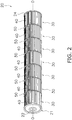
- FIG. 2 shows a schematic structure of the impeller 20 of the cross-flow fan 10.
- the impeller 20 is configured such that, e.g., end plates 21, 24 and a plurality of fan blocks 30 are joined together. In the present embodiment, seven fan blocks 30 are joined together.
- An end plate 21 is arranged on one end of the impeller 20, and a metal rotary shaft 22 is provided along a central axis O.
- Each of the fan blocks 30 comprises a plurality of blades 40 and an annular support plate 50.
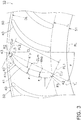
- FIG. 3 shows a plurality of blades 40 secured to the support plate 50 of one of the fan blocks 30.
- the support plate 50 is annular in shape, and has an inner-peripheral end 51 on the inner-peripheral side of the cross-flow fan 10, and an outer-peripheral end 52 on the outer-peripheral side of the cross-flow fan 10.
- Each of the blades 40 is configured from a base portion 41, a leading-edge portion 42, and a trailing-edge portion 43.
- the following cross-sectional shape is employed in common in all of the blades 40 arranged on one of the fan blocks 30, as viewed in a cross-section taken along a plane parallel to the support plate 50. All of the blades 40 arranged on one of the fan blocks 30 are arranged tangent to one inscribed circle IL and one circumscribed circle OL, which are concentric with respect to the inner-peripheral end 51 and the outer-peripheral end 52.
- the leading-edge portion 42 is formed so as to describe a smooth, convex, arc-like shape on the inner-peripheral side of the blade 40, the leading-edge portion 42 having a surface of arc-like cross-section.
- the trailing-edge portion 43 is formed so as to describe a smooth, convex, arc-like shape on the outer-peripheral side of the blade 40, the trailing-edge portion 43 having a surface of arc-like cross-section.
- the base portion 41 is formed between the leading-edge portion 42 and the trailing-edge portion 43, the base portion having a pressure surface 41p and a suction surface 41n.
- the pressure surface 41p of the base portion 41 generates positive pressure
- the suction surface 41n of the base portion 41 generates negative pressure.
- Each of the blades 40 is inclined by an angle ⁇ with respect to a radial line RL intersecting a central axis O of the cross-flow fan 10, the radial line RL extending radially outward from the central axis O.
- the angle of inclination ⁇ of the blade 40 is defined as an angle formed by the radial line RL and a tangent line TL on the inner-peripheral side of the blade 40.
- the pressure surface 41p and suction surface 41n of each of the blades 40 are curved so as to describe smooth arcs that expand toward the outer-peripheral side in cross-section. Because the blades 40 have an angle of inclination ⁇ with respect to radial lines RL, both the center of curvature of the arc of the pressure surface 41p and the center of curvature of the arc of the suction surface 41n are positioned on the inner-peripheral-surface side.
- a chord length CL is the length from a leading end of the leading-edge portion 42 to a trailing end of the trailing-edge portion 43.
- the tangent line TL on the inner-peripheral side of the blade 40 is extended to the inner-peripheral side and outer-peripheral side of the cross-flow fan
- a perpendicular line PL1 is drawn perpendicular to the tangent line TL on the inner-peripheral side of the blade 40 so as to be tangent to the leading-edge portion 42
- a perpendicular line PL2 is drawn perpendicular to the tangent line TL so as to be tangent to the trailing-edge portion 43.
- the length from the perpendicular line PL1 to the perpendicular line PL2 constitutes the chord length CL.
- the blades 40 are configured such that the thickness of the base portion 41; i.e., the distance between the pressure surface 41p and the suction surface 41n varies gradually further from the inner-peripheral side toward the outer-peripheral side. Therefore, there is one location where the thickness of the base portion 41 is greatest.
- the position where the thickness of the base portion 41 is greatest is referred to below as the "position of maximum thickness.”
- the thickness of the base portion 41 is defined as the space between the pressure surface 41p and the suction surface 41n in a direction perpendicular to the pressure surface 41p.
- the position of maximum thickness is indicated at a position at the foot of a perpendicular line drawn from an intermediate position between the pressure surface 41p and the suction surface 41n to the tangent line TL defining the chord length CL.
- the performance of the cross-flow fan 10 is strongly impacted by the cross-sectional shape of the blades 40.
- a cross-sectional shape of the blades 40 that is configured and arranged to elicit excellent performance from the cross-flow fan 10 is described below.
- Each of the blades 40 is formed such that the radius R1 of the arc of the leading-edge portion 42 is greater than the radius R2 of the arc of the trailing-edge portion 43.
- the radius R1 of the arc of the leading-edge portion 42 and the radius R2 of the arc of the trailing-edge portion 43 may be set so as to satisfy the relationship R1/R2 > 1.5, and more preferably to satisfy the relationship R1/R2 > 1.75.
- the position Mxp of maximum thickness of a blade 40 is positioned closer to the leading-edge portion 42 than to the trailing-edge portion 43. Specifically, the position Mxp of maximum thickness may be positioned closer to the leading-edge portion 42 than to an intermediate position CLm along the chord length.
- the blades 40 have a cross-sectional shape such that the relationship ⁇ / ⁇ > ⁇ / ⁇ is satisfied, where the maximum thickness is designated as the maximum thickness ⁇ , the thickness at an intermediate position CLm along the chord length CL is designated as an intermediate thickness ⁇ , and the thickness at an outer-peripheral-side position CL5 set apart from an outer-peripheral end CLp of the blade chord by 5% of the chord length CL is designated as an outer-peripheral-side thickness ⁇ .
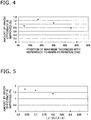
- FIG. 4 shows the relationship between the position Mxp of maximum thickness and the amount by which efficiency is improved.
- the horizontal axis represents a ratio of the chord length CL and the position Mxp of maximum thickness with reference to an inner-peripheral end CLi of the blade chord.
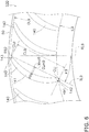
- the vertical axis represents a rate of decrease from a shaft power of blades 140 having a conventional shape as shown in FIG. 6 .
- the rate of decrease is given by the formula (SPo - SPn)/SPo ⁇ 100 (%), where SPo indicates the shaft power required for a conventional cross-flow fan 100 using conventional blades 140 to obtain a prescribed airflow, and SPn indicates the shaft power required for the cross-flow fan 10 using the blades 40 to obtain the same airflow.
- the value of ⁇ / ⁇ )/( ⁇ / ⁇ ) is set to 0.64.
- the radius of an inscribed circle IL9 is approximately equal to the radius of the inscribed circle IL of the cross-flow fan 10
- the radius of a circumscribed circle OL9 is approximately equal to the radius of the circumscribed circle OL of the cross-flow fan 10.
- a chord length CL9 of each of the blades 140 is approximately equal to the chord length CL of each of the blades 40
- the angle of inclination ⁇ 9 is approximately equal to the angle of inclination ⁇ of the blades 40.
- a position Mxp9 of maximum thickness in each of the blades 140 is positioned in the vicinity of an intermediate position CLm9 along the chord length CL9, and is positioned further toward the outer-peripheral side than is the intermediate position CLm9. Due to being configured in such an arrangement, the blades 140 are formed in a crescent-form cross-sectional shape such that the thickness decreases in the same manner toward the inner-peripheral side and the outer-peripheral side.
- the distance from the inner-peripheral end CLi to the position Mxp of maximum thickness is set within a range of 5-45% of the chord length CL. This is because, while an improvement in efficiency in an amount of 0.8-1.3% can be expected when the distance from the inner-peripheral end CLi to the position Mxp of maximum thickness is within a range of 5-45% of the chord length CL, the amount by which efficiency is improved rapidly declines in correspondence with distance from this range.
- FIG. 5 shows the relationship between the amount by which efficiency is improved and the ratio of ( ⁇ / ⁇ ) and ( ⁇ / ⁇ ).
- the amount of improvement shown in FIG. 5 is the rate of decrease from the shaft power of blades for comparison, such as the blades disclosed in Patent Document 1, in which the position of maximum thickness is at a location 4% of a chord length from an inner-peripheral end, the radius of the leading-edge portion is approximately equal to the radius R1 of the leading-edge portion 42 of the blade 40, and the radius of the trailing-edge portion is approximately equal to the radius R2 of the trailing-edge portion 43 of the blade 40.
- the cross-sections of the pressure surface and suction surface between the position of maximum thickness and the trailing-edge portion draw a single arc, and the blades have a cross-sectional shape such that the thickness decreases uniformly.
- the position Mxp of maximum thickness is set to a location 17% from the inner-peripheral end.
- the blades 40 of the cross-flow fan 10 are formed such that the radius R1 of the leading-edge portion 42 is greater than the radius R2 of the trailing-edge portion 43. Additionally, the base portion 41 of each of the blades 40 has a maximum thickness ⁇ at a position Mxp of maximum thickness that is closer to the leading-edge portion 42 than to the trailing-edge portion 43. Additionally, the blades 40 have a thickness ⁇ (an example of a first thickness) at an intermediate position CLm along the blade chord, and a thickness ⁇ (an example of a second thickness) at an outer-peripheral-side position CL5 set apart from the outer-peripheral end CLp of the blade chord by 5% of the chord length.
- the blades 40 are also formed such that the value obtained by dividing the thickness ⁇ located at the intermediate position CLm along the blade chord by the maximum thickness ⁇ is greater than the value obtained by dividing the thickness ⁇ located at the outer-peripheral-side position CL5 by the thickness ⁇ .
- the cross-sectional shape of the blades 40 is formed so as to satisfy the relationship ⁇ / ⁇ > ⁇ / ⁇ .
- the base portion 41 of each of the blades 40 is formed such that the maximum thickness ⁇ is positioned within a range of 5-45% of the chord length CL from the inner-peripheral end. Specifically, the base portion 41 is formed so as to satisfy the relationship 5 ⁇ (distance from inner-peripheral end CLi to position Mxp of maximum thickness)/CL ⁇ 100 ⁇ 45. Additionally, the base portion 41 is configured such that the value of the ratio (( ⁇ / ⁇ )/( ⁇ / ⁇ )) between the value obtained by dividing the thickness ⁇ located at the outer-peripheral-side position CL5 by the thickness ⁇ located at the intermediate position CLm along the blade chord and the value obtained by dividing the thickness ⁇ by the maximum thickness ⁇ is set to 0.85 or less.
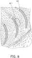
- FIG. 8 is a schematic view of an airflow flowing around a blade 40.
- FIG. 9 is a schematic view of an airflow flowing around a conventional blade 140 (see FIG. 6 ) with reference to the amount by which efficiency is improved in FIG. 4 described above.
- FIG. 10 is schematic view of an airflow flowing around a conventional blade 240 with reference to the amount by which efficiency is improved in FIG. 5 described above.
- the chain double-dash lines indicate blade-side portions where the airflow travels at a relatively slower speed.
- the position Mxp of maximum thickness is located at a position closer to the leading-edge portion 42 than to the intermediate position CLm along the blade chord; i.e., closer to the inner-peripheral side than to the middle of the blade, whereby separation of flow at the suction surface 41n (region Ar1 in FIG. 8 ) from the leading-edge portion 42 of the blade 40 to the trailing-edge portion 43 of the blade 40 is minimized.
- the blade surface at the suction surface has a small curvature because the thickness is smoothly reduced as far as a location near the middle of the blade, it is possible, even if separation of suction surface-side flow occurs, to quickly rejoin the flow at the suction surface and minimize separation to the middle of the blade.
- the conventional blade 140 shown in FIG. 9 because the thickness rapidly decreases from the portion of maximum thickness in the blade 140, separation readily occurs at a region Ar2.
- the flow from the leading-edge portion 42 to the trailing-edge portion 43 is accelerated, turbulence is suppressed, and low-frequency narrowband noise such as N noise is reduced.
- low-frequency narrowband N noise is reduced as shown in FIG. 7 .
- a pronounced effect for reducing N noise is realized by switching from the conventional blade 140 to the blade 40 according to the present embodiment.
Description
- The present invention relates to a blade of a cross-flow fan.
- In indoor units of air conditioners, etc., cross-flow fans are often used in order to blow air. As pertains to a cross-sectional shape of a blade of such a cross-flow fan, an pressure surface of the blade and a suction surface opposite the pressure surface are curved along a direction of rotation of the fan further toward the outer side of the blade from a fan rotary shaft, and, near the center of the blade, are formed in an arc shape set apart from a straight line connecting an inner-peripheral part and an outer-peripheral part of the blade.
- Conventionally, it is known that in blades in which the thickness distribution in the shape of the blade is configured such that a position of maximum thickness is located between a leading edge and a trailing edge, separation of flow at the leading-edge portion occurs, and turbulence readily occurs. In order to improve such an unstable flow when a high load is applied to the cross-flow fan, the blade structure disclosed in Patent Document 1 (Japanese Patent No.
3661579 location 4% of a chord length of blade from an inner-peripheral end, and the thickness decreases from the position of maximum thickness of the blade toward both end parts. However, in the blade structure disclosed inPatent Document 1, because the position of maximum thickness is at alocation 4% of the chord length from an inner side, this position approximately coincides with the inner-peripheral end, and the thickness rapidly decreases toward an outer-peripheral end. Therefore, in some instances, after colliding at the inner-peripheral end, the flow quickly separates off due to the large curvature of the blade surface, and moves downstream in the separated state without rejoining at the outer-peripheral side of the fan on the near side relative to a blade-intermediate position. - In the blade structure disclosed in Patent Document 2 (Japanese Laid-open Patent Application No.
5-79492 Patent Document 2, when a load is applied, a flow vented out from the fan separates off, at a suction surface side having large curvature, in proportion with direction from an inner-peripheral end of the blade toward an outer-peripheral end of the blade, and readily gives rise to turbulence. Therefore, in the blade disclosed inPatent Document 2, an extremely unpleasant, intermittent abnormal noise referred to as "rustling" is readily generated due to the breakdown of a two-dimensional flow. Additionally, because the flow between the blades inPatent Document 2 readily gives rise to turbulence, abnormal noise (low-order narrowband-frequency noise referred to below as "N noise") caused by rotation of the fan increases; this noise is projected at low frequencies, inhibiting a noise-reduction property. Furthermore, when a load is applied to the blade disclosed inPatent Document 2, blowing performance significantly deteriorates, and therefore cooling capacity and heating capacity of the fan decreases. - As described above, in conventional blade structures, separation of flow occurs, reducing the effective inter-blade distance, and the speed of vented-out air increases, correspondingly increasing noise. Additionally, in conventional blade structures, the blade surface cannot be effectively utilized due to the separation of flow, reducing blowing efficiency.
- The problem of the present invention is to obtain a blade of a cross-flow fan with which it is possible to provide a cross-flow fan that is highly efficient and that produces little noise even when high loads are applied.
- The present invention regards a blade of a cross-flow fan according to
claim 1. - In the blade of a cross-flow fan according to the present invention, reduction in noise and increase in efficiency of the cross-flow fan are achieved.
-
-
FIG. 1 is a schematic cross-sectional view of an indoor unit of an air-conditioning apparatus; -
FIG. 2 is a schematic perspective view of an impeller of a cross-flow fan according to an embodiment; -
FIG. 3 is a partial expanded plan view for illustrating a cross-sectional shape of a blade according to the embodiment; -
FIG. 4 is a graph for illustrating a relationship between a position of maximum thickness of the blade and an amount by which efficiency is improved; -
FIG. 5 is a graph for illustrating a relationship between the amount by which efficiency is improved and the ratio (γ/β)/(β/α); -
FIG. 6 is a partial expanded view for illustrating a cross-sectional shape of a conventional blade; -
FIG. 7 is a graph for illustrating a decrease in effect of low-order narrowband-frequency noise; -
FIG. 8 is a schematic view for illustrating an airflow flowing around the blade according to the embodiment; -
FIG. 9 is a schematic view for illustrating an airflow flowing around a conventional blade; and -
FIG. 10 is schematic view for illustrating an airflow flowing around a conventional blade. - A multi-blade fan according to a first embodiment of the present invention is described below through the example of a cross-flow fan installed in an indoor unit of an air-conditioning apparatus.
FIG. 1 is a schematic view of a cross-section of anindoor unit 1 of an air-conditioning apparatus. Theindoor unit 1 comprises amain casing 2, anair filter 3, anindoor heat exchanger 4, across-flow fan 10, avertical flap 5, and ahorizontal flap 6. - As shown in
FIG. 1 , theair filter 3 is arranged downstream from anintake port 2a in a ceiling surface of themain casing 2, theair filter 3 facing theintake port 2a. Theindoor heat exchanger 4 is arranged further downstream from theair filter 3. Theindoor heat exchanger 4 is configured by linking a front-surface-side heat exchanger 4a and a rear-surface-side heat exchanger 4b so as to form an inverse V-shape as viewed from a side surface. The front-surface-side heat exchanger 4a and the rear-surface-side heat exchanger 4b are configured by attaching a plurality of plate fins to a heat-transfer pipe aligned in parallel with one another in a width direction of theindoor unit 1. All indoor air that passes through theintake port 2a and reaches theindoor heat exchanger 4 passes through theair filter 3, and dirt and grit in the indoor air is removed therefrom. The indoor air that has been drawn in through theintake port 2a and passed through theair filter 3 is subjected to heat-exchange and air-conditioning when passing between the plate fins of the front-surface-side heat exchanger 4a and rear-surface-side heat exchanger 4b. - The
cross-flow fan 10, which is substantially cylindrical in shape, is provided downstream from theindoor heat exchanger 4, thecross-flow fan 10 extending longitudinally along a width direction of themain casing 2. Thecross-flow fan 10 is arranged in parallel with theindoor heat exchanger 4. Thecross-flow fan 10 comprises animpeller 20 arranged in a space surrounded so as to be sandwiched in the inverse V-shape of theindoor heat exchanger 4, and a fan motor (not shown) configured and arranged to drive theimpeller 20. Thecross-flow fan 10 generates an airflow from theindoor heat exchanger 4 toward avent 2b by the rotation of theimpeller 20 in a direction A1 shown by arrows inFIG. 1 (i.e., clockwise). Specifically, thecross-flow fan 10 is a transverse fan, configured such that the airflow passes transversely across thecross-flow fan 10. - A rear-surface side of a vent passage linked to the
vent 2b downstream from thecross-flow fan 10 is configured from ascroll member 2c. A lower end of thescroll member 2c is linked to a lower edge of an opening of thevent 2b. In order to guide indoor air, which is vented out from thecross-flow fan 10, smoothly and silently to thevent 2b, a guide surface of thescroll member 2c has a smooth curved shape having a center of curvature on the cross-flow-fan 10 side as viewed in cross-section. Atongue part 2d is formed on the front-surface side of thecross-flow fan 10, and an upper surface of the vent passage that is continuous from thetongue part 2d is linked to an upper edge of thevent 2b. A direction in which the airflow is vented out from thevent 2b is adjusted using thevertical flap 5 andhorizontal flap 6. -
FIG. 2 shows a schematic structure of theimpeller 20 of thecross-flow fan 10. Theimpeller 20 is configured such that, e.g.,end plates fan blocks 30 are joined together. In the present embodiment, sevenfan blocks 30 are joined together. Anend plate 21 is arranged on one end of theimpeller 20, and a metalrotary shaft 22 is provided along a central axis O. Each of thefan blocks 30 comprises a plurality ofblades 40 and anannular support plate 50. -
FIG. 3 shows a plurality ofblades 40 secured to thesupport plate 50 of one of thefan blocks 30. Thesupport plate 50 is annular in shape, and has an inner-peripheral end 51 on the inner-peripheral side of thecross-flow fan 10, and an outer-peripheral end 52 on the outer-peripheral side of thecross-flow fan 10. Each of theblades 40 is configured from abase portion 41, a leading-edge portion 42, and a trailing-edge portion 43. The following cross-sectional shape is employed in common in all of theblades 40 arranged on one of thefan blocks 30, as viewed in a cross-section taken along a plane parallel to thesupport plate 50. All of theblades 40 arranged on one of thefan blocks 30 are arranged tangent to one inscribed circle IL and one circumscribed circle OL, which are concentric with respect to the inner-peripheral end 51 and the outer-peripheral end 52. - The leading-
edge portion 42 is formed so as to describe a smooth, convex, arc-like shape on the inner-peripheral side of theblade 40, the leading-edge portion 42 having a surface of arc-like cross-section. The trailing-edge portion 43 is formed so as to describe a smooth, convex, arc-like shape on the outer-peripheral side of theblade 40, the trailing-edge portion 43 having a surface of arc-like cross-section. Thebase portion 41 is formed between the leading-edge portion 42 and the trailing-edge portion 43, the base portion having apressure surface 41p and asuction surface 41n. Thepressure surface 41p of thebase portion 41 generates positive pressure, and thesuction surface 41n of thebase portion 41 generates negative pressure. - Each of the
blades 40 is inclined by an angle θ with respect to a radial line RL intersecting a central axis O of thecross-flow fan 10, the radial line RL extending radially outward from the central axis O. The angle of inclination θ of theblade 40 is defined as an angle formed by the radial line RL and a tangent line TL on the inner-peripheral side of theblade 40. - The
pressure surface 41p andsuction surface 41n of each of theblades 40 are curved so as to describe smooth arcs that expand toward the outer-peripheral side in cross-section. Because theblades 40 have an angle of inclination θ with respect to radial lines RL, both the center of curvature of the arc of thepressure surface 41p and the center of curvature of the arc of thesuction surface 41n are positioned on the inner-peripheral-surface side. - A chord length CL is the length from a leading end of the leading-
edge portion 42 to a trailing end of the trailing-edge portion 43. Specifically, the tangent line TL on the inner-peripheral side of theblade 40 is extended to the inner-peripheral side and outer-peripheral side of the cross-flow fan, a perpendicular line PL1 is drawn perpendicular to the tangent line TL on the inner-peripheral side of theblade 40 so as to be tangent to the leading-edge portion 42, and a perpendicular line PL2 is drawn perpendicular to the tangent line TL so as to be tangent to the trailing-edge portion 43. The length from the perpendicular line PL1 to the perpendicular line PL2 constitutes the chord length CL. - The
blades 40 are configured such that the thickness of thebase portion 41; i.e., the distance between thepressure surface 41p and thesuction surface 41n varies gradually further from the inner-peripheral side toward the outer-peripheral side. Therefore, there is one location where the thickness of thebase portion 41 is greatest. The position where the thickness of thebase portion 41 is greatest is referred to below as the "position of maximum thickness." In the present description, the thickness of thebase portion 41 is defined as the space between thepressure surface 41p and thesuction surface 41n in a direction perpendicular to thepressure surface 41p. The position of maximum thickness is indicated at a position at the foot of a perpendicular line drawn from an intermediate position between thepressure surface 41p and thesuction surface 41n to the tangent line TL defining the chord length CL. - The performance of the
cross-flow fan 10 is strongly impacted by the cross-sectional shape of theblades 40. A cross-sectional shape of theblades 40 that is configured and arranged to elicit excellent performance from thecross-flow fan 10 is described below. Each of theblades 40 is formed such that the radius R1 of the arc of the leading-edge portion 42 is greater than the radius R2 of the arc of the trailing-edge portion 43. For example, the radius R1 of the arc of the leading-edge portion 42 and the radius R2 of the arc of the trailing-edge portion 43 may be set so as to satisfy the relationship R1/R2 > 1.5, and more preferably to satisfy the relationship R1/R2 > 1.75. The position Mxp of maximum thickness of ablade 40 is positioned closer to the leading-edge portion 42 than to the trailing-edge portion 43. Specifically, the position Mxp of maximum thickness may be positioned closer to the leading-edge portion 42 than to an intermediate position CLm along the chord length. Theblades 40 have a cross-sectional shape such that the relationship β/α > γ/β is satisfied, where the maximum thickness is designated as the maximum thickness α, the thickness at an intermediate position CLm along the chord length CL is designated as an intermediate thickness β, and the thickness at an outer-peripheral-side position CL5 set apart from an outer-peripheral end CLp of the blade chord by 5% of the chord length CL is designated as an outer-peripheral-side thickness γ. -
FIG. 4 shows the relationship between the position Mxp of maximum thickness and the amount by which efficiency is improved. The horizontal axis represents a ratio of the chord length CL and the position Mxp of maximum thickness with reference to an inner-peripheral end CLi of the blade chord. The vertical axis represents a rate of decrease from a shaft power ofblades 140 having a conventional shape as shown inFIG. 6 . Specifically, the rate of decrease is given by the formula (SPo - SPn)/SPo × 100 (%), where SPo indicates the shaft power required for a conventionalcross-flow fan 100 usingconventional blades 140 to obtain a prescribed airflow, and SPn indicates the shaft power required for thecross-flow fan 10 using theblades 40 to obtain the same airflow. In theblades 40 shown inFIG. 3 , the value of γ/β)/(β/α) is set to 0.64. - In the conventional
cross-flow fan 100 shown inFIG. 6 , the radius of an inscribed circle IL9 is approximately equal to the radius of the inscribed circle IL of thecross-flow fan 10, and the radius of a circumscribed circle OL9 is approximately equal to the radius of the circumscribed circle OL of thecross-flow fan 10. Additionally, a chord length CL9 of each of theblades 140 is approximately equal to the chord length CL of each of theblades 40, and the angle of inclination θ9 (an angle formed by a radial line RL9 and a tangent line TL9 on the inner-peripheral side of the blades 140) of theblades 140 is approximately equal to the angle of inclination θ of theblades 40. In theblades 140 shown inFIG. 6 , the radius R91 of a leading-edge portion 142 and the radius R92 of a trailing-edge portion 143 are approximately the same, thereby constituting a point of difference from theblades 40 shown inFIG. 3 . Additionally, a position Mxp9 of maximum thickness in each of theblades 140 is positioned in the vicinity of an intermediate position CLm9 along the chord length CL9, and is positioned further toward the outer-peripheral side than is the intermediate position CLm9. Due to being configured in such an arrangement, theblades 140 are formed in a crescent-form cross-sectional shape such that the thickness decreases in the same manner toward the inner-peripheral side and the outer-peripheral side. - As shown in
FIG. 4 , it is apparent that the distance from the inner-peripheral end CLi to the position Mxp of maximum thickness is set within a range of 5-45% of the chord length CL. This is because, while an improvement in efficiency in an amount of 0.8-1.3% can be expected when the distance from the inner-peripheral end CLi to the position Mxp of maximum thickness is within a range of 5-45% of the chord length CL, the amount by which efficiency is improved rapidly declines in correspondence with distance from this range. -
FIG. 5 shows the relationship between the amount by which efficiency is improved and the ratio of (γ/β) and (β/α). The amount of improvement shown inFIG. 5 is the rate of decrease from the shaft power of blades for comparison, such as the blades disclosed inPatent Document 1, in which the position of maximum thickness is at alocation 4% of a chord length from an inner-peripheral end, the radius of the leading-edge portion is approximately equal to the radius R1 of the leading-edge portion 42 of theblade 40, and the radius of the trailing-edge portion is approximately equal to the radius R2 of the trailing-edge portion 43 of theblade 40. In the blades for comparison, the cross-sections of the pressure surface and suction surface between the position of maximum thickness and the trailing-edge portion draw a single arc, and the blades have a cross-sectional shape such that the thickness decreases uniformly. In theblades 40 shown inFIG. 3 , the position Mxp of maximum thickness is set to a location 17% from the inner-peripheral end. - As shall be apparent from
FIG. 5 , when (γ/β)/(β/α) is set to 0.85 or less, the amount by which efficiency is improved reaches a value greater than 1%. Thus, according to the present invention (γ/β)/(β/α) is set to 0.85 or less. - As described above, according to the present invention the
blades 40 of thecross-flow fan 10 are formed such that the radius R1 of the leading-edge portion 42 is greater than the radius R2 of the trailing-edge portion 43. Additionally, thebase portion 41 of each of theblades 40 has a maximum thickness α at a position Mxp of maximum thickness that is closer to the leading-edge portion 42 than to the trailing-edge portion 43. Additionally, theblades 40 have a thickness β (an example of a first thickness) at an intermediate position CLm along the blade chord, and a thickness γ (an example of a second thickness) at an outer-peripheral-side position CL5 set apart from the outer-peripheral end CLp of the blade chord by 5% of the chord length. Theblades 40 are also formed such that the value obtained by dividing the thickness β located at the intermediate position CLm along the blade chord by the maximum thickness α is greater than the value obtained by dividing the thickness γ located at the outer-peripheral-side position CL5 by the thickness β. Specifically, the cross-sectional shape of theblades 40 is formed so as to satisfy the relationship β/α > γ/β. - The
base portion 41 of each of theblades 40 is formed such that the maximum thickness α is positioned within a range of 5-45% of the chord length CL from the inner-peripheral end. Specifically, thebase portion 41 is formed so as to satisfy therelationship 5 ≤ (distance from inner-peripheral end CLi to position Mxp of maximum thickness)/CL × 100 ≤ 45. Additionally, thebase portion 41 is configured such that the value of the ratio ((γ/β)/(β/α)) between the value obtained by dividing the thickness γ located at the outer-peripheral-side position CL5 by the thickness β located at the intermediate position CLm along the blade chord and the value obtained by dividing the thickness β by the maximum thickness α is set to 0.85 or less. -
FIG. 8 is a schematic view of an airflow flowing around ablade 40.FIG. 9 is a schematic view of an airflow flowing around a conventional blade 140 (seeFIG. 6 ) with reference to the amount by which efficiency is improved inFIG. 4 described above.FIG. 10 is schematic view of an airflow flowing around aconventional blade 240 with reference to the amount by which efficiency is improved inFIG. 5 described above. InFIGS. 8 ,9 , and10 , the chain double-dash lines indicate blade-side portions where the airflow travels at a relatively slower speed. - As a result of the
blades 40 having the shape described above, as pertains to the flow in the vicinity of theblades 40 when air is vented, the position Mxp of maximum thickness is located at a position closer to the leading-edge portion 42 than to the intermediate position CLm along the blade chord; i.e., closer to the inner-peripheral side than to the middle of the blade, whereby separation of flow at thesuction surface 41n (region Ar1 inFIG. 8 ) from the leading-edge portion 42 of theblade 40 to the trailing-edge portion 43 of theblade 40 is minimized. Furthermore, since the blade surface at the suction surface has a small curvature because the thickness is smoothly reduced as far as a location near the middle of the blade, it is possible, even if separation of suction surface-side flow occurs, to quickly rejoin the flow at the suction surface and minimize separation to the middle of the blade. However, in theconventional blade 140 shown inFIG. 9 , because the thickness rapidly decreases from the portion of maximum thickness in theblade 140, separation readily occurs at a region Ar2. In theconventional blade 240 shown inFIG. 10 , because the portion of maximum thickness in theblade 240 is close to the leading-edge portion, and the thickness begins decreasing from the portion of maximum thickness, there is a high possibility that, after colliding with the leading-edge portion, the flow will quickly separate off at the region Ar3 due to the large curvature of the blade surface, and move downstream in the separated state without rejoining at the outer-peripheral side relative to a blade-intermediate position. - In the
blade 40 described above, the flow from the leading-edge portion 42 to the trailing-edge portion 43 is accelerated, turbulence is suppressed, and low-frequency narrowband noise such as N noise is reduced. Specifically, as shall be apparent from comparing theblades 40 shown inFIG. 3 with theblades 140 shown inFIG. 6 , low-frequency narrowband N noise is reduced as shown inFIG. 7 . In particular, in the portions surrounded by chain double-dash lines inFIG. 7 , a pronounced effect for reducing N noise is realized by switching from theconventional blade 140 to theblade 40 according to the present embodiment. -
- 10
- Cross-flow fan
- 30
- Fan block
- 40
- Blade
- 41
- Base portion
- 41p
- Pressure surface
- 41n
- Suction surface
- 42
- Leading-edge portion
- 43
- Trailing-edge portion
- 50
- Support plate
-
- Patent Document 1: Japanese Patent No.
3661579 - Patent Document 2: Japanese Laid-open Patent Application No.
5-79492
Claims (1)
- A blade of a cross-flow fan comprising:a leading-edge portion (42) arranged on the inner-peripheral side of the cross-flow fan (10), the leading-edge portion being formed in an arc-like shape;a trailing-edge portion (43) arranged in the outer-peripheral side of the cross-flow fan, the trailing-edge portion being formed in an arc-like shape; anda base portion (41) formed between the leading-edge portion and the trailing-edge portion, the base portion having a pressure surface (41p) configured and arranged to generate positive pressure, and a suction surface (41n) configured and arranged to generate negative pressure;the leading-edge portion and the trailing-edge portion being formed such that the radius of the leading-edge portion is greater than the radius of the trailing-edge portion;wherein the pressure surface (41p) and suction surface (41n) of the blade (40) are curved so as to describe smooth arcs that expand toward the outer-peripheral side in cross-section;wherein the distance between the pressure surface (41p) and the suction surface (41n) gradually varies from the inner-peripheral side toward the outer-peripheral side; andthe base portion being formed so as to have a maximum thickness at a position of maximum thickness, a first thickness at an intermediate position on a blade chord, and a second thickness at a position set apart from an outer-peripheral end of the blade chord by 5% of the chord length;whereinthe base portion is configured such that the position of maximum thickness is positioned within a range of 5-45% of the chord length from an inner-peripheral end; andwhereinthe base portion is configured such that the value of the ratio between the value obtained by dividing the second thickness by the first thickness and the value obtained by dividing the first thickness by the maximum thickness is set to 0.85 or less.
Applications Claiming Priority (2)
| Application Number | Priority Date | Filing Date | Title |
|---|---|---|---|
| JP2013272151A JP5825339B2 (en) | 2013-12-27 | 2013-12-27 | Cross flow fan wings |
| PCT/JP2014/083543 WO2015098689A1 (en) | 2013-12-27 | 2014-12-18 | Cross-flow fan blade |
Publications (3)
| Publication Number | Publication Date |
|---|---|
| EP3078860A1 EP3078860A1 (en) | 2016-10-12 |
| EP3078860A4 EP3078860A4 (en) | 2017-01-11 |
| EP3078860B1 true EP3078860B1 (en) | 2019-02-27 |
Family
ID=53478550
Family Applications (1)
| Application Number | Title | Priority Date | Filing Date |
|---|---|---|---|
| EP14875882.4A Active EP3078860B1 (en) | 2013-12-27 | 2014-12-18 | Cross-flow fan blade |
Country Status (9)
| Country | Link |
|---|---|
| US (1) | US10690142B2 (en) |
| EP (1) | EP3078860B1 (en) |
| JP (1) | JP5825339B2 (en) |
| CN (1) | CN105849417B (en) |
| AU (1) | AU2014371353B2 (en) |
| BR (1) | BR112016014694B1 (en) |
| ES (1) | ES2727422T3 (en) |
| MY (1) | MY183273A (en) |
| WO (1) | WO2015098689A1 (en) |
Families Citing this family (4)
| Publication number | Priority date | Publication date | Assignee | Title |
|---|---|---|---|---|
| JP6210104B2 (en) * | 2015-10-30 | 2017-10-11 | ダイキン工業株式会社 | Cross flow fan |
| CN108180166A (en) * | 2017-12-26 | 2018-06-19 | 博耐尔汽车电气系统有限公司 | A kind of air conditioner motor fan impeller structure |
| KR102096160B1 (en) * | 2018-03-29 | 2020-04-01 | 주식회사 원진일렉트로닉스 | Dust centrifugal fan of blower |
| JP6852768B1 (en) | 2019-09-30 | 2021-03-31 | ダイキン工業株式会社 | Cross-flow fan wings, cross-flow fan and air-conditioning indoor unit |
Family Cites Families (15)
| Publication number | Priority date | Publication date | Assignee | Title |
|---|---|---|---|---|
| US3952971A (en) * | 1971-11-09 | 1976-04-27 | The United States Of America As Represented By The Administrator Of The National Aeronautics And Space Administration | Airfoil shape for flight at subsonic speeds |
| JPH0579492A (en) | 1991-09-20 | 1993-03-30 | Daikin Ind Ltd | Lateral flow fan |
| JP3107711B2 (en) * | 1994-08-09 | 2000-11-13 | 株式会社東芝 | Cross flow fan |
| JP3504363B2 (en) * | 1995-01-30 | 2004-03-08 | 三菱電機株式会社 | Cross-flow blower impeller |
| US6565334B1 (en) * | 1998-07-20 | 2003-05-20 | Phillip James Bradbury | Axial flow fan having counter-rotating dual impeller blade arrangement |
| US6261051B1 (en) * | 1998-09-02 | 2001-07-17 | Gordon A. Kolacny | Fan duct combination unit |
| JP3661579B2 (en) | 1999-10-22 | 2005-06-15 | 松下電器産業株式会社 | Air conditioner indoor unit |
| JP3866897B2 (en) * | 2000-03-21 | 2007-01-10 | 三菱電機株式会社 | Cross-flow blower and air conditioner |
| JP4583095B2 (en) * | 2004-07-27 | 2010-11-17 | 東芝キヤリア株式会社 | Cross flow fan |
| FR2898943B1 (en) * | 2006-03-23 | 2012-08-31 | Valeo Systemes Thermiques | FAN PROPELLER, ESPECIALLY FOR AUTOMOTIVE VEHICLES |
| ES2294927B1 (en) * | 2006-05-31 | 2009-02-16 | Gamesa Eolica, S.A. | AIRLINER SHOVEL WITH DIVERGING OUTPUT EDGE. |
| JP2009036138A (en) | 2007-08-03 | 2009-02-19 | Hitachi Appliances Inc | Air conditioner |
| CN103089661B (en) * | 2011-11-04 | 2015-04-01 | 上海交通大学 | Cross flow fan |
| WO2013150569A1 (en) | 2012-04-06 | 2013-10-10 | 三菱電機株式会社 | Indoor unit for air conditioning device |
| CN202991621U (en) * | 2012-07-16 | 2013-06-12 | 广东美的暖通设备有限公司 | Wind wheel vane, tubular wind wheel and air conditioner |
-
2013
- 2013-12-27 JP JP2013272151A patent/JP5825339B2/en active Active
-
2014
- 2014-12-18 AU AU2014371353A patent/AU2014371353B2/en active Active
- 2014-12-18 CN CN201480070915.8A patent/CN105849417B/en active Active
- 2014-12-18 BR BR112016014694-8A patent/BR112016014694B1/en active IP Right Grant
- 2014-12-18 US US15/107,434 patent/US10690142B2/en active Active
- 2014-12-18 ES ES14875882T patent/ES2727422T3/en active Active
- 2014-12-18 WO PCT/JP2014/083543 patent/WO2015098689A1/en active Application Filing
- 2014-12-18 MY MYPI2016702106A patent/MY183273A/en unknown
- 2014-12-18 EP EP14875882.4A patent/EP3078860B1/en active Active
Non-Patent Citations (1)
| Title |
|---|
| None * |
Also Published As
| Publication number | Publication date |
|---|---|
| JP5825339B2 (en) | 2015-12-02 |
| US10690142B2 (en) | 2020-06-23 |
| BR112016014694A2 (en) | 2017-08-08 |
| ES2727422T3 (en) | 2019-10-16 |
| CN105849417A (en) | 2016-08-10 |
| WO2015098689A1 (en) | 2015-07-02 |
| BR112016014694B1 (en) | 2022-05-17 |
| US20170002827A1 (en) | 2017-01-05 |
| JP2015124766A (en) | 2015-07-06 |
| EP3078860A1 (en) | 2016-10-12 |
| MY183273A (en) | 2021-02-18 |
| AU2014371353B2 (en) | 2017-07-27 |
| CN105849417B (en) | 2017-12-01 |
| AU2014371353A1 (en) | 2016-08-04 |
| EP3078860A4 (en) | 2017-01-11 |
Similar Documents
| Publication | Publication Date | Title |
|---|---|---|
| US9995303B2 (en) | Air conditioner | |
| US9267511B2 (en) | Turbofan and indoor unit of air-conditioning apparatus including the same | |
| US9829004B2 (en) | Turbo fan and air conditioner | |
| US20110023526A1 (en) | Centrifugal fan | |
| US10052931B2 (en) | Outdoor cooling unit in vehicle air-conditioning apparatus | |
| EP3078860B1 (en) | Cross-flow fan blade | |
| KR20080104169A (en) | Multi-blade fan | |
| EP2957443B1 (en) | Outdoor cooling unit for air conditioning device for vehicle | |
| KR20050005086A (en) | Stator of Axial flow fan shroud | |
| EP2530331B1 (en) | Axial fan assembly for a vehicle cooling system | |
| US10400605B2 (en) | Turbofan and indoor unit for air conditioning apparatus | |
| US20100092286A1 (en) | Axial flow fan | |
| US9303649B2 (en) | Cross flow fan and air-conditioning apparatus including same | |
| EP3043077A1 (en) | Propeller fan, air-blowing device, and outdoor unit | |
| JP6611676B2 (en) | Outdoor unit for blower and refrigeration cycle equipment | |
| JP2017180094A (en) | Blower fan, and blower unit using the former | |
| US20150204345A1 (en) | Propeller fan | |
| CN114502842B (en) | Blade of cross flow fan, cross flow fan and air conditioner indoor unit | |
| CN210921589U (en) | Centrifugal wind wheel and air conditioner | |
| EP3015775B1 (en) | Indoor unit for air-conditioning device | |
| WO2020026373A1 (en) | Cross-flow fan and air conditioner |
Legal Events
| Date | Code | Title | Description |
|---|---|---|---|
| PUAI | Public reference made under article 153(3) epc to a published international application that has entered the european phase |
Free format text: ORIGINAL CODE: 0009012 |
|
| 17P | Request for examination filed |
Effective date: 20160706 |
|
| AK | Designated contracting states |
Kind code of ref document: A1 Designated state(s): AL AT BE BG CH CY CZ DE DK EE ES FI FR GB GR HR HU IE IS IT LI LT LU LV MC MK MT NL NO PL PT RO RS SE SI SK SM TR |
|
| AX | Request for extension of the european patent |
Extension state: BA ME |
|
| A4 | Supplementary search report drawn up and despatched |
Effective date: 20161209 |
|
| RIC1 | Information provided on ipc code assigned before grant |
Ipc: F04D 17/04 20060101AFI20161205BHEP Ipc: F04D 29/30 20060101ALI20161205BHEP Ipc: F04D 29/28 20060101ALI20161205BHEP Ipc: F04D 29/66 20060101ALI20161205BHEP Ipc: F24F 1/00 20110101ALI20161205BHEP |
|
| DAX | Request for extension of the european patent (deleted) | ||
| GRAP | Despatch of communication of intention to grant a patent |
Free format text: ORIGINAL CODE: EPIDOSNIGR1 |
|
| STAA | Information on the status of an ep patent application or granted ep patent |
Free format text: STATUS: GRANT OF PATENT IS INTENDED |
|
| INTG | Intention to grant announced |
Effective date: 20181012 |
|
| GRAS | Grant fee paid |
Free format text: ORIGINAL CODE: EPIDOSNIGR3 |
|
| GRAA | (expected) grant |
Free format text: ORIGINAL CODE: 0009210 |
|
| STAA | Information on the status of an ep patent application or granted ep patent |
Free format text: STATUS: THE PATENT HAS BEEN GRANTED |
|
| AK | Designated contracting states |
Kind code of ref document: B1 Designated state(s): AL AT BE BG CH CY CZ DE DK EE ES FI FR GB GR HR HU IE IS IT LI LT LU LV MC MK MT NL NO PL PT RO RS SE SI SK SM TR |
|
| REG | Reference to a national code |
Ref country code: GB Ref legal event code: FG4D |
|
| REG | Reference to a national code |
Ref country code: CH Ref legal event code: EP |
|
| REG | Reference to a national code |
Ref country code: AT Ref legal event code: REF Ref document number: 1101771 Country of ref document: AT Kind code of ref document: T Effective date: 20190315 |
|
| REG | Reference to a national code |
Ref country code: IE Ref legal event code: FG4D |
|
| REG | Reference to a national code |
Ref country code: DE Ref legal event code: R096 Ref document number: 602014042108 Country of ref document: DE |
|
| REG | Reference to a national code |
Ref country code: NL Ref legal event code: MP Effective date: 20190227 |
|
| REG | Reference to a national code |
Ref country code: LT Ref legal event code: MG4D |
|
| PG25 | Lapsed in a contracting state [announced via postgrant information from national office to epo] |
Ref country code: NL Free format text: LAPSE BECAUSE OF FAILURE TO SUBMIT A TRANSLATION OF THE DESCRIPTION OR TO PAY THE FEE WITHIN THE PRESCRIBED TIME-LIMIT Effective date: 20190227 Ref country code: LT Free format text: LAPSE BECAUSE OF FAILURE TO SUBMIT A TRANSLATION OF THE DESCRIPTION OR TO PAY THE FEE WITHIN THE PRESCRIBED TIME-LIMIT Effective date: 20190227 Ref country code: NO Free format text: LAPSE BECAUSE OF FAILURE TO SUBMIT A TRANSLATION OF THE DESCRIPTION OR TO PAY THE FEE WITHIN THE PRESCRIBED TIME-LIMIT Effective date: 20190527 Ref country code: PT Free format text: LAPSE BECAUSE OF FAILURE TO SUBMIT A TRANSLATION OF THE DESCRIPTION OR TO PAY THE FEE WITHIN THE PRESCRIBED TIME-LIMIT Effective date: 20190627 Ref country code: FI Free format text: LAPSE BECAUSE OF FAILURE TO SUBMIT A TRANSLATION OF THE DESCRIPTION OR TO PAY THE FEE WITHIN THE PRESCRIBED TIME-LIMIT Effective date: 20190227 Ref country code: SE Free format text: LAPSE BECAUSE OF FAILURE TO SUBMIT A TRANSLATION OF THE DESCRIPTION OR TO PAY THE FEE WITHIN THE PRESCRIBED TIME-LIMIT Effective date: 20190227 |
|
| PG25 | Lapsed in a contracting state [announced via postgrant information from national office to epo] |
Ref country code: RS Free format text: LAPSE BECAUSE OF FAILURE TO SUBMIT A TRANSLATION OF THE DESCRIPTION OR TO PAY THE FEE WITHIN THE PRESCRIBED TIME-LIMIT Effective date: 20190227 Ref country code: GR Free format text: LAPSE BECAUSE OF FAILURE TO SUBMIT A TRANSLATION OF THE DESCRIPTION OR TO PAY THE FEE WITHIN THE PRESCRIBED TIME-LIMIT Effective date: 20190528 Ref country code: HR Free format text: LAPSE BECAUSE OF FAILURE TO SUBMIT A TRANSLATION OF THE DESCRIPTION OR TO PAY THE FEE WITHIN THE PRESCRIBED TIME-LIMIT Effective date: 20190227 Ref country code: BG Free format text: LAPSE BECAUSE OF FAILURE TO SUBMIT A TRANSLATION OF THE DESCRIPTION OR TO PAY THE FEE WITHIN THE PRESCRIBED TIME-LIMIT Effective date: 20190527 Ref country code: LV Free format text: LAPSE BECAUSE OF FAILURE TO SUBMIT A TRANSLATION OF THE DESCRIPTION OR TO PAY THE FEE WITHIN THE PRESCRIBED TIME-LIMIT Effective date: 20190227 Ref country code: IS Free format text: LAPSE BECAUSE OF FAILURE TO SUBMIT A TRANSLATION OF THE DESCRIPTION OR TO PAY THE FEE WITHIN THE PRESCRIBED TIME-LIMIT Effective date: 20190627 |
|
| REG | Reference to a national code |
Ref country code: AT Ref legal event code: MK05 Ref document number: 1101771 Country of ref document: AT Kind code of ref document: T Effective date: 20190227 |
|
| REG | Reference to a national code |
Ref country code: ES Ref legal event code: FG2A Ref document number: 2727422 Country of ref document: ES Kind code of ref document: T3 Effective date: 20191016 |
|
| PG25 | Lapsed in a contracting state [announced via postgrant information from national office to epo] |
Ref country code: SK Free format text: LAPSE BECAUSE OF FAILURE TO SUBMIT A TRANSLATION OF THE DESCRIPTION OR TO PAY THE FEE WITHIN THE PRESCRIBED TIME-LIMIT Effective date: 20190227 Ref country code: RO Free format text: LAPSE BECAUSE OF FAILURE TO SUBMIT A TRANSLATION OF THE DESCRIPTION OR TO PAY THE FEE WITHIN THE PRESCRIBED TIME-LIMIT Effective date: 20190227 Ref country code: CZ Free format text: LAPSE BECAUSE OF FAILURE TO SUBMIT A TRANSLATION OF THE DESCRIPTION OR TO PAY THE FEE WITHIN THE PRESCRIBED TIME-LIMIT Effective date: 20190227 Ref country code: AL Free format text: LAPSE BECAUSE OF FAILURE TO SUBMIT A TRANSLATION OF THE DESCRIPTION OR TO PAY THE FEE WITHIN THE PRESCRIBED TIME-LIMIT Effective date: 20190227 Ref country code: DK Free format text: LAPSE BECAUSE OF FAILURE TO SUBMIT A TRANSLATION OF THE DESCRIPTION OR TO PAY THE FEE WITHIN THE PRESCRIBED TIME-LIMIT Effective date: 20190227 Ref country code: EE Free format text: LAPSE BECAUSE OF FAILURE TO SUBMIT A TRANSLATION OF THE DESCRIPTION OR TO PAY THE FEE WITHIN THE PRESCRIBED TIME-LIMIT Effective date: 20190227 |
|
| REG | Reference to a national code |
Ref country code: DE Ref legal event code: R097 Ref document number: 602014042108 Country of ref document: DE |
|
| PG25 | Lapsed in a contracting state [announced via postgrant information from national office to epo] |
Ref country code: PL Free format text: LAPSE BECAUSE OF FAILURE TO SUBMIT A TRANSLATION OF THE DESCRIPTION OR TO PAY THE FEE WITHIN THE PRESCRIBED TIME-LIMIT Effective date: 20190227 Ref country code: SM Free format text: LAPSE BECAUSE OF FAILURE TO SUBMIT A TRANSLATION OF THE DESCRIPTION OR TO PAY THE FEE WITHIN THE PRESCRIBED TIME-LIMIT Effective date: 20190227 |
|
| PG25 | Lapsed in a contracting state [announced via postgrant information from national office to epo] |
Ref country code: AT Free format text: LAPSE BECAUSE OF FAILURE TO SUBMIT A TRANSLATION OF THE DESCRIPTION OR TO PAY THE FEE WITHIN THE PRESCRIBED TIME-LIMIT Effective date: 20190227 |
|
| PLBE | No opposition filed within time limit |
Free format text: ORIGINAL CODE: 0009261 |
|
| STAA | Information on the status of an ep patent application or granted ep patent |
Free format text: STATUS: NO OPPOSITION FILED WITHIN TIME LIMIT |
|
| 26N | No opposition filed |
Effective date: 20191128 |
|
| PG25 | Lapsed in a contracting state [announced via postgrant information from national office to epo] |
Ref country code: SI Free format text: LAPSE BECAUSE OF FAILURE TO SUBMIT A TRANSLATION OF THE DESCRIPTION OR TO PAY THE FEE WITHIN THE PRESCRIBED TIME-LIMIT Effective date: 20190227 |
|
| PG25 | Lapsed in a contracting state [announced via postgrant information from national office to epo] |
Ref country code: TR Free format text: LAPSE BECAUSE OF FAILURE TO SUBMIT A TRANSLATION OF THE DESCRIPTION OR TO PAY THE FEE WITHIN THE PRESCRIBED TIME-LIMIT Effective date: 20190227 |
|
| REG | Reference to a national code |
Ref country code: CH Ref legal event code: PL |
|
| REG | Reference to a national code |
Ref country code: BE Ref legal event code: MM Effective date: 20191231 |
|
| PG25 | Lapsed in a contracting state [announced via postgrant information from national office to epo] |
Ref country code: MC Free format text: LAPSE BECAUSE OF FAILURE TO SUBMIT A TRANSLATION OF THE DESCRIPTION OR TO PAY THE FEE WITHIN THE PRESCRIBED TIME-LIMIT Effective date: 20190227 |
|
| PG25 | Lapsed in a contracting state [announced via postgrant information from national office to epo] |
Ref country code: LU Free format text: LAPSE BECAUSE OF NON-PAYMENT OF DUE FEES Effective date: 20191218 Ref country code: IE Free format text: LAPSE BECAUSE OF NON-PAYMENT OF DUE FEES Effective date: 20191218 |
|
| PG25 | Lapsed in a contracting state [announced via postgrant information from national office to epo] |
Ref country code: CH Free format text: LAPSE BECAUSE OF NON-PAYMENT OF DUE FEES Effective date: 20191231 Ref country code: BE Free format text: LAPSE BECAUSE OF NON-PAYMENT OF DUE FEES Effective date: 20191231 Ref country code: LI Free format text: LAPSE BECAUSE OF NON-PAYMENT OF DUE FEES Effective date: 20191231 |
|
| PG25 | Lapsed in a contracting state [announced via postgrant information from national office to epo] |
Ref country code: CY Free format text: LAPSE BECAUSE OF FAILURE TO SUBMIT A TRANSLATION OF THE DESCRIPTION OR TO PAY THE FEE WITHIN THE PRESCRIBED TIME-LIMIT Effective date: 20190227 |
|
| PG25 | Lapsed in a contracting state [announced via postgrant information from national office to epo] |
Ref country code: HU Free format text: LAPSE BECAUSE OF FAILURE TO SUBMIT A TRANSLATION OF THE DESCRIPTION OR TO PAY THE FEE WITHIN THE PRESCRIBED TIME-LIMIT; INVALID AB INITIO Effective date: 20141218 Ref country code: MT Free format text: LAPSE BECAUSE OF FAILURE TO SUBMIT A TRANSLATION OF THE DESCRIPTION OR TO PAY THE FEE WITHIN THE PRESCRIBED TIME-LIMIT Effective date: 20190227 |
|
| PG25 | Lapsed in a contracting state [announced via postgrant information from national office to epo] |
Ref country code: MK Free format text: LAPSE BECAUSE OF FAILURE TO SUBMIT A TRANSLATION OF THE DESCRIPTION OR TO PAY THE FEE WITHIN THE PRESCRIBED TIME-LIMIT Effective date: 20190227 |
|
| PGFP | Annual fee paid to national office [announced via postgrant information from national office to epo] |
Ref country code: ES Payment date: 20230109 Year of fee payment: 9 |
|
| P01 | Opt-out of the competence of the unified patent court (upc) registered |
Effective date: 20230525 |
|
| PGFP | Annual fee paid to national office [announced via postgrant information from national office to epo] |
Ref country code: GB Payment date: 20231102 Year of fee payment: 10 |
|
| PGFP | Annual fee paid to national office [announced via postgrant information from national office to epo] |
Ref country code: IT Payment date: 20231110 Year of fee payment: 10 Ref country code: FR Payment date: 20231108 Year of fee payment: 10 Ref country code: DE Payment date: 20231031 Year of fee payment: 10 |
|
| PGFP | Annual fee paid to national office [announced via postgrant information from national office to epo] |
Ref country code: ES Payment date: 20240110 Year of fee payment: 10 |