EP3078038B1 - Übertragerbauelement mit einstellung einer induktivität - Google Patents
Übertragerbauelement mit einstellung einer induktivität Download PDFInfo
- Publication number
- EP3078038B1 EP3078038B1 EP14795801.1A EP14795801A EP3078038B1 EP 3078038 B1 EP3078038 B1 EP 3078038B1 EP 14795801 A EP14795801 A EP 14795801A EP 3078038 B1 EP3078038 B1 EP 3078038B1
- Authority
- EP
- European Patent Office
- Prior art keywords
- core part
- core
- bearing area
- middle limb
- area
- Prior art date
- Legal status (The legal status is an assumption and is not a legal conclusion. Google has not performed a legal analysis and makes no representation as to the accuracy of the status listed.)
- Not-in-force
Links
Images


Classifications
-
- H—ELECTRICITY
- H01—ELECTRIC ELEMENTS
- H01F—MAGNETS; INDUCTANCES; TRANSFORMERS; SELECTION OF MATERIALS FOR THEIR MAGNETIC PROPERTIES
- H01F27/00—Details of transformers or inductances, in general
- H01F27/24—Magnetic cores
- H01F27/26—Fastening parts of the core together; Fastening or mounting the core on casing or support
- H01F27/263—Fastening parts of the core together
-
- H—ELECTRICITY
- H01—ELECTRIC ELEMENTS
- H01F—MAGNETS; INDUCTANCES; TRANSFORMERS; SELECTION OF MATERIALS FOR THEIR MAGNETIC PROPERTIES
- H01F17/00—Fixed inductances of the signal type
- H01F17/04—Fixed inductances of the signal type with magnetic core
- H01F17/043—Fixed inductances of the signal type with magnetic core with two, usually identical or nearly identical parts enclosing completely the coil (pot cores)
-
- H—ELECTRICITY
- H01—ELECTRIC ELEMENTS
- H01F—MAGNETS; INDUCTANCES; TRANSFORMERS; SELECTION OF MATERIALS FOR THEIR MAGNETIC PROPERTIES
- H01F27/00—Details of transformers or inductances, in general
- H01F27/28—Coils; Windings; Conductive connections
- H01F27/2823—Wires
-
- H—ELECTRICITY
- H01—ELECTRIC ELEMENTS
- H01F—MAGNETS; INDUCTANCES; TRANSFORMERS; SELECTION OF MATERIALS FOR THEIR MAGNETIC PROPERTIES
- H01F27/00—Details of transformers or inductances, in general
- H01F27/28—Coils; Windings; Conductive connections
- H01F27/32—Insulating of coils, windings, or parts thereof
- H01F27/324—Insulation between coil and core, between different winding sections, around the coil; Other insulation structures
- H01F27/325—Coil bobbins
-
- H—ELECTRICITY
- H01—ELECTRIC ELEMENTS
- H01F—MAGNETS; INDUCTANCES; TRANSFORMERS; SELECTION OF MATERIALS FOR THEIR MAGNETIC PROPERTIES
- H01F3/00—Cores, Yokes, or armatures
- H01F3/10—Composite arrangements of magnetic circuits
- H01F3/14—Constrictions; Gaps, e.g. air-gaps
-
- H—ELECTRICITY
- H01—ELECTRIC ELEMENTS
- H01F—MAGNETS; INDUCTANCES; TRANSFORMERS; SELECTION OF MATERIALS FOR THEIR MAGNETIC PROPERTIES
- H01F41/00—Apparatus or processes specially adapted for manufacturing or assembling magnets, inductances or transformers; Apparatus or processes specially adapted for manufacturing materials characterised by their magnetic properties
- H01F41/02—Apparatus or processes specially adapted for manufacturing or assembling magnets, inductances or transformers; Apparatus or processes specially adapted for manufacturing materials characterised by their magnetic properties for manufacturing cores, coils, or magnets
- H01F41/0206—Manufacturing of magnetic cores by mechanical means
-
- H—ELECTRICITY
- H01—ELECTRIC ELEMENTS
- H01F—MAGNETS; INDUCTANCES; TRANSFORMERS; SELECTION OF MATERIALS FOR THEIR MAGNETIC PROPERTIES
- H01F41/00—Apparatus or processes specially adapted for manufacturing or assembling magnets, inductances or transformers; Apparatus or processes specially adapted for manufacturing materials characterised by their magnetic properties
- H01F41/02—Apparatus or processes specially adapted for manufacturing or assembling magnets, inductances or transformers; Apparatus or processes specially adapted for manufacturing materials characterised by their magnetic properties for manufacturing cores, coils, or magnets
- H01F41/04—Apparatus or processes specially adapted for manufacturing or assembling magnets, inductances or transformers; Apparatus or processes specially adapted for manufacturing materials characterised by their magnetic properties for manufacturing cores, coils, or magnets for manufacturing coils
- H01F41/06—Coil winding
- H01F41/098—Mandrels; Formers
Definitions
- the invention relates to a transformer component with adjustment of an inductance of the transformer component during the manufacture of the component.
- the invention further relates to a method for producing a transformer component with adjustment of an inductance of the transformer during the manufacturing process.
- the air gap represents a gap-shaped interruption of the magnetic core and determines the effective permeability ⁇ E of the magnetic circuit and the inductance of the fully assembled inductive component.
- the air gap In order to achieve the desired inductance or permeability, the air gap must have a predefined width in the narrowest possible limits.
- the publication GB 751 037 A relates to an inductive component in which an inductance can be adjusted by varying the width of an air gap.
- the publication US 2005/104703 A1 relates to a transformer core with a gap between central limbs of two core parts, wherein an inductance value of the transformer is adjustable in dependence on the gap width.
- the publication GB 1035378 A relates to a magnetic core arrangement in which a screw device is provided between the two center limbs, by means of which the characteristic properties of the magnetic core arrangement can be adjusted.
- the publication US 3,243,745 A relates to an adaptive inductive component in which a gap width between central limbs of two core parts is variably adjustable by a pin of magnetic material can be moved by means of a screw to different degrees in the gap.
- the object of the present invention is to specify a transformer component with adjustment of an inductance of the transformer component, in which the inductance can be set in a simple and reliable manner at the end of the production process.
- a further object of the present invention is to provide a method for producing a transformer component with adjustment of the inductance of the transformer component, by means of which it is possible to set the inductance of the transformer component reliably and reliably at the end of the manufacturing process.
- the transformer component comprises a first core part with a center leg and a second core part with a center leg.
- the first core part and the second core part each have a contact surface with a respective pitch.
- the bearing surface of the first core part rests against the bearing surface of the second core part.
- An end face of the middle leg of the first core part and an end face of the middle leg of the second core part face each other.
- a width of a gap between the end face of the center leg of the first core part and the end face of the center leg of the second core part is dependent on a position at which the bearing surface of the first core part bears against the bearing surface of the second core part.
- An embodiment of a method for producing a transformer component with adjustment of the inductance is specified in claim 12.
- the method for producing a transformer component with adjustment of the inductance the provision of a first core part having a center leg and a second core part with a center leg, wherein the first core part and the second core part each having a support surface.
- the respective bearing surface of the first and second core part has a slope.
- the second core part is arranged on the first core part such that the bearing surface of the first core part rests against the bearing surface of the second core part and face an end face of the center leg of the first core part and an end face of the center leg of the second core part.
- the first and second core parts are moved relative to each other such that the bearing surface of the second core part slides on the bearing surface of the first core part and a position where the bearing surface of the second core part rests on the bearing surface of the first core part shifts and a width of Cleaved gap between the end face of the center leg of the first core part and the end face of the center leg of the second core part.
- an inductance of the transformer component is determined. The movement of the first and second core parts relative to one another is terminated when the inductance detected during the movement assumes a target value.
- the two core parts, between which an air gap is to be generated are provided on the respective bearing surfaces of the two core parts, each with at least one helical or arcuate shaped, inclined plane.
- the inclined plane of the respective bearing surface of the two core parts can by turning the first and second core part against each other at a third contact surface, in particular between an end face of the front side of the central leg of the first core part and an end face of the front side of the center leg of the second core part, an air gap with variable width are generated because by the rotation of the two core parts a core half of the other Core half is lifted.
- the air gap and thus the permeability or inductance of the transformer can be adjusted continuously.
- any desired inductive values can be produced during the final assembly of the transformer component with identical raw cores.
- a storage of different predefined core blanks is not necessary.
- the inductance or permeability of a transformer component depends on fluctuations in the process parameters during the production process, for example on the type of sintering, on the material parameters of the materials used for the core and on geometric parameters, for example the shape of the core.
- the geometric parameters also include the width of the air gap between the two core halves. The width of the air gap has a significant influence on the permeability or inductance of the finished device. Since the width of the air gap in the final assembly of the magnetic component can be adjusted by the cores themselves, dimensional and process variations as well as variations in the material parameters of the materials used and a coil of the transformer transformer up to fluctuations in the number of turns the wires of the wire winding of the transformer are compensated.
- air gap does not necessarily contain air.
- air gap any nuclear interruption through which the magnetic flux is interrupted.
- additional non-magnetic material such as paper or plastic
- additional materials which may have tolerances in the thickness of the materials, with the specified transformer component or the production method, so that the manufacturing effort and the costs to be incurred are low.
- the Sprinterbauelement is not affected by a reduction in nuclear saturation, which occurs when using a balance screw through the necessary center hole in the middle leg.
- a larger width of the air gap can be realized with the specified transformer component or the manufacturing method.
- the use of a UV adhesive between the bearing surfaces of the first and second core part compared to a UV adhesive method completely eliminated and only a standard core core bond may be required if the position of the two core parts do not change until the adhesive has cured can.
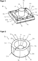
- FIG. 1 shows an embodiment of a first core part 10 of a transformer with continuous adjustment of the inductance.
- the first core part 10 has a center leg 11.
- the center leg 11 may be formed as a cylindrical rod core of the transformer.
- the first core part 10 comprises a support surface 130 with a slope.
- the bearing surface is designed on a Bearing surface of another core part of the Sprinttragerbauelements rest.
- the center leg 11 of the first core part 10 has an end face 111 on an end face 110.
- the bearing surface 130 of the first core part 10 is formed with respect to the end face 111 of the center leg 11 of the first core part 10 as an inclined plane with the mentioned slope.
- the pitch of the support surface 130 relative to the end face 111 may be, for example, between 0.1 ° and 5 °, preferably 2 °.
- the first core part 10 furthermore has a surface 12 from which a raised structure 13 protrudes.
- the bearing surface 130 of the first core part 10 is formed as a surface of the raised structure 13.
- the raised structure 13 may comprise at least a first projection 131 and a second projection 132.
- the first and second projections 131, 132 may protrude from the surface 12 of the first core member 10 on two opposite sides of the center leg 11.
- a first part of the bearing surface 130 of the first core part 10 is formed as a surface 1310 of the first projection 131.
- a second part of the bearing surface 130 of the first core part 10 is formed as a surface 1320 of the second projection 132.
- the surface 1310 of the first projection 131, which forms the first part of the bearing surface 130 of the first core part 10, and the surface 1320 of the second projection 132, which forms the second part of the bearing surface 130 of the first core part 10, are each in the form of a segment of a Shaped circular ring.
- the first core part 10 may further comprise a circular-shaped surface 14, from which the center leg 11 of the first Core part 10 protrudes have.
- the annular shaped surface 14 may be formed as a recess in the surface 12 of the first core member 10.
- the center leg 11 may be arranged in the center of the circular surface 14.
- the center leg 111 protrudes from the surface 14 further than the projections 131, 132 protrude from the surface 12.
- the projections 131, 132 thus have a lower height than the middle leg 111.
- FIG. 2 shows an embodiment of a second core portion 20 of the transformer component with continuous adjustment of the inductance.
- the second core part 20 includes a center leg 21.
- the second core part 20 has a support surface 230 with a slope.
- the support surface 230 is adapted to rest on the support surface 130 when the core member 20 is disposed on the core member 10.
- the center leg 21 of the second core part 20 has an end face 211 on an end face 210.
- the support surface 230 of the second core part 20 is formed opposite to the end face 211 of the center leg 21 as an inclined plane with the mentioned slope.
- the bearing surface 230 of the second core part 20 may, for example, have a pitch between 0.1 ° and 5 °, preferably 2 °, with respect to the end face 211.
- the second core part 20 may have a bottom part 22 and at least one side wall 23 which is arranged on a surface 220 of the bottom part.
- the middle leg 21 of the second core part 20 is arranged on the surface 220 of the bottom part 22 and is at least partially surrounded by the at least one side wall 23.
- the support surface 230 is on a side opposite the bottom part 22 side of the at least one side wall 23rd arranged.
- the bearing surface 230 may be formed as an arcuate or annular shaped surface of the at least one side wall 23.
- the support surface 230 may, for example, have at least two arcuately or semicircularly rising surfaces of the at least one side wall 23.
- the core part 20 is designed as a cap and thus as a hollow body open to one side.
- a cavity of the hollow body is bounded by the bottom part 22 and the at least one side wall 23.
- the center leg 21 protrudes from the bottom part 22.
- the middle leg 21 has a lower height than the at least one side wall 23.
- the bearing surface 230 of the second core part 20 has a first inclined plane 231, which is inclined with respect to a plane of the end face 211 of the center leg 21, and a second inclined plane 232, which also has a tilt relative to the end face 211 of the center leg 21 , on.
- the bearing surface 230 has a first shoulder 233 and a second shoulder 234.
- the first inclined plane 231 of the bearing surface 230 rises annularly from the first shoulder 233 to the second shoulder 234.
- the first inclined plane 231 of the support surface 230 may be formed as a first segment of a circular ring and rise from the first paragraph 233 to the second paragraph 234.
- the second inclined plane 232 rises annularly from the second paragraph 234 to the first paragraph 233.
- the second inclined plane 232 may be formed as a second segment of the annulus and rise from the second paragraph to the first paragraph.
- FIG. 3 shows a perspective view of the transformer component 1 after arranging the core part or the cap 20 on the core part 10.
- FIG. 4A shows a view of the transformer component 1 of FIG. 3 from a first page.
- FIG. 4B shows the transformer component 1 of FIG. 3 from a second page.
- the support surface 130 of the first core part 10 rests on the support surface 230 of the second core part 20.
- the end face 110 of the center leg 11 of the first core part 10 and the end face 210 of the center leg 21 of the second core part 20 are opposite.
- the end face 111 of the middle limb 11 of the first core part 10 and the end face 211 of the middle limb 21 of the second core part 20 face one another.
- a gap 30 with a certain width is formed between the end face 110 of the center leg 111 and the end face 210 of the center leg 21, a gap 30 with a certain width.
- the Figures 5A and 5B each show an inner cross-section of the transformer component 1 with the first core part 10 and the second core part 20, wherein the second core part 20 is arranged on the first core part 10, so that the end face 110 of the center leg 111 and the end face 210 of the center leg 21 face each other.
- a bobbin 50 is arranged on the center leg 11 of the first core part 10 and the middle leg 21 of the second core part 20, a bobbin 50 is arranged with a wire winding 60.
- the two core halves 10 and 20 can through one in the Figures 1 and 2 shown adhesive layer 40 which is applied to the support surface 130 of the first core member 10 and / or on the support surface 230 of the second core member 20, fixed to each other.
- the inductance or permeability of the transformer component 1 is in addition to the process parameters of the manufacturing process of the material parameters of the materials used, in particular the materials of the core halves 10, 20, the material of the wire used for the wire winding 60, the number of turns, and the geometric parameters, in particular the width the air gap between the end face 110 of the center leg 11 and the end face 210 of the center leg 21, depending. With the transformer component 1, the inductance or permeability of the component can be adjusted continuously at the end of the production process.
- the coil body 50 wound with the wire winding 60 is arranged on the first core part 10.
- the bobbin 50 may, for example, have a hollow tube 51, in which the middle leg 11 of the first core part 10 is arranged. After arranging the bobbin 50 with the wire winding 60 on the center leg 11, the wire winding is contacted at outer contact terminals of the core part 10.
- the adhesive coating 40 is applied to at least one of the bearing surfaces 130, 230 of the first and second core parts 10, 20.
- the second core part 20 is arranged on the first core part 10 such that the bearing surface 130 of the first core part 10 rests on the bearing surface 230 of the second core part 20.
- the end face 110 of the center leg 11 of the first core part 10 and the end face 210 of the center leg 21 of the second core part 20 opposite.
- the first and second core part 10, 20 are moved relative to each other such that the support surface 230 of the second core part 20 slides on the support surface 130 of the first core part 20. In this case, a position on which the support surface 230 of the second core part 20 rests on the support surface 130 of the first core part 10 shifts.
- an inductance of the transformer component 1 during movement of the first and second core members 10, 20 can be determined by connecting the external contact terminals of the transformer component to a suitable measuring device for measuring the inductance.
- the first and second core parts 10, 20 can be moved relative to one another during the measurement of the inductance of the transformer component until the inductance of the transformer component determined during the movement assumes a desired value.
- the bearing surface 230 of the second core part 20 rests on the bearing surface 130 of the first core part 10 in such a way that a gap width of the air gap 30 is almost 0 mm.
- the second core part 20 is opposite to the one in FIG. 5A shown position against the first core member 10 shifted so that the width of the air gap 30 between the end face 110 of the center leg 11 and the end face 210 of the center leg 21 has increased. This has in comparison to the position of the two core parts 10, 20 in FIG. 5A changed the inductance and the permeability of the inductive transformer component.
- the movement of the first and second core members 10, 20 relative to each other is stopped.
- the adhesive coating 40 which is applied to the support surface 130 of the first core member 10 and / or on the support surface 230 of the second core member 20 is cured in this position, so that the two core halves in this position, at which the inductance of the Studentstragerbauelements corresponds to the desired value , are fixed together.
- the first core part 10 is provided with the surface 12 from which the raised structure 13 protrudes, wherein the support surface 130 is formed as a surface of the raised structure 13 and wherein the raised structure 13 at least a first and a second projection 131, 132 projecting on two opposite sides of the center leg 11 of the first core member 10 from the surface 12 of the first core member 10 , having.
- a first part of the bearing surface 130 of the first core part 10 is formed as a surface 1310 of the first projection 131.
- a second part of the support surface 130 is formed as a surface 1320 of the second projection 132.
- the first core part 10 is provided during the manufacturing process such that the surface 1310 of the first projection 131 forming the first part of the bearing surface 130 of the first core part 10 and the surface 1320 of the second projection 132 forming the second part of the bearing surface 130 of the first core part 10 respectively are shaped in the form of a circular ring segment.
- the second core part 20 is provided with the bottom part 22 and the at least one side wall 23 arranged on the surface 220 of the bottom part 22.
- the middle leg 21 of the second core part 20 is arranged on the surface 220 of the bottom part 22 of the second core part 20 and is at least partially surrounded by the at least one side wall 23.
- the second core part 20 is provided such that the bearing surface 230 of the second core part 20 is arranged on a side of the at least one side wall 23 opposite the bottom part 22.
- the support surface 230 may have at least two arcuate or annular shaped rising surfaces of the at least one side wall 23.
- the width of the gap 30 between the end face 110 of the center leg 11 of the first core member 10 and the end face 210 of Central leg 21 of the second core part 20 is changed as a result of the rotational movement until the measured during the rotation inductance of the transformer component assumes the desired value. For example, if the measured inductance is too low, the two core parts 10, 20 are moved against each other such that the width of the gap 30 is reduced until the measured inductance value corresponds to the desired value.
- the first and second core parts 10, 20 are moved against each other such that the width of the air gap between the center leg 11 and the center leg 21 increases.
- the rotational movement is stopped and the first still liquid adhesive 40 between the support surface 130 and the support surface 230 cured.
- a desired inductance or permeability value of the transformer component can be set reliably in a simple manner without prior air gap grinding of the core halves 10, 20 and without the use of additional materials.
- the fluctuations in the inductance or permeability value which usually occur during the manufacture of a plurality of transformer components which are caused by fluctuations in the process parameters of the production process or by fluctuations in the material parameters of the core parts 10, 20, can be compensated, so that the manufactured Transmitter components having almost the same Induktellessutzrii permeability.
Landscapes
- Engineering & Computer Science (AREA)
- Power Engineering (AREA)
- Manufacturing & Machinery (AREA)
- Chemical & Material Sciences (AREA)
- Composite Materials (AREA)
- Microelectronics & Electronic Packaging (AREA)
- Coils Or Transformers For Communication (AREA)
- Transmission And Conversion Of Sensor Element Output (AREA)
Description
- Die Erfindung betrifft ein Übertragerbauelement mit Einstellung einer Induktivität des Übertragerbauelements während der Fertigung des Bauelements. Die Erfindung betrifft des Weiteren ein Verfahren zum Herstellen eines Übertragerbauelements mit Einstellung einer Induktivität des Übertragers während des Herstellprozesses.
- Zur Vermeidung einer Kernsättigung und zum Festlegen eines bestimmten Induktivitätswertes bei induktiven Bauelementen werden beispielsweise massive Eisen- oder Ferritkerne von Trafos und Drosseln mit einem Luftspalt versehen. Der Luftspalt stellt eine spaltförmige Unterbrechung des Magnetkerns dar und bestimmt die effektive Permeabilität µE des Magnetkreises sowie die Induktivität des fertig montierten induktiven Bauteils. Um die gewünschte Induktivität beziehungsweise Permeabilität zu erreichen, muss der Luftspalt eine vordefinierte Breite in möglichst engen Grenzen aufweisen.
- Ein Luftspalt kann nach dem Verpressen und Sintern nachträglich in den Kern eingeschliffen werden. Es zeigt sich jedoch, dass bei induktiven Bauelementen, bei denen der Luftspalt nach dem Verpressen und Sintern des Kerns in den Kern eingeschliffen wird, unterschiedliche Induktivitäts- beziehungsweise Permeabilitätswerte auftreten. Die unterschiedlichen Induktivitäts- und Permeabilitätswerte sind im Wesentlichen durch Schwankungen von Prozessparametern während des Herstellprozesses sowie durch geringfügig unterschiedliche Materialparameter des verwendeten Eisen- beziehungsweise Ferritmaterials des Kerns bedingt. Nachteilig ist insbesondere, dass das Einschleifen eines Spaltes in das Kernmaterial ein komplexer Vorgang ist, der mit erhöhten Kosten verbunden ist.
- Die Druckschrift
GB 751 037 A US 2005/104703 A1 betrifft einen Transformatorkern mit einem Spalt zwischen Mittelschenkeln zweier Kernteile, wobei ein Induktivitätswert des Transformators in Abhängigkeit von der Spaltbreite einstellbar ist. Die DruckschriftGB 1035378 A US 3,243,745 A betrifft ein anpassbares induktives Bauelement, bei dem eine Spaltbreite zwischen Mittelschenkeln zweier Kernteile variabel einstellbar ist, indem ein Zapfen aus magnetischem Material mittels einer Schraube unterschiedlich weit in den Spalt bewegt werden kann. - Das Anliegen der vorliegenden Erfindung ist es, ein Übertragerbauelement mit Einstellung einer Induktivität des Übertragerbauelements anzugeben, bei dem sich die Induktivität am Ende des Herstellprozesses auf einfache und zuverlässige Weise einstellen lässt. Eine weitere Aufgabe der vorliegenden Erfindung ist es, ein Verfahren zum Herstellen eines Übertragerbauelements mit Einstellung der Induktivität des Übertragerbauelements anzugeben, durch das es ermöglicht wird, die Induktivität des Übertragerbauelements am Ende des Herstellungsprozesses sicher und zuverlässig einzustellen.
- Ein Übertragerbauelement mit Einstellung der Induktivität wird im Patentanspruch 1 angegeben. Gemäß einer Ausführungs form umfasst das Übertragerbauelement ein erstes Kernteil mit einem Mittelschenkel und ein zweites Kernteil mit einem Mittelschenkel. Das erste Kernteil und das zweite Kernteil weisen jeweils eine Auflagefläche mit einer jeweiligen Steigung auf. Die Auflagefläche des ersten Kernteils liegt an der Auflagefläche des zweiten Kernteils auf. Eine Stirnseite des Mittelschenkel des ersten Kernteils und eine Stirnseite des Mittelschenkel des zweiten Kernteils stehen sich gegenüber. Eine Breite eines Spalts zwischen der Stirnseite des Mittelschenkels des ersten Kernteils und der Stirnseite des Mittelschenkels des zweiten Kernteils ist von einer Position, an der die Auflagefläche des ersten Kernteils an der Auflagefläche des zweiten Kernteils anliegt, abhängig.
- Eine Ausführungsform eines Verfahrens zum Herstellen eines Übertragerbauelements mit Einstellung der Induktivität ist im Patentanspruch 12 angegeben. Gemäß einer Ausführungsform umfasst das Verfahren zum Herstellen eines Übertragerbauelements mit Einstellung der Induktivität das Bereitstellen eines ersten Kernteils mit einem Mittelschenkel und eines zweiten Kernteils mit einem Mittelschenkel, wobei das erste Kernteil und das zweite Kernteil jeweils eine Auflagefläche aufweisen. Die jeweilige Auflagefläche des ersten und zweiten Kernteils weist eine Steigung auf. Das zweite Kernteil wird auf dem ersten Kernteil derart angeordnet, dass die Auflagefläche des ersten Kernteils an der Auflagefläche des zweiten Kernteils aufliegt und sich eine Stirnseite des Mittelschenkels des ersten Kernteils und eine Stirnseite des Mittelschenkels des zweiten Kernteils gegenüber stehen. Das erste und zweite Kernteil werden relativ zueinander derart bewegt, dass die Auflagefläche des zweiten Kernteils auf der Auflagefläche des ersten Kernteils gleitet und sich eine Position, an der die Auflagefläche des zweiten Kernteils auf der Auflagefläche des ersten Kernteils aufliegt, verschiebt und sich eine Breite eines Spalts zwischen der Stirnseite des Mittelschenkels des ersten Kernteils und der Stirnseite des Mittelschenkels des zweiten Kernteils verändert. Während des Bewegens des ersten und zweiten Kernteils relativ zueinander, wird eine Induktivität des Übertragerbauelements ermittelt. Das Bewegen des ersten und zweiten Kernteils relativ zueinander wird beendet, wenn die während des Bewegens ermittelte Induktivität einen Sollwert annimmt.
- Gemäß einer möglichen Ausführungsform des Übertragerbauelements können die beiden Kernteile, zwischen denen ein Luftspalt erzeugt werden soll, an den jeweiligen Auflageflächen der beiden Kernteile mit jeweils mindestens einer spiralförmigen oder bogenförmig geformten, schiefen Ebene versehen werden. Durch die schiefe Ebene der jeweiligen Auflagefläche der beiden Kernteile kann durch Verdrehen des ersten und zweiten Kernteils gegeneinander an einer dritten Berührfläche, insbesondere zwischen einer Stirnfläche der Stirnseite des Mittelschenkels des ersten Kernteils und einer Stirnfläche der Stirnseite des Mittelschenkels des zweiten Kernteils, ein Luftspalt mit veränderlicher Breite erzeugt werden, da durch die Verdrehung der beiden Kernteile eine Kernhälfte von der anderen Kernhälfte abgehoben wird.
- Somit kann bei dem angegebenen Übertragerbauelement beziehungsweise während des Herstellungsverfahrens der Luftspalt und damit die Permeabilität beziehungsweise Induktivität des Übertragers stufenlos eingestellt werden. Dadurch können mit identischen Rohkernen beliebige Induktivitätswerte bei der Endmontage des Übertragerbauelements hergestellt werden. Eine Lagerhaltung von verschiedenen vordefinierten Kernrohlingen ist nicht notwendig.
- Grundsätzlich ist die Induktivität beziehungsweise Permeabilität eines Übertragerbauelements von Schwankungen der Prozessparameter während des Herstellprozesses, beispielsweise von der Art des Sinterns, von den Materialparametern der für den Kern verwendeten Materialien sowie von geometrischen Parametern, beispielsweise der Form des Kerns, abhängig. Zu den geometrischen Parametern gehört auch die Breite des Luftspalts zwischen den beiden Kernhälften. Die Breite des Luftspalts hat wesentlichen Einfluss auf die Permeabilität beziehungsweise Induktivität des fertigen Bauelements. Da die Breite des Luftspalts bei der Endmontage des magnetischen Bauteils durch die Kerne selbst eingestellt werden kann, können Dimensions- und Prozessschwankungen sowie Schwankungen der Materialparameter der verwendeten Materialien sowie eines Drahtwickels des Übertragers bis hin zu Schwankungen der Windungszahlen der Drähte der Drahtwicklung des Übertragers ausgeglichen werden.
- Der sogenannte Luftspalt muss nicht zwangsläufig Luft enthalten. Der Begriff "Luftspalt" bezeichnet, wie eingangs erläutert, jegliche Kernunterbrechung, durch die der magnetische Fluss unterbrochen wird. Im Unterschied zu Verfahren zur Erzeugung eines Luftspalts in einem magnetischen Kreis, bei dem der Luftspalt eingestellt wird, indem zusätzliches nicht magnetisches Material, wie zum Beispiel Papier oder Plastik, als Abstandshalter mit der Solldicke des Luftspalts in den Spalt zwischen den Kernschenkeln eingelegt wird, ist es bei dem angegebenen Übertragerbauelement beziehungsweise dem Herstellungsverfahren nicht notwendig, zusätzliche Materialien, die möglicherweise mit Toleranzen in der Dicke der Materialien behaftet sind, zu verwenden, so dass der Herstellaufwand und die dafür aufzuwendenden Kosten gering ausfallen.
- Im Unterschied zu einem Verfahren, bei dem der Luftspalt eingestellt wird, indem mindestens einer der Schenkel, beispielsweise bei E-Kernen der mittlere Schenkel, meist durch ein aufwändiges und separates Schleifen der Schenkelhälften gekürzt wird, entfällt bei dem erfindungsgemäßen Verfahren das kostenintensive Schleifen der Kerne. Die Kerne müssen nicht bereits vor der Endmontage des Bauteils durch Herunterschleifen von Material auf einem Schenkel bearbeitet werden.
- Im Vergleich zu Übertragerbauelementen und den zugehörigen Herstellungsverfahren, bei denen zur genauen Justage der Induktivität, insbesondere zur nachträglichen Einstellung des Luftspalts, zusätzlich eine magnetisch leitfähige Abgleichschraube als teilweise Überbrückung des Luftspalts in den Spalt zwischen die Mittelschenkel zweier Kernhälften eingeschraubt wird, ist bei dem erfindungsgemäßen Übertragerbauelement beziehungsweise dem Herstellungsverfahren die Verwendung zusätzlicher Materialien, beispielsweise die Verwendung von Abstandshaltern oder einer Abgleichschraube, im Luftspalt nicht erforderlich. Somit wird das Übertragerbauelement durch die zusätzlichen Materialien nicht unnötig vergrößert und der Montageaufwand sowie die mit der Montage verbundenen Kosten sind gering.
- Darüber hinaus ist das Übertragerbauelement nicht von einer Reduzierung der Kernsättigung betroffen, die bei Verwendung einer Abgleichschraube durch das dafür notwendige Mittelloch im Mittelschenkel auftritt. Gegenüber einer UV-Kleber-Methode, bei der ein Kleber mit UV-Aushärtung nach definierter Messung der Induktivität aushärtet, kann mit dem angegebenen Übertragerbauelement beziehungsweise dem Herstellungsverfahren eine größere Breite des Luftspalts realisiert werden. Eventuell kann die Verwendung eines UV-Klebers zwischen den Auflageflächen des ersten und zweiten Kernteils gegenüber einer UV-Kleber-Methode vollständig entfallen und nur eine Standard-Kern-Kernklebung erforderlich sein, wenn sich die Stellung der beiden Kernteile bis zur Aushärtung des Klebers nicht verändern kann.
- Die Erfindung wird im Folgenden anhand von Figuren, die Ausführungsbeispiele der vorliegenden Erfindung zeigen, näher erläutert. Es zeigen:
- Figur 1
- eine Ausführungsform eines ersten Kernteils eines Übertragerbauelements mit stufenloser Einstellung der Induktivität,
- Figur 2
- eine Ausführungsform eines zweiten Kernteils eines Übertragerbauelements mit stufenloser Einstellung der Induktivität,
- Figur 3
- eine perspektivische Ansicht einer Ausführungsform eines Übertragerbauelements mit stufenloser Einstellung der Induktivität,
- Figur 4A
- eine Ansicht einer Ausführungsform eines Übertragerbauelements mit stufenloser Einstellung der Induktivität von einer Seite,
- Figur 4B
- eine Ansicht einer Ausführungsform eines Übertragerbauelements mit stufenloser Einstellung der Induktivität von einer anderen Seite,
- Figur 5A
- einen inneren Querschnitt einer Ausführungsform eines Übertragerbauelements mit stufenloser Einstellung der Induktivität mit einer ersten eingestellten Spaltbreite,
- Figur 5B
- einen inneren Querschnitt einer Ausführungsform eines Übertragerbauelements mit stufenloser Einstellung der Induktivität mit einer zweiten eingestellten Spaltbreite.
-
Figur 1 zeigt eine Ausführungsform eines ersten Kernteils 10 eines Übertragerbauelements mit stufenloser Einstellung der Induktivität. Das erste Kernteil 10 weist einen Mittelschenkel 11 auf. Der Mittelschenkel 11 kann als ein zylinderförmiger Stabkern des Übertragers ausgebildet sein. Des Weiteren umfasst das erste Kernteil 10 eine Auflagefläche 130 mit einer Steigung. Die Auflagefläche ist dazu ausgebildet, auf einer Auflagefläche eines weiteren Kernteils des Übertragerbauelements aufzuliegen. Der Mittelschenkel 11 des ersten Kernteils 10 weist an einer Stirnseite 110 eine Stirnfläche 111 auf. Die Auflagefläche 130 des ersten Kernteils 10 ist gegenüber der Stirnfläche 111 des Mittelschenkels 11 des ersten Kernteils 10 als eine schiefe Ebene mit der erwähnten Steigung ausgebildet. Die Steigung der Auflagefläche 130 gegenüber der Stirnfläche 111 kann beispielsweise zwischen 0,1° und 5°, vorzugsweise 2°, betragen. - Das erste Kernteil 10 weist des Weiteren eine Fläche 12, aus der eine erhabene Struktur 13 herausragt, auf. Die Auflagefläche 130 des ersten Kernteils 10 ist als eine Oberfläche der erhabenen Struktur 13 ausgebildet. Gemäß einer möglichen Ausführungsform kann die erhabene Struktur 13 mindestens einen ersten Vorsprung 131 und einen zweiten Vorsprung 132 aufweisen. Der erste und zweite Vorsprung 131, 132 können auf zwei gegenüberliegenden Seiten des Mittelschenkels 11 aus der Fläche 12 des ersten Kernteils 10 hervorragen.
- Ein erster Teil der Auflagefläche 130 des ersten Kernteils 10 ist als eine Oberfläche 1310 des ersten Vorsprungs 131 ausgebildet. Ein zweiter Teil der Auflagefläche 130 des ersten Kernteils 10 ist als eine Oberfläche 1320 des zweiten Vorsprungs 132 ausgebildet. Die Oberfläche 1310 des ersten Vorsprungs 131, die den ersten Teil der Auflagefläche 130 des ersten Kernteils 10 bildet, und die Oberfläche 1320 des zweiten Vorsprungs 132, die den zweiten Teil der Auflagefläche 130 des ersten Kernteils 10 bildet, sind jeweils in Form eines Segments eines Kreisrings geformt.
- Das erste Kernteil 10 kann des Weiteren eine kreisringförmig geformte Fläche 14, aus der der Mittelschenkel 11 des ersten Kernteils 10 hervorragt, aufweisen. Die kreisringförmig geformte Fläche 14 kann beispielsweise als eine Vertiefung in der Fläche 12 des ersten Kernteils 10 ausgebildet sein. Der Mittelschenkel 11 kann im Zentrum der kreisförmigen Fläche 14 angeordnet sein. Der Mittelschenkel 111 ragt aus der Fläche 14 weiter hervor als die Vorsprünge 131, 132 aus der Fläche 12 hervorragen. Die Vorsprünge 131, 132 haben somit eine geringere Höhe als der Mittelschenkel 111.
-
Figur 2 zeigt eine Ausführungsform eines zweiten Kernteils 20 des Übertragerbauelements mit stufenloser Einstellung der Induktivität. Das zweite Kernteil 20 umfasst einen Mittelschenkel 21. Darüber hinaus weist das zweite Kernteil 20 eine Auflagefläche 230 mit einer Steigung auf. Die Auflagefläche 230 ist dazu ausgebildet, auf der Auflagefläche 130 aufzuliegen, wenn das Kernteil 20 auf dem Kernteil 10 angeordnet wird. Der Mittelschenkel 21 des zweiten Kernteils 20 weist an einer Stirnseite 210 eine Stirnfläche 211 auf. Die Auflagefläche 230 des zweiten Kernteils 20 ist gegenüber der Stirnfläche 211 des Mittelschenkels 21 als eine schiefe Ebene mit der erwähnten Steigung ausgebildet. Die Auflagefläche 230 des zweiten Kernteils 20 kann gegenüber der Stirnfläche 211 beispielsweise eine Steigung zwischen 0,1° und 5°, vorzugsweise 2°, haben. - Gemäß einer möglichen Ausführungsform kann das zweite Kernteil 20 ein Bodenteil 22 und mindestens eine Seitenwand 23, die auf einer Fläche 220 des Bodenteils angeordnet ist, aufweisen. Der Mittelschenkel 21 des zweiten Kernteils 20 ist auf der Fläche 220 des Bodenteils 22 angeordnet und ist zumindest teilweise von der mindestens einen Seitenwand 23 umgeben. Die Auflagefläche 230 ist an einer dem Bodenteil 22 gegenüberliegenden Seite der mindestens einen Seitenwand 23 angeordnet. Die Auflagefläche 230 kann als eine bogenförmig oder kreisringförmig geformte Oberfläche der mindestens einen Seitenwand 23 ausgebildet sein. Die Auflagefläche 230 kann beispielsweise mindestens zwei bogenförmig oder halbkreisförmig ansteigend geformte Oberflächen der mindestens einen Seitenwand 23 aufweisen.
- Bei der in
Figur 2 gezeigten Ausführungsform ist das Kernteil 20 als eine Kappe und somit als ein nach einer Seite offener Hohlkörper ausgebildet. Ein Hohlraum des Hohlkörpers ist von dem Bodenteil 22 und der mindestens einen Seitenwand 23 begrenzt. Im Inneren des Hohlraums ragt der Mittelschenkel 21 von dem Bodenteil 22 empor. Der Mittelschenkel 21 hat eine geringere Höhe als die mindestens eine Seitenwand 23. - Gemäß einer möglichen Ausführungsform weist die Auflagefläche 230 des zweiten Kernteils 20 eine erste schiefe Ebene 231, die gegenüber einer Ebene der Stirnfläche 211 des Mittelschenkels 21 geneigt ist, und eine zweite schiefe Ebene 232, die ebenfalls gegenüber der Stirnfläche 211 des Mittelschenkels 21 eine Neigung hat, auf. Die Auflagefläche 230 weist einen ersten Absatz 233 und einen zweiten Absatz 234 auf. Die erste schiefe Ebene 231 der Auflagefläche 230 steigt kreisringförmig von dem ersten Absatz 233 zu dem zweiten Absatz 234 an. Die erste schiefe Ebene 231 der Auflagefläche 230 kann als ein erstes Segment eines Kreisrings geformt sein und von dem ersten Absatz 233 zu dem zweiten Absatz 234 ansteigen. Die zweite schiefe Ebene 232 steigt kreisringförmig von dem zweiten Absatz 234 zu dem ersten Absatz 233 an. Die zweite schiefe Ebene 232 kann als ein zweites Segment des Kreisrings geformt sein und von dem zweiten Absatz zu dem ersten Absatz ansteigen.
- Zur Montage des Übertragerbauelements wird das als Kappe geformte zweite Kernteil 20 auf das Kernteil 10 aufgesetzt. Figur 3 zeigt in perspektivischer Ansicht das Übertragerbauelement 1 nach dem Anordnen des Kernteils beziehungsweise der Kappe 20 auf dem Kernteil 10.
Figur 4A zeigt eine Ansicht des Übertragerbauelements 1 derFigur 3 von einer ersten Seite.Figur 4B zeigt das Übertragerbauelement 1 derFigur 3 von einer zweiten Seite. - Nach dem Zusammensetzen des ersten und zweiten Kernteils 10, 20 liegt die Auflagefläche 130 des ersten Kernteils 10 auf der Auflagefläche 230 des zweiten Kernteils 20 auf. Dabei stehen sich die Stirnseite 110 des Mittelschenkels 11 des ersten Kernteils 10 und die Stirnseite 210 des Mittelschenkels 21 des zweiten Kernteils 20 gegenüber. Insbesondere stehen sich die Stirnfläche 111 des Mittelschenkels 11 des ersten Kernteils 10 und die Stirnfläche 211 des Mittelschenkels 21 des zweiten Kernteils 20 gegenüber. In Abhängigkeit von einer Position, an der die Auflagefläche 130 des ersten Kernteils 10 an der Auflagefläche 230 des zweiten Kernteils 20 anliegt, entsteht zwischen der Stirnseite 110 des Mittelschenkels 111 und der Stirnseite 210 des Mittelschenkels 21 ein Spalt 30 mit einer bestimmten Breite.
- Die
Figuren 5A und5B zeigen jeweils einen inneren Querschnitt des Übertragerbauelements 1 mit dem ersten Kernteil 10 und dem zweiten Kernteil 20, wobei das zweite Kernteil 20 auf dem ersten Kernteil 10 angeordnet ist, sodass sich die Stirnseite 110 des Mittelschenkels 111 und die Stirnseite 210 des Mittelschenkels 21 gegenüberstehen. Auf dem Mittelschenkel 11 des ersten Kernteils 10 und dem Mittelschenkel 21 des zweiten Kernteils 20 ist ein Spulenkörper 50 mit einer Drahtwicklung 60 angeordnet. Die beiden Kernhälften 10 und 20 können durch eine in denFiguren 1 und 2 gezeigte Klebstoffschicht 40, die auf der Auflagefläche 130 des ersten Kernteils 10 und/oder auf der Auflagefläche 230 des zweiten Kernteils 20 aufgebracht ist, aneinander fixiert sein. - Die Induktivität beziehungsweise Permeabilität des Übertragerbauelements 1 ist neben den Prozessparametern des Herstellprozesses von den Materialparametern der verwendeten Materialien, insbesondere der Materialien der Kernhälften 10, 20, dem Material des für die Drahtwicklung 60 verwendeten Drahtes, der Windungszahlen, und der geometrischen Parameter, insbesondere der Breite des Luftspalts zwischen der Stirnseite 110 des Mittelschenkels 11 und der Stirnseite 210 des Mittelschenkels 21, abhängig. Mit dem Übertragerbauelement 1 lässt sich die Induktivität beziehungsweise Permeabilität des Bauelements am Ende des Herstellungsprozesses stufenlos einstellen.
- Dazu wird beispielsweise zunächst der mit der Drahtwicklung 60 bewickelte Spulenkörper 50 auf dem ersten Kernteil 10 angeordnet. Der Spulenkörper 50 kann beispielsweise ein Hohlrohr 51 aufweisen, in dem der Mittelschenkel 11 des ersten Kernteils 10 angeordnet wird. Nach dem Anordnen des Spulenkörpers 50 mit der Drahtwicklung 60 auf dem Mittelschenkel 11 wird die Drahtwicklung an äußeren Kontaktanschlüssen des Kernteils 10 kontaktiert.
- Die Klebstoffbeschichtung 40 wird auf mindestens eine der Auflageflächen 130, 230 des ersten und zweiten Kernteils 10, 20 aufgebracht. Nachfolgend wird das zweite Kernteil 20 auf dem ersten Kernteil 10 derart angeordnet, so dass die Auflagefläche 130 des ersten Kernteils 10 auf der Auflagefläche 230 des zweiten Kernteils 20 aufliegt. Des Weiteren stehen sich nach dem Anordnen des zweiten Kernteils 20 auf dem ersten Kernteil 10 die Stirnseite 110 des Mittelschenkels 11 des ersten Kernteils 10 und die Stirnseite 210 des Mittelschenkels 21 des zweiten Kernteils 20 gegenüber. Dabei ist eine Breite des Spalts 30 zwischen der Stirnseite 110 des Mittelschenkels 11 des ersten Kernteils 10 und der Stirnseite 210 des Mittelschenkels 21 des zweiten Kernteils 20 von einer Position, an der die Auflagefläche 130 des ersten Kernteils 10 an der Auflagefläche 230 des zweiten Kernteils 20 anliegt, abhängig.
- Nach dem Aufsetzen des zweiten Kernteils 20 auf dem ersten Kernteil 10 werden das erste und zweite Kernteil 10, 20 relativ zueinander derart bewegt, dass die Auflagefläche 230 des zweiten Kernteils 20 auf der Auflagefläche 130 des ersten Kernteils 20 gleitet. Dabei verschiebt sich eine Position, an der die Auflagefläche 230 des zweiten Kernteils 20 auf der Auflagefläche 130 des ersten Kernteils 10 aufliegt. Da die Auflagefläche 130 des ersten Kernteils 10 gegenüber der Stirnfläche 111 des Mittelschenkels 11 und die Auflagefläche 230 des zweiten Kernteils 20 gegenüber der Stirnfläche 211 des Mittelschenkels 21 des zweiten Kernteils 20 eine Schräge aufweist, verändert sich durch das Bewegen des ersten und zweiten Kernteils 10, 20 gegeneinander die Breite des Spalts 30 zwischen der Stirnseite 110 des Mittelschenkels 11 und der Stirnseite 210 des Mittelschenkels 21.
- Da die Drahtwicklung 60 an Kontaktanschlüssen des Kernteils 10 kontaktiert ist, lässt sich eine Induktivität des Übertragerbauelements 1 während des Bewegens des ersten und zweiten Kernteils 10, 20 ermitteln, indem die externen Kontaktanschlüsse des Übertragerbauelements an ein geeignetes Messgerät zum Messen der Induktivität angeschlossen werden. Das erste und zweite Kernteil 10, 20 können während des Messens der Induktivität des Übertragerbauelements gegeneinander solange bewegt werden, bis die während des Bewegens ermittelte Induktivität des Übertragerbauelements einen Sollwert annimmt.
- Bei der in
Figur 5A gezeigten Ausführungsform liegt die Auflagefläche 230 des zweiten Kernteils 20 auf der Auflagefläche 130 des ersten Kernteils 10 derart auf, dass eine Spaltbreite des Luftspalts 30 nahezu 0 mm beträgt. Bei der inFigur 5B gezeigten Ausführungsform ist das zweite Kernteil 20 gegenüber der inFigur 5A gezeigten Position derart gegen das erste Kernteil 10 verschoben, dass sich die Breite des Luftspalts 30 zwischen der Stirnseite 110 des Mittelschenkels 11 und der Stirnseite 210 des Mittelschenkels 21 vergrößert hat. Dadurch hat sich im Vergleich zur Stellung der beiden Kernteile 10, 20 inFigur 5A die Induktivität und die Permeabilität des induktiven Übertragerbauelements verändert. - Wenn die gemessene Induktivität beim Bewegen des zweiten Kernteils 20 auf dem ersten Kernteil 10 den gewünschten Sollwert annimmt, wird das Bewegen des ersten und zweiten Kernteils 10, 20 relativ zueinander beendet. Die Klebstoffbeschichtung 40, die auf die Auflagefläche 130 des ersten Kernteils 10 und/oder auf die Auflagefläche 230 des zweiten Kernteils 20 aufgebracht ist, wird in dieser Position ausgehärtet, sodass die beiden Kernhälften in dieser Stellung, an der die Induktivität des Übertragerbauelements dem Sollwert entspricht, miteinander fixiert sind.
- Gemäß einer möglichen Ausführungsform des Herstellungsverfahrens wird das erste Kernteil 10 mit der Fläche 12, aus der die erhabene Struktur 13 herausragt, bereitgestellt, wobei die Auflagefläche 130 als eine Oberfläche der erhabenen Struktur 13 ausgebildet ist und wobei die erhabene Struktur 13 mindestens einen ersten und einen zweiten Vorsprung 131, 132, die auf zwei gegenüberliegenden Seiten des Mittelschenkels 11 des ersten Kernteils 10 aus der Fläche 12 des ersten Kernteils 10 hervorragen, aufweist. Ein erster Teil der Auflagefläche 130 des ersten Kernteils 10 ist als eine Oberfläche 1310 des ersten Vorsprungs 131 ausgebildet. Ein zweiter Teil der Auflagefläche 130 ist als eine Oberfläche 1320 des zweiten Vorsprungs 132 ausgebildet. Das erste Kernteil 10 wird während des Herstellungsverfahrens derart bereitgestellt, dass die den ersten Teil der Auflagefläche 130 des ersten Kernteils 10 bildende Oberfläche 1310 des ersten Vorsprungs 131 und die den zweiten Teil der Auflagefläche 130 des ersten Kernteils 10 bildende Oberfläche 1320 des zweiten Vorsprungs 132 jeweils in Form eines Kreisringsegments geformt sind.
- Das zweite Kernteil 20 wird mit dem Bodenteil 22 und der mindestens einen Seitenwand 23, die auf der Fläche 220 des Bodenteils 22 angeordnet ist, bereitgestellt. Der Mittelschenkel 21 des zweiten Kernteils 20 ist auf der Fläche 220 des Bodenteils 22 des zweiten Kernteils 20 angeordnet und ist zumindest teilweise von der mindestens einen Seitenwand 23 umgeben. Des Weiteren wird das zweite Kernteil 20 derart bereitgestellt, dass die Auflagefläche 230 des zweiten Kernteils 20 an einer dem Bodenteil 22 gegenüberliegenden Seite der mindestens einen Seitenwand 23 angeordnet ist. Die Auflagefläche 230 kann mindestens zwei bogenförmig oder kreisringförmig geformte ansteigende Oberflächen der mindestens einen Seitenwand 23 aufweisen.
- Bei dieser Ausführungsform erfolgt das Bewegen des ersten und zweiten Kernteils 10, 20 relativ zueinander durch ein gegeneinander Verdrehen des ersten und zweiten Kernteils 10, 20. Die Breite des Spalts 30 zwischen der Stirnseite 110 des Mittelschenkels 11 des ersten Kernteils 10 und der Stirnseite 210 des Mittelschenkels 21 des zweiten Kernteils 20 wird infolge der Drehbewegung solange verändert, bis die während des Drehens gemessene Induktivität des Übertragerbauelements den gewünschten Sollwert annimmt. Wenn die gemessene Induktivität beispielsweise zu niedrig ist, werden die beiden Kernteile 10, 20 derart gegeneinander bewegt, dass die Breite des Spalts 30 verkleinert wird, bis der gemessene Induktivitätswert dem Sollwert entspricht. Wenn umgekehrt die gemessene Induktivität gegenüber dem Sollwert der Induktivität zu hoch ist, werden das erste und zweite Kernteil 10, 20 gegeneinander derart bewegt, dass sich die Breite des Luftspalts zwischen dem Mittelschenkel 11 und dem Mittelschenkel 21 vergrößert. Wenn der Sollwert erreicht wird, wird die Drehbewegung beendet und der zunächst noch flüssige Kleber 40 zwischen der Auflagefläche 130 und der Auflagefläche 230 ausgehärtet.
- Mit dem angegebenen Übertragerbauelement 1 beziehungsweise dem angegebenen Herstellungsverfahren lässt sich ohne vorheriges Luftspaltschleifen der Kernhälften 10, 20 und ohne die Verwendung von zusätzlichen Materialien ein angestrebter Induktivitäts- beziehungsweise Permeabilitätswert des Übertragerbauelements auf einfache Weise zuverlässig einstellen. Dadurch können die beim Fertigen einer Vielzahl von Übertragerbauelementen üblicherweise auftretenden Schwankungen des Induktivitäts- beziehungsweise Permeabilitätswerts, die durch Schwankungen der Prozessparameter des Herstellprozesses oder durch Schwankungen der Materialparameter der Kernteile 10, 20 bedingt sind, ausgeglichen werden, sodass die hergestellten Übertragerbauelemente mit nahezu den gleichen Induktivitätsbeziehungsweise Permeabilitätswert aufweisen.
-
- 1
- Übertragerbauelement
- 10
- erstes Kernteil
- 11
- Mittelschenkel
- 12
- Fläche des ersten Kernteils
- 13
- erhabene Struktur
- 20
- zweites Kernteil
- 21
- Mittelschenkel des zweiten Kernteils
- 22
- Bodenteil
- 23
- Seitenwand
- 30
- Spalt
- 40
- Klebstoffbeschichtung
- 50
- Spulenkörper
- 60
- Drahtwicklung
- 110
- Stirnseite des Mittelschenkels
- 130
- Auflagefläche des ersten Kernteils
- 210
- Stirnseite des Mittelschenkels
- 230
- Auflagefläche des zweiten Kernteils
Claims (15)
- Übertragerbauelement mit Einstellung einer Induktivität, umfassend:- ein erstes Kernteil (10) mit einem Mittelschenkel (11),- ein zweites Kernteil (20) mit einem Mittelschenkel (21),- wobei das erste Kernteil (10) und das zweite Kernteil (20) jeweils eine Auflagefläche (130, 230) mit einer jeweiligen Steigung aufweisen,- wobei die Auflagefläche (130) des ersten Kernteils (10) an der Auflagefläche (230) des zweiten Kernteils (20) aufliegt,- wobei sich eine Stirnseite (110) des Mittelschenkel (11) des ersten Kernteils (10) und eine Stirnseite (210) des Mittelschenkel (21) des zweiten Kernteils (20) gegenüber stehen,- wobei eine Breite eines Spalts (30) zwischen der Stirnseite (110) des Mittelschenkels (11) des ersten Kernteils (10) und der Stirnseite (210) des Mittelschenkels (21) des zweiten Kernteils (20) von einer Position, an der die Auflagefläche (130) des ersten Kernteils (10) an der Auflagefläche (230) des zweiten Kernteils (20) anliegt, abhängig ist.
- Übertragerbauelement nach Anspruch 1,
wobei die jeweilige Steigung der Auflagefläche (130, 230) des ersten und zweiten Kernteils (10, 20) jeweils zwischen 0,1° und 5° beträgt. - Übertragerbauelement nach einem der Ansprüche 1 oder 2,- wobei der Mittelschenkel (11) des ersten Kernteils (10) und der Mittelschenkel (21) des zweiten Kernteils (20) an ihrer jeweiligen Stirnseite (110, 210) jeweils eine Stirnfläche (111, 211) aufweisen,- wobei sich die Stirnfläche (111) des Mittelschenkels (11) des ersten Kernteils (10) und die Stirnfläche (211) des Mittelschenkels (21) des zweiten Kernteils (20) gegenüber stehen,- wobei die Auflagefläche (130) des ersten Kernteils (10) gegenüber der Stirnfläche (111) des Mittelschenkels (11) des ersten Kernteils (10) als eine schiefe Ebene mit der Steigung ausgebildet ist,- wobei die Auflagefläche (230) des zweiten Kernteils (20) gegenüber der Stirnfläche (211) des Mittelschenkels (21) des zweiten Kernteils (20) als eine schiefe Ebene mit der Steigung ausgebildet ist.
- Übertragerbauelement nach einem der Ansprüche 1 bis 3,- wobei das erste Kernteil (10) eine Fläche (12), aus der eine erhabene Struktur (13) herausragt, aufweist,- wobei die Auflagefläche (130) des ersten Kernteils (10) als eine Oberfläche der erhabenen Struktur (13) ausgebildet ist.
- Übertragerbauelement nach Anspruch 4,- wobei die erhabene Struktur (13) mindestens einen ersten und einen zweiten Vorsprung (131, 132), die aus der Fläche (12) des ersten Kernteils (10) hervorragen, aufweist,- wobei ein erster Teil der Auflagefläche (130) des ersten Kernteils (10) als eine Oberfläche (1310) des ersten Vorsprungs (131) und ein zweiter Teil der Auflagefläche (130) des ersten Kernteils (10) als eine Oberfläche (1320) des zweiten Vorsprungs (132) ausgebildet ist,- wobei die den ersten Teil der Auflagefläche (130) des ersten Kernteils (10) bildende Oberfläche (1310) des ersten Vorsprungs (131) und die den zweiten Teil der Auflagefläche (130) des ersten Kernteils (10) bildende Oberfläche (1320) des zweiten Vorsprungs (132) jeweils in Form eines Kreisringsegments geformt sind.
- Übertragerbauelement nach einem der Ansprüche 4 oder 5,- wobei das erste Kernteil (10) eine kreisringförmig geformte Fläche (14), aus der der Mittelschenkel (11) des ersten Kernteils (10) hervorragt, aufweist,- wobei die kreisringförmig geformte Fläche (14) als eine Vertiefung in der Fläche (12) des ersten Kernteils (10) ausgebildet ist.
- Übertragerbauelement nach einem der Ansprüche 1 bis 6,- wobei das zweite Kernteil (20) ein Bodenteil (22) und mindestens eine Seitenwand (23), die auf einer Fläche (220) des Bodenteils angeordnet ist, aufweist,- wobei der Mittelschenkel (21) des zweiten Kernteils (20) auf der Fläche (220) des Bodenteils (22) des zweiten Kernteils (20) angeordnet ist und zumindest teilweise von der Seitenwand (23) umgeben ist,- wobei die Auflagefläche (230) des zweiten Kernteils (20) an einer dem Bodenteil (22) gegenüberliegenden Seite der mindestens einen Seitenwand (23) angeordnet ist,- wobei die Auflagefläche (230) mindestens zwei Oberflächen der mindestens einen Seitenwand (23), die jeweils als Segmente eines Kreisrings geformt sind, aufweist.
- Übertragerbauelement nach Anspruch 7,
wobei das zweite Kernteil (20) als ein nach einer Seite offener Hohlkörper mit einem Hohlraum, der von dem Bodenteil (22) und der mindestens einen Seitenwand (23) begrenzt ist, ausgebildet ist. - Übertragerbauelement nach einem der Ansprüche 1 bis 8,- wobei die Auflagefläche (230) des zweiten Kernteils (20) eine erste und zweite in Bezug auf eine Ebene der Stirnfläche (211) des Mittelschenkels (21) des zweiten Kernteils (20) schiefe Ebene (231, 232) aufweist,- wobei die Auflagefläche (230) des zweiten Kernteils (20) einen ersten und zweiten Absatz (233, 234) aufweist,- wobei die erste schiefe Ebene (231) der Auflagefläche (230) des zweiten Kernteils (20) als ein erstes Segment eines Kreisrings geformt ist und von dem ersten Absatz (233) zu dem zweiten Absatz (234) ansteigt,- wobei die zweite schiefe Ebene (232) der Auflagefläche (230) des zweiten Kernteils (20) als ein zweites Segment des Kreisrings geformt ist und von dem zweiten Absatz (234) zu dem ersten Absatz (233) ansteigt.
- Übertragerbauelement nach einem der Ansprüche 1 bis 9, wobei zwischen der Auflagefläche (130) des ersten Kernteils (10) und der Auflagefläche (230) des zweiten Kernteils (20) eine Klebstoffschicht (40) angeordnet ist.
- Übertragerbauelement nach einem der Ansprüche 1 bis 10, umfassend:- einen Spulenkörper (50) mit einer Drahtwicklung (60),- wobei der Spulenkörper (50) auf dem Mittelschenkel (11) des ersten Kernteils (10) und dem Mittelschenkel (21) des zweiten Kernteils (20) angeordnet ist.
- Verfahren zum Herstellen eines Übertragerbauelements mit Einstellung einer Induktivität, umfassend:- Bereitstellen eines ersten Kernteils (10) des Übertragerbauelements (1) mit einem Mittelschenkel (11) und eines zweiten Kernteils (20) des Übertragerbauelements (1) mit einem Mittelschenkel (21), wobei das erste Kernteil (10) und das zweite Kernteil (20) jeweils eine Auflagefläche (130, 230) aufweisen, wobei die jeweilige Auflagefläche (130, 230) des ersten und zweiten Kernteils (10, 20) eine Steigung aufweist,- Anordnen des zweiten Kernteils (20) auf dem ersten Kernteil (10) derart, dass die Auflagefläche (130) des ersten Kernteils (10) an der Auflagefläche (230) des zweiten Kernteils (20) aufliegt und sich eine Stirnseite (110) des Mittelschenkels (11) des ersten Kernteils (10) und eine Stirnseite (210) des Mittelschenkels (21) des zweiten Kernteils (20) gegenüber stehen,- Bewegen des ersten und zweiten Kernteils (20) relativ zueinander derart, dass die Auflagefläche (230) des zweiten Kernteils (20) auf der Auflagefläche (130) des ersten Kernteils (10) gleitet und sich eine Position, an der die Auflagefläche (230) des zweiten Kernteils (20) auf der Auflagefläche (130) des ersten Kernteils (10) aufliegt, verschiebt und sich eine Breite eines Spalts (30) zwischen der Stirnseite (110) des Mittelschenkels (11) des ersten Kernteils (10) und der Stirnseite (210) des Mittelschenkels (21) des zweiten Kernteils (20) verändert,- Ermitteln einer Induktivität des Übertragerbauelements (1) während des Bewegens des ersten und zweiten Kernteils (10, 20) relativ zueinander,- Beenden des Bewegens des ersten und zweiten Kernteils (10, 20) relativ zueinander, wenn die während des Bewegens ermittelte Induktivität einen Sollwert annimmt.
- Verfahren nach Anspruch 12,- Bereitstellen des ersten Kernteils (10) mit einer Fläche (12), aus der eine erhabene Struktur (13) herausragt, wobei die Auflagefläche (130) als eine Oberfläche der erhabenen Struktur (13) ausgebildet ist, wobei die erhabene Struktur (13) mindestens einen ersten und einen zweiten Vorsprung (131, 132), die aus der Fläche (12) des ersten Kernteils (10) hervorragen, aufweist, wobei ein erster Teil der Auflagefläche (130) des ersten Kernteils (10) als eine Oberfläche (1310) des ersten Vorsprungs (131) und ein zweiter Teil der Auflagefläche (130) des ersten Kernteils (10) als eine Oberfläche (1320) des zweiten Vorsprungs (132) ausgebildet ist, wobei die den ersten Teil der Auflagefläche (130) des ersten Kernteils (10) bildende Oberfläche (1310) des ersten Vorsprungs (131) und die den zweiten Teil der Auflagefläche (130) des ersten Kernteils (10) bildende Oberfläche (1320) des zweiten Vorsprungs (132) jeweils in Form eines Kreisringsegments geformt sind,- Bereitstellen des zweiten Kernteils (20) mit einem Bodenteil (22) und mindestens einer Seitenwand (23), die auf einer Fläche (220) des Bodenteils (22) angeordnet ist, wobei der Mittelschenkel (21) des zweiten Kernteils (20) auf der Fläche (220) des Bodenteils (22) des zweiten Kernteils (20) angeordnet ist und zumindest teilweise von der mindestens einen Seitenwand (23) umgeben ist, wobei die Auflagefläche (230) des zweiten Kernteils (20) an einer dem Bodenteil (22) gegenüberliegenden Seite der mindestens einen Seitenwand (23) angeordnet ist, wobei die Auflagefläche (230) des zweiten Kernteils (20) mindestens zwei kreisringförmig geformte ansteigende Oberflächen der mindestens einen Seitenwand (23) umfasst,- Drehen des ersten und zweiten Kernteils (10, 20) relativ zueinander, wobei die Breite des Spalts (30) zwischen der Stirnseite (110) des Mittelschenkels (11) des ersten Kernteils (10) und der Stirnseite (210) des Mittelschenkels (21) des zweiten Kernteils (20) verändert wird, bis die während des Drehens ermittelte Induktivität den Sollwert annimmt.
- Verfahren nach einem der Ansprüche 12 oder 13, umfassend:- Bereitstellen eines Spulenkörpers (50) mit einem Hohlrohr (51),- Bewickeln des Spulenkörpers (50) mit einer Drahtwicklung (60),- Anordnen des bewickelten Spulenkörpers (50) an dem ersten Kernteil (10) derart, dass der Mittelschenkel (11) des ersten Kernteils (10) in dem Hohlrohr (51) des Spulenkörpers (50) angeordnet ist,- Anordnen des zweiten Kernteils (20) auf dem ersten Kernteil (10) derart, dass der Mittelschenkel (21) des zweiten Kernteils (20) auf dem Hohlrohr (51) des Spulenkörpers (50) angeordnet ist.
- Verfahren nach einem der Ansprüche 12 bis 14, umfassend:- Aufbringen einer Klebstoffbeschichtung (40) auf mindestens eine der Auflageflächen (130, 230) des ersten und zweiten Kernteils (10, 20) vor dem Anordnen des zweiten Kernteils (20) auf dem ersten Kernteil (10),- Aushärten der Klebstoffbeschichtung (40) zwischen der jeweiligen Auflagefläche (130, 230) des ersten und zweiten Kernteils (10, 20), an einer Position der ersten und zweiten Kernteile (10, 20), an der die ermittelte Induktivität den Sollwert annimmt.
Applications Claiming Priority (2)
| Application Number | Priority Date | Filing Date | Title |
|---|---|---|---|
| DE102013113481.5A DE102013113481A1 (de) | 2013-12-04 | 2013-12-04 | Übertragerbauelement mit Einstellung einer Induktivität |
| PCT/EP2014/073255 WO2015082138A1 (de) | 2013-12-04 | 2014-10-29 | Übertragerbauelement mit einstellung einer induktivität |
Publications (3)
| Publication Number | Publication Date |
|---|---|
| EP3078038A1 EP3078038A1 (de) | 2016-10-12 |
| EP3078038B1 true EP3078038B1 (de) | 2018-09-05 |
| EP3078038B8 EP3078038B8 (de) | 2018-10-24 |
Family
ID=51868948
Family Applications (1)
| Application Number | Title | Priority Date | Filing Date |
|---|---|---|---|
| EP14795801.1A Not-in-force EP3078038B8 (de) | 2013-12-04 | 2014-10-29 | Übertragerbauelement mit einstellung einer induktivität |
Country Status (6)
| Country | Link |
|---|---|
| US (1) | US10256026B2 (de) |
| EP (1) | EP3078038B8 (de) |
| JP (1) | JP6510524B2 (de) |
| CN (1) | CN105765676B (de) |
| DE (1) | DE102013113481A1 (de) |
| WO (1) | WO2015082138A1 (de) |
Families Citing this family (3)
| Publication number | Priority date | Publication date | Assignee | Title |
|---|---|---|---|---|
| DE102017206778A1 (de) * | 2017-04-21 | 2018-10-25 | Schmidhauser Ag | Spulenbauelement, Spulenbauelementeverbund und Verfahren zur Herstellung eines Spulenbauelements |
| KR102020648B1 (ko) * | 2017-05-26 | 2019-09-11 | 주식회사 솔루엠 | 변압기 및 이를 가지는 llc 공진형 컨버터 |
| JP2019021673A (ja) * | 2017-07-12 | 2019-02-07 | ファナック株式会社 | 三相リアクトル |
Family Cites Families (33)
| Publication number | Priority date | Publication date | Assignee | Title |
|---|---|---|---|---|
| BE507196A (de) * | ||||
| DE1888682U (de) * | 1964-03-05 | International Standard Electric Corporation, New York, N. Y. (V. St. A.) | Einstellbare Induktivität | |
| US1869364A (en) * | 1932-01-06 | 1932-08-02 | Union Switch & Signal Co | Reactor |
| US2628342A (en) * | 1945-09-25 | 1953-02-10 | Western Union Telegraph Co | Inductance coil |
| GB751037A (en) * | 1953-04-23 | 1956-06-27 | Lignes Telegraph Telephon | Improvements in or relating to inductance coils having ferromagnetic cores |
| US2838737A (en) * | 1954-12-23 | 1958-06-10 | Bell Telephone Labor Inc | Adjustable inductor |
| US2997584A (en) * | 1958-02-19 | 1961-08-22 | Motorola Inc | Saturable core tuning inductor |
| US3092796A (en) * | 1959-05-07 | 1963-06-04 | Maeda Hisao | Intermediate frequency transformer |
| GB966936A (en) * | 1962-07-11 | 1964-08-19 | Standard Telephones Cables Ltd | Adjustable inductor |
| US3209294A (en) * | 1962-10-23 | 1965-09-28 | Westinghouse Electric Corp | Magnetic core structures |
| GB1035378A (en) * | 1964-12-04 | 1966-07-06 | Standard Telephones Cables Ltd | Improvements in or relating to magnetic core assemblies |
| JPS5836488B2 (ja) | 1975-03-17 | 1983-08-09 | 日本電信電話株式会社 | センリンクミタテホウホウ |
| JPS5270362A (en) * | 1975-12-09 | 1977-06-11 | Matsushita Electric Industrial Co Ltd | Method of manufacturing inductor |
| JPS5724514A (en) * | 1980-07-21 | 1982-02-09 | Tdk Corp | Inductance element |
| DE3121114A1 (de) * | 1981-05-27 | 1982-12-16 | Licentia Patent-Verwaltungs-Gmbh, 6000 Frankfurt | Bauteil fuer die linearitaet der zeilenablenkung in einem fernsehempfaenger |
| US4558295A (en) * | 1982-11-05 | 1985-12-10 | Spang & Company | Tunable-inductance magnetically-soft ferrite core structures |
| US4523170A (en) * | 1982-11-05 | 1985-06-11 | Spang & Company | Adjustable air gap ferrite structures and methods of manufacture |
| JPH0173194U (de) | 1987-11-02 | 1989-05-17 | ||
| JPH01246808A (ja) * | 1988-03-28 | 1989-10-02 | Matsushita Electric Works Ltd | 電磁装置 |
| JPH02194508A (ja) * | 1989-01-23 | 1990-08-01 | Matsushita Electric Works Ltd | チヨークコイル |
| JPH0312417A (ja) | 1989-06-09 | 1991-01-21 | Nippon Steel Chem Co Ltd | 半導体封止用エポキシ樹脂組成物 |
| JPH0312417U (de) * | 1989-06-21 | 1991-02-07 | ||
| DE4102478A1 (de) * | 1991-01-29 | 1991-05-29 | Christof Prof Dr Ing Rohrbach | Induktiver winkelaufnehmer |
| JP2553017Y2 (ja) * | 1992-02-24 | 1997-11-05 | 東光株式会社 | スイッチング電源のコイル装置用コア |
| JPH05270362A (ja) | 1992-03-23 | 1993-10-19 | Honda Motor Co Ltd | ワイパ装置 |
| CN2475107Y (zh) | 2001-04-18 | 2002-01-30 | 台湾光宝电子股份有限公司 | 具有多种气隙组合的电感性组件 |
| US6926115B2 (en) * | 2002-07-31 | 2005-08-09 | Hitachi Cable, Ltd. | Angle sensor, angle-torque sensor and electric power steering unit using same |
| JP2005150425A (ja) | 2003-11-17 | 2005-06-09 | Tdk Corp | トランス、トランス用磁心およびその製造方法 |
| JP2005260130A (ja) * | 2004-03-15 | 2005-09-22 | Sumida Corporation | コア |
| CN100435267C (zh) * | 2004-12-22 | 2008-11-19 | 李进 | 内穿组合式磁能发生器及其磁能灯 |
| CN101777412A (zh) | 2009-01-09 | 2010-07-14 | 台达电子工业股份有限公司 | 磁性元件 |
| WO2014095495A1 (en) * | 2012-12-19 | 2014-06-26 | Höganäs Ab (Publ) | Inductor core |
| CN203179664U (zh) | 2013-04-27 | 2013-09-04 | 潮州市鸿宇电器有限公司 | 一种变压器 |
-
2013
- 2013-12-04 DE DE102013113481.5A patent/DE102013113481A1/de not_active Ceased
-
2014
- 2014-10-29 WO PCT/EP2014/073255 patent/WO2015082138A1/de not_active Ceased
- 2014-10-29 US US15/039,120 patent/US10256026B2/en active Active
- 2014-10-29 EP EP14795801.1A patent/EP3078038B8/de not_active Not-in-force
- 2014-10-29 CN CN201480066287.6A patent/CN105765676B/zh not_active Expired - Fee Related
- 2014-10-29 JP JP2016536646A patent/JP6510524B2/ja not_active Expired - Fee Related
Non-Patent Citations (1)
| Title |
|---|
| None * |
Also Published As
| Publication number | Publication date |
|---|---|
| US20170053730A1 (en) | 2017-02-23 |
| US10256026B2 (en) | 2019-04-09 |
| EP3078038A1 (de) | 2016-10-12 |
| DE102013113481A1 (de) | 2015-06-11 |
| EP3078038B8 (de) | 2018-10-24 |
| WO2015082138A1 (de) | 2015-06-11 |
| CN105765676B (zh) | 2017-08-04 |
| JP6510524B2 (ja) | 2019-05-08 |
| JP2017502507A (ja) | 2017-01-19 |
| CN105765676A (zh) | 2016-07-13 |
Similar Documents
| Publication | Publication Date | Title |
|---|---|---|
| DE112010002732B4 (de) | Zylindrischer Pulverpressling und Formwerkzeug zur Pulververdichtung | |
| DE102014205044B4 (de) | Verfahren zum Herstellen eines Magnetkerns | |
| EP2924697B1 (de) | Magnetkern mit plattenförmigem Streukörper und induktives Bauelement | |
| DE102019127755A1 (de) | Kern für stromdetektor und verfahren zum herstellen von diesem | |
| DE102013113481A1 (de) | Übertragerbauelement mit Einstellung einer Induktivität | |
| DE3018552C2 (de) | ||
| DE9000575U1 (de) | Meßeinrichtung zur Bestimmung eines Drehwinkels | |
| DE19932475C2 (de) | Induktives Bauelement | |
| DE2653568A1 (de) | Geschichteter oder gewickelter magnetkern | |
| DE3940894C2 (de) | ||
| EP3977491A1 (de) | Spulenkörper, induktives bauelement und verfahren zur einstellung einer induktivität | |
| DE4017323A1 (de) | Ferritkern fuer getaktete stromversorgungseinrichtungen | |
| EP0388930A1 (de) | E-I-Kern mit Luftspalt | |
| WO2021190868A1 (de) | Randgestauchter kippanker für ein fahrzeugmagnetventil | |
| EP3977493A1 (de) | Induktives bauelement und verfahren zur einstellung einer induktivität | |
| DE4336483C2 (de) | Elektrischer Schwingkreis sowie Verfahren zum Abgleich des Schwingkreises | |
| EP0989569A2 (de) | Induktives Bauelement mit einem Stabkern | |
| DE2257605A1 (de) | Hochfrequenzuebertrager | |
| DE19631375C2 (de) | Verfahren zur Herstellung einer stromkompensierten Drossel | |
| WO2015189245A1 (de) | Verfahren zum bilden eines rahmenkerns mit mittelschenkel für ein induktives bauelement und entsprechend hergestellter rahmenkern | |
| DE2320820A1 (de) | Induktionsspule mit hilfsflanschen | |
| DE1514592C3 (de) | Ringkernspule mit veränderbarer Induktivität | |
| WO2021063817A1 (de) | Geber für wegaufnehmer und fertigungsverfahren für einen geber und wegaufnehmer mit einem geber | |
| CH314130A (de) | Spulenanordnung mit veränderlicher Induktivität | |
| EP0890737A2 (de) | Elektromagnetisch gesteuerte Messvorrichtung zur volumetrischen Messung von Einspritzmengen einer Kraftstoffeinspritzpumpe |
Legal Events
| Date | Code | Title | Description |
|---|---|---|---|
| PUAI | Public reference made under article 153(3) epc to a published international application that has entered the european phase |
Free format text: ORIGINAL CODE: 0009012 |
|
| 17P | Request for examination filed |
Effective date: 20160513 |
|
| AK | Designated contracting states |
Kind code of ref document: A1 Designated state(s): AL AT BE BG CH CY CZ DE DK EE ES FI FR GB GR HR HU IE IS IT LI LT LU LV MC MK MT NL NO PL PT RO RS SE SI SK SM TR |
|
| AX | Request for extension of the european patent |
Extension state: BA ME |
|
| DAX | Request for extension of the european patent (deleted) | ||
| GRAP | Despatch of communication of intention to grant a patent |
Free format text: ORIGINAL CODE: EPIDOSNIGR1 |
|
| RAP1 | Party data changed (applicant data changed or rights of an application transferred) |
Owner name: EPCOS AG |
|
| INTG | Intention to grant announced |
Effective date: 20180410 |
|
| GRAS | Grant fee paid |
Free format text: ORIGINAL CODE: EPIDOSNIGR3 |
|
| GRAA | (expected) grant |
Free format text: ORIGINAL CODE: 0009210 |
|
| AK | Designated contracting states |
Kind code of ref document: B1 Designated state(s): AL AT BE BG CH CY CZ DE DK EE ES FI FR GB GR HR HU IE IS IT LI LT LU LV MC MK MT NL NO PL PT RO RS SE SI SK SM TR |
|
| REG | Reference to a national code |
Ref country code: GB Ref legal event code: FG4D Free format text: NOT ENGLISH |
|
| RIN2 | Information on inventor provided after grant (corrected) |
Inventor name: FREY, JUERGEN Inventor name: FEIST, GUENTER Inventor name: HAUBNER, MATTHIAS |
|
| REG | Reference to a national code |
Ref country code: CH Ref legal event code: EP |
|
| REG | Reference to a national code |
Ref country code: AT Ref legal event code: REF Ref document number: 1038815 Country of ref document: AT Kind code of ref document: T Effective date: 20180915 |
|
| REG | Reference to a national code |
Ref country code: CH Ref legal event code: PK Free format text: BERICHTIGUNG B8 |
|
| REG | Reference to a national code |
Ref country code: IE Ref legal event code: FG4D Free format text: LANGUAGE OF EP DOCUMENT: GERMAN |
|
| REG | Reference to a national code |
Ref country code: DE Ref legal event code: R096 Ref document number: 502014009403 Country of ref document: DE |
|
| RAP2 | Party data changed (patent owner data changed or rights of a patent transferred) |
Owner name: TDK ELECTRONICS AG |
|
| REG | Reference to a national code |
Ref country code: NL Ref legal event code: MP Effective date: 20180905 |
|
| REG | Reference to a national code |
Ref country code: LT Ref legal event code: MG4D |
|
| PG25 | Lapsed in a contracting state [announced via postgrant information from national office to epo] |
Ref country code: FI Free format text: LAPSE BECAUSE OF FAILURE TO SUBMIT A TRANSLATION OF THE DESCRIPTION OR TO PAY THE FEE WITHIN THE PRESCRIBED TIME-LIMIT Effective date: 20180905 Ref country code: SE Free format text: LAPSE BECAUSE OF FAILURE TO SUBMIT A TRANSLATION OF THE DESCRIPTION OR TO PAY THE FEE WITHIN THE PRESCRIBED TIME-LIMIT Effective date: 20180905 Ref country code: BG Free format text: LAPSE BECAUSE OF FAILURE TO SUBMIT A TRANSLATION OF THE DESCRIPTION OR TO PAY THE FEE WITHIN THE PRESCRIBED TIME-LIMIT Effective date: 20181205 Ref country code: RS Free format text: LAPSE BECAUSE OF FAILURE TO SUBMIT A TRANSLATION OF THE DESCRIPTION OR TO PAY THE FEE WITHIN THE PRESCRIBED TIME-LIMIT Effective date: 20180905 Ref country code: NO Free format text: LAPSE BECAUSE OF FAILURE TO SUBMIT A TRANSLATION OF THE DESCRIPTION OR TO PAY THE FEE WITHIN THE PRESCRIBED TIME-LIMIT Effective date: 20181205 Ref country code: GR Free format text: LAPSE BECAUSE OF FAILURE TO SUBMIT A TRANSLATION OF THE DESCRIPTION OR TO PAY THE FEE WITHIN THE PRESCRIBED TIME-LIMIT Effective date: 20181206 Ref country code: LT Free format text: LAPSE BECAUSE OF FAILURE TO SUBMIT A TRANSLATION OF THE DESCRIPTION OR TO PAY THE FEE WITHIN THE PRESCRIBED TIME-LIMIT Effective date: 20180905 |
|
| PG25 | Lapsed in a contracting state [announced via postgrant information from national office to epo] |
Ref country code: HR Free format text: LAPSE BECAUSE OF FAILURE TO SUBMIT A TRANSLATION OF THE DESCRIPTION OR TO PAY THE FEE WITHIN THE PRESCRIBED TIME-LIMIT Effective date: 20180905 Ref country code: LV Free format text: LAPSE BECAUSE OF FAILURE TO SUBMIT A TRANSLATION OF THE DESCRIPTION OR TO PAY THE FEE WITHIN THE PRESCRIBED TIME-LIMIT Effective date: 20180905 Ref country code: AL Free format text: LAPSE BECAUSE OF FAILURE TO SUBMIT A TRANSLATION OF THE DESCRIPTION OR TO PAY THE FEE WITHIN THE PRESCRIBED TIME-LIMIT Effective date: 20180905 |
|
| PG25 | Lapsed in a contracting state [announced via postgrant information from national office to epo] |
Ref country code: ES Free format text: LAPSE BECAUSE OF FAILURE TO SUBMIT A TRANSLATION OF THE DESCRIPTION OR TO PAY THE FEE WITHIN THE PRESCRIBED TIME-LIMIT Effective date: 20180905 Ref country code: IS Free format text: LAPSE BECAUSE OF FAILURE TO SUBMIT A TRANSLATION OF THE DESCRIPTION OR TO PAY THE FEE WITHIN THE PRESCRIBED TIME-LIMIT Effective date: 20190105 Ref country code: RO Free format text: LAPSE BECAUSE OF FAILURE TO SUBMIT A TRANSLATION OF THE DESCRIPTION OR TO PAY THE FEE WITHIN THE PRESCRIBED TIME-LIMIT Effective date: 20180905 Ref country code: NL Free format text: LAPSE BECAUSE OF FAILURE TO SUBMIT A TRANSLATION OF THE DESCRIPTION OR TO PAY THE FEE WITHIN THE PRESCRIBED TIME-LIMIT Effective date: 20180905 Ref country code: CZ Free format text: LAPSE BECAUSE OF FAILURE TO SUBMIT A TRANSLATION OF THE DESCRIPTION OR TO PAY THE FEE WITHIN THE PRESCRIBED TIME-LIMIT Effective date: 20180905 Ref country code: EE Free format text: LAPSE BECAUSE OF FAILURE TO SUBMIT A TRANSLATION OF THE DESCRIPTION OR TO PAY THE FEE WITHIN THE PRESCRIBED TIME-LIMIT Effective date: 20180905 Ref country code: IT Free format text: LAPSE BECAUSE OF FAILURE TO SUBMIT A TRANSLATION OF THE DESCRIPTION OR TO PAY THE FEE WITHIN THE PRESCRIBED TIME-LIMIT Effective date: 20180905 Ref country code: PL Free format text: LAPSE BECAUSE OF FAILURE TO SUBMIT A TRANSLATION OF THE DESCRIPTION OR TO PAY THE FEE WITHIN THE PRESCRIBED TIME-LIMIT Effective date: 20180905 |
|
| PG25 | Lapsed in a contracting state [announced via postgrant information from national office to epo] |
Ref country code: SM Free format text: LAPSE BECAUSE OF FAILURE TO SUBMIT A TRANSLATION OF THE DESCRIPTION OR TO PAY THE FEE WITHIN THE PRESCRIBED TIME-LIMIT Effective date: 20180905 Ref country code: PT Free format text: LAPSE BECAUSE OF FAILURE TO SUBMIT A TRANSLATION OF THE DESCRIPTION OR TO PAY THE FEE WITHIN THE PRESCRIBED TIME-LIMIT Effective date: 20190105 Ref country code: SK Free format text: LAPSE BECAUSE OF FAILURE TO SUBMIT A TRANSLATION OF THE DESCRIPTION OR TO PAY THE FEE WITHIN THE PRESCRIBED TIME-LIMIT Effective date: 20180905 |
|
| REG | Reference to a national code |
Ref country code: CH Ref legal event code: PL |
|
| REG | Reference to a national code |
Ref country code: DE Ref legal event code: R097 Ref document number: 502014009403 Country of ref document: DE |
|
| REG | Reference to a national code |
Ref country code: BE Ref legal event code: MM Effective date: 20181031 |
|
| PG25 | Lapsed in a contracting state [announced via postgrant information from national office to epo] |
Ref country code: LU Free format text: LAPSE BECAUSE OF NON-PAYMENT OF DUE FEES Effective date: 20181029 |
|
| PLBE | No opposition filed within time limit |
Free format text: ORIGINAL CODE: 0009261 |
|
| STAA | Information on the status of an ep patent application or granted ep patent |
Free format text: STATUS: NO OPPOSITION FILED WITHIN TIME LIMIT |
|
| REG | Reference to a national code |
Ref country code: IE Ref legal event code: MM4A |
|
| PG25 | Lapsed in a contracting state [announced via postgrant information from national office to epo] |
Ref country code: MC Free format text: LAPSE BECAUSE OF FAILURE TO SUBMIT A TRANSLATION OF THE DESCRIPTION OR TO PAY THE FEE WITHIN THE PRESCRIBED TIME-LIMIT Effective date: 20180905 Ref country code: DK Free format text: LAPSE BECAUSE OF FAILURE TO SUBMIT A TRANSLATION OF THE DESCRIPTION OR TO PAY THE FEE WITHIN THE PRESCRIBED TIME-LIMIT Effective date: 20180905 |
|
| 26N | No opposition filed |
Effective date: 20190606 |
|
| GBPC | Gb: european patent ceased through non-payment of renewal fee |
Effective date: 20181205 |
|
| PG25 | Lapsed in a contracting state [announced via postgrant information from national office to epo] |
Ref country code: BE Free format text: LAPSE BECAUSE OF NON-PAYMENT OF DUE FEES Effective date: 20181031 Ref country code: CH Free format text: LAPSE BECAUSE OF NON-PAYMENT OF DUE FEES Effective date: 20181031 Ref country code: SI Free format text: LAPSE BECAUSE OF FAILURE TO SUBMIT A TRANSLATION OF THE DESCRIPTION OR TO PAY THE FEE WITHIN THE PRESCRIBED TIME-LIMIT Effective date: 20180905 Ref country code: LI Free format text: LAPSE BECAUSE OF NON-PAYMENT OF DUE FEES Effective date: 20181031 |
|
| PG25 | Lapsed in a contracting state [announced via postgrant information from national office to epo] |
Ref country code: IE Free format text: LAPSE BECAUSE OF NON-PAYMENT OF DUE FEES Effective date: 20181029 Ref country code: FR Free format text: LAPSE BECAUSE OF NON-PAYMENT OF DUE FEES Effective date: 20181105 |
|
| PG25 | Lapsed in a contracting state [announced via postgrant information from national office to epo] |
Ref country code: GB Free format text: LAPSE BECAUSE OF NON-PAYMENT OF DUE FEES Effective date: 20181205 |
|
| PG25 | Lapsed in a contracting state [announced via postgrant information from national office to epo] |
Ref country code: MT Free format text: LAPSE BECAUSE OF FAILURE TO SUBMIT A TRANSLATION OF THE DESCRIPTION OR TO PAY THE FEE WITHIN THE PRESCRIBED TIME-LIMIT Effective date: 20180905 |
|
| PG25 | Lapsed in a contracting state [announced via postgrant information from national office to epo] |
Ref country code: TR Free format text: LAPSE BECAUSE OF FAILURE TO SUBMIT A TRANSLATION OF THE DESCRIPTION OR TO PAY THE FEE WITHIN THE PRESCRIBED TIME-LIMIT Effective date: 20180905 |
|
| PG25 | Lapsed in a contracting state [announced via postgrant information from national office to epo] |
Ref country code: MK Free format text: LAPSE BECAUSE OF NON-PAYMENT OF DUE FEES Effective date: 20180905 Ref country code: CY Free format text: LAPSE BECAUSE OF FAILURE TO SUBMIT A TRANSLATION OF THE DESCRIPTION OR TO PAY THE FEE WITHIN THE PRESCRIBED TIME-LIMIT Effective date: 20180905 Ref country code: HU Free format text: LAPSE BECAUSE OF FAILURE TO SUBMIT A TRANSLATION OF THE DESCRIPTION OR TO PAY THE FEE WITHIN THE PRESCRIBED TIME-LIMIT; INVALID AB INITIO Effective date: 20141029 |
|
| REG | Reference to a national code |
Ref country code: AT Ref legal event code: MM01 Ref document number: 1038815 Country of ref document: AT Kind code of ref document: T Effective date: 20191029 |
|
| PG25 | Lapsed in a contracting state [announced via postgrant information from national office to epo] |
Ref country code: AT Free format text: LAPSE BECAUSE OF NON-PAYMENT OF DUE FEES Effective date: 20191029 |
|
| P01 | Opt-out of the competence of the unified patent court (upc) registered |
Effective date: 20230521 |
|
| PGFP | Annual fee paid to national office [announced via postgrant information from national office to epo] |
Ref country code: DE Payment date: 20231020 Year of fee payment: 10 |
|
| REG | Reference to a national code |
Ref country code: DE Ref legal event code: R119 Ref document number: 502014009403 Country of ref document: DE |
|
| PG25 | Lapsed in a contracting state [announced via postgrant information from national office to epo] |
Ref country code: DE Free format text: LAPSE BECAUSE OF NON-PAYMENT OF DUE FEES Effective date: 20250501 |