EP3077298B1 - Palette mit rutschhemmend beschichteter einfahröffnung - Google Patents
Palette mit rutschhemmend beschichteter einfahröffnung Download PDFInfo
- Publication number
- EP3077298B1 EP3077298B1 EP14805282.2A EP14805282A EP3077298B1 EP 3077298 B1 EP3077298 B1 EP 3077298B1 EP 14805282 A EP14805282 A EP 14805282A EP 3077298 B1 EP3077298 B1 EP 3077298B1
- Authority
- EP
- European Patent Office
- Prior art keywords
- slip
- pallet
- moulding
- deck
- gap
- Prior art date
- Legal status (The legal status is an assumption and is not a legal conclusion. Google has not performed a legal analysis and makes no representation as to the accuracy of the status listed.)
- Active
Links
Images

Classifications
-
- B—PERFORMING OPERATIONS; TRANSPORTING
- B65—CONVEYING; PACKING; STORING; HANDLING THIN OR FILAMENTARY MATERIAL
- B65D—CONTAINERS FOR STORAGE OR TRANSPORT OF ARTICLES OR MATERIALS, e.g. BAGS, BARRELS, BOTTLES, BOXES, CANS, CARTONS, CRATES, DRUMS, JARS, TANKS, HOPPERS, FORWARDING CONTAINERS; ACCESSORIES, CLOSURES, OR FITTINGS THEREFOR; PACKAGING ELEMENTS; PACKAGES
- B65D19/00—Pallets or like platforms, with or without side walls, for supporting loads to be lifted or lowered
- B65D19/0004—Rigid pallets without side walls
- B65D19/0053—Rigid pallets without side walls the load supporting surface being made of more than one element
- B65D19/0055—Rigid pallets without side walls the load supporting surface being made of more than one element forming a continuous plane contact surface
- B65D19/0057—Rigid pallets without side walls the load supporting surface being made of more than one element forming a continuous plane contact surface the base surface being made of a single element
- B65D19/0061—Rigid pallets without side walls the load supporting surface being made of more than one element forming a continuous plane contact surface the base surface being made of a single element forming discontinuous or non-planar contact surfaces
- B65D19/0063—Rigid pallets without side walls the load supporting surface being made of more than one element forming a continuous plane contact surface the base surface being made of a single element forming discontinuous or non-planar contact surfaces and each contact surface having a stringer-like shape
-
- B—PERFORMING OPERATIONS; TRANSPORTING
- B29—WORKING OF PLASTICS; WORKING OF SUBSTANCES IN A PLASTIC STATE IN GENERAL
- B29C—SHAPING OR JOINING OF PLASTICS; SHAPING OF MATERIAL IN A PLASTIC STATE, NOT OTHERWISE PROVIDED FOR; AFTER-TREATMENT OF THE SHAPED PRODUCTS, e.g. REPAIRING
- B29C45/00—Injection moulding, i.e. forcing the required volume of moulding material through a nozzle into a closed mould; Apparatus therefor
- B29C45/16—Making multilayered or multicoloured articles
- B29C45/1635—Making multilayered or multicoloured articles using displaceable mould parts, e.g. retractable partition between adjacent mould cavities
-
- B—PERFORMING OPERATIONS; TRANSPORTING
- B29—WORKING OF PLASTICS; WORKING OF SUBSTANCES IN A PLASTIC STATE IN GENERAL
- B29C—SHAPING OR JOINING OF PLASTICS; SHAPING OF MATERIAL IN A PLASTIC STATE, NOT OTHERWISE PROVIDED FOR; AFTER-TREATMENT OF THE SHAPED PRODUCTS, e.g. REPAIRING
- B29C45/00—Injection moulding, i.e. forcing the required volume of moulding material through a nozzle into a closed mould; Apparatus therefor
- B29C45/16—Making multilayered or multicoloured articles
- B29C45/1676—Making multilayered or multicoloured articles using a soft material and a rigid material, e.g. making articles with a sealing part
-
- B—PERFORMING OPERATIONS; TRANSPORTING
- B65—CONVEYING; PACKING; STORING; HANDLING THIN OR FILAMENTARY MATERIAL
- B65D—CONTAINERS FOR STORAGE OR TRANSPORT OF ARTICLES OR MATERIALS, e.g. BAGS, BARRELS, BOTTLES, BOXES, CANS, CARTONS, CRATES, DRUMS, JARS, TANKS, HOPPERS, FORWARDING CONTAINERS; ACCESSORIES, CLOSURES, OR FITTINGS THEREFOR; PACKAGING ELEMENTS; PACKAGES
- B65D2519/00—Pallets or like platforms, with or without side walls, for supporting loads to be lifted or lowered
- B65D2519/00004—Details relating to pallets
- B65D2519/00009—Materials
- B65D2519/00014—Materials for the load supporting surface
- B65D2519/00034—Plastic
-
- B—PERFORMING OPERATIONS; TRANSPORTING
- B65—CONVEYING; PACKING; STORING; HANDLING THIN OR FILAMENTARY MATERIAL
- B65D—CONTAINERS FOR STORAGE OR TRANSPORT OF ARTICLES OR MATERIALS, e.g. BAGS, BARRELS, BOTTLES, BOXES, CANS, CARTONS, CRATES, DRUMS, JARS, TANKS, HOPPERS, FORWARDING CONTAINERS; ACCESSORIES, CLOSURES, OR FITTINGS THEREFOR; PACKAGING ELEMENTS; PACKAGES
- B65D2519/00—Pallets or like platforms, with or without side walls, for supporting loads to be lifted or lowered
- B65D2519/00004—Details relating to pallets
- B65D2519/00009—Materials
- B65D2519/00049—Materials for the base surface
- B65D2519/00069—Plastic
-
- B—PERFORMING OPERATIONS; TRANSPORTING
- B65—CONVEYING; PACKING; STORING; HANDLING THIN OR FILAMENTARY MATERIAL
- B65D—CONTAINERS FOR STORAGE OR TRANSPORT OF ARTICLES OR MATERIALS, e.g. BAGS, BARRELS, BOTTLES, BOXES, CANS, CARTONS, CRATES, DRUMS, JARS, TANKS, HOPPERS, FORWARDING CONTAINERS; ACCESSORIES, CLOSURES, OR FITTINGS THEREFOR; PACKAGING ELEMENTS; PACKAGES
- B65D2519/00—Pallets or like platforms, with or without side walls, for supporting loads to be lifted or lowered
- B65D2519/00004—Details relating to pallets
- B65D2519/00258—Overall construction
- B65D2519/00263—Overall construction of the pallet
- B65D2519/00273—Overall construction of the pallet made of more than one piece
-
- B—PERFORMING OPERATIONS; TRANSPORTING
- B65—CONVEYING; PACKING; STORING; HANDLING THIN OR FILAMENTARY MATERIAL
- B65D—CONTAINERS FOR STORAGE OR TRANSPORT OF ARTICLES OR MATERIALS, e.g. BAGS, BARRELS, BOTTLES, BOXES, CANS, CARTONS, CRATES, DRUMS, JARS, TANKS, HOPPERS, FORWARDING CONTAINERS; ACCESSORIES, CLOSURES, OR FITTINGS THEREFOR; PACKAGING ELEMENTS; PACKAGES
- B65D2519/00—Pallets or like platforms, with or without side walls, for supporting loads to be lifted or lowered
- B65D2519/00004—Details relating to pallets
- B65D2519/00258—Overall construction
- B65D2519/00283—Overall construction of the load supporting surface
- B65D2519/00293—Overall construction of the load supporting surface made of more than one piece
-
- B—PERFORMING OPERATIONS; TRANSPORTING
- B65—CONVEYING; PACKING; STORING; HANDLING THIN OR FILAMENTARY MATERIAL
- B65D—CONTAINERS FOR STORAGE OR TRANSPORT OF ARTICLES OR MATERIALS, e.g. BAGS, BARRELS, BOTTLES, BOXES, CANS, CARTONS, CRATES, DRUMS, JARS, TANKS, HOPPERS, FORWARDING CONTAINERS; ACCESSORIES, CLOSURES, OR FITTINGS THEREFOR; PACKAGING ELEMENTS; PACKAGES
- B65D2519/00—Pallets or like platforms, with or without side walls, for supporting loads to be lifted or lowered
- B65D2519/00004—Details relating to pallets
- B65D2519/00258—Overall construction
- B65D2519/00283—Overall construction of the load supporting surface
- B65D2519/00308—Overall construction of the load supporting surface grid type, e.g. perforated plate
-
- B—PERFORMING OPERATIONS; TRANSPORTING
- B65—CONVEYING; PACKING; STORING; HANDLING THIN OR FILAMENTARY MATERIAL
- B65D—CONTAINERS FOR STORAGE OR TRANSPORT OF ARTICLES OR MATERIALS, e.g. BAGS, BARRELS, BOTTLES, BOXES, CANS, CARTONS, CRATES, DRUMS, JARS, TANKS, HOPPERS, FORWARDING CONTAINERS; ACCESSORIES, CLOSURES, OR FITTINGS THEREFOR; PACKAGING ELEMENTS; PACKAGES
- B65D2519/00—Pallets or like platforms, with or without side walls, for supporting loads to be lifted or lowered
- B65D2519/00004—Details relating to pallets
- B65D2519/00258—Overall construction
- B65D2519/00313—Overall construction of the base surface
- B65D2519/00318—Overall construction of the base surface made of one piece
-
- B—PERFORMING OPERATIONS; TRANSPORTING
- B65—CONVEYING; PACKING; STORING; HANDLING THIN OR FILAMENTARY MATERIAL
- B65D—CONTAINERS FOR STORAGE OR TRANSPORT OF ARTICLES OR MATERIALS, e.g. BAGS, BARRELS, BOTTLES, BOXES, CANS, CARTONS, CRATES, DRUMS, JARS, TANKS, HOPPERS, FORWARDING CONTAINERS; ACCESSORIES, CLOSURES, OR FITTINGS THEREFOR; PACKAGING ELEMENTS; PACKAGES
- B65D2519/00—Pallets or like platforms, with or without side walls, for supporting loads to be lifted or lowered
- B65D2519/00004—Details relating to pallets
- B65D2519/00258—Overall construction
- B65D2519/00313—Overall construction of the base surface
- B65D2519/00328—Overall construction of the base surface shape of the contact surface of the base
- B65D2519/00333—Overall construction of the base surface shape of the contact surface of the base contact surface having a stringer-like shape
-
- B—PERFORMING OPERATIONS; TRANSPORTING
- B65—CONVEYING; PACKING; STORING; HANDLING THIN OR FILAMENTARY MATERIAL
- B65D—CONTAINERS FOR STORAGE OR TRANSPORT OF ARTICLES OR MATERIALS, e.g. BAGS, BARRELS, BOTTLES, BOXES, CANS, CARTONS, CRATES, DRUMS, JARS, TANKS, HOPPERS, FORWARDING CONTAINERS; ACCESSORIES, CLOSURES, OR FITTINGS THEREFOR; PACKAGING ELEMENTS; PACKAGES
- B65D2519/00—Pallets or like platforms, with or without side walls, for supporting loads to be lifted or lowered
- B65D2519/00004—Details relating to pallets
- B65D2519/00258—Overall construction
- B65D2519/00398—Overall construction reinforcements
- B65D2519/00402—Integral, e.g. ribs
- B65D2519/00407—Integral, e.g. ribs on the load supporting surface
-
- B—PERFORMING OPERATIONS; TRANSPORTING
- B65—CONVEYING; PACKING; STORING; HANDLING THIN OR FILAMENTARY MATERIAL
- B65D—CONTAINERS FOR STORAGE OR TRANSPORT OF ARTICLES OR MATERIALS, e.g. BAGS, BARRELS, BOTTLES, BOXES, CANS, CARTONS, CRATES, DRUMS, JARS, TANKS, HOPPERS, FORWARDING CONTAINERS; ACCESSORIES, CLOSURES, OR FITTINGS THEREFOR; PACKAGING ELEMENTS; PACKAGES
- B65D2519/00—Pallets or like platforms, with or without side walls, for supporting loads to be lifted or lowered
- B65D2519/00004—Details relating to pallets
- B65D2519/00547—Connections
- B65D2519/00552—Structures connecting the constitutive elements of the pallet to each other, i.e. load supporting surface, base surface and/or separate spacer
- B65D2519/00557—Structures connecting the constitutive elements of the pallet to each other, i.e. load supporting surface, base surface and/or separate spacer without separate auxiliary elements
- B65D2519/00562—Structures connecting the constitutive elements of the pallet to each other, i.e. load supporting surface, base surface and/or separate spacer without separate auxiliary elements chemical connection, e.g. glued, welded, sealed
-
- B—PERFORMING OPERATIONS; TRANSPORTING
- B65—CONVEYING; PACKING; STORING; HANDLING THIN OR FILAMENTARY MATERIAL
- B65D—CONTAINERS FOR STORAGE OR TRANSPORT OF ARTICLES OR MATERIALS, e.g. BAGS, BARRELS, BOTTLES, BOXES, CANS, CARTONS, CRATES, DRUMS, JARS, TANKS, HOPPERS, FORWARDING CONTAINERS; ACCESSORIES, CLOSURES, OR FITTINGS THEREFOR; PACKAGING ELEMENTS; PACKAGES
- B65D2519/00—Pallets or like platforms, with or without side walls, for supporting loads to be lifted or lowered
- B65D2519/00004—Details relating to pallets
- B65D2519/00736—Details
- B65D2519/00825—Finishing of the external surfaces
- B65D2519/0083—Anti-slip means
- B65D2519/0084—Separated elements, e.g. including in-moulded elements
Definitions
- the invention relates to a pallet according to claim 1 and a method for producing a pallet.
- the anti-slip design of pallets is basically known: in these pallets, the decks are provided with inserted stoppers made of an elastomeric material. In order to enable the most uniform possible effect of the slip-resistant design on the deck, such plugs must be arranged close to each other, so that even smaller packages reliably stand up on an anti-slip area of the deck and not just between the plugs.
- the coating can be applied to the body of the pallet in different ways: surface coatings can be welded to the body of a pallet, for example by first coextruded plates are produced, which in turn are constructed in two layers. On the top they have the desired slip-resistant layer and the underside of such a coextruded plate is made of a material which is well weldable with the body of the pallet. This production is relatively expensive.
- extruding is a basically continuous process, which is used very advantageously for other products, which must be carried out discontinuously in pallets, however, due to their limited dimensions, in each case the start and the ending points in the order of the extruded Material procedurally problematic.
- the extrusion usually takes place in strips. In order to ensure a secure footing for goods of various sizes on the pallet, the strips must be extruded at a small distance from each other on the deck of the body.
- many start and end points of the discontinuous extrusion processes result in the production of a pallet and cause a comparatively uneconomical procedure, since in each case the extrusion process has to be stopped and restarted for the next pallet.
- the invention has for its object to provide a range that allows the safest possible handling of the range with the least possible use of anti-slip material, the anti-slip material is reliably connected to the body. Furthermore, the invention has for its object to provide a suitable method for producing such a pallet.
- Pallets have so-called retraction openings, in which the tines of the fork of a material handling vehicle can be inserted.
- retraction openings in which the tines of the fork of a material handling vehicle can be inserted.
- the anti-slip coating and the anti-slip layer are made of the same material and are interconnected by a connecting channel which extends through the base of the pallet and which is filled with this anti-slip material.
- a particularly economical manufacture of the pallet is supported by the coating on the top of the deck and the anti-slip layer in the entry opening can be made simultaneously in the same injection molding.
- the anti-slip material that forms the anti-slip coating and anti-slip layer comes from the same family of plastics as the base of the pallet. In this way, a cohesive connection between the slip-resistant material and the base body is possible, so that the slip-resistant coating and the anti-slip layer excellent against detaching forces, such. Shear forces o. The like.
- the slip-resistant material has a layer thickness of only 0.1 to 2 mm, so that material is saved and thus the production costs of the pallet are advantageously influenced. This is true in view of the relatively large area, in particular for the slip-resistant coating on the deck of the pallet, while the significantly lower compared to this area of the anti-slip layer at the entry opening may have a greater layer thickness, for. B. to use a simpler and more economical manufacturing process in the area of this anti-slip layer.
- the thin layer thickness of the comparatively large-area slip-resistant coating on the deck of the pallet and optionally also the anti-slip layer can be achieved by applying the coating by the so-called injection-compression molding method.
- This method is explained using the example of the anti-slip coating:
- the base body is produced as a so-called pre-molded part, namely by injection molding.
- a first molded part bounds the surface of the deck of the main body. After the pre-molded part is sufficiently solidified, this first molded part is removed, so that the pre-molded part is still held in a second molded part and can be brought with this against a third molding, which is located at a distance from the surface of the deck of the pre-molded part.
- the gap width of this gap is greater than the layer thickness of the slip-resistant coating to be produced.
- the second plastic material, which forms the slip-resistant coating is introduced into this gap, and then the two mold parts, ie the third, initially located at a distance from the deck molding, and the first, holding the pre-molded part, to each other, so that while the gap width is reduced , The material in the gap is thereby distributed over the entire gap surface until the final gap width is achieved, which corresponds to the desired layer thickness of the slip-resistant coating.
- the slip-resistant material can be forced through the connecting channel into the region of the entry opening to form the anti-slip layer on the underside of the upper edge of the entry opening. Due to the injection-compression technique, materials can be processed as an anti-slip coating with a low layer thickness, which, for example, are harmless under food law and also originate from the same family of plastics as the main body of the pallet.
- a region of the injection mold which delimits the base body can be withdrawn from the base body so as to create a cavity into which the slip-resistant material is injected can be.
- a subsequent pressing movement as in the injection compression molding process is not provided, so that the injection mold designed as economically as possible and the process control can be kept as simple as possible.
- the flow paths of the injected anti-slip material in the cavity, which is provided for the anti-slip layer, are considerably shorter than on the deck of the body for the anti-slip coating, so that it does not require the embossing process.
- the coating material in the injection-compression molding method is first injected into a comparatively wide gap
- This injection process can be carried out with comparatively low pressure, since the pressure does not have to be so high that the lamination material is distributed over the entire gap over its entire surface. This distribution is only subsequently effected during the reduction of the gap width.
- the gap would have such a small gap width as would correspond to the layer thickness of the slip-resistant coating to be produced, an injection process with considerable pressure would be required, which places considerable demands on injection molding machines.
- the anti-slip material against damage for. B. protected against shearing or peeling off effects by a frame that is created by the body.
- the anti-slip layer is exposed to such loads because it is located at a retraction opening.
- the main body protrudes outwards along the circumference of the surface to be coated with the anti-slip material, for example upwards in the area of the deck. In this way, a trough is created on the surface of the body, which can be filled with the slip-resistant material.
- the frame advantageously does not extend over the entire height of the slip-resistant material.
- the frame protects the slip-resistant material against the aforementioned shearing or peeling effects, by laterally covering the border area in which the slip-resistant material adjoins the material of the base body.
- the pallet surface can be designed to be slip-resistant over a large area, with a low material usage of non-slip material excellent, almost full-surface transport protection for standing on the pallet Good be ensured by the almost full-surface anti-slip effect on the top of the pallet. Since the slip-resistant coating and the anti-slip layer can each be enclosed by the mentioned frame and protected against lateral damage, a durable design of the pallet is made possible even with a small layer thickness of the coating.
- the pallet may be provided to design on the top of the pallet only a particularly relevant areas slip-resistant and apply only in these areas slip-resistant material on the body.
- One of these areas connects to the connecting channel, which leads to the underside of the upper edge of a retraction opening.
- the limited to some strips or points slip resistant coating can be provided, for example, to save material when a pallet is intended for a particular purpose and can be adapted to a specific, predetermined shape of the goods to be transported.
- the layer thickness of the slip-resistant material may be about 0.5 mm, so that on the one hand a sufficiently wear-resistant and therefore durable coating, and on the other hand the lowest possible use of anti-slip material are combined.
- This layer thickness is also sufficient, on the one hand a durable to allow cohesive connection with the body of the pallet and on the other hand to be able to ensure the anti-slip effect without being affected by the less slip-resistant material of the body of the pallet.
- this small layer thickness of the slip-resistant coating may be advantageous, while in the entry opening the anti-slip layer may have a layer thickness of several millimeters, for example 2 to 4 mm.
- the base body and the anti-slip material may advantageously consist of an olefin material.
- the group of olefins represents a family of plastics in which the individual plastics provide on the one hand the desired properties for the basic body of the pallet, for example with regard to mechanical stability, and also the properties desired for the coating, namely to have an anti-slip effect.
- food grade plastics can be selected from the family of olefin plastics, so that appropriate requirements for a range that is to be used in the food processing sector, can be easily met.
- the body can be advantageously made of a polyethylene or a polypropylene and the anti-slip material may be an olefin block copolymer.
- the simultaneous production of the slip-resistant coating on the top of the deck as well as the anti-slip layer in the entrance pocket can be done by attaching a part to said first molding holding the pre-molded part is withdrawn, which limits the later underside of the upper edge of a retraction opening. That way, there will be a gap between this bottom and the first molded part created.
- a core of the injection mold is removed from the pre-molded part, so that a connection channel between the mentioned gap on the entrance pocket and the already mentioned above first gap is provided, which is provided on the deck of the main body.
- the two columns are interconnected, so that when injecting the slip-resistant material in the first gap, but no later than injection-compression, when the gap width of the first gap is reduced, slip-resistant material from the first gap the connecting channel flows into the second gap, which is provided on the underside of the upper edge of the entry opening.
- the slip-resistant coating on the deck of the pallet and the anti-slip layer on the underside of the upper edge of the entry opening is created in a single process step, so that the most economical production of the pallet is supported.
- a base body 1 of a pallet 9 is shown, wherein the pallet 9 has a top 2 designated as the top, and two retraction openings 3 and a plurality of feet 4.
- Each entry opening 3 is surrounded on all sides, with two feet 4 the two form lateral edges of a retraction opening 3 and these feet 4 are connected to runners together, so that these runners form the respective lower edge 5 of an entry opening 3.
- An upper edge 6 of the retraction opening 3 is formed by the underside of the deck 2.
- the deck 2 is configured substantially closed, but has two lattice-like openings 7 in its central area. Surrounding the openings 7 and along the outer circumference of the deck 2 are respective frames 8 which extend slightly upwards relative to the remaining surface of the deck 2.
- a slip-resistant coating 10 is provided on the top of the deck 2.
- the coating 10 and the main body 1 are made of different plastic materials, which, however, consist of the same family of plastics, namely each of an olefin material.
- the coating 10 adjoins the frame 8 so that, except for the openings 7, a closed deck 2 of the pallet 9 is created.
- the deck 2 is therefore largely formed by the slip-resistant coating 10, which deviating from the illustrated embodiment, the slip-resistant coating 10 may be limited to some strip-shaped or punctiform areas.
- Fig. 2 shows a detail of a view of a base body 1, namely on the area of a deck 2 above a retraction opening 3, where the deck 2 forms the upper edge 6 of a retraction opening 3. It is envisaged to provide the deck 2 with a slip-resistant coating 10, and the frame 8 can be seen, which extends slightly upwards relative to the rest of the deck 2 of the base body 1. In the deck 2, an opening 18 can be seen, which forms the upper end of a connecting channel.
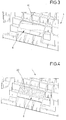
- Fig. 3 shows the area of the deck 2 of the Fig. 2 in a perspective view from below. It can be seen that the mentioned connecting channel, here denoted by 19, extends from the upper side of the deck 2 to the underside of the upper edge 6 and opens there.
- a portion of the molding, which limits the upper edge 6 of the body 1, is movably mounted within this molding and is slightly removed from the body 1 before the coating material is injected into a gap, the is provided at the top of the deck 2 and there forms the slip-resistant coating 10.
- slip-resistant material passes through the connecting channel 19 from the surface of the deck 2 in the gap, which between the upper edge 6 and the movable portion of the molding is created, so that simultaneously with the application of the slip-resistant coating 10 on the deck 2, an anti-slip layer 20 is provided on the underside of the upper edge 6, in Fig. 4 is apparent.
- the connecting channel 19 Through the connecting channel 19, the slip-resistant coating 10 and the anti-slip layer 20 are connected to each other, so that in addition to their respective cohesive connection with the base body 1, a positive connection is created.
Landscapes
- Engineering & Computer Science (AREA)
- Mechanical Engineering (AREA)
- Manufacturing & Machinery (AREA)
- Pallets (AREA)
Description
- Die Erfindung betrifft eine Palette nach Anspruch 1 sowie ein Verfahren zum Herstellen einer Palette.
- Aus der
DE 25 54 210 A1 oder aus derDE 83 10 685 U1 ist die rutschhemmende Ausgestaltung von Paletten grundsätzlich bekannt: Bei diesen Paletten sind die Decks mit eingesetzten Stopfen aus einem Elastomermaterial versehen. Um einen möglichst durchgängigen Effekt der rutschhemmenden Ausgestaltung auf dem Deck zu ermöglichen, müssen derartige Stopfen nahe benachbart zueinander angeordnet werden, so dass auch kleinere Gebinde zuverlässig auf einem rutschhemmend ausgestalteten Bereich des Decks aufstehen und nicht etwa ausschließlich zwischen den Stopfen. Der Aufwand zur Herstellung derartiger Paletten ist vergleichsweise hoch, weil erstens hinsichtlich des Materialaufwands ein erheblicher Teil des rutschhemmenden Elastomermaterials nicht an der Oberfläche des Decks wirksam ist und als Rutschhemmung nutzbar ist, sondern den Körper des jeweiligen Stopfens bildet, und weil zweitens hinsichtlich des Montageaufwands die Vielzahl der Stopfen in den zuvor hergestellten Grundkörper der Palette eingesetzt werden muss. - Zudem ist es aus der
DE 25 54 210 A1 bekannt, dass die rutschhemmende Wirkung durch eine Beschichtung auf dem Grundkörper der Palette erzielt werden kann. - Aus der Praxis ist es bekannt, dass die Beschichtung auf den Grundkörper der Palette auf unterschiedliche Art und Weise aufgebracht werden kann: flächige Beschichtungen können auf den Grundkörper einer Palette aufgeschweißt werden, beispielsweise indem zunächst coextrudierte Platten hergestellt werden, die ihrerseits zweischichtig aufgebaut sind. Auf der Oberseite weisen sie die gewünschten rutschhemmende Schicht auf und die Unterseite einer solchen coextrudierten Platte besteht aus einem Material, welches mit dem Grundkörper der Palette gut verschweißbar ist. Diese Herstellung ist vergleichsweise aufwendig.
- Alternativ ist es bekannt, ein rutschhemmendes Beschichtungsmaterial unmittelbar auf das Palettendeck zu extrudieren. Bei diesem so genannten Aufextrudieren handelt es sich um ein grundsätzlich kontinuierliches Verfahren, welches bei anderen Produkten sehr vorteilhaft angewendet wird, welches bei Paletten jedoch aufgrund deren beschränkter Abmessungen diskontinuierlich durchgeführt werden muss, wobei jeweils die Anfangs- und die Endungs-Stellen beim Auftrag des aufextrudierten Material verfahrenstechnisch problematisch sind. Die Extrusion erfolgt üblicherweise in Streifen. Um einen sicheren Stand für auf der Palette befindliche Güter der verschiedensten Größen sicherzustellen, müssen die Streifen in einem geringen Abstand zueinander auf das Deck des Grundkörpers extrudiert werden. Dementsprechend viele Anfangs- und Endungs-Stellen der diskontinuierlichen Extrusionsvorgänge ergeben sich bei der Herstellung einer Palette und bewirken eine vergleichsweise unwirtschaftliche Verfahrensweise, da jeweils der Extrusionsvorgang angehalten und für die nächste Palette wieder erneut angefahren werden muss.
- Als weitere Alternative ist es bekannt, in einem Mehrkomponenten-Spritzgießverfahren in einem ersten Verfahrensschritt den Grundkörper zu schaffen. Dabei ist eine vergleichsweise komplizierte Gießform mit einer Vielzahl von Einspritzstellen für das rutschhemmende Material erforderlich, um angesichts einer gewünschten geringen Schichtdicke sicherzustellen, dass sich dieses rutschhemmende Material möglichst vollständig und möglichst großflächig auf dem Palettendeck verteilt, ohne vorzeitig zu erstarren. Alternativ kann vorgesehen sein, in diesem Mehrkomponenten-Spritzgießverfahren eine Vielzahl einzelner, nicht zusammenhängender Stellen auf der Oberseite des Palettendecks rutschhemmend auszugestalten, wobei auch bei dieser Ausgestaltung eine Vielzahl von Angüssen bzw. Einspritzkanälen für das rutschhemmende Material vorgesehen sein müsste.
- Aus der
US 5 809 905 A ist eine Palette nach dem Oberbegriff des Anspruchs 1 bekannt. Die rutschhemmende Wirkung wird durch Einsätze erzielt, welche in Öffnungen der Palette eingesetzt werden. - Auch aus der
DE 20 2011 003 697 U1 , derUS 5 453 236 A , derDE 84 07 010 U1 ,GB 1 540 679 A DE 10 2005 003 725 A1 sind Paletten bekannt, die rutschhemmend ausgestaltet sind. - Der Erfindung liegt die Aufgabe zugrunde, eine Palette zu schaffen, die mit einem möglichst geringen Einsatz an rutschhemmendem Material eine möglichst sichere Handhabung der Palette ermöglicht, wobei das rutschhemmende Material zuverlässig mit dem Grundkörper verbunden ist. Weiterhin liegt der Erfindung die Aufgabe zugrunde, ein geeignetes Verfahren zur Herstellung einer solchen Palette anzugeben.
- Diese Aufgabe wird durch eine Palette mit den Merkmalen des Anspruchs 1 gelöst. Vorteilhafte Ausgestaltungen sind in den Unteransprüchen beschrieben. Ein geeignetes Verfahren für die Herstellung einer solchen Palette ist in Anspruch 7 beschrieben.
- Paletten weisen so genannte Einfahröffnungen auf, in welche die Zinken der Gabel eines Flurförderfahrzeugs eingeschoben werden können. Bei einer besonders schnellen Handhabung der Paletten in der täglichen Praxis, mit starken Beschleunigungs- und Bremskräften, kann es beim Abbremsen der Flurförderfahrzeuge dazu kommen, dass die Paletten aufgrund der Massenträgheit von der Gabel des Flurförderfahrzeugs zu rutschen drohen, bevor die Gabel vollständig abgesenkt und die Palette auf dem Untergrund abgestellt ist. Die Erfindung schlägt eine rutschhemmende Wirkung nicht nur auf dem Deck der Palette, sondern auch zwischen der Palette und dem Flurförderfahrzeug vor. Aus diesem Grund ist an dem oberen Rand einer Einfahröffnung die Unterseite dieses oberen Randes rutschhemmend beschichtet, wobei diese Schicht zur sprachlichen Unterscheidung von der so genannten "rutschhemmenden Beschichtung" auf dem Palettendeck als so genannte "Anti-Rutsch-Schicht" bezeichnet ist.
- Die rutschhemmende Beschichtung sowie die Anti-Rutsch-Schicht bestehen aus dem gleichen Material und sind durch einen Verbindungskanal miteinander verbunden, der sich durch den Grundkörper der Palette erstreckt und der mit diesem rutschhemmenden Material gefüllt ist. Auf diese Weise wird eine besonders wirtschaftliche Herstellung der Palette unterstützt, indem die Beschichtung auf der Oberseite des Decks und die Anti-Rutsch-Schicht in der Einfahröffnung gleichzeitig im selben Spritzgießvorgang hergestellt werden können. Das rutschhemmende Material, welches die rutschhemmende Beschichtung und die Anti-Rutsch-Schicht bildet, stammt aus derselben Kunststofffamilie wie der Grundkörper der Palette. Auf diese Weise ist eine stoffschlüssige Verbindung zwischen dem rutschhemmenden Material und dem Grundkörper möglich, so dass die rutschhemmende Beschichtung und die Anti-Rutsch-Schicht hervorragend gegen ablösende Kräfte, wie z. B. Scherkräfte o. dgl. geschützt sind, die bestrebt sind, das rutschhemmende Material vom Grundkörper der Palette abzulösen. Weiterhin ergibt sich durch diese Materialwahl die Möglichkeit, das rutschhemmende Material mit dem Material des Grundkörpers zu mischen, so dass erstens eine hervorragende und hoch belastbare Verbindung mit dem Grundkörper der Palette erzielbar ist und zudem die rutschhemmende Wirkung stufenlos eingestellt und an die jeweiligen Anforderungen angepasst werden kann. Eine zu starke rutschhemmende Wirkung auf dem Palettendeck ist in der Praxis beispielsweise hinderlich, wenn Material auf das Palettendeck geschoben werden soll.
- Vorteilhaft kann vorgesehen sein, dass das rutschhemmende Material eine Schichtdicke von lediglich 0,1 bis 2 mm aufweist, so dass Material eingespart wird und somit die Herstellungskosten der Palette vorteilhaft beeinflusst werden. Dies gilt angesichts der vergleichsweise großen Fläche insbesondere für die rutschhemmende Beschichtung auf dem Deck der Palette, während die im Vergleich dazu erheblich geringere Fläche der Anti-Rutsch-Schicht an der Einfahröffnung eine größere Schichtdicke aufweisen kann, z. B. um eine einfacheres und wirtschaftlicheres Herstellungsverfahren im Bereich dieser Anti-Rutsch-Schicht zu nutzen.
- Die dünne Schichtdicke der vergleichsweise großflächigen rutschhemmenden Beschichtung auf dem Deck der Palette sowie gegebenenfalls auch der Anti-Rutsch-Schicht sind dadurch erzielbar, dass die Beschichtung im so genannten Spritzprägeverfahren aufgebracht wird. Dieses Verfahren wird am Beispiel der rutschhemmenden Beschichtung erläutert: Zunächst wird der Grundkörper als so genannter Vorspritzling hergestellt, und zwar im Spritzgießverfahren. Ein erstes Formteil begrenzt die Fläche des Decks des Grundkörpers. Nachdem der Vorspritzling ausreichend erstarrt ist, wird dieses erste Formteil entfernt, so dass der Vorspritzling in einem zweite Formteil nach wie vor gehalten wird und mit diesem gegen ein drittes Formteil gebracht werden kann, welches sich im Abstand von der Fläche des Decks des Vorspritzlings befindet. Es verbleibt also ein Spalt zwischen dieser Deck-Oberfläche des Grundkörpers bzw. Vorspritzlings und dem erwähnten dritten Formteil. Die Spaltbreite dieses Spalts ist dabei größer als die Schichtdicke der herzustellenden rutschhemmenden Beschichtung. Das zweite Kunststoffmaterial, welches die rutschhemmende Beschichtung bildet, wird in diesen Spalt eingebracht, und anschließend werden die beiden Formteile, also das dritte, zunächst im Abstand vom Deck befindliche Formteil, sowie das erste, den Vorspritzling haltende Formteil, zueinander bewegt, so dass dabei die Spaltbreite verringert wird. Das im Spalt befindliche Material wird hierdurch über die gesamte Spaltfläche verteilt, bis die endgültige Spaltbreite erzielt ist, die der gewünschten Schichtdicke der rutschhemmenden Beschichtung entspricht. Gleichzeitig kann durch diese Verringerung der Spaltbreite das rutschhemmende Material durch den Verbindungskanal in den Bereich der Einfahröffnung gedrückt werden, um dort an der Unterseite des oberen Randes der Einfahröffnung die Anti-Rutsch-Schicht zu bilden. Durch die Spritzprägetechnik lassen sich Materialien als rutschhemmende Beschichtung mit geringer Schichtstärke verarbeiten, die beispielsweise lebensmittelrechtlich unbedenklich sind und zudem aus derselben Kunststofffamilie stammen wie der Grundkörper der Palette.
- Für das Aufbringen der Anti-Rutsch-Schicht auf den Grundkörper kann beispielsweise im so genannten Core-Back-Verfahren ein Bereich der Spritzgießform, der den Grundkörper begrenzt, vom Grundkörper zurückgezogen werden, um so einen Hohlraum zu schaffen, in den das rutschhemmende Material eingespritzt werden kann. Eine anschließende Pressbewegung wie beim Spritzprägeverfahren ist dabei nicht vorgesehen, so dass die Spritzgießform möglichst wirtschaftlich ausgestaltet und die Prozesssteuerung möglichst einfach gehalten werden kann. Die Fließwege des eingespritzten rutschhemmenden Materials im Hohlraum, der für die Anti-Rutsch-Schicht vorgesehen ist, sind erheblich kürzer als auf dem Deck des Grundkörpers für die rutschhemmende Beschichtung, so dass es des Prägevorgangs nicht bedarf.
- Dadurch, dass das Beschichtungsmaterial bei dem Spritzprägeverfahren zunächst in einen vergleichsweise breiten Spalt eingespritzt wird, kann dieser Einspritzvorgang mit vergleichsweise geringem Druck erfolgen, denn der Druck muss nicht so hoch sein, dass sich das Schichtungsmaterial vollflächig über den gesamten Spalt verteilt. Diese Verteilung wird erst anschließend während der Verringerung der Spaltbreite bewirkt. Insbesondere wenn von vornherein der Spalt eine so geringe Spaltbreite aufweisen würde, wie sie der herzustellenden Schichtdicke der rutschhemmenden Beschichtung entsprechen würde, wäre ein Einspritzvorgang mit erheblichem Druck erforderlich, was erhebliche Anforderungen an Spritzgießmaschinen stellt.
- Vorteilhaft kann an den umlaufenden Kanten das rutschhemmende Material gegen Beschädigungen, z. B. gegen abscherende oder abschälende Einwirkungen durch einen Rahmen geschützt sein, der durch den Grundkörper geschaffen wird. Insbesondere die Anti-Rutsch-Schicht ist derartigen Belastungen ausgesetzt, da sie sich an einer Einfahröffnung befindet. Um den erwähnten Rahmen zu bilden, ragt der Grundkörper entlang dem Umfang der Fläche, die mit dem rutschhemmenden Material beschichtet werden soll, nach außen vor, im Bereich des Decks beispielsweise nach oben. Auf diese Weise wird an der Oberfläche des Grundkörpers eine Mulde geschaffen, die mit dem rutschhemmenden Material ausgefüllt werden kann.
- Der Rahmen erstreckt sich vorteilhaft nicht über die gesamte Höhe des rutschhemmenden Materials. So ist auch angesichts von Herstellungstoleranzen, die zu einem vergleichsweise hohen Rahmen und einer vergleichsweise dünnen rutschhemmenden Beschichtung führen könnten, gewährleistet, dass auch große Gegenstände, die auf das Palettendeck gestellt werden, gegen Rutschen gesichert sind. Es ist nämlich sichergestellt, dass diese Gegenstände nicht auf dem Rahmen aufstehen, sondern vielmehr auf der rutschhemmenden Beschichtung, die eine größere Schichtstärke aufweist und sich höher erstreckt als der Rahmen. Der Rahmen schützt das rutschhemmende Material gegen die erwähnten abscherenden oder abschälenden Einwirkungen, indem er den Grenzbereich seitlich abdeckt, in welchem das rutschhemmende Material an das Material des Grundkörpers grenzt.
- Angesichts der geringen Schichtdicke, die vorteilhaft vorgesehen sein kann und angesichts dessen, dass bis auf die Öffnungen und die Rahmen die Palettenoberfläche großflächig rutschhemmend ausgestaltet sein kann, kann bei einem geringem Materialeinsatz an rutschhemmendem Material eine hervorragende, nahezu vollflächige Transportsicherung für auf der Palette aufstehendes Gut durch die nahezu vollflächige rutschhemmende Wirkung auf der Oberseite der Palette gewährleistet werden. Da die rutschhemmende Beschichtung sowie die Anti-Rutsch-Schicht jeweils durch den erwähnten Rahmen eingefasst und gegen seitliche Beschädigungen geschützt sein kann, wird auch bei einer geringen Schichtdicke der Beschichtung eine langlebige Ausgestaltung der Palette ermöglicht.
- Alternativ kann jedoch vorgesehen sein, auf der Oberseite der Palette lediglich eine besonders relevante Bereiche rutschhemmend auszugestalten und nur in diesen Bereichen rutschhemmendes Material auf den Grundkörper aufzubringen. Einer dieser Bereiche schließt an den Verbindungskanal an, der zur Unterseite des oberen Randes einer Einfahröffnung führt. Die auf einige Streifen oder Punkte beschränkte rutschhemmende Beschichtung kann beispielsweise Material sparend dann vorgesehen sein, wenn eine Palette für einen bestimmten Einsatzzweck bestimmt ist und an eine bestimmte, vorgegebene Formgebung der zu transportierenden Güter angepasst werden kann.
- Vorteilhaft kann die Schichtdicke des rutschhemmenden Materials etwa 0,5 mm betragen, so dass einerseits eine ausreichend verschleißfeste und dementsprechend langlebige Beschichtung, sowie andererseits ein möglichst geringer Einsatz an rutschhemmendem Material miteinander kombiniert sind. Diese Schichtdicke ist auch ausreichend, um einerseits eine haltbare stoffschlüssige Verbindung mit dem Grundkörper der Palette zu ermöglichen und andererseits die rutschhemmende Wirkung ohne Beeinträchtigung durch das weniger rutschhemmende Material des Grundkörpers der Palette sicherstellen zu können. Insbesondere auf dem Palettendeck kann diese geringe Schichtdicke der rutschhemmenden Beschichtung vorteilhaft sein, während in der Einfahröffnung die Anti-Rutsch-Schicht eine Schichtdicke von mehreren Millimetern aufweisen kann, beispielsweise 2 bis 4 mm.
- Der Grundkörper und das rutschhemmende Material können vorteilhaft aus einem Olefin-Material bestehen. Die Gruppe der Olefine stellt eine Kunststofffamilie dar, bei der die einzelnen Kunststoffe einerseits die für den Grundkörper der Palette gewünschten Eigenschaften bereitstellen, beispielsweise was mechanische Stabilität angeht, als auch die für die Beschichtung gewünschten Eigenschaften, nämlich rutschhemmend zu wirken. Zudem können aus der Familie der Olefin-Kunststoffe lebensmittelverträgliche Kunststoffe ausgewählt werden, so dass entsprechende Anforderungen an eine Palette, die im Lebensmittel verarbeitenden Bereich eingesetzt werden soll, problemlos erfüllt werden können.
- Beispielsweise kann der Grundkörper vorteilhaft aus einem Polyethylen oder aus einem Polypropylen bestehen und das rutschhemmende Material kann ein Olefin-Block-Copolymer sein.
- Bei dem bereits erläuterten Herstellungsverfahren für die Herstellung einer vorschlagsgemäßen Palette kann die gleichzeitige Herstellung der rutschhemmenden Beschichtung auf der Oberseite des Decks sowie der Anti-Rutsch-Schicht in der Einfahrtasche dadurch erfolgen, dass an dem erwähnten ersten Formteil, welches den Vorspritzling hält, ein Teil zurückgezogen wird, der die spätere Unterseite des oberen Randes einer Einfahröffnung begrenzt. Auf diese Weise wird ein Spalt zwischen dieser Unterseite und dem ersten Formteil geschaffen. Ein Kern der Spritzgießform wird aus dem Vorspritzling entfernt, so dass ein Verbindungskanal zwischen dem erwähnten Spalt an der Einfahrtasche und dem bereits weiter oben erwähnten ersten Spalt geschaffen wird, der an dem Deck des Grundkörpers vorgesehen ist. Durch die Entfernung des Kerns und die Schaffung des erwähnten Verbindungskanals werden die beiden Spalten miteinander verbunden, so dass beim Einspritzen des rutschhemmenden Materials in den ersten Spalt, spätestens aber beim Spritzprägen, wenn die Spaltbreite des ersten Spalts verringert wird, rutschhemmendes Material vom ersten Spalt durch den Verbindungskanal in den zweiten Spalt fließt, der an der Unterseite des oberen Randes der Einfahröffnung vorgesehen ist. Bei diesem Einspritzvorgang wird also die rutschhemmende Beschichtung auf dem Deck der Palette sowie die Anti-Rutsch-Schicht an der Unterseite des oberen Randes der Einfahröffnung in einem einzigen Verfahrensschritt geschaffen, so dass eine möglichst wirtschaftliche Herstellung der Palette unterstützt wird.
- Ein Ausführungsbeispiel der Erfindung wird anhand der rein schematischen Darstellungen nachfolgend näher erläutert. Dabei zeigt
- Fig. 1
- eine Palette in perspektivischer Ansicht,
- Fig. 2
- eine perspektivische Ansicht auf den Ausschnitt eines Grundkörpers eines Palettendecks im Bereich einer Einfahröffnung,
- Fig. 3
- eine Ansicht perspektivisch von unten auf den Bereich von
Fig. 2 , und - Fig. 4
- eine Ansicht wie
Fig. 3 , wobei jedoch der Grundkörper mit einer Anti-Rutsch-Schicht versehen ist. - In
Fig. 1 ist ein Grundkörper 1 einer Palette 9 dargestellt, wobei die Palette 9 eine als Deck 2 bezeichnete Oberseite aufweist, sowie zwei Einfahröffnungen 3 und mehrere Füße 4. Jede Einfahröffnung 3 ist allseitig umrandet, wobei zwei Füße 4 die beiden seitlichen Ränder einer Einfahröffnung 3 bilden und diese Füße 4 zu Kufen miteinander verbunden sind, so dass diese Kufen den jeweils unteren Rand 5 einer Einfahröffnung 3 bilden. Ein oberer Rand 6 der Einfahröffnung 3 wird durch die Unterseite des Decks 2 gebildet. - Das Deck 2 ist im Wesentlichen geschlossen ausgestaltet, weist jedoch in seinem mittleren Bereich zwei gitterartig ausgestaltete Öffnungen 7 auf. Um die Öffnungen 7 herum sowie entlang dem äußeren Umfang des Decks 2 verlaufen jeweils Rahmen 8, die sich gegenüber der übrigen Oberfläche des Decks 2 geringfügig nach oben erstrecken.
- Auf der Oberseite des Decks 2 ist eine rutschhemmende Beschichtung 10 vorgesehen. Die Beschichtung 10 und der Grundkörper 1 bestehen aus unterschiedlichen Kunststoffmaterialien, die jedoch aus derselben Kunststofffamilie bestehen, nämlich jeweils aus einem Olefin-Werkstoff. Die Beschichtung 10 schließt an die Rahmen 8 an, so dass bis auf die Öffnungen 7 ein geschlossenes Deck 2 der Palette 9 geschaffen wird. Das Deck 2 wird folglich größtenteils durch die rutschhemmende Beschichtung 10 gebildet, wobei abweichend von dem dargestellten Ausführungsbeispiel die rutschhemmende Beschichtung 10 auf einige streifenförmige oder punktuelle Bereiche begrenzt sein kann.
-
Fig. 2 zeigt ausschnittsweise eine Ansicht auf einen Grundkörper 1, nämlich auf den Bereich eines Decks 2 oberhalb einer Einfahröffnung 3, wo das Deck 2 den oberen Rand 6 einer Einfahröffnung 3 bildet. Es ist vorgesehen, das Deck 2 mit einer rutschhemmenden Beschichtung 10 zu versehen, und der Rahmen 8 ist erkennbar, der sich gegenüber dem übrigen Deck 2 des Grundkörpers 1 geringfügig nach oben erstreckt. Im Deck 2 ist eine Mündung 18 erkennbar, die das obere Ende eines Verbindungskanals bildet. -
Fig. 3 zeigt den Bereich des Decks 2 derFig. 2 in einer perspektivischen Ansicht von unten. Es ist erkennbar, dass der erwähnte Verbindungskanal, hier mit 19 gekennzeichnet, von der Oberseite des Decks 2 bis an die Unterseite des oberen Randes 6 verläuft und dort mündet. - Bei der Herstellung der Palette 9 ist vorgesehen, dass ein Abschnitt des Formteils, welcher nämlich den oberen Rand 6 des Grundkörpers 1 begrenzt, innerhalb dieses Formteils beweglich gelagert ist und vom Grundkörper 1 geringfügig entfernt wird, bevor das Beschichtungsmaterial in einen Spalt eingespritzt wird, der an der Oberseite des Decks 2 vorgesehen ist und dort die rutschhemmende Beschichtung 10 bildet. Bei diesem Einspritzvorgang oder spätestens bei dem anschließenden Prägevorgang, wenn nämlich die Spaltbreite des erwähnten Spaltes an der Oberseite des Decks 2 verringert wird, gelangt rutschhemmendes Material durch den Verbindungskanal 19 von der Oberfläche des Decks 2 in den Spalt, welcher zwischen dem oberen Rand 6 und dem beweglichen Abschnitt des Formteils geschaffen ist, so dass gleichzeitig mit der Aufbringung der rutschhemmenden Beschichtung 10 auf dem Deck 2 auch eine Anti-Rutsch-Schicht 20 an der Unterseite des oberen Randes 6 geschaffen wird, die in
Fig. 4 ersichtlich ist. Durch den Verbindungskanal 19 sind die rutschhemmende Beschichtung 10 und die Anti-Rutsch-Schicht 20 miteinander verbunden, so dass zusätzlich zu deren jeweils stoffschlüssigen Verbindung mit dem Grundkörper 1 auch ein Formschluss geschaffen wird.
Claims (7)
- Palette (9),
mit einem Grundkörper (1) aus einem Kunststoffmaterial, einem Deck (2), das die Oberseite der Palette (9) bildet, einer auf der Oberseite des Decks (2) vorgesehenen rutschhemmenden Beschichtung (10),
und Einfahröffnungen (3) zur Aufnahme der Gabel eines Flurförderfahrzeugs,
wobei eine Einfahröffnung (3) einen oberen Rand (6) aufweist, der von der Gabel unterfahrbar ist,
dieser obere Rand (6) an seiner Unterseite mit einer Anti-Rutsch-Schicht (20) versehen ist,
dadurch gekennzeichnet,
dass die rutschhemmende Beschichtung (10) und die Anti-Rutsch-Schicht (20) aus demselben rutschhemmenden Material bestehen und durch einen mit diesem Material gefüllten Verbindungskanal (19) miteinander verbunden sind, das rutschhemmende Material aus der selben Kunststofffamilie wie der Grundkörper (1) besteht,
und wobei die rutschhemmende Beschichtung (10) und die Anti-Rutsch-Schicht (20) als gleichzeitig hergestellte Bereiche eines Spritzkörpers geschaffen sind, der sowohl stoffschlüssig als auch formschlüssig mit dem Grundkörper (1) verbunden ist. - Palette nach Anspruch 1,
dadurch gekennzeichnet,
dass der Grundkörper (1) einen Rahmen (8) bildet, der das rutschhemmende Material begrenzt. - Palette nach Anspruch 1 oder 2,
dadurch gekennzeichnet,
dass die Anti-Rutsch-Schicht (20) eine Schichtdicke von 0,1 mm bis 4 mm aufweist. - Palette nach einem der vorhergehenden Ansprüche,
dadurch gekennzeichnet,
dass der Grundkörper (1) und das rutschhemmende Material aus einem Olefinmaterial bestehen. - Palette nach Anspruch 4,
dadurch gekennzeichnet,
dass der Grundkörper (1) aus einem Polyethylen- oder Polypropylenmaterial besteht. - Palette nach Anspruch 4,
dadurch gekennzeichnet,
dass das rutschhemmende Material aus einem Olefin-Block-Copolymer besteht. - Verfahren zum Herstellen einer Palette (9),
wobei ein Grundkörper (1) mit einem Deck (2) aus einem ersten Kunststoffmaterial im Spritzgießverfahren hergestellt wird,
dadurch gekennzeichnet,
dass der Grundkörper (1) als Vorspritzling hergestellt wird, wobei die Fläche des Decks (2) durch ein erstes Formteil begrenzt wird,
und anschließend ein den Vorspritzling haltendes zweites Formteil gegen ein drittes Formteil gebracht wird, welches sich im Abstand von der Fläche des Decks (2) des Vorspritzlings befindet, derart, dass ein Spalt zwischen der Fläche des Decks (2) und dem dritten Formteil verbleibt,
und wobei anschließend ein zweites Kunststoffmaterial, welches aus der selben Kunststofffamilie stammt wie das erste Kunststoffmaterial des Grundkörpers (1), als rutschhemmende Beschichtung (10) im Spritzprägeverfahren in den Spalt eingebracht wird,
und vor der Erstarrung des zweiten Kunststoffmaterials das zweite Formteil und das dritte Formteil relativ zueinander bewegt werden, derart, dass die Spaltbreite des Spalts verringert wird,
wobei ein Teil des zweiten Formteils, welcher die spätere Unterseite eines oberen Randes (6) einer Einfahröffnung (3) des Vorspritzlings begrenzt, zurückgezogen wird, derart, dass ein zweiter Spalt zwischen dieser Unterseite und dem zweiten Formteil geschaffen wird,
und dass ein Kern aus dem Vorspritzling entfernt wird, derart, dass ein Verbindungskanal (19) zwischen dem ersten Spalt und dem zweiten Spalt geschaffen wird,
und dass das zweite Kunststoffmaterial in den ersten Spalt und durch den Verbindungskanal (19) in den zweiten Spalt eingespritzt wird,
derart, dass bei diesem Einspritzvorgang die rutschhemmende Beschichtung (10) auf dem Deck (2) der Palette (9) sowie eine Anti-Rutsch-Schicht (20) an der Unterseite des oberen Randes (6) der Einfahröffnung (3) geschaffen wird.
Priority Applications (1)
| Application Number | Priority Date | Filing Date | Title |
|---|---|---|---|
| PL14805282T PL3077298T3 (pl) | 2013-12-02 | 2014-11-28 | Paleta z otworem do wsuwania powleczonym w sposób hamujący poślizg |
Applications Claiming Priority (2)
| Application Number | Priority Date | Filing Date | Title |
|---|---|---|---|
| DE102013113336.3A DE102013113336A1 (de) | 2013-12-02 | 2013-12-02 | Palette mit rutschhemmend beschichteter Einfahröffnung |
| PCT/EP2014/075999 WO2015082359A1 (de) | 2013-12-02 | 2014-11-28 | Palette mit rutschhemmend beschichteter einfahröffnung |
Publications (2)
| Publication Number | Publication Date |
|---|---|
| EP3077298A1 EP3077298A1 (de) | 2016-10-12 |
| EP3077298B1 true EP3077298B1 (de) | 2017-10-18 |
Family
ID=51999438
Family Applications (1)
| Application Number | Title | Priority Date | Filing Date |
|---|---|---|---|
| EP14805282.2A Active EP3077298B1 (de) | 2013-12-02 | 2014-11-28 | Palette mit rutschhemmend beschichteter einfahröffnung |
Country Status (8)
| Country | Link |
|---|---|
| EP (1) | EP3077298B1 (de) |
| DE (1) | DE102013113336A1 (de) |
| DK (1) | DK3077298T3 (de) |
| ES (1) | ES2656197T3 (de) |
| NO (1) | NO3120131T3 (de) |
| PL (1) | PL3077298T3 (de) |
| PT (1) | PT3077298T (de) |
| WO (1) | WO2015082359A1 (de) |
Families Citing this family (3)
| Publication number | Priority date | Publication date | Assignee | Title |
|---|---|---|---|---|
| CH714201A1 (de) * | 2017-09-29 | 2019-03-29 | Wrh Walter Reist Holding Ag | Träger zum Transport von Transportgut, mit einer Trägerstruktur zum Tragen des Transportgutes auf einer horizontalen Trägerebene. |
| DE202018102877U1 (de) | 2018-05-23 | 2018-07-03 | Paul Craemer Gmbh | Vielfältig handhabbare Kunststoffpalette |
| CN115848774A (zh) * | 2022-01-19 | 2023-03-28 | 上海箱箱智能科技有限公司 | 托盘 |
Family Cites Families (8)
| Publication number | Priority date | Publication date | Assignee | Title |
|---|---|---|---|---|
| GB1512450A (en) * | 1975-05-06 | 1978-06-01 | Mitsubishi Chem Ind | Plastics pallet |
| GB1540679A (en) * | 1976-03-29 | 1979-02-14 | Nippon Petrochemicals Co Ltd | Thermoplastic resin pallet or pallet part with antiskid member and method for the manufacture thereof |
| DE8310685U1 (de) * | 1983-04-12 | 1983-07-28 | Paul Craemer GmbH, 4836 Herzebrock | Kunststoffpalette mit Gummistopfen |
| DE8407010U1 (de) * | 1984-03-07 | 1984-04-26 | Brand, geb. Reckordt, Irmgard, 4836 Herzebrock | Transportpalette |
| US5453236A (en) * | 1994-02-08 | 1995-09-26 | Composite Design International, Inc. | Method of molding a load bearing pallet from recycled materials |
| US5809905A (en) * | 1995-09-05 | 1998-09-22 | Plastic Pallet Production, Inc. | Vertical interlocking modular pallet apparatus and method of construction |
| DE102005003725A1 (de) * | 2005-01-26 | 2006-07-27 | Linpac Materials Handling(Germany)Gmbh | Rutschhemmende Beschichtung eines Transportkastens einer Palette oder eines Tablars aus Kunststoff und Verfahren zu deren Herstellung |
| DE202011003697U1 (de) * | 2011-03-09 | 2011-05-19 | KIGA-Kunststofftechnik GmbH, 57234 | Palette sowie Platte zur Auflage auf die Oberfläche des Palettendecks einer Palette |
-
2013
- 2013-12-02 DE DE102013113336.3A patent/DE102013113336A1/de not_active Withdrawn
-
2014
- 2014-11-28 DK DK14805282.2T patent/DK3077298T3/en active
- 2014-11-28 EP EP14805282.2A patent/EP3077298B1/de active Active
- 2014-11-28 WO PCT/EP2014/075999 patent/WO2015082359A1/de not_active Ceased
- 2014-11-28 PT PT148052822T patent/PT3077298T/pt unknown
- 2014-11-28 PL PL14805282T patent/PL3077298T3/pl unknown
- 2014-11-28 ES ES14805282.2T patent/ES2656197T3/es active Active
-
2015
- 2015-03-10 NO NO15712737A patent/NO3120131T3/no unknown
Non-Patent Citations (1)
| Title |
|---|
| None * |
Also Published As
| Publication number | Publication date |
|---|---|
| WO2015082359A1 (de) | 2015-06-11 |
| NO3120131T3 (de) | 2018-06-09 |
| PL3077298T3 (pl) | 2018-03-30 |
| DK3077298T3 (en) | 2018-01-22 |
| PT3077298T (pt) | 2018-01-25 |
| ES2656197T3 (es) | 2018-02-26 |
| DE102013113336A1 (de) | 2015-06-03 |
| EP3077298A1 (de) | 2016-10-12 |
Similar Documents
| Publication | Publication Date | Title |
|---|---|---|
| DE2554210A1 (de) | Kunststoffpalette | |
| DE102007039126A1 (de) | Verbundplatte und Verfahren zu ihrer Herstellung | |
| EP1923317B1 (de) | Kunststoffpalette mit gleithemmend beschichteter Beladefläche | |
| DE2123472A1 (de) | Unter Anwendung von Spritzguß hergestellter Behälter sowie Verfahren zu seiner Herstellung | |
| EP3178624B1 (de) | Vorrichtung und verfahren zur herstellung von verbundformteilen | |
| WO2015082359A1 (de) | Palette mit rutschhemmend beschichteter einfahröffnung | |
| DE19522000C2 (de) | Kunststoffpalette | |
| WO2014094978A1 (de) | Verfahren zum herstellen eines kunststoff-formteils sowie spritzgiessmaschine | |
| EP3285983B1 (de) | Verfahren zum herstellen eines mehrteiligen kunststoffbauteils sowie mehrteiliges kunststoffbauteil | |
| DE69510805T2 (de) | Verfahren zum herstellen einer platte beschichtet mit einer verblendungsfläche, insbesondere textil | |
| DE202013012399U1 (de) | Palette mit rutschhemmender Oberseite | |
| EP3188975B1 (de) | Ladegutträger | |
| DE102013114753A1 (de) | Verfahren zur Herstellung von Dauerbackware sowie Dauerbackware | |
| DE2523688C2 (de) | Spritzgießverfahren zum Herstellen eines zusammengesetzten Erzeugnisses und Spritzgießform zur Durchführung des Verfahrens | |
| EP3844052B1 (de) | System zu dämmung eines strukturelementes | |
| EP2674027A2 (de) | Bodenbelagsplatte | |
| DE3834535A1 (de) | Verfahren und vorrichtung zum umhuellen von stueckgutstapeln mit kunststoffolie | |
| WO2017162331A1 (de) | Kunststoff-bauteil mit zumindest einer elektrischen leiterbahn und verfahren zu seiner herstellung | |
| DE3644144C2 (de) | ||
| DE1771185A1 (de) | Verfahren zur Anbringung von Trennorganen zwischen Elektroden verschiedener Polaritaet in einer galvanischen Primaer- oder Sekundaerzelle sowie mit solchen Trennorganen versehene Elektroden fuer galvanische Zelle | |
| EP3131730B1 (de) | Verfahren zum überführen von bodenlabeln und banderolenlabeln in eine spritzgiessform und hierfür geeignete vorrichtung zur herstellung von mit bodenlabeln und banderolenlabeln versehenen spritzgussteilen | |
| DE102012221843B4 (de) | Verfahren zur Aufbringung wenigstens eines Haftstreifens auf einer Unterseite eines Palettenbodens aus Kunststoff | |
| DE29720425U1 (de) | Aktenordner mit Aktenordnerkantenschutzstreifen und Aktenordnerkantenschutzstreifen | |
| EP3768522B1 (de) | Postforming-paneel | |
| EP1845023A1 (de) | Palette aus Kunststoff mit geschäumter Deckplatte |
Legal Events
| Date | Code | Title | Description |
|---|---|---|---|
| PUAI | Public reference made under article 153(3) epc to a published international application that has entered the european phase |
Free format text: ORIGINAL CODE: 0009012 |
|
| 17P | Request for examination filed |
Effective date: 20160601 |
|
| AK | Designated contracting states |
Kind code of ref document: A1 Designated state(s): AL AT BE BG CH CY CZ DE DK EE ES FI FR GB GR HR HU IE IS IT LI LT LU LV MC MK MT NL NO PL PT RO RS SE SI SK SM TR |
|
| AX | Request for extension of the european patent |
Extension state: BA ME |
|
| DAX | Request for extension of the european patent (deleted) | ||
| GRAP | Despatch of communication of intention to grant a patent |
Free format text: ORIGINAL CODE: EPIDOSNIGR1 |
|
| RIC1 | Information provided on ipc code assigned before grant |
Ipc: B29C 45/16 20060101ALI20170418BHEP Ipc: B65D 19/24 20060101AFI20170418BHEP |
|
| INTG | Intention to grant announced |
Effective date: 20170516 |
|
| GRAS | Grant fee paid |
Free format text: ORIGINAL CODE: EPIDOSNIGR3 |
|
| GRAA | (expected) grant |
Free format text: ORIGINAL CODE: 0009210 |
|
| AK | Designated contracting states |
Kind code of ref document: B1 Designated state(s): AL AT BE BG CH CY CZ DE DK EE ES FI FR GB GR HR HU IE IS IT LI LT LU LV MC MK MT NL NO PL PT RO RS SE SI SK SM TR |
|
| REG | Reference to a national code |
Ref country code: GB Ref legal event code: FG4D Free format text: NOT ENGLISH |
|
| REG | Reference to a national code |
Ref country code: CH Ref legal event code: EP |
|
| REG | Reference to a national code |
Ref country code: AT Ref legal event code: REF Ref document number: 937712 Country of ref document: AT Kind code of ref document: T Effective date: 20171115 Ref country code: IE Ref legal event code: FG4D Free format text: LANGUAGE OF EP DOCUMENT: GERMAN |
|
| REG | Reference to a national code |
Ref country code: DE Ref legal event code: R096 Ref document number: 502014005895 Country of ref document: DE |
|
| REG | Reference to a national code |
Ref country code: FR Ref legal event code: PLFP Year of fee payment: 4 |
|
| REG | Reference to a national code |
Ref country code: DK Ref legal event code: T3 Effective date: 20180117 |
|
| REG | Reference to a national code |
Ref country code: NL Ref legal event code: FP |
|
| REG | Reference to a national code |
Ref country code: PT Ref legal event code: SC4A Ref document number: 3077298 Country of ref document: PT Date of ref document: 20180125 Kind code of ref document: T Free format text: AVAILABILITY OF NATIONAL TRANSLATION Effective date: 20180117 |
|
| REG | Reference to a national code |
Ref country code: CH Ref legal event code: NV Representative=s name: BRAUNPAT BRAUN EDER AG, CH |
|
| REG | Reference to a national code |
Ref country code: SE Ref legal event code: TRGR |
|
| REG | Reference to a national code |
Ref country code: ES Ref legal event code: FG2A Ref document number: 2656197 Country of ref document: ES Kind code of ref document: T3 Effective date: 20180226 |
|
| REG | Reference to a national code |
Ref country code: LT Ref legal event code: MG4D |
|
| REG | Reference to a national code |
Ref country code: NO Ref legal event code: T2 Effective date: 20171018 |
|
| PG25 | Lapsed in a contracting state [announced via postgrant information from national office to epo] |
Ref country code: FI Free format text: LAPSE BECAUSE OF FAILURE TO SUBMIT A TRANSLATION OF THE DESCRIPTION OR TO PAY THE FEE WITHIN THE PRESCRIBED TIME-LIMIT Effective date: 20171018 Ref country code: LT Free format text: LAPSE BECAUSE OF FAILURE TO SUBMIT A TRANSLATION OF THE DESCRIPTION OR TO PAY THE FEE WITHIN THE PRESCRIBED TIME-LIMIT Effective date: 20171018 |
|
| REG | Reference to a national code |
Ref country code: CH Ref legal event code: PCAR Free format text: NEW ADDRESS: HOLEESTRASSE 87, 4054 BASEL (CH) |
|
| PG25 | Lapsed in a contracting state [announced via postgrant information from national office to epo] |
Ref country code: IS Free format text: LAPSE BECAUSE OF FAILURE TO SUBMIT A TRANSLATION OF THE DESCRIPTION OR TO PAY THE FEE WITHIN THE PRESCRIBED TIME-LIMIT Effective date: 20180218 Ref country code: HR Free format text: LAPSE BECAUSE OF FAILURE TO SUBMIT A TRANSLATION OF THE DESCRIPTION OR TO PAY THE FEE WITHIN THE PRESCRIBED TIME-LIMIT Effective date: 20171018 Ref country code: LV Free format text: LAPSE BECAUSE OF FAILURE TO SUBMIT A TRANSLATION OF THE DESCRIPTION OR TO PAY THE FEE WITHIN THE PRESCRIBED TIME-LIMIT Effective date: 20171018 Ref country code: BG Free format text: LAPSE BECAUSE OF FAILURE TO SUBMIT A TRANSLATION OF THE DESCRIPTION OR TO PAY THE FEE WITHIN THE PRESCRIBED TIME-LIMIT Effective date: 20180118 Ref country code: GR Free format text: LAPSE BECAUSE OF FAILURE TO SUBMIT A TRANSLATION OF THE DESCRIPTION OR TO PAY THE FEE WITHIN THE PRESCRIBED TIME-LIMIT Effective date: 20180119 Ref country code: RS Free format text: LAPSE BECAUSE OF FAILURE TO SUBMIT A TRANSLATION OF THE DESCRIPTION OR TO PAY THE FEE WITHIN THE PRESCRIBED TIME-LIMIT Effective date: 20171018 |
|
| REG | Reference to a national code |
Ref country code: DE Ref legal event code: R097 Ref document number: 502014005895 Country of ref document: DE |
|
| PG25 | Lapsed in a contracting state [announced via postgrant information from national office to epo] |
Ref country code: MC Free format text: LAPSE BECAUSE OF FAILURE TO SUBMIT A TRANSLATION OF THE DESCRIPTION OR TO PAY THE FEE WITHIN THE PRESCRIBED TIME-LIMIT Effective date: 20171018 Ref country code: SK Free format text: LAPSE BECAUSE OF FAILURE TO SUBMIT A TRANSLATION OF THE DESCRIPTION OR TO PAY THE FEE WITHIN THE PRESCRIBED TIME-LIMIT Effective date: 20171018 Ref country code: EE Free format text: LAPSE BECAUSE OF FAILURE TO SUBMIT A TRANSLATION OF THE DESCRIPTION OR TO PAY THE FEE WITHIN THE PRESCRIBED TIME-LIMIT Effective date: 20171018 |
|
| PLBE | No opposition filed within time limit |
Free format text: ORIGINAL CODE: 0009261 |
|
| STAA | Information on the status of an ep patent application or granted ep patent |
Free format text: STATUS: NO OPPOSITION FILED WITHIN TIME LIMIT |
|
| PG25 | Lapsed in a contracting state [announced via postgrant information from national office to epo] |
Ref country code: SM Free format text: LAPSE BECAUSE OF FAILURE TO SUBMIT A TRANSLATION OF THE DESCRIPTION OR TO PAY THE FEE WITHIN THE PRESCRIBED TIME-LIMIT Effective date: 20171018 Ref country code: LU Free format text: LAPSE BECAUSE OF NON-PAYMENT OF DUE FEES Effective date: 20171128 |
|
| 26N | No opposition filed |
Effective date: 20180719 |
|
| PG25 | Lapsed in a contracting state [announced via postgrant information from national office to epo] |
Ref country code: MT Free format text: LAPSE BECAUSE OF FAILURE TO SUBMIT A TRANSLATION OF THE DESCRIPTION OR TO PAY THE FEE WITHIN THE PRESCRIBED TIME-LIMIT Effective date: 20171018 |
|
| PG25 | Lapsed in a contracting state [announced via postgrant information from national office to epo] |
Ref country code: SI Free format text: LAPSE BECAUSE OF FAILURE TO SUBMIT A TRANSLATION OF THE DESCRIPTION OR TO PAY THE FEE WITHIN THE PRESCRIBED TIME-LIMIT Effective date: 20171018 |
|
| PG25 | Lapsed in a contracting state [announced via postgrant information from national office to epo] |
Ref country code: HU Free format text: LAPSE BECAUSE OF FAILURE TO SUBMIT A TRANSLATION OF THE DESCRIPTION OR TO PAY THE FEE WITHIN THE PRESCRIBED TIME-LIMIT; INVALID AB INITIO Effective date: 20141128 |
|
| PG25 | Lapsed in a contracting state [announced via postgrant information from national office to epo] |
Ref country code: RO Free format text: LAPSE BECAUSE OF FAILURE TO SUBMIT A TRANSLATION OF THE DESCRIPTION OR TO PAY THE FEE WITHIN THE PRESCRIBED TIME-LIMIT Effective date: 20171018 |
|
| PG25 | Lapsed in a contracting state [announced via postgrant information from national office to epo] |
Ref country code: CY Free format text: LAPSE BECAUSE OF FAILURE TO SUBMIT A TRANSLATION OF THE DESCRIPTION OR TO PAY THE FEE WITHIN THE PRESCRIBED TIME-LIMIT Effective date: 20171018 |
|
| PG25 | Lapsed in a contracting state [announced via postgrant information from national office to epo] |
Ref country code: MK Free format text: LAPSE BECAUSE OF FAILURE TO SUBMIT A TRANSLATION OF THE DESCRIPTION OR TO PAY THE FEE WITHIN THE PRESCRIBED TIME-LIMIT Effective date: 20171018 |
|
| PG25 | Lapsed in a contracting state [announced via postgrant information from national office to epo] |
Ref country code: TR Free format text: LAPSE BECAUSE OF FAILURE TO SUBMIT A TRANSLATION OF THE DESCRIPTION OR TO PAY THE FEE WITHIN THE PRESCRIBED TIME-LIMIT Effective date: 20171018 |
|
| PG25 | Lapsed in a contracting state [announced via postgrant information from national office to epo] |
Ref country code: AL Free format text: LAPSE BECAUSE OF FAILURE TO SUBMIT A TRANSLATION OF THE DESCRIPTION OR TO PAY THE FEE WITHIN THE PRESCRIBED TIME-LIMIT Effective date: 20171018 |
|
| PGFP | Annual fee paid to national office [announced via postgrant information from national office to epo] |
Ref country code: IE Payment date: 20211118 Year of fee payment: 8 Ref country code: NO Payment date: 20211119 Year of fee payment: 8 Ref country code: DK Payment date: 20211119 Year of fee payment: 8 Ref country code: ES Payment date: 20211216 Year of fee payment: 8 Ref country code: CZ Payment date: 20211118 Year of fee payment: 8 Ref country code: AT Payment date: 20211117 Year of fee payment: 8 Ref country code: PT Payment date: 20211122 Year of fee payment: 8 Ref country code: SE Payment date: 20211123 Year of fee payment: 8 |
|
| PGFP | Annual fee paid to national office [announced via postgrant information from national office to epo] |
Ref country code: IT Payment date: 20211130 Year of fee payment: 8 Ref country code: CH Payment date: 20211123 Year of fee payment: 8 |
|
| PGFP | Annual fee paid to national office [announced via postgrant information from national office to epo] |
Ref country code: PL Payment date: 20211108 Year of fee payment: 8 |
|
| REG | Reference to a national code |
Ref country code: DK Ref legal event code: EBP Effective date: 20221130 |
|
| REG | Reference to a national code |
Ref country code: NO Ref legal event code: MMEP |
|
| REG | Reference to a national code |
Ref country code: CH Ref legal event code: PL |
|
| REG | Reference to a national code |
Ref country code: SE Ref legal event code: EUG |
|
| P01 | Opt-out of the competence of the unified patent court (upc) registered |
Effective date: 20230526 |
|
| REG | Reference to a national code |
Ref country code: AT Ref legal event code: MM01 Ref document number: 937712 Country of ref document: AT Kind code of ref document: T Effective date: 20221128 |
|
| PG25 | Lapsed in a contracting state [announced via postgrant information from national office to epo] |
Ref country code: PT Free format text: LAPSE BECAUSE OF NON-PAYMENT OF DUE FEES Effective date: 20230529 Ref country code: NO Free format text: LAPSE BECAUSE OF NON-PAYMENT OF DUE FEES Effective date: 20221130 Ref country code: LI Free format text: LAPSE BECAUSE OF NON-PAYMENT OF DUE FEES Effective date: 20221130 Ref country code: CZ Free format text: LAPSE BECAUSE OF NON-PAYMENT OF DUE FEES Effective date: 20221128 Ref country code: CH Free format text: LAPSE BECAUSE OF NON-PAYMENT OF DUE FEES Effective date: 20221130 Ref country code: AT Free format text: LAPSE BECAUSE OF NON-PAYMENT OF DUE FEES Effective date: 20221128 |
|
| PG25 | Lapsed in a contracting state [announced via postgrant information from national office to epo] |
Ref country code: SE Free format text: LAPSE BECAUSE OF NON-PAYMENT OF DUE FEES Effective date: 20221129 |
|
| REG | Reference to a national code |
Ref country code: DE Ref legal event code: R082 Ref document number: 502014005895 Country of ref document: DE Representative=s name: PATENTANWAELTE OLBRICHT, BUCHHOLD, KEULERTZ PA, DE |
|
| PG25 | Lapsed in a contracting state [announced via postgrant information from national office to epo] |
Ref country code: IT Free format text: LAPSE BECAUSE OF NON-PAYMENT OF DUE FEES Effective date: 20221128 Ref country code: IE Free format text: LAPSE BECAUSE OF NON-PAYMENT OF DUE FEES Effective date: 20221128 Ref country code: DK Free format text: LAPSE BECAUSE OF NON-PAYMENT OF DUE FEES Effective date: 20221130 |
|
| REG | Reference to a national code |
Ref country code: ES Ref legal event code: FD2A Effective date: 20240105 |
|
| PG25 | Lapsed in a contracting state [announced via postgrant information from national office to epo] |
Ref country code: ES Free format text: LAPSE BECAUSE OF NON-PAYMENT OF DUE FEES Effective date: 20221129 |
|
| PG25 | Lapsed in a contracting state [announced via postgrant information from national office to epo] |
Ref country code: ES Free format text: LAPSE BECAUSE OF NON-PAYMENT OF DUE FEES Effective date: 20221129 |
|
| PG25 | Lapsed in a contracting state [announced via postgrant information from national office to epo] |
Ref country code: PL Free format text: LAPSE BECAUSE OF NON-PAYMENT OF DUE FEES Effective date: 20221128 |
|
| PGFP | Annual fee paid to national office [announced via postgrant information from national office to epo] |
Ref country code: NL Payment date: 20251128 Year of fee payment: 12 |
|
| PGFP | Annual fee paid to national office [announced via postgrant information from national office to epo] |
Ref country code: DE Payment date: 20251130 Year of fee payment: 12 |
|
| PGFP | Annual fee paid to national office [announced via postgrant information from national office to epo] |
Ref country code: GB Payment date: 20251128 Year of fee payment: 12 |
|
| PGFP | Annual fee paid to national office [announced via postgrant information from national office to epo] |
Ref country code: FR Payment date: 20251128 Year of fee payment: 12 |
|
| PGFP | Annual fee paid to national office [announced via postgrant information from national office to epo] |
Ref country code: BE Payment date: 20251128 Year of fee payment: 12 |