EP3075366B1 - Netzartiges wärmedämmungspflegebett - Google Patents
Netzartiges wärmedämmungspflegebett Download PDFInfo
- Publication number
- EP3075366B1 EP3075366B1 EP14865235.7A EP14865235A EP3075366B1 EP 3075366 B1 EP3075366 B1 EP 3075366B1 EP 14865235 A EP14865235 A EP 14865235A EP 3075366 B1 EP3075366 B1 EP 3075366B1
- Authority
- EP
- European Patent Office
- Prior art keywords
- auxiliary load
- net
- bed
- shaped fabric
- bearing
- Prior art date
- Legal status (The legal status is an assumption and is not a legal conclusion. Google has not performed a legal analysis and makes no representation as to the accuracy of the status listed.)
- Active
Links
- 238000009413 insulation Methods 0.000 title claims description 10
- 239000004744 fabric Substances 0.000 claims description 57
- 230000000474 nursing effect Effects 0.000 claims description 17
- 239000007921 spray Substances 0.000 claims description 13
- 229910001220 stainless steel Inorganic materials 0.000 claims description 11
- 239000010935 stainless steel Substances 0.000 claims description 10
- 238000006073 displacement reaction Methods 0.000 claims description 6
- 239000000853 adhesive Substances 0.000 claims description 3
- 230000001070 adhesive effect Effects 0.000 claims description 3
- 239000010410 layer Substances 0.000 description 40
- 238000010586 diagram Methods 0.000 description 4
- 230000037396 body weight Effects 0.000 description 3
- 230000007774 longterm Effects 0.000 description 3
- 230000036544 posture Effects 0.000 description 3
- 239000012774 insulation material Substances 0.000 description 2
- 210000002414 leg Anatomy 0.000 description 2
- 238000005406 washing Methods 0.000 description 2
- 208000034347 Faecal incontinence Diseases 0.000 description 1
- 208000004210 Pressure Ulcer Diseases 0.000 description 1
- 206010046543 Urinary incontinence Diseases 0.000 description 1
- 230000003373 anti-fouling effect Effects 0.000 description 1
- 230000003670 easy-to-clean Effects 0.000 description 1
- 210000003127 knee Anatomy 0.000 description 1
- 239000002344 surface layer Substances 0.000 description 1
- 230000002485 urinary effect Effects 0.000 description 1
- XLYOFNOQVPJJNP-UHFFFAOYSA-N water Substances O XLYOFNOQVPJJNP-UHFFFAOYSA-N 0.000 description 1
Images


Classifications
-
- A—HUMAN NECESSITIES
- A61—MEDICAL OR VETERINARY SCIENCE; HYGIENE
- A61G—TRANSPORT, PERSONAL CONVEYANCES, OR ACCOMMODATION SPECIALLY ADAPTED FOR PATIENTS OR DISABLED PERSONS; OPERATING TABLES OR CHAIRS; CHAIRS FOR DENTISTRY; FUNERAL DEVICES
- A61G7/00—Beds specially adapted for nursing; Devices for lifting patients or disabled persons
- A61G7/05—Parts, details or accessories of beds
-
- A—HUMAN NECESSITIES
- A47—FURNITURE; DOMESTIC ARTICLES OR APPLIANCES; COFFEE MILLS; SPICE MILLS; SUCTION CLEANERS IN GENERAL
- A47C—CHAIRS; SOFAS; BEDS
- A47C23/00—Spring mattresses with rigid frame or forming part of the bedstead, e.g. box springs; Divan bases; Slatted bed bases
- A47C23/12—Spring mattresses with rigid frame or forming part of the bedstead, e.g. box springs; Divan bases; Slatted bed bases using tensioned springs, e.g. flat type
- A47C23/18—Spring mattresses with rigid frame or forming part of the bedstead, e.g. box springs; Divan bases; Slatted bed bases using tensioned springs, e.g. flat type of resilient webbing
-
- A—HUMAN NECESSITIES
- A61—MEDICAL OR VETERINARY SCIENCE; HYGIENE
- A61G—TRANSPORT, PERSONAL CONVEYANCES, OR ACCOMMODATION SPECIALLY ADAPTED FOR PATIENTS OR DISABLED PERSONS; OPERATING TABLES OR CHAIRS; CHAIRS FOR DENTISTRY; FUNERAL DEVICES
- A61G7/00—Beds specially adapted for nursing; Devices for lifting patients or disabled persons
- A61G7/002—Beds specially adapted for nursing; Devices for lifting patients or disabled persons having adjustable mattress frame
- A61G7/015—Beds specially adapted for nursing; Devices for lifting patients or disabled persons having adjustable mattress frame divided into different adjustable sections, e.g. for Gatch position
-
- A—HUMAN NECESSITIES
- A61—MEDICAL OR VETERINARY SCIENCE; HYGIENE
- A61G—TRANSPORT, PERSONAL CONVEYANCES, OR ACCOMMODATION SPECIALLY ADAPTED FOR PATIENTS OR DISABLED PERSONS; OPERATING TABLES OR CHAIRS; CHAIRS FOR DENTISTRY; FUNERAL DEVICES
- A61G7/00—Beds specially adapted for nursing; Devices for lifting patients or disabled persons
- A61G7/047—Beds for special sanitary purposes, e.g. for giving enemas, irrigations, flushings
-
- A—HUMAN NECESSITIES
- A61—MEDICAL OR VETERINARY SCIENCE; HYGIENE
- A61G—TRANSPORT, PERSONAL CONVEYANCES, OR ACCOMMODATION SPECIALLY ADAPTED FOR PATIENTS OR DISABLED PERSONS; OPERATING TABLES OR CHAIRS; CHAIRS FOR DENTISTRY; FUNERAL DEVICES
- A61G7/00—Beds specially adapted for nursing; Devices for lifting patients or disabled persons
- A61G7/002—Beds specially adapted for nursing; Devices for lifting patients or disabled persons having adjustable mattress frame
- A61G7/018—Control or drive mechanisms
Definitions
- the invention relates to a nursing bed, which is breathable, insulated, and easy to clean.
- the nursing bed is particularly suitable for patients suffering burns, bed sore, urinary or fecal incontinence, and long-term lying in bed.
- a nursing bed typically includes a net-shaped fabric having a warp and a weft which are uniformly distributed. If the patients change postures from lying to sitting, the weight supported by the warp and the weft beneath the hip increases by several times, and thus the warp and the weft are prone to plastic elongation, thereby destroying the net-shaped fabric and deforming the bed body.
- a nursing bed comprising a bed frame; a net-shaped fabric; a spray pipe; a heat-insulation and water-draining bottom cover; a base; an auxiliary load-bearing layer comprising a plurality of holes; and an auxiliary load-bearing frame.
- the heat-insulation and water-draining bottom cover is disposed at a lower part of the bed frame; at least two edges of the net-shaped fabric are hung between two opposite edges of the bed frame to form a mutual positioning structure; the auxiliary load-bearing layer is disposed beneath the net-shaped fabric; the grid support comprises a grid supporting surface beneath the net-shaped fabric; a grid line width of the grid supporting surface is between 0.3 and 3 mm; a diameter of an inscribed circle of the holes is between 5 and 60 mm; the auxiliary load-bearing layer is disposed inside the auxiliary load-bearing frame and is located at an inner side of the bed frame via the auxiliary load-bearing frame; the auxiliary load-bearing frame and the bed frame coordinate to form a spacing-adjustable positioning structure; and a distance between the net-shaped fabric and the grid supporting surface exceeds 15 mm in an empty load state.
- the region of the heat-insulation and water-draining bottom cover where the hip is laid is designed to be hollow funnel-shaped, the lowest part of which is provided with a drainage hole.
- the heat-insulation and water-draining bottom cover comprises a reinforced layer, an insulation material layer, and a waterproof layer on the inner surface.
- the insulation material layer comprises closed space contacting with patients, and a constant temperature and humidity device is disposed in the closed space to supply constant temperature and humidity conditions.
- the auxiliary load-bearing layer comprises a rigid body and an elastic body, and the plurality of holes of the auxiliary load-bearing layer are in the shape of an inverted cone with a relatively large upper part and a relatively small lower part.
- an edge of the rigid body of the auxiliary load-bearing layer is provided with a hanging hole.
- the auxiliary load-bearing frame is provided with a hanging column.
- the auxiliary load-bearing layer is mounted on the hanging column of the auxiliary load-bearing frame via the hanging hole.
- the hanging column of the auxiliary load-bearing frame is independently adjustable in a vertical direction relative to the auxiliary load-bearing frame, and a vertical displacement of the hanging column is less than or equal to 7 cm.
- the grid support of the auxiliary load-bearing layer comprises stainless steel wires equally spaced in length and breadth and stop boards; the stainless steel wires pass through openings of the stop boards to connect to one end of a spring, and the other end of the spring is fixed on the auxiliary load-bearing frame; a distance between the stop boards and the auxiliary load-bearing frame is adjustable, and the stop boards and the auxiliary load-bearing frame can be fixed in a preset position.
- an outer vertical surface of the auxiliary load-bearing frame is provided with an indicator that is capable of synchronously moving with the hanging column. Because of the large pressure imposed on the net-shaped fabric corresponding to the area from shoulder to knee of a patient, the auxiliary load-bearing layer and the auxiliary load-bearing frame are arranged beneath the corresponding region, or beneath a region where the hip is laid. A length of the auxiliary load-bearing layer and the auxiliary load-bearing frame is less than 60% of a total length of the nursing bed.
- a maximum vertical displacement of the auxiliary load-bearing frame is less than or equal to 8 cm.
- the net-shaped fabric comprises a warp and a weft, and the warp and the weft are interwoven to form mesh openings; a diameter of the mesh openings or a diameter of an inscribed circle of the mesh openings is between 2 and 6 folds of a diameter of the warp or the weft; the diameter of the warp or the weft is less than 0.55 mm; the diameter of the mesh openings or the diameter of the inscribed circle of the mesh openings is less than 1.5 mm; an area of an opening of each mesh opening accounts for between 35% and 78% of a total area of the mesh opening; a thickness of the net-shaped fabric is less than 1.1 mm. At least two edges of the net-shaped fabric are hung between two opposite edges of the bed frame to form a mutual positioning structure.
- the net-shaped fabric is interwoven by a single warp and weft. To prolong the service life of the net-shaped fabric, the warp and weft are bound together. However, the diameter of the warp and the weft is less than 0.55 mm and an area of an intersection of the warp and the weft is very small, the bond of the warp and the weft is unfirm and easily loose.
- the binding means of the invention is as follows.
- Interwoven strips are formed on the net-shaped fabric along the direction of the warp and/or the direction of the weft by congested warps or wefts.
- Each of the interwoven strips comprises between 2 and 5 warps or wefts.
- the interwoven strips are uniformly distributed on the net-shaped fabric in a comb-like manner or a grid-like manner. A minimum space between two adjacent interwoven strips is 3 mm, and a maximum space between two adjacent interwoven strips is 50 mm.
- the surface of the interwoven strips formed by dense warp and weft comprises grooves.
- the grooves are filled with a waterproof adhesive for the purpose of firm adhesion.
- the grid-like adhesion ensures that the disconnection of the warp or the weft only occurs in one grid formed by interwoven strips, so that the durability of the net-shaped fabric is highly improved.
- a pipe slot is disposed on the bed frame or the auxiliary load-bearing frame.
- a spray pipe is disposed between the net-shaped fabric and the auxiliary load-bearing layer in the pipe slot. The spray pipe is hidden inside the pipe slot in an idle state.
- the weight exerted on the net-shaped fabric is passed on to the bed frame, and the weight exerted on the auxiliary load-bearing layer is passed on to the auxiliary load-bearing frame.
- the net-shaped fabric hung on the bed frame produces elastic stretch due to the body weight.
- the stretch length exceeds the preset value, the net-shaped fabric contacts with the auxiliary load-bearing layer disposed therebelow, so the auxiliary load-bearing layer shares the body weight, and the net-shaped fabric is prevented from being stretched longer.
- the distance between the net-shaped fabric and the auxiliary load-bearing layer is adjustable, so that the preset value of the stretch length of the net-shaped fabric can be modified accordingly.
- the net-shaped fabric and the auxiliary load-bearing layer jointly support the body weight of patients, which is an essential distinction from conventional nursing beds.
- the nursing bed of the invention is not allowed to use in the following working condition: when the patient lies on the nursing bed and the distance between the net-shaped fabric and the auxiliary load-bearing layer is too small, the net-shaped fabric bears non or only a small portion of the weight of the patient, so that almost no elastic stretch is produced by the net-shaped fabric. In such condition, the whole or most weight of the patient is imposed on the auxiliary load-bearing layer. Because the auxiliary load-bearing layer comprises the holes of large sizes, the skin and flesh of the body are trapped in the hole, thereby being harmful to the patient body after a long term of such a working condition.
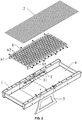
- a nursing bed comprises: a bed frame 1; a net-shaped fabric 2; a spray pipe 3; a heat-insulation and water-draining bottom cover 4; a base 5; an auxiliary load-bearing layer 6.
- the base 5 is in the form of supporting legs, or a bottom of each of the supporting legs is provided with a roller for pushing the nursing bed forward.
- the heat-insulation and water-draining bottom cover 4 is disposed at the lower part of the bed frame 1. At least two edges of the net-shaped fabric 2 are hung between two opposite edges of the bed frame 1 to form a mutual positioning structure. Specifically, the relatively longer edges of the net-shaped fabric 2 are fixed on the bed frame 1 by the hanging structure.
- the auxiliary load-bearing layer 6 is disposed beneath the net-shaped fabric 2.
- a pipe slot 31 is disposed on the bed frame 1 or the auxiliary load-bearing frame 61.
- a spray pipe 3 is disposed between the net-shaped fabric 2 and the auxiliary load-bearing layer 6 in the pipe slot 31; and the spray pipe 3 is hidden inside the pipe slot 31 in an idle state.
- the spray pipe 3 extends out of the pipe slot 31 and swings in a shape of a sector in a horizontal direction, and a swing angle is less than or equal to 170°.
- the spray pipe 3 sprays water to wash a lower surface of the net-shaped fabric 2 and an upper surface of the auxiliary load-bearing layer 6 from different directions.
- the body posture of the patient is required to change. When the patient is turned leftward, the lower surface of the net-shaped fabric 2 and the upper surface of the auxiliary load-bearing layer 6 in the middle region and the right side of the bed are washed. When the patient is turned rightward, the lower surface of the net-shaped fabric 2 and the upper surface of the auxiliary load-bearing layer 6 in the middle region and the left side of the bed are washed.
- the auxiliary load-bearing layer 6 comprises a rigid body 63, an elastic body 64, and a plurality of holes 62.
- An outer side of the elastic body 64 is wrapped with a waterproof and anti-fouling surface layer.
- Each of the holes 62 of the auxiliary load-bearing layer 6 is in the form of an inverted cone structure with a relatively large upper part and a relatively small lower part.
- a diameter of an inscribed circle of the holes 62 is between 5 and 60 mm.
- the elastic body 63 separated by the holes 62 forms a grid supporting surface beneath the net-shaped fabric 2.
- a grid line width D of the grid supporting surface facing the net-shaped fabric is between 0.3 and 3 mm.
- the auxiliary load-bearing layer 6 is disposed inside an auxiliary load-bearing frame 61 and is located at an inner side of the bed frame 1 by the auxiliary load-bearing frame 61.
- the auxiliary load-bearing frame 61 and the bed frame 1 form a spacing-adjustable positioning structure. A distance between the net-shaped fabric 2 and the grid supporting surface exceeds 15 mm in an empty load state.
- an edge of the rigid body 63 of the auxiliary load-bearing layer 6 is provided with a hanging hole.
- the auxiliary load-bearing frame 61 is provided with a hanging column 65.
- the auxiliary load-bearing layer 6 is mounted on the hanging column 65 of the auxiliary load-bearing frame 61 via the hanging hole.
- the hanging column 65 of the auxiliary load-bearing frame 61 is independently adjustable in a vertical direction relative to the auxiliary load-bearing frame 61, and a vertical displacement of the hanging column 65 is less than or equal to 7 cm.
- the auxiliary load-bearing frame 61 and the bed frame 1 form a spacing-adjustable positioning structure, and a maximum vertical displacement of the auxiliary load-bearing frame 61 is less than or equal to 8 cm.
- a distance between the auxiliary load-bearing frame 61 and the net-shaped fabric 2 is adjusted according to personal habit or the requirement from the doctor.
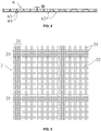
- the net-shaped fabric 2 comprises a warp and a weft 21, and the warp and the weft 21 are interwoven to form mesh openings 22.
- a diameter of the mesh openings 22 or a diameter of an inscribed circle of the mesh openings 22 is between 2 and 6 folds of a diameter of the warp or the weft 21.
- the diameter of the warp or the weft 21 is less than 0.55 mm.
- the diameter of the mesh openings 22 or the diameter of the inscribed circle of the mesh openings 22 is less than 1.5 mm.
- An area of an opening of each mesh opening 22 accounts for between 35% and 78% of a total area of the mesh opening 22.
- a thickness of the net-shaped fabric 2 is less than 1.1 mm.
- Interwoven strips 23 are formed on the net-shaped fabric 2 along the direction of the warp and/or the direction of the weft by congested warps or wefts. Each of the interwoven strips 23 comprises between 2 and 5 warps or wefts 21. The interwoven strips 23 are uniformly distributed on the net-shaped fabric 2 in a comb-like manner or a grid-like manner. A minimum space between two adjacent interwoven strips 23 is 3 mm, and a maximum space between two adjacent interwoven strips 23 is 50 mm. A surface of the interwoven strip 23 comprises grooves filled with waterproof adhesive.
- stainless steel wires 66 are disposed on the auxiliary load-bearing frame 61 in parallel to the long side and short side of the auxiliary load-bearing frame 61, with an arrangement distance of between 5 and 60 mm.
- the stainless steel wires 66 pass through openings of the stop boards 67 to connect to one end of a spring 68, and the other end of the spring 68 is fixed on the auxiliary load-bearing frame 61.
- the stainless steel wires 66 are in sliding fit with the openings of the stop boards 67.
- the spring 68 cannot pass through the openings of the stop boards 67.
- the stainless steel wires 66, the spring 68, and the stop boards 67 combine to form a flexible connection and mutual positioning with the auxiliary load-bearing frame 61.
- the stretch length of the stainless steel wires 66 are negligible.
- the stretch length of the spring 68 is determined by the distance between the stop boards 67 and the auxiliary load-bearing frame 61.
- the stretch value of the spring 68 increases with the increase of the distance between the stop boards 67 and the auxiliary load-bearing frame 61.
- the stainless steel wires 66, the spring 68, and the stop boards 67 combine to form the auxiliary load-bearing layer 6.
Landscapes
- Health & Medical Sciences (AREA)
- Nursing (AREA)
- Life Sciences & Earth Sciences (AREA)
- Animal Behavior & Ethology (AREA)
- General Health & Medical Sciences (AREA)
- Public Health (AREA)
- Veterinary Medicine (AREA)
- Epidemiology (AREA)
- Invalid Beds And Related Equipment (AREA)
Claims (8)
- Pflegebett, umfassend:einen Bettrahmen;ein netzförmiges Gewebe;ein Sprührohr;eine Wärme isolierende und Wasser abführende untere Abdeckung;eine Basis;eine zusätzliche, lasttragende Schicht, wobei die zusätzliche lasttragende Schicht eine Gitterstütze umfasst, die mehrere Löcher aufweist; undeinen zusätzlichen, lasttragenden Rahmen;wobeidie Wärme isolierende und Wasser abführende untere Abdeckung an einem unteren Teil des Bettrahmens angeordnet ist;mindestens zwei Ränder des netzförmigen Gewebes zwischen zwei entgegengesetzten Kanten des Bettrahmens aufgehängt sind, um eine gemeinsame Positionierstruktur zu bilden;die zusätzliche, lasttragende Schicht unter dem netzförmigen Gewebe angeordnet ist;die Gitterstütze eine Gitter tragende Fläche unter dem netzförmigen Gewebe umfasst; wobei eine Gitterlinienbreite der Gitter tragenden Fläche zwischen 0,3 und 3 mm beträgt;ein Durchmesser eines Innenkreises der Löcher zwischen 5 und 60 mm ist;die zusätzliche, lasttragende Schicht im Inneren des zusätzlichen, lasttragenden Rahmens angeordnet ist und auf einer Innenseite des Bettrahmens über den zusätzlichen, lasttragenden Rahmen vorgesehen ist;der zusätzliche, lasttragende Rahmen und der Bettrahmen zusammenwirken, um eine abstandverstellbare Positionierstruktur zu bilden; undein Abstand zwischen dem netzförmigen Gewebe und der Gitterstützfläche in einem leeren Ladezustand 15 mm übersteigt.
- Bett nach Anspruch 1, dadurch gekennzeichnet, dass die zusätzliche, lasttragende Schicht einen starren Körper und einen elastischen Körper umfasst und die mehrere Löcher der zusätzlichen, lasttragenden Schicht die Form eines umgekehrten Kegels mit einem relativ großen oberen Teil und einem relativ kleinen unteren Teil aufweisen.
- Bett nach Anspruch 1 oder 2, dadurch gekennzeichnet, dassein Rand des starren Körpers der zusätzlichen, lasttragenden Schicht mit einem Hängeloch versehen ist;der zusätzliche, lasttragende Rahmen mit einer Hängesäule versehen ist;die zusätzliche, lasttragende Schicht an der Hängesäule des zusätzlichen, lasttragenden Rahmens über das Hängeloch montiert ist; unddie Hängesäule des zusätzlichen, lasttragenden Rahmens in einer vertikalen Richtung in Bezug auf den zusätzlichen, lasttragenden Rahmen unabhängig verstellbar ist, und eine vertikale Verschiebung der Hängesäule weniger als oder gleich 7 cm ist.
- Bett nach Anspruch 1, dadurch gekennzeichnet, dass die Gitterstütze der zusätzlichen, lasttragenden Schicht rostfreie Stahldrähte, die in Länge und Breite gleich beabstandet sind, und Stopp-Bretter umfasst; die rostfreien Stahldrähte durch Öffnungen der Stopp-Bretter gehen, um sich an ein Ende einer Feder anzuschließen, und das andere Ende der Feder an dem zusätzlichen, lasttragenden Rahmen befestigt ist; ein Abstand zwischen den Stopp-Brettern und dem zusätzlichen, lasttragenden Rahmen verstellbar ist, und die Stopp-Bretter und der zusätzliche, lasttragende Rahmen in einer vorgegebenen Position fixiert werden können.
- Bett nach Anspruch 1, 2 oder 4, dadurch gekennzeichnet, dass eine maximale, vertikale Verschiebung des zusätzlichen, lasttragenden Rahmens weniger oder gleich 8 cm ist.
- Bett nach Anspruch 1, dadurch gekennzeichnet, dass das netzförmige Gewebe eine Kette und einen Schuss umfasst, und die Kette und der Schuss verflochten sind, um Maschenöffnungen zu bilden; ein Durchmesser der Maschenöffnungen oder ein Durchmesser eines Innenkreises der Maschenöffnungen das 2- bis 6-fache eines Durchmessers der Kette oder des Schusses ist; der Durchmesser der Kette oder des Schusses kleiner als 0,55 mm ist; der Durchmesser der Maschenöffnungen oder der Durchmesser des Innenkreises der Maschenöffnungen kleiner als 1,5 mm ist; die Fläche einer Öffnung von jeder Maschenöffnung zwischen 35 % und 78 % einer Gesamtfläche der Maschenöffnung ausmacht; die Dicke des netzförmigen Gewebes weniger als 1,1 mm ist; mindestens zwei Ränder des netzförmigen Gewebes zwischen zwei entgegengesetzten Kanten des Bettrahmens hängen, um die gemeinsame Positionierstruktur zu bilden.
- Bett nach Anspruch 1 oder 6, dadurch gekennzeichnet, dassverflochtene Streifen auf dem netzförmigen Gewebe entlang einer Kettenrichtung und bzw. oder einer Schussrichtung durch geballte Ketten- oder Schussfäden gebildet werden;jeder verflochtene Streifen zwischen 2 und 5 Ketten oder Schüsse umfasst;die verflochtenen Streifen gleichmäßig auf dem netzförmigen Gewebe auf eine wabenförmige oder eine gitterförmige Weise verteilt sind;ein Mindestraum zwischen zwei benachbarten, verflochtenen Streifen 3 mm ist und ein Höchstraum zwischen zwei benachbarten, verflochtenen Streifen 50 mm ist; undeine Oberfläche des verflochtenen Streifens Rillen umfasst, die mit einem wasserfesten Klebstoff gefüllt sind.
- Bett nach Anspruch 1, dadurch gekennzeichnet, dassein Rohrschlitz am Bettrahmen oder dem zusätzlichen, lasttragenden Rahmen angeordnet ist;das Sprührohr zwischen dem netzförmigen Gewebe und der zusätzlichen, lasttragenden Schicht und im Rohrschlitz angeordnet ist; unddas Sprührohr im Inneren des Rohrschlitzes in einem Ruhezustand verborgen ist.
Applications Claiming Priority (2)
| Application Number | Priority Date | Filing Date | Title |
|---|---|---|---|
| CN201310628493.9A CN103598956B (zh) | 2013-11-29 | 2013-11-29 | 网式保温护理床 |
| PCT/CN2014/092442 WO2015078401A1 (zh) | 2013-11-29 | 2014-11-28 | 网式保温护理床 |
Publications (3)
| Publication Number | Publication Date |
|---|---|
| EP3075366A1 EP3075366A1 (de) | 2016-10-05 |
| EP3075366A4 EP3075366A4 (de) | 2016-11-30 |
| EP3075366B1 true EP3075366B1 (de) | 2017-07-19 |
Family
ID=50117267
Family Applications (1)
| Application Number | Title | Priority Date | Filing Date |
|---|---|---|---|
| EP14865235.7A Active EP3075366B1 (de) | 2013-11-29 | 2014-11-28 | Netzartiges wärmedämmungspflegebett |
Country Status (6)
| Country | Link |
|---|---|
| US (1) | US10383781B2 (de) |
| EP (1) | EP3075366B1 (de) |
| JP (1) | JP6427188B2 (de) |
| CN (1) | CN103598956B (de) |
| ES (1) | ES2642733T3 (de) |
| WO (1) | WO2015078401A1 (de) |
Families Citing this family (5)
| Publication number | Priority date | Publication date | Assignee | Title |
|---|---|---|---|---|
| CN103598956B (zh) * | 2013-11-29 | 2016-06-22 | 王厦定 | 网式保温护理床 |
| US10441084B2 (en) * | 2017-02-18 | 2019-10-15 | Ulife Healthcare Inc. | Lightweight modular bed |
| TWM540570U (zh) * | 2017-02-18 | 2017-05-01 | Ulife Healthcare Inc | 輕量化床架裝置 |
| CN110584381A (zh) * | 2019-09-19 | 2019-12-20 | 杨松 | 可拆卸床 |
| WO2022272265A1 (en) * | 2021-06-22 | 2022-12-29 | Aludra Lynnd | Multilayered, adjustable mattress system with orbital springs |
Family Cites Families (31)
| Publication number | Priority date | Publication date | Assignee | Title |
|---|---|---|---|---|
| US3701170A (en) * | 1971-07-08 | 1972-10-31 | James M Bond | Apparatus facilitating care of a bedfast patient |
| US3905055A (en) * | 1974-08-09 | 1975-09-16 | Reed F Blair Inc | Patient lift and support for hospital bed |
| US4052243A (en) * | 1975-01-28 | 1977-10-04 | Polymer Processing Research Institute Ltd. | Method for producing a cross-laminated cloth-like product from wide warp and weft webs |
| JPS5938934Y2 (ja) * | 1979-02-26 | 1984-10-30 | アキレス株式会社 | ベツトポトム |
| JPS59124526U (ja) * | 1983-02-14 | 1984-08-22 | 内田 泰夫 | 夜尿対策用寝具 |
| JPH0346750Y2 (de) * | 1987-03-25 | 1991-10-03 | ||
| RU2128479C1 (ru) * | 1988-03-23 | 1999-04-10 | Хилл-Ром, Инк. | Устройство для поддержания пациента (варианты) и способ поддержания тела человека на матраце |
| JPH02104356A (ja) * | 1988-10-13 | 1990-04-17 | Tsuneo Yamamoto | 寝たきり病人用などの自動身辺介護装置 |
| JPH02126629U (de) * | 1989-03-28 | 1990-10-18 | ||
| US5355540A (en) * | 1993-10-12 | 1994-10-18 | Allen James O | Invalid bed |
| JP2726875B2 (ja) * | 1995-03-08 | 1998-03-11 | 有限会社メディカル加藤 | ストレッチャ |
| US5598592A (en) * | 1995-11-13 | 1997-02-04 | North America Rescue Products | Easily decontaminated stretcher |
| US5878452A (en) * | 1996-12-03 | 1999-03-09 | Hill-Rom, Inc. | Long term care bed controls |
| JP3043953U (ja) * | 1997-05-30 | 1997-12-12 | 毅 福崎 | 床ずれ防止ベッド |
| CN2478473Y (zh) * | 2001-05-15 | 2002-02-27 | 祝惠松 | 一种有刚性框架的弹性床垫 |
| US8615832B2 (en) * | 2009-12-09 | 2013-12-31 | Xiading Wang | Nursing bed |
| US9375375B2 (en) * | 2003-08-16 | 2016-06-28 | Xiading Wang | Nursing bed |
| CN2662872Y (zh) * | 2003-08-16 | 2004-12-15 | 王厦定 | 卫生护理床 |
| CN101940517B (zh) * | 2010-08-04 | 2017-04-05 | 王厦定 | 卫生护理网式床 |
| CN201005890Y (zh) * | 2006-09-19 | 2008-01-16 | 王厦定 | 保温式卫生护理床 |
| CN100562303C (zh) * | 2006-09-19 | 2009-11-25 | 王厦定 | 保温式卫生护理床 |
| US8914924B2 (en) * | 2007-04-13 | 2014-12-23 | Stryker Corporation | Patient support with universal energy supply system |
| JP2009045151A (ja) * | 2007-08-16 | 2009-03-05 | Shigadry With Earth:Kk | 介護用ベッド装置 |
| JP2010017246A (ja) * | 2008-07-08 | 2010-01-28 | Kazuyoshi Iida | 介護用ベッド装置 |
| US20100313357A1 (en) * | 2009-06-12 | 2010-12-16 | Wen-Lung Chang | Medical Bed Structure |
| US8935821B2 (en) * | 2009-09-21 | 2015-01-20 | Phoenix Design, Llc | Structure for suspended bedding |
| EP2571473B1 (de) * | 2010-05-17 | 2014-12-10 | King Saud University | Bewegliche Badewanne und Hebevorrichtug zum Baden von Intensivpatienten |
| CN201996755U (zh) * | 2011-03-03 | 2011-10-05 | 王力军 | 一种长期卧床病人护理床 |
| CN202982464U (zh) * | 2012-12-04 | 2013-06-12 | 陈君华 | 护理床框架式悬浮装置及浴盆 |
| CN203576781U (zh) * | 2013-11-29 | 2014-05-07 | 王厦定 | 网式保温护理床 |
| CN103598956B (zh) * | 2013-11-29 | 2016-06-22 | 王厦定 | 网式保温护理床 |
-
2013
- 2013-11-29 CN CN201310628493.9A patent/CN103598956B/zh active Active
-
2014
- 2014-11-28 EP EP14865235.7A patent/EP3075366B1/de active Active
- 2014-11-28 ES ES14865235.7T patent/ES2642733T3/es active Active
- 2014-11-28 JP JP2016532617A patent/JP6427188B2/ja active Active
- 2014-11-28 WO PCT/CN2014/092442 patent/WO2015078401A1/zh not_active Ceased
-
2016
- 2016-05-26 US US15/166,234 patent/US10383781B2/en active Active
Non-Patent Citations (1)
| Title |
|---|
| None * |
Also Published As
| Publication number | Publication date |
|---|---|
| CN103598956B (zh) | 2016-06-22 |
| JP2016539691A (ja) | 2016-12-22 |
| EP3075366A1 (de) | 2016-10-05 |
| JP6427188B2 (ja) | 2018-11-21 |
| US20160270992A1 (en) | 2016-09-22 |
| WO2015078401A1 (zh) | 2015-06-04 |
| ES2642733T3 (es) | 2017-11-17 |
| US10383781B2 (en) | 2019-08-20 |
| EP3075366A4 (de) | 2016-11-30 |
| CN103598956A (zh) | 2014-02-26 |
Similar Documents
| Publication | Publication Date | Title |
|---|---|---|
| EP3075366B1 (de) | Netzartiges wärmedämmungspflegebett | |
| JP2015521866A5 (de) | ||
| RU2015155838A (ru) | Гигиеническая прокладка | |
| US20160192617A1 (en) | Vapor Proof Dual Cover System for Pet Beds with Pressure Relief Zones | |
| US20080045872A1 (en) | Elastic Bandage with Electrodes Spaced Apart From One Another | |
| US11389352B2 (en) | Devices and methods to help prevent decubitus ulcers | |
| JP2019535468A5 (de) | ||
| US20160095776A1 (en) | Leg Support Device | |
| WO2021071370A1 (en) | Mattress with ventilation system for the prevention and the treatment of decubitus ulcers or bedsores on immobile patients | |
| JP2004008466A (ja) | 起伏機能を有するベッド等における転落防止装置 | |
| CN205913485U (zh) | 一种充气床垫 | |
| EP1874252A1 (de) | Vorrichtung zur verhinderung von dekubitus | |
| CN203576781U (zh) | 网式保温护理床 | |
| CN209769019U (zh) | 一种航天员在轨使用的防护软鞋 | |
| US20160081867A1 (en) | Modular therapy mattress | |
| CN204048155U (zh) | 一种带有喷气气囊的防褥疮便捷式病裤 | |
| CN204744747U (zh) | 一种床上起身辅助装置 | |
| RU80103U1 (ru) | Коврик для дезинфекции (варианты) | |
| CN111683570A (zh) | 床垫 | |
| KR102243429B1 (ko) | 매트리스 장치 | |
| JP2019188048A (ja) | マットレスユニット及び制御装置 | |
| CN201894711U (zh) | 卫生护理网式床 | |
| CN201404336Y (zh) | 隔尿垫 | |
| JP3043953U (ja) | 床ずれ防止ベッド | |
| KR102892951B1 (ko) | 인체감지수단이 구비되는 전기온열보료 |
Legal Events
| Date | Code | Title | Description |
|---|---|---|---|
| PUAI | Public reference made under article 153(3) epc to a published international application that has entered the european phase |
Free format text: ORIGINAL CODE: 0009012 |
|
| 17P | Request for examination filed |
Effective date: 20160615 |
|
| AK | Designated contracting states |
Kind code of ref document: A1 Designated state(s): AL AT BE BG CH CY CZ DE DK EE ES FI FR GB GR HR HU IE IS IT LI LT LU LV MC MK MT NL NO PL PT RO RS SE SI SK SM TR |
|
| AX | Request for extension of the european patent |
Extension state: BA ME |
|
| A4 | Supplementary search report drawn up and despatched |
Effective date: 20161027 |
|
| RIC1 | Information provided on ipc code assigned before grant |
Ipc: A61G 7/00 20060101AFI20161021BHEP Ipc: A61G 7/057 20060101ALI20161021BHEP Ipc: A61G 7/05 20060101ALI20161021BHEP Ipc: A61G 7/047 20060101ALI20161021BHEP |
|
| GRAP | Despatch of communication of intention to grant a patent |
Free format text: ORIGINAL CODE: EPIDOSNIGR1 |
|
| DAX | Request for extension of the european patent (deleted) | ||
| INTG | Intention to grant announced |
Effective date: 20170207 |
|
| GRAS | Grant fee paid |
Free format text: ORIGINAL CODE: EPIDOSNIGR3 |
|
| GRAA | (expected) grant |
Free format text: ORIGINAL CODE: 0009210 |
|
| RAP1 | Party data changed (applicant data changed or rights of an application transferred) |
Owner name: WANG, XIADING |
|
| RIN1 | Information on inventor provided before grant (corrected) |
Inventor name: WANG, XIADING |
|
| AK | Designated contracting states |
Kind code of ref document: B1 Designated state(s): AL AT BE BG CH CY CZ DE DK EE ES FI FR GB GR HR HU IE IS IT LI LT LU LV MC MK MT NL NO PL PT RO RS SE SI SK SM TR |
|
| REG | Reference to a national code |
Ref country code: GB Ref legal event code: FG4D |
|
| REG | Reference to a national code |
Ref country code: CH Ref legal event code: EP |
|
| REG | Reference to a national code |
Ref country code: IE Ref legal event code: FG4D |
|
| REG | Reference to a national code |
Ref country code: AT Ref legal event code: REF Ref document number: 909671 Country of ref document: AT Kind code of ref document: T Effective date: 20170815 |
|
| REG | Reference to a national code |
Ref country code: DE Ref legal event code: R096 Ref document number: 602014012140 Country of ref document: DE |
|
| REG | Reference to a national code |
Ref country code: FR Ref legal event code: PLFP Year of fee payment: 4 |
|
| REG | Reference to a national code |
Ref country code: ES Ref legal event code: FG2A Ref document number: 2642733 Country of ref document: ES Kind code of ref document: T3 Effective date: 20171117 |
|
| REG | Reference to a national code |
Ref country code: NL Ref legal event code: MP Effective date: 20170719 |
|
| REG | Reference to a national code |
Ref country code: LT Ref legal event code: MG4D |
|
| REG | Reference to a national code |
Ref country code: AT Ref legal event code: MK05 Ref document number: 909671 Country of ref document: AT Kind code of ref document: T Effective date: 20170719 |
|
| PG25 | Lapsed in a contracting state [announced via postgrant information from national office to epo] |
Ref country code: HR Free format text: LAPSE BECAUSE OF FAILURE TO SUBMIT A TRANSLATION OF THE DESCRIPTION OR TO PAY THE FEE WITHIN THE PRESCRIBED TIME-LIMIT Effective date: 20170719 Ref country code: LT Free format text: LAPSE BECAUSE OF FAILURE TO SUBMIT A TRANSLATION OF THE DESCRIPTION OR TO PAY THE FEE WITHIN THE PRESCRIBED TIME-LIMIT Effective date: 20170719 Ref country code: NO Free format text: LAPSE BECAUSE OF FAILURE TO SUBMIT A TRANSLATION OF THE DESCRIPTION OR TO PAY THE FEE WITHIN THE PRESCRIBED TIME-LIMIT Effective date: 20171019 Ref country code: FI Free format text: LAPSE BECAUSE OF FAILURE TO SUBMIT A TRANSLATION OF THE DESCRIPTION OR TO PAY THE FEE WITHIN THE PRESCRIBED TIME-LIMIT Effective date: 20170719 Ref country code: NL Free format text: LAPSE BECAUSE OF FAILURE TO SUBMIT A TRANSLATION OF THE DESCRIPTION OR TO PAY THE FEE WITHIN THE PRESCRIBED TIME-LIMIT Effective date: 20170719 Ref country code: AT Free format text: LAPSE BECAUSE OF FAILURE TO SUBMIT A TRANSLATION OF THE DESCRIPTION OR TO PAY THE FEE WITHIN THE PRESCRIBED TIME-LIMIT Effective date: 20170719 Ref country code: SE Free format text: LAPSE BECAUSE OF FAILURE TO SUBMIT A TRANSLATION OF THE DESCRIPTION OR TO PAY THE FEE WITHIN THE PRESCRIBED TIME-LIMIT Effective date: 20170719 |
|
| PG25 | Lapsed in a contracting state [announced via postgrant information from national office to epo] |
Ref country code: BG Free format text: LAPSE BECAUSE OF FAILURE TO SUBMIT A TRANSLATION OF THE DESCRIPTION OR TO PAY THE FEE WITHIN THE PRESCRIBED TIME-LIMIT Effective date: 20171019 Ref country code: PL Free format text: LAPSE BECAUSE OF FAILURE TO SUBMIT A TRANSLATION OF THE DESCRIPTION OR TO PAY THE FEE WITHIN THE PRESCRIBED TIME-LIMIT Effective date: 20170719 Ref country code: GR Free format text: LAPSE BECAUSE OF FAILURE TO SUBMIT A TRANSLATION OF THE DESCRIPTION OR TO PAY THE FEE WITHIN THE PRESCRIBED TIME-LIMIT Effective date: 20171020 Ref country code: RS Free format text: LAPSE BECAUSE OF FAILURE TO SUBMIT A TRANSLATION OF THE DESCRIPTION OR TO PAY THE FEE WITHIN THE PRESCRIBED TIME-LIMIT Effective date: 20170719 Ref country code: IS Free format text: LAPSE BECAUSE OF FAILURE TO SUBMIT A TRANSLATION OF THE DESCRIPTION OR TO PAY THE FEE WITHIN THE PRESCRIBED TIME-LIMIT Effective date: 20171119 Ref country code: LV Free format text: LAPSE BECAUSE OF FAILURE TO SUBMIT A TRANSLATION OF THE DESCRIPTION OR TO PAY THE FEE WITHIN THE PRESCRIBED TIME-LIMIT Effective date: 20170719 |
|
| REG | Reference to a national code |
Ref country code: DE Ref legal event code: R097 Ref document number: 602014012140 Country of ref document: DE |
|
| PG25 | Lapsed in a contracting state [announced via postgrant information from national office to epo] |
Ref country code: DK Free format text: LAPSE BECAUSE OF FAILURE TO SUBMIT A TRANSLATION OF THE DESCRIPTION OR TO PAY THE FEE WITHIN THE PRESCRIBED TIME-LIMIT Effective date: 20170719 Ref country code: CZ Free format text: LAPSE BECAUSE OF FAILURE TO SUBMIT A TRANSLATION OF THE DESCRIPTION OR TO PAY THE FEE WITHIN THE PRESCRIBED TIME-LIMIT Effective date: 20170719 Ref country code: RO Free format text: LAPSE BECAUSE OF FAILURE TO SUBMIT A TRANSLATION OF THE DESCRIPTION OR TO PAY THE FEE WITHIN THE PRESCRIBED TIME-LIMIT Effective date: 20170719 |
|
| PLBE | No opposition filed within time limit |
Free format text: ORIGINAL CODE: 0009261 |
|
| STAA | Information on the status of an ep patent application or granted ep patent |
Free format text: STATUS: NO OPPOSITION FILED WITHIN TIME LIMIT |
|
| PG25 | Lapsed in a contracting state [announced via postgrant information from national office to epo] |
Ref country code: SM Free format text: LAPSE BECAUSE OF FAILURE TO SUBMIT A TRANSLATION OF THE DESCRIPTION OR TO PAY THE FEE WITHIN THE PRESCRIBED TIME-LIMIT Effective date: 20170719 Ref country code: SK Free format text: LAPSE BECAUSE OF FAILURE TO SUBMIT A TRANSLATION OF THE DESCRIPTION OR TO PAY THE FEE WITHIN THE PRESCRIBED TIME-LIMIT Effective date: 20170719 Ref country code: EE Free format text: LAPSE BECAUSE OF FAILURE TO SUBMIT A TRANSLATION OF THE DESCRIPTION OR TO PAY THE FEE WITHIN THE PRESCRIBED TIME-LIMIT Effective date: 20170719 |
|
| PGFP | Annual fee paid to national office [announced via postgrant information from national office to epo] |
Ref country code: IE Payment date: 20180226 Year of fee payment: 4 |
|
| 26N | No opposition filed |
Effective date: 20180420 |
|
| PG25 | Lapsed in a contracting state [announced via postgrant information from national office to epo] |
Ref country code: MC Free format text: LAPSE BECAUSE OF FAILURE TO SUBMIT A TRANSLATION OF THE DESCRIPTION OR TO PAY THE FEE WITHIN THE PRESCRIBED TIME-LIMIT Effective date: 20170719 |
|
| PG25 | Lapsed in a contracting state [announced via postgrant information from national office to epo] |
Ref country code: LI Free format text: LAPSE BECAUSE OF NON-PAYMENT OF DUE FEES Effective date: 20171130 Ref country code: CH Free format text: LAPSE BECAUSE OF NON-PAYMENT OF DUE FEES Effective date: 20171130 |
|
| PG25 | Lapsed in a contracting state [announced via postgrant information from national office to epo] |
Ref country code: LU Free format text: LAPSE BECAUSE OF NON-PAYMENT OF DUE FEES Effective date: 20171128 Ref country code: SI Free format text: LAPSE BECAUSE OF FAILURE TO SUBMIT A TRANSLATION OF THE DESCRIPTION OR TO PAY THE FEE WITHIN THE PRESCRIBED TIME-LIMIT Effective date: 20170719 |
|
| REG | Reference to a national code |
Ref country code: BE Ref legal event code: MM Effective date: 20171130 |
|
| PG25 | Lapsed in a contracting state [announced via postgrant information from national office to epo] |
Ref country code: MT Free format text: LAPSE BECAUSE OF NON-PAYMENT OF DUE FEES Effective date: 20171128 |
|
| PG25 | Lapsed in a contracting state [announced via postgrant information from national office to epo] |
Ref country code: BE Free format text: LAPSE BECAUSE OF NON-PAYMENT OF DUE FEES Effective date: 20171130 |
|
| PG25 | Lapsed in a contracting state [announced via postgrant information from national office to epo] |
Ref country code: HU Free format text: LAPSE BECAUSE OF FAILURE TO SUBMIT A TRANSLATION OF THE DESCRIPTION OR TO PAY THE FEE WITHIN THE PRESCRIBED TIME-LIMIT; INVALID AB INITIO Effective date: 20141128 |
|
| REG | Reference to a national code |
Ref country code: IE Ref legal event code: MM4A |
|
| PG25 | Lapsed in a contracting state [announced via postgrant information from national office to epo] |
Ref country code: IE Free format text: LAPSE BECAUSE OF NON-PAYMENT OF DUE FEES Effective date: 20181128 Ref country code: CY Free format text: LAPSE BECAUSE OF FAILURE TO SUBMIT A TRANSLATION OF THE DESCRIPTION OR TO PAY THE FEE WITHIN THE PRESCRIBED TIME-LIMIT Effective date: 20170719 |
|
| PG25 | Lapsed in a contracting state [announced via postgrant information from national office to epo] |
Ref country code: MK Free format text: LAPSE BECAUSE OF FAILURE TO SUBMIT A TRANSLATION OF THE DESCRIPTION OR TO PAY THE FEE WITHIN THE PRESCRIBED TIME-LIMIT Effective date: 20170719 |
|
| PG25 | Lapsed in a contracting state [announced via postgrant information from national office to epo] |
Ref country code: TR Free format text: LAPSE BECAUSE OF FAILURE TO SUBMIT A TRANSLATION OF THE DESCRIPTION OR TO PAY THE FEE WITHIN THE PRESCRIBED TIME-LIMIT Effective date: 20170719 |
|
| PG25 | Lapsed in a contracting state [announced via postgrant information from national office to epo] |
Ref country code: PT Free format text: LAPSE BECAUSE OF FAILURE TO SUBMIT A TRANSLATION OF THE DESCRIPTION OR TO PAY THE FEE WITHIN THE PRESCRIBED TIME-LIMIT Effective date: 20170719 |
|
| PG25 | Lapsed in a contracting state [announced via postgrant information from national office to epo] |
Ref country code: AL Free format text: LAPSE BECAUSE OF FAILURE TO SUBMIT A TRANSLATION OF THE DESCRIPTION OR TO PAY THE FEE WITHIN THE PRESCRIBED TIME-LIMIT Effective date: 20170719 |
|
| PG25 | Lapsed in a contracting state [announced via postgrant information from national office to epo] |
Ref country code: FR Free format text: LAPSE BECAUSE OF NON-PAYMENT OF DUE FEES Effective date: 20211130 |
|
| PG25 | Lapsed in a contracting state [announced via postgrant information from national office to epo] |
Ref country code: IT Free format text: LAPSE BECAUSE OF NON-PAYMENT OF DUE FEES Effective date: 20211128 |
|
| PG25 | Lapsed in a contracting state [announced via postgrant information from national office to epo] |
Ref country code: FR Free format text: LAPSE BECAUSE OF NON-PAYMENT OF DUE FEES Effective date: 20211130 |
|
| PGRI | Patent reinstated in contracting state [announced from national office to epo] |
Ref country code: FR Effective date: 20230622 |
|
| PG25 | Lapsed in a contracting state [announced via postgrant information from national office to epo] |
Ref country code: IT Free format text: LAPSE BECAUSE OF NON-PAYMENT OF DUE FEES Effective date: 20211128 |
|
| PGRI | Patent reinstated in contracting state [announced from national office to epo] |
Ref country code: IT Effective date: 20211130 |
|
| PGFP | Annual fee paid to national office [announced via postgrant information from national office to epo] |
Ref country code: DE Payment date: 20241125 Year of fee payment: 11 |
|
| PGFP | Annual fee paid to national office [announced via postgrant information from national office to epo] |
Ref country code: GB Payment date: 20241119 Year of fee payment: 11 |
|
| PGFP | Annual fee paid to national office [announced via postgrant information from national office to epo] |
Ref country code: FR Payment date: 20241128 Year of fee payment: 11 |
|
| PGFP | Annual fee paid to national office [announced via postgrant information from national office to epo] |
Ref country code: IT Payment date: 20241125 Year of fee payment: 11 Ref country code: ES Payment date: 20241203 Year of fee payment: 11 |