EP3073548B1 - Battery pack - Google Patents
Battery pack Download PDFInfo
- Publication number
- EP3073548B1 EP3073548B1 EP16717531.4A EP16717531A EP3073548B1 EP 3073548 B1 EP3073548 B1 EP 3073548B1 EP 16717531 A EP16717531 A EP 16717531A EP 3073548 B1 EP3073548 B1 EP 3073548B1
- Authority
- EP
- European Patent Office
- Prior art keywords
- battery
- electrode terminal
- battery cell
- battery pack
- fuse
- Prior art date
- Legal status (The legal status is an assumption and is not a legal conclusion. Google has not performed a legal analysis and makes no representation as to the accuracy of the status listed.)
- Active
Links
Images


Classifications
-
- H—ELECTRICITY
- H01—ELECTRIC ELEMENTS
- H01M—PROCESSES OR MEANS, e.g. BATTERIES, FOR THE DIRECT CONVERSION OF CHEMICAL ENERGY INTO ELECTRICAL ENERGY
- H01M50/00—Constructional details or processes of manufacture of the non-active parts of electrochemical cells other than fuel cells, e.g. hybrid cells
- H01M50/50—Current conducting connections for cells or batteries
- H01M50/572—Means for preventing undesired use or discharge
- H01M50/574—Devices or arrangements for the interruption of current
- H01M50/578—Devices or arrangements for the interruption of current in response to pressure
-
- H—ELECTRICITY
- H01—ELECTRIC ELEMENTS
- H01M—PROCESSES OR MEANS, e.g. BATTERIES, FOR THE DIRECT CONVERSION OF CHEMICAL ENERGY INTO ELECTRICAL ENERGY
- H01M50/00—Constructional details or processes of manufacture of the non-active parts of electrochemical cells other than fuel cells, e.g. hybrid cells
- H01M50/20—Mountings; Secondary casings or frames; Racks, modules or packs; Suspension devices; Shock absorbers; Transport or carrying devices; Holders
- H01M50/233—Mountings; Secondary casings or frames; Racks, modules or packs; Suspension devices; Shock absorbers; Transport or carrying devices; Holders characterised by physical properties of casings or racks, e.g. dimensions
- H01M50/24—Mountings; Secondary casings or frames; Racks, modules or packs; Suspension devices; Shock absorbers; Transport or carrying devices; Holders characterised by physical properties of casings or racks, e.g. dimensions adapted for protecting batteries from their environment, e.g. from corrosion
-
- H—ELECTRICITY
- H01—ELECTRIC ELEMENTS
- H01M—PROCESSES OR MEANS, e.g. BATTERIES, FOR THE DIRECT CONVERSION OF CHEMICAL ENERGY INTO ELECTRICAL ENERGY
- H01M50/00—Constructional details or processes of manufacture of the non-active parts of electrochemical cells other than fuel cells, e.g. hybrid cells
- H01M50/20—Mountings; Secondary casings or frames; Racks, modules or packs; Suspension devices; Shock absorbers; Transport or carrying devices; Holders
- H01M50/204—Racks, modules or packs for multiple batteries or multiple cells
- H01M50/207—Racks, modules or packs for multiple batteries or multiple cells characterised by their shape
- H01M50/211—Racks, modules or packs for multiple batteries or multiple cells characterised by their shape adapted for pouch cells
-
- H—ELECTRICITY
- H01—ELECTRIC ELEMENTS
- H01M—PROCESSES OR MEANS, e.g. BATTERIES, FOR THE DIRECT CONVERSION OF CHEMICAL ENERGY INTO ELECTRICAL ENERGY
- H01M50/00—Constructional details or processes of manufacture of the non-active parts of electrochemical cells other than fuel cells, e.g. hybrid cells
- H01M50/20—Mountings; Secondary casings or frames; Racks, modules or packs; Suspension devices; Shock absorbers; Transport or carrying devices; Holders
- H01M50/269—Mechanical means for varying the arrangement of batteries or cells for different uses, e.g. for changing the number of batteries or for switching between series and parallel wiring
-
- H—ELECTRICITY
- H01—ELECTRIC ELEMENTS
- H01M—PROCESSES OR MEANS, e.g. BATTERIES, FOR THE DIRECT CONVERSION OF CHEMICAL ENERGY INTO ELECTRICAL ENERGY
- H01M50/00—Constructional details or processes of manufacture of the non-active parts of electrochemical cells other than fuel cells, e.g. hybrid cells
- H01M50/50—Current conducting connections for cells or batteries
- H01M50/502—Interconnectors for connecting terminals of adjacent batteries; Interconnectors for connecting cells outside a battery casing
- H01M50/503—Interconnectors for connecting terminals of adjacent batteries; Interconnectors for connecting cells outside a battery casing characterised by the shape of the interconnectors
-
- H—ELECTRICITY
- H01—ELECTRIC ELEMENTS
- H01M—PROCESSES OR MEANS, e.g. BATTERIES, FOR THE DIRECT CONVERSION OF CHEMICAL ENERGY INTO ELECTRICAL ENERGY
- H01M50/00—Constructional details or processes of manufacture of the non-active parts of electrochemical cells other than fuel cells, e.g. hybrid cells
- H01M50/50—Current conducting connections for cells or batteries
- H01M50/502—Interconnectors for connecting terminals of adjacent batteries; Interconnectors for connecting cells outside a battery casing
- H01M50/509—Interconnectors for connecting terminals of adjacent batteries; Interconnectors for connecting cells outside a battery casing characterised by the type of connection, e.g. mixed connections
- H01M50/51—Connection only in series
-
- H—ELECTRICITY
- H01—ELECTRIC ELEMENTS
- H01M—PROCESSES OR MEANS, e.g. BATTERIES, FOR THE DIRECT CONVERSION OF CHEMICAL ENERGY INTO ELECTRICAL ENERGY
- H01M50/00—Constructional details or processes of manufacture of the non-active parts of electrochemical cells other than fuel cells, e.g. hybrid cells
- H01M50/50—Current conducting connections for cells or batteries
- H01M50/572—Means for preventing undesired use or discharge
- H01M50/574—Devices or arrangements for the interruption of current
- H01M50/579—Devices or arrangements for the interruption of current in response to shock
-
- H—ELECTRICITY
- H01—ELECTRIC ELEMENTS
- H01M—PROCESSES OR MEANS, e.g. BATTERIES, FOR THE DIRECT CONVERSION OF CHEMICAL ENERGY INTO ELECTRICAL ENERGY
- H01M50/00—Constructional details or processes of manufacture of the non-active parts of electrochemical cells other than fuel cells, e.g. hybrid cells
- H01M50/50—Current conducting connections for cells or batteries
- H01M50/572—Means for preventing undesired use or discharge
- H01M50/574—Devices or arrangements for the interruption of current
- H01M50/581—Devices or arrangements for the interruption of current in response to temperature
-
- H—ELECTRICITY
- H01—ELECTRIC ELEMENTS
- H01M—PROCESSES OR MEANS, e.g. BATTERIES, FOR THE DIRECT CONVERSION OF CHEMICAL ENERGY INTO ELECTRICAL ENERGY
- H01M2200/00—Safety devices for primary or secondary batteries
- H01M2200/10—Temperature sensitive devices
- H01M2200/103—Fuse
-
- Y—GENERAL TAGGING OF NEW TECHNOLOGICAL DEVELOPMENTS; GENERAL TAGGING OF CROSS-SECTIONAL TECHNOLOGIES SPANNING OVER SEVERAL SECTIONS OF THE IPC; TECHNICAL SUBJECTS COVERED BY FORMER USPC CROSS-REFERENCE ART COLLECTIONS [XRACs] AND DIGESTS
- Y02—TECHNOLOGIES OR APPLICATIONS FOR MITIGATION OR ADAPTATION AGAINST CLIMATE CHANGE
- Y02E—REDUCTION OF GREENHOUSE GAS [GHG] EMISSIONS, RELATED TO ENERGY GENERATION, TRANSMISSION OR DISTRIBUTION
- Y02E60/00—Enabling technologies; Technologies with a potential or indirect contribution to GHG emissions mitigation
- Y02E60/10—Energy storage using batteries
Definitions
- the present invention relates to a battery pack, and more particularly, to a battery pack including a switching device for preventing a short circuit from occurring.
- rechargeable batteries may be chargeable and dischargeable batteries, unlike primary batteries that are impossible to charge.
- Such rechargeable batteries include low-capacity battery packs that are used for portable small electronic devices and high-capacity battery packs that are used for power sources for driving motors of hybrid vehicles.
- the battery pack according to the related art includes a battery module in which a plurality of battery cells are connected in series or parallel and a battery case in which the battery module is built, as disclosed in EP 2 631 968 A2 .
- the battery pack according to the related art may cause a safety issue when the battery pack is pressed by a heavy object, or a strong impact is applied to the battery pack. That is, when a nail passes penetrates the battery pack, or compression force or an impact is applied to the battery pack, a positive electrode and a negative electrode of the battery cell are connected to each other to cause the short circuit. As a result, the battery cell may be ignited or exploded by an exothermic reaction due to the short circuit.
- EP 2 631 968 A2 discloses in this context an external short induction kit connected to the battery module.
- EP 2 741 348 A1 discloses a battery pack including a fuse connected in a circuit between battery modules, and a circuit breaker connected to the circuit to break the fuse when conduction is performed due to swelling of the battery cells.
- an object of the present invention is to provide a battery pack in which battery cells connected to each other in series or parallel are prevented from being connected to each other when an impact is transmitted to prevent a short circuit from occurring by an exothermic reaction, thereby preventing the battery cell from being ignited or exploded.
- the first fuse When the first and second switches contact each other, the first fuse may be melted and disconnected by overcurrent or heat that is generated by connection between the second electrode terminal of the first battery cell and the second electrode terminal of the second battery cell to block the connection between the first battery cell and the second battery cell.
- the second fuse When the second switch and the third switch contact each other, the second fuse may be melted and disconnected by overcurrent or heat that is generated by connection between the second electrode terminal of the second battery cell and the first electrode terminal of the third battery cell to block the connection between the second battery cell and the third battery cell.
- Each of the switches may include a metal plate having conductivity.
- the switches may be maintained to be spaced apart from each other.
- the switches may be disposed above an entire outer circumferential surface of the battery module.
- the battery module may further include a fourth battery cell disposed below the third battery cell, and the fuse part may further include a fourth fuse connecting the third and fourth battery cells to each other in series.
- the first electrode terminal may include a positive electrode terminal
- the second electrode terminal may include a negative electrode terminal.
- a buffer space may be defined between the switching device and the battery module.
- a buffer member may be provided in the buffer space.
- the present invention has effects as follows.
- a battery pack according to the present invention includes a switching device for detecting an external impact.
- the switching device may detect an impact transmitted to the battery pack to block connection between the battery cells provided in the battery pack to prevent the battery cells from being short-circuited by an exothermic reaction, thereby solving the limitation in safety such as ignition and explosion.
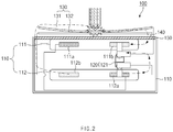
- a battery pack 100 includes a battery module 110 provided with first and second battery cells 111 and 112, a fuse part 120 connecting the first and second battery cells 111 and 112 to each other in series, and a switching device 130 that melts the fuse part 120 by using high-temperature heat when an impact is applied to the battery module 110 to disconnect the battery cells 111 and 112 from each other.
- the battery module 110 includes the first and second battery cells 111 and 112 that are adjacent to each other and on which first and second electrode terminals are disposed.
- Each of the first and second battery cells 111 and 112 includes an electrode assembly in which a positive electrode, a separator, and a negative electrode are successively stacked and a pouch case in which an electrolyte is accommodated together with the electrode assembly.
- first and second electrode tabs are provided on the positive and negative electrodes, respectively.
- the first and second electrode terminals are connected to the first and second tabs, respectively.
- first and second electrode terminals 111a and 111b are connected to the first battery cell 111, and first and second electrode terminals 112a and 112b are connected to the second battery cell 112.
- a first electrode may be a positive electrode
- a second electrode may be a negative electrode, and vice versa.
- the fuse part 120 may connect or disconnect the first and second battery cells 111 and 112 to/from each other.
- the fuse part 120 includes a first fuse 121 connecting the second electrode terminal 111b of the first battery cell 111 to the first electrode terminal 112a of the second battery cell 112.
- the fuse part 120 connects the first battery cell 111 to the second battery cell 112 in series by the first fuse 121.
- the series connection between the first and second battery cells 111 and 112 may be blocked.
- the fuse part 120 may be formed of a metal that is melted when current greater than prospective current flows through a circuit connected thereto.
- the switching device 130 disconnects the first fuse 121 when an impact is applied to the battery module 110 to block the connection between the first and second battery cells 111 and 112, thereby preventing a short circuit from occurring.
- the switching device 130 includes a first switch 131 disposed outside a top surface of the first battery cell 111 of the battery module 110 and connected to the first fuse 121 and a second switch 132 disposed below the first switch 131 and connected to the second electrode terminal 112b of the second battery cell 112.
- each of the first and second switches 131 and 132 may be provided as a metal plate having conductivity. That is, each of the first and second switches 131 and 132 may be provided as a metal plate having conductivity such as a copper plate or an aluminum plate to induce an increase in contact force and a stable flow of the current.
- the first and second switches 131 and 132 may be maintained to be spaced a predetermined distance from each other. That is, a space of about 2 mm to about 10 mm may be defined between the first and second switches 131 and 132 to prevent the first and second switches 131 and 132 from contacting each other by vibration except for the impact.
- a support (not shown) supporting the first and second switches 131 and 132 in a state in which the first and second switches 131 and 132 are spaced apart from each other may be disposed on each of both ends of corresponding surfaces corresponding to each other of the first and second switches 131 and 132.
- the first and second switches 131 and 132 may be disposed above an entire outer surface of the battery module 110. That is, even though the impact is applied to any position of the outer circumferential surface of the battery module 110, the first fuse 121 may be melted while the first and second switches 131 and 132 contact each other and thus be disconnected to improve safety.
- a buffer space 140 for buffering the impact applied to the battery module 110 may be defined between the switching device 130 and the battery module 110 to significantly prevent the impact from being transmitted to the battery module 110.
- a buffer member 150 may be provided in the buffer space 140.
- the buffer member 150 may absorb the impact force applied to the battery module 110 by using buffering force thereof to prevent the battery cells within the battery module 110 from being damaged.
- the first switch 131 of the switching device 130 is closely attached to the second switch 132.
- the first and second switches 131 and 132 contact each other, the second electrode terminal 111b of the first battery cell 111 and the second electrode terminal 112b of the second battery cell 112 are connected to each other to generate overcurrent or heat.
- the first fuse 121 of the fuse part 120 may be melted by the heat and then disconnected to block the connection between the first and second battery cells 111 and 112, thereby previously preventing fire and explosion accidents due to the short circuit from occurring.
- a battery pack 100' includes a battery module 110 provided with first, second and third battery cells 111, 112, and 113, which are disposed adjacent to each other, a fuse part 120 connecting the first, second, and third battery cells 111, 112, and 113 to each other in series or parallel, and a switching device 130 that melts the fuse part 120 by using high-temperature heat when an impact is applied to the battery module 110 to disconnect the first, second, and third battery cells 111, 112, and 113 from each other.
- the battery module 110 includes the first, second, and third battery cells 111, 112, and 113 that are adjacent to each other and on which first and second electrode terminals are disposed.
- Each of the first, second, and third battery cells 111, 112, 113 includes an electrode assembly in which a positive electrode, a separator, and a negative electrode are successively stacked and a pouch case in which an electrolyte is accommodated together with the electrode assembly.
- the first and second electrode terminals are connected to first and second electrode tabs of the electrode assembly, respectively.
- the fuse part 120 includes a first fuse 121 connecting a second electrode terminal 111b of the first battery cell 111 to a first electrode terminal 112a of the second battery cell 112 and a second fuse 122 connecting a second electrode terminal 112b of the second battery cell 112 to a first electrode terminal 113a of the third battery cell 113.
- the fuse part 120 may block the connection between the first and second battery cells 111 and 112 when the first fuse 121 is melted and disconnected and the connection between the second and third battery cells 112 and 113 when the second fuse 122 is melted and disconnected.
- the switching device 130 includes a first switch disposed outside a top surface of the first battery cell 111 of the battery module 110 and connected to the first fuse 121, a second switch 132 disposed below the first switch 131 and connected to the second electrode terminal 112b of the second battery cell 112, and a third switch 133 disposed below the second switch 132 and connected to the second electrode terminal 113b of the third battery cell 113.
- first, second, and third switches 131, 132, and 133 may have the same size and thickness.
- the battery cell 110 may further include a fourth battery cell 114 and an n-th battery cell 115, which are disposed below the third battery cell 113.
- the fuse part 120 may further include a fourth fuse 123 connecting the third battery cell 113 and the fourth battery cell 114 to each other in series and an n-th fuse 124 connecting the fourth battery cell 114 and the n-th battery cell 115 to each other in series.
- a voltage may increase by the fourth battery cell 114 and the n-th battery cell 115.
- the first, second, and third switches 131, 132, and 133 contact each other, the first to third fuses 121, 122, and 123 may be disconnected from each other to block the connection between the first to fourth battery cells 111, 112, 113, and 114, thereby preventing fire and explosion accidents due to a short circuit of the battery cells from occurring.
- the first switch 131 of the switching device 130 is closely attached to the second switch 132.
- the first and second switches 131 and 132 contact each other, the second electrode terminal 111b of the first battery cell 111 and the second electrode terminal 112b of the second battery cell 112 are connected to each other to generate overcurrent or heat.
- the first fuse 121 of the fuse part 120 may be melted by the heat and then disconnected to block the connection between the first and second battery cells 111 and 112, thereby previously preventing fire and explosion accidents due to the short circuit from occurring.
- the first and second switches 131 and 132 of the switching device 130 are closely attached to the third switch 133.
- the first and second switches 131 and 132 may contact each other to melt and disconnect the first fuse 121, thereby to block the connection between the first and second battery cells 111 and 112.
- the second and third switches 132 and 133 may contact each other to connect the second electrode terminal 112b of the second battery cell 112 to the first terminal 113a of the third battery cell 113, thereby to generate overcurrent or heat.
- the second fuse 132 may be melted by the heat and disconnected to block the connection between the second battery cell 112 and the third battery cell 113.
- the connection between the first, second, and third battery cells may be blocked through the first and second fuses to previously prevent the fire and explosion accidents due to the short circuit from occurring.
Landscapes
- Chemical & Material Sciences (AREA)
- Chemical Kinetics & Catalysis (AREA)
- Electrochemistry (AREA)
- General Chemical & Material Sciences (AREA)
- Battery Mounting, Suspending (AREA)
- Connection Of Batteries Or Terminals (AREA)
Priority Applications (1)
| Application Number | Priority Date | Filing Date | Title |
|---|---|---|---|
| PL16717531T PL3073548T3 (pl) | 2015-01-30 | 2016-01-05 | Zestaw baterii |
Applications Claiming Priority (2)
| Application Number | Priority Date | Filing Date | Title |
|---|---|---|---|
| KR1020150015026A KR101825782B1 (ko) | 2015-01-30 | 2015-01-30 | 전지팩 |
| PCT/KR2016/000059 WO2016122129A1 (ko) | 2015-01-30 | 2016-01-05 | 전지팩 |
Publications (3)
| Publication Number | Publication Date |
|---|---|
| EP3073548A1 EP3073548A1 (en) | 2016-09-28 |
| EP3073548A4 EP3073548A4 (en) | 2017-02-01 |
| EP3073548B1 true EP3073548B1 (en) | 2018-11-07 |
Family
ID=56543691
Family Applications (1)
| Application Number | Title | Priority Date | Filing Date |
|---|---|---|---|
| EP16717531.4A Active EP3073548B1 (en) | 2015-01-30 | 2016-01-05 | Battery pack |
Country Status (7)
| Country | Link |
|---|---|
| US (1) | US10056600B2 (pl) |
| EP (1) | EP3073548B1 (pl) |
| JP (1) | JP6502382B2 (pl) |
| KR (1) | KR101825782B1 (pl) |
| CN (1) | CN106068572B (pl) |
| PL (1) | PL3073548T3 (pl) |
| WO (1) | WO2016122129A1 (pl) |
Families Citing this family (7)
| Publication number | Priority date | Publication date | Assignee | Title |
|---|---|---|---|---|
| US10998738B2 (en) * | 2015-03-24 | 2021-05-04 | Seung Gyu Lee | Fusible switch, battery control apparatus including same, and battery control method |
| KR20180043571A (ko) * | 2016-10-20 | 2018-04-30 | 주식회사 엘지화학 | 2차 전지 |
| KR102260830B1 (ko) * | 2016-11-08 | 2021-06-03 | 삼성에스디아이 주식회사 | 이차 전지 팩 |
| JP6635309B2 (ja) * | 2016-11-17 | 2020-01-22 | トヨタ自動車株式会社 | 組電池 |
| GB2559793B (en) * | 2017-02-20 | 2020-07-08 | Ge Aviat Systems Ltd | Battery pack with reduced voltage variance |
| PL3719874T3 (pl) | 2018-08-08 | 2023-08-07 | Lg Energy Solution, Ltd. | Urządzenie łączące |
| EP3792367A1 (en) | 2019-09-11 | 2021-03-17 | Universität Bielefeld | Method for the production of raav and method for the in vitro generation of genetically engineered, linear, single-stranded nucleic acid fragments containing itr sequences flanking a gene of interest |
Family Cites Families (13)
| Publication number | Priority date | Publication date | Assignee | Title |
|---|---|---|---|---|
| US5644282A (en) * | 1995-02-06 | 1997-07-01 | Motorola, Inc. | Fuse and Battery apparatus utilizing same |
| JP2001256937A (ja) * | 2000-03-14 | 2001-09-21 | Matsushita Electric Ind Co Ltd | 組電池及び電池パック |
| JP3507397B2 (ja) | 2000-03-14 | 2004-03-15 | 松下電器産業株式会社 | 電池パック |
| JP2006185709A (ja) * | 2004-12-27 | 2006-07-13 | Nissan Motor Co Ltd | 二次電池及びそれを用いた組電池 |
| CN101025436B (zh) * | 2006-12-28 | 2011-06-08 | 奇瑞汽车股份有限公司 | 用于电动汽车的高压电安全监测装置 |
| JP2008311106A (ja) * | 2007-06-15 | 2008-12-25 | Sanyo Electric Co Ltd | パック電池 |
| CN201266835Y (zh) * | 2008-08-29 | 2009-07-01 | 新乡太行电源(集团)有限责任公司 | 一种MH-Ni电池组的保护装置 |
| KR101072955B1 (ko) * | 2009-08-14 | 2011-10-12 | 에스비리모티브 주식회사 | 전지 모듈 |
| KR101310482B1 (ko) * | 2010-10-19 | 2013-09-24 | 주식회사 엘지화학 | 안전성이 향상된 신규 구조의 전기소자 |
| KR101359310B1 (ko) * | 2011-07-25 | 2014-02-07 | 주식회사 엘지화학 | 안전성이 향상된 전지팩 |
| US8883332B2 (en) | 2011-12-09 | 2014-11-11 | Samsung Sdi Co., Ltd. | Rechargeable secondary battery |
| KR101404712B1 (ko) | 2012-01-26 | 2014-06-09 | 주식회사 엘지화학 | 안전성이 향상된 전지팩 |
| KR101546807B1 (ko) * | 2012-11-23 | 2015-08-24 | 주식회사 엘지화학 | 단락 유도부재를 포함하는 전지팩 |
-
2015
- 2015-01-30 KR KR1020150015026A patent/KR101825782B1/ko active Active
-
2016
- 2016-01-05 EP EP16717531.4A patent/EP3073548B1/en active Active
- 2016-01-05 WO PCT/KR2016/000059 patent/WO2016122129A1/ko not_active Ceased
- 2016-01-05 CN CN201680000435.3A patent/CN106068572B/zh active Active
- 2016-01-05 PL PL16717531T patent/PL3073548T3/pl unknown
- 2016-01-05 JP JP2016560701A patent/JP6502382B2/ja active Active
- 2016-01-05 US US15/035,426 patent/US10056600B2/en active Active
Non-Patent Citations (1)
| Title |
|---|
| None * |
Also Published As
| Publication number | Publication date |
|---|---|
| KR20160094010A (ko) | 2016-08-09 |
| WO2016122129A1 (ko) | 2016-08-04 |
| JP6502382B2 (ja) | 2019-04-17 |
| US20160344013A1 (en) | 2016-11-24 |
| US10056600B2 (en) | 2018-08-21 |
| CN106068572B (zh) | 2019-05-03 |
| EP3073548A1 (en) | 2016-09-28 |
| PL3073548T3 (pl) | 2019-04-30 |
| CN106068572A (zh) | 2016-11-02 |
| EP3073548A4 (en) | 2017-02-01 |
| KR101825782B1 (ko) | 2018-02-05 |
| JP2017539043A (ja) | 2017-12-28 |
Similar Documents
| Publication | Publication Date | Title |
|---|---|---|
| EP3073548B1 (en) | Battery pack | |
| CN109844996B (zh) | 电池模块和包括该电池模块的电池组和车辆 | |
| CN103650209B (zh) | 电池组和应用于该电池组的连接条 | |
| EP2741391B1 (en) | Battery pack with improved safety | |
| JP7037019B2 (ja) | コネクター破断装置を備えるバッテリーモジュール | |
| US10586972B2 (en) | Battery pack | |
| KR102249889B1 (ko) | 이차 전지용 보호 장치 | |
| JP2015511060A (ja) | 二次電池、それに適用される二次電池用部品及び二次電池の製造方法 | |
| JP2011526061A (ja) | 安全性を改良した中型又は大型バッテリーパック | |
| US20150137767A1 (en) | Protection apparatus for rechargeable battery | |
| US9843032B2 (en) | Battery module | |
| KR102249457B1 (ko) | 배터리 모듈과 이를 포함하는 배터리 팩 및 자동차 | |
| EP3703178B1 (en) | Battery module | |
| KR102378642B1 (ko) | 퓨즈 소자 | |
| EP3255702B1 (en) | Battery pack | |
| KR102259215B1 (ko) | 배터리 보호 장치 | |
| KR20160134341A (ko) | 전지 모듈 | |
| KR102364930B1 (ko) | 커버레이를 포함하는 전지팩 | |
| KR102328885B1 (ko) | 이차전지 팩 | |
| KR20170030957A (ko) | 전지모듈 | |
| KR20250082348A (ko) | 배터리 모듈 |
Legal Events
| Date | Code | Title | Description |
|---|---|---|---|
| PUAI | Public reference made under article 153(3) epc to a published international application that has entered the european phase |
Free format text: ORIGINAL CODE: 0009012 |
|
| 17P | Request for examination filed |
Effective date: 20160502 |
|
| AK | Designated contracting states |
Kind code of ref document: A1 Designated state(s): AL AT BE BG CH CY CZ DE DK EE ES FI FR GB GR HR HU IE IS IT LI LT LU LV MC MK MT NL NO PL PT RO RS SE SI SK SM TR |
|
| AX | Request for extension of the european patent |
Extension state: BA ME |
|
| A4 | Supplementary search report drawn up and despatched |
Effective date: 20170105 |
|
| RIC1 | Information provided on ipc code assigned before grant |
Ipc: H01M 2/34 20060101ALI20161223BHEP Ipc: H01M 2/20 20060101ALI20161223BHEP Ipc: H01M 2/10 20060101AFI20161223BHEP |
|
| DAV | Request for validation of the european patent (deleted) | ||
| DAX | Request for extension of the european patent (deleted) | ||
| GRAP | Despatch of communication of intention to grant a patent |
Free format text: ORIGINAL CODE: EPIDOSNIGR1 |
|
| STAA | Information on the status of an ep patent application or granted ep patent |
Free format text: STATUS: GRANT OF PATENT IS INTENDED |
|
| RIC1 | Information provided on ipc code assigned before grant |
Ipc: H01M 2/10 20060101ALN20180503BHEP Ipc: H01M 2/34 20060101AFI20180503BHEP Ipc: H01M 2/20 20060101ALI20180503BHEP |
|
| RIC1 | Information provided on ipc code assigned before grant |
Ipc: H01M 2/20 20060101ALI20180504BHEP Ipc: H01M 2/34 20060101AFI20180504BHEP Ipc: H01M 2/10 20060101ALN20180504BHEP |
|
| INTG | Intention to grant announced |
Effective date: 20180601 |
|
| GRAS | Grant fee paid |
Free format text: ORIGINAL CODE: EPIDOSNIGR3 |
|
| GRAA | (expected) grant |
Free format text: ORIGINAL CODE: 0009210 |
|
| STAA | Information on the status of an ep patent application or granted ep patent |
Free format text: STATUS: THE PATENT HAS BEEN GRANTED |
|
| RAP1 | Party data changed (applicant data changed or rights of an application transferred) |
Owner name: LG CHEM, LTD. |
|
| AK | Designated contracting states |
Kind code of ref document: B1 Designated state(s): AL AT BE BG CH CY CZ DE DK EE ES FI FR GB GR HR HU IE IS IT LI LT LU LV MC MK MT NL NO PL PT RO RS SE SI SK SM TR |
|
| REG | Reference to a national code |
Ref country code: GB Ref legal event code: FG4D |
|
| REG | Reference to a national code |
Ref country code: CH Ref legal event code: EP Ref country code: AT Ref legal event code: REF Ref document number: 1063151 Country of ref document: AT Kind code of ref document: T Effective date: 20181115 |
|
| REG | Reference to a national code |
Ref country code: DE Ref legal event code: R096 Ref document number: 602016007010 Country of ref document: DE |
|
| REG | Reference to a national code |
Ref country code: IE Ref legal event code: FG4D |
|
| REG | Reference to a national code |
Ref country code: NL Ref legal event code: MP Effective date: 20181107 |
|
| REG | Reference to a national code |
Ref country code: LT Ref legal event code: MG4D |
|
| REG | Reference to a national code |
Ref country code: AT Ref legal event code: MK05 Ref document number: 1063151 Country of ref document: AT Kind code of ref document: T Effective date: 20181107 |
|
| PG25 | Lapsed in a contracting state [announced via postgrant information from national office to epo] |
Ref country code: LV Free format text: LAPSE BECAUSE OF FAILURE TO SUBMIT A TRANSLATION OF THE DESCRIPTION OR TO PAY THE FEE WITHIN THE PRESCRIBED TIME-LIMIT Effective date: 20181107 Ref country code: AT Free format text: LAPSE BECAUSE OF FAILURE TO SUBMIT A TRANSLATION OF THE DESCRIPTION OR TO PAY THE FEE WITHIN THE PRESCRIBED TIME-LIMIT Effective date: 20181107 Ref country code: ES Free format text: LAPSE BECAUSE OF FAILURE TO SUBMIT A TRANSLATION OF THE DESCRIPTION OR TO PAY THE FEE WITHIN THE PRESCRIBED TIME-LIMIT Effective date: 20181107 Ref country code: HR Free format text: LAPSE BECAUSE OF FAILURE TO SUBMIT A TRANSLATION OF THE DESCRIPTION OR TO PAY THE FEE WITHIN THE PRESCRIBED TIME-LIMIT Effective date: 20181107 Ref country code: NO Free format text: LAPSE BECAUSE OF FAILURE TO SUBMIT A TRANSLATION OF THE DESCRIPTION OR TO PAY THE FEE WITHIN THE PRESCRIBED TIME-LIMIT Effective date: 20190207 Ref country code: LT Free format text: LAPSE BECAUSE OF FAILURE TO SUBMIT A TRANSLATION OF THE DESCRIPTION OR TO PAY THE FEE WITHIN THE PRESCRIBED TIME-LIMIT Effective date: 20181107 Ref country code: IS Free format text: LAPSE BECAUSE OF FAILURE TO SUBMIT A TRANSLATION OF THE DESCRIPTION OR TO PAY THE FEE WITHIN THE PRESCRIBED TIME-LIMIT Effective date: 20190307 Ref country code: FI Free format text: LAPSE BECAUSE OF FAILURE TO SUBMIT A TRANSLATION OF THE DESCRIPTION OR TO PAY THE FEE WITHIN THE PRESCRIBED TIME-LIMIT Effective date: 20181107 Ref country code: BG Free format text: LAPSE BECAUSE OF FAILURE TO SUBMIT A TRANSLATION OF THE DESCRIPTION OR TO PAY THE FEE WITHIN THE PRESCRIBED TIME-LIMIT Effective date: 20190207 |
|
| PG25 | Lapsed in a contracting state [announced via postgrant information from national office to epo] |
Ref country code: GR Free format text: LAPSE BECAUSE OF FAILURE TO SUBMIT A TRANSLATION OF THE DESCRIPTION OR TO PAY THE FEE WITHIN THE PRESCRIBED TIME-LIMIT Effective date: 20190208 Ref country code: RS Free format text: LAPSE BECAUSE OF FAILURE TO SUBMIT A TRANSLATION OF THE DESCRIPTION OR TO PAY THE FEE WITHIN THE PRESCRIBED TIME-LIMIT Effective date: 20181107 Ref country code: AL Free format text: LAPSE BECAUSE OF FAILURE TO SUBMIT A TRANSLATION OF THE DESCRIPTION OR TO PAY THE FEE WITHIN THE PRESCRIBED TIME-LIMIT Effective date: 20181107 Ref country code: SE Free format text: LAPSE BECAUSE OF FAILURE TO SUBMIT A TRANSLATION OF THE DESCRIPTION OR TO PAY THE FEE WITHIN THE PRESCRIBED TIME-LIMIT Effective date: 20181107 Ref country code: PT Free format text: LAPSE BECAUSE OF FAILURE TO SUBMIT A TRANSLATION OF THE DESCRIPTION OR TO PAY THE FEE WITHIN THE PRESCRIBED TIME-LIMIT Effective date: 20190307 Ref country code: NL Free format text: LAPSE BECAUSE OF FAILURE TO SUBMIT A TRANSLATION OF THE DESCRIPTION OR TO PAY THE FEE WITHIN THE PRESCRIBED TIME-LIMIT Effective date: 20181107 |
|
| PG25 | Lapsed in a contracting state [announced via postgrant information from national office to epo] |
Ref country code: DK Free format text: LAPSE BECAUSE OF FAILURE TO SUBMIT A TRANSLATION OF THE DESCRIPTION OR TO PAY THE FEE WITHIN THE PRESCRIBED TIME-LIMIT Effective date: 20181107 Ref country code: IT Free format text: LAPSE BECAUSE OF FAILURE TO SUBMIT A TRANSLATION OF THE DESCRIPTION OR TO PAY THE FEE WITHIN THE PRESCRIBED TIME-LIMIT Effective date: 20181107 Ref country code: CZ Free format text: LAPSE BECAUSE OF FAILURE TO SUBMIT A TRANSLATION OF THE DESCRIPTION OR TO PAY THE FEE WITHIN THE PRESCRIBED TIME-LIMIT Effective date: 20181107 |
|
| REG | Reference to a national code |
Ref country code: DE Ref legal event code: R097 Ref document number: 602016007010 Country of ref document: DE |
|
| PG25 | Lapsed in a contracting state [announced via postgrant information from national office to epo] |
Ref country code: RO Free format text: LAPSE BECAUSE OF FAILURE TO SUBMIT A TRANSLATION OF THE DESCRIPTION OR TO PAY THE FEE WITHIN THE PRESCRIBED TIME-LIMIT Effective date: 20181107 Ref country code: EE Free format text: LAPSE BECAUSE OF FAILURE TO SUBMIT A TRANSLATION OF THE DESCRIPTION OR TO PAY THE FEE WITHIN THE PRESCRIBED TIME-LIMIT Effective date: 20181107 Ref country code: SM Free format text: LAPSE BECAUSE OF FAILURE TO SUBMIT A TRANSLATION OF THE DESCRIPTION OR TO PAY THE FEE WITHIN THE PRESCRIBED TIME-LIMIT Effective date: 20181107 Ref country code: MC Free format text: LAPSE BECAUSE OF FAILURE TO SUBMIT A TRANSLATION OF THE DESCRIPTION OR TO PAY THE FEE WITHIN THE PRESCRIBED TIME-LIMIT Effective date: 20181107 Ref country code: SK Free format text: LAPSE BECAUSE OF FAILURE TO SUBMIT A TRANSLATION OF THE DESCRIPTION OR TO PAY THE FEE WITHIN THE PRESCRIBED TIME-LIMIT Effective date: 20181107 |
|
| REG | Reference to a national code |
Ref country code: CH Ref legal event code: PL |
|
| PLBE | No opposition filed within time limit |
Free format text: ORIGINAL CODE: 0009261 |
|
| STAA | Information on the status of an ep patent application or granted ep patent |
Free format text: STATUS: NO OPPOSITION FILED WITHIN TIME LIMIT |
|
| PG25 | Lapsed in a contracting state [announced via postgrant information from national office to epo] |
Ref country code: LU Free format text: LAPSE BECAUSE OF NON-PAYMENT OF DUE FEES Effective date: 20190105 |
|
| 26N | No opposition filed |
Effective date: 20190808 |
|
| REG | Reference to a national code |
Ref country code: BE Ref legal event code: MM Effective date: 20190131 |
|
| REG | Reference to a national code |
Ref country code: IE Ref legal event code: MM4A |
|
| PG25 | Lapsed in a contracting state [announced via postgrant information from national office to epo] |
Ref country code: SI Free format text: LAPSE BECAUSE OF FAILURE TO SUBMIT A TRANSLATION OF THE DESCRIPTION OR TO PAY THE FEE WITHIN THE PRESCRIBED TIME-LIMIT Effective date: 20181107 |
|
| PG25 | Lapsed in a contracting state [announced via postgrant information from national office to epo] |
Ref country code: BE Free format text: LAPSE BECAUSE OF NON-PAYMENT OF DUE FEES Effective date: 20190131 |
|
| PG25 | Lapsed in a contracting state [announced via postgrant information from national office to epo] |
Ref country code: LI Free format text: LAPSE BECAUSE OF NON-PAYMENT OF DUE FEES Effective date: 20190131 Ref country code: CH Free format text: LAPSE BECAUSE OF NON-PAYMENT OF DUE FEES Effective date: 20190131 |
|
| PG25 | Lapsed in a contracting state [announced via postgrant information from national office to epo] |
Ref country code: IE Free format text: LAPSE BECAUSE OF NON-PAYMENT OF DUE FEES Effective date: 20190105 |
|
| PG25 | Lapsed in a contracting state [announced via postgrant information from national office to epo] |
Ref country code: TR Free format text: LAPSE BECAUSE OF FAILURE TO SUBMIT A TRANSLATION OF THE DESCRIPTION OR TO PAY THE FEE WITHIN THE PRESCRIBED TIME-LIMIT Effective date: 20181107 |
|
| PG25 | Lapsed in a contracting state [announced via postgrant information from national office to epo] |
Ref country code: MT Free format text: LAPSE BECAUSE OF NON-PAYMENT OF DUE FEES Effective date: 20190105 |
|
| REG | Reference to a national code |
Ref country code: DE Ref legal event code: R079 Ref document number: 602016007010 Country of ref document: DE Free format text: PREVIOUS MAIN CLASS: H01M0002100000 Ipc: H01M0050200000 |
|
| PG25 | Lapsed in a contracting state [announced via postgrant information from national office to epo] |
Ref country code: CY Free format text: LAPSE BECAUSE OF FAILURE TO SUBMIT A TRANSLATION OF THE DESCRIPTION OR TO PAY THE FEE WITHIN THE PRESCRIBED TIME-LIMIT Effective date: 20181107 |
|
| PG25 | Lapsed in a contracting state [announced via postgrant information from national office to epo] |
Ref country code: HU Free format text: LAPSE BECAUSE OF FAILURE TO SUBMIT A TRANSLATION OF THE DESCRIPTION OR TO PAY THE FEE WITHIN THE PRESCRIBED TIME-LIMIT; INVALID AB INITIO Effective date: 20160105 |
|
| PG25 | Lapsed in a contracting state [announced via postgrant information from national office to epo] |
Ref country code: MK Free format text: LAPSE BECAUSE OF FAILURE TO SUBMIT A TRANSLATION OF THE DESCRIPTION OR TO PAY THE FEE WITHIN THE PRESCRIBED TIME-LIMIT Effective date: 20181107 |
|
| P01 | Opt-out of the competence of the unified patent court (upc) registered |
Effective date: 20230512 |
|
| REG | Reference to a national code |
Ref country code: DE Ref legal event code: R081 Ref document number: 602016007010 Country of ref document: DE Owner name: LG ENERGY SOLUTION, LTD., KR Free format text: FORMER OWNER: LG CHEM. LTD., SEOUL, KR |
|
| REG | Reference to a national code |
Ref country code: GB Ref legal event code: 732E Free format text: REGISTERED BETWEEN 20230824 AND 20230831 |
|
| PGFP | Annual fee paid to national office [announced via postgrant information from national office to epo] |
Ref country code: DE Payment date: 20241223 Year of fee payment: 10 |
|
| PGFP | Annual fee paid to national office [announced via postgrant information from national office to epo] |
Ref country code: GB Payment date: 20251222 Year of fee payment: 11 |
|
| PGFP | Annual fee paid to national office [announced via postgrant information from national office to epo] |
Ref country code: FR Payment date: 20251223 Year of fee payment: 11 |
|
| PGFP | Annual fee paid to national office [announced via postgrant information from national office to epo] |
Ref country code: PL Payment date: 20251223 Year of fee payment: 11 |