EP3073281A1 - Elektronischer schutzschalter - Google Patents
Elektronischer schutzschalter Download PDFInfo
- Publication number
- EP3073281A1 EP3073281A1 EP13897955.4A EP13897955A EP3073281A1 EP 3073281 A1 EP3073281 A1 EP 3073281A1 EP 13897955 A EP13897955 A EP 13897955A EP 3073281 A1 EP3073281 A1 EP 3073281A1
- Authority
- EP
- European Patent Office
- Prior art keywords
- circuit
- tripping
- circuit breaker
- signal
- output
- Prior art date
- Legal status (The legal status is an assumption and is not a legal conclusion. Google has not performed a legal analysis and makes no representation as to the accuracy of the status listed.)
- Granted
Links
Images


Classifications
-
- G—PHYSICS
- G01—MEASURING; TESTING
- G01R—MEASURING ELECTRIC VARIABLES; MEASURING MAGNETIC VARIABLES
- G01R31/00—Arrangements for testing electric properties; Arrangements for locating electric faults; Arrangements for electrical testing characterised by what is being tested not provided for elsewhere
- G01R31/327—Testing of circuit interrupters, switches or circuit-breakers
- G01R31/3277—Testing of circuit interrupters, switches or circuit-breakers of low voltage devices, e.g. domestic or industrial devices, such as motor protections, relays, rotation switches
-
- G—PHYSICS
- G01—MEASURING; TESTING
- G01R—MEASURING ELECTRIC VARIABLES; MEASURING MAGNETIC VARIABLES
- G01R31/00—Arrangements for testing electric properties; Arrangements for locating electric faults; Arrangements for electrical testing characterised by what is being tested not provided for elsewhere
- G01R31/327—Testing of circuit interrupters, switches or circuit-breakers
- G01R31/3271—Testing of circuit interrupters, switches or circuit-breakers of high voltage or medium voltage devices
- G01R31/3275—Fault detection or status indication
-
- H—ELECTRICITY
- H02—GENERATION; CONVERSION OR DISTRIBUTION OF ELECTRIC POWER
- H02H—EMERGENCY PROTECTIVE CIRCUIT ARRANGEMENTS
- H02H3/00—Emergency protective circuit arrangements for automatic disconnection directly responsive to an undesired change from normal electric working condition with or without subsequent reconnection ; integrated protection
- H02H3/02—Details
- H02H3/04—Details with warning or supervision in addition to disconnection, e.g. for indicating that protective apparatus has functioned
- H02H3/044—Checking correct functioning of protective arrangements, e.g. by simulating a fault
-
- H—ELECTRICITY
- H02—GENERATION; CONVERSION OR DISTRIBUTION OF ELECTRIC POWER
- H02H—EMERGENCY PROTECTIVE CIRCUIT ARRANGEMENTS
- H02H3/00—Emergency protective circuit arrangements for automatic disconnection directly responsive to an undesired change from normal electric working condition with or without subsequent reconnection ; integrated protection
- H02H3/02—Details
- H02H3/05—Details with means for increasing reliability, e.g. redundancy arrangements
Definitions
- the present invention relates to electronic circuit breakers and, more particularly, relates to an electronic circuit breaker provided with a self-diagnostic function capable of periodically and automatically performing an operational test without interrupting power feed to loads.
- Patent Document 1 As a conventional tripping operational test apparatus of an electronic circuit breaker, for example, one disclosed in Patent Document 1 is known.
- the operation test apparatus includes: an incorporated battery; a triangular wave generation circuit that makes up an alternating current (AC) power source; a filter circuit which makes the output of the triangular wave generation circuit close to a sine wave; and a connection connector.
- AC alternating current
- the connection connector Through the connection connector, a pseudo sine wave from the filter circuit and a direct current (DC) of the battery are supplied to the electronic circuit breaker.
- the pseudo sine wave serves as a signal corresponding to an overcurrent and a short circuit and/or ground fault accident of the electronic circuit breaker to be operationally tested; and the DC serves as the operating power source of an electronic circuit of the electronic circuit breaker.
- the operational test when the operational test is erroneously performed on the electronic circuit breaker in a state where power feed is not stopped, the circuit breaker is tripped to generate an arc and it becomes dangerous. In order to prevent this, an interlock function that does not trip the circuit breaker in a power feed state is needed.
- the operational test apparatus does not have a function that determines the power supply state; and accordingly, a problem exists in that an interlock function that forcibly stops the operational test during the power feed cannot be made up.
- Patent Document 1 The conventional tripping operational test apparatus disclosed in Patent Document 1 has a problem that the power feed needs to be inevitably stopped in the case of inspection, load side facilities are forced to stop, and operational availability ratio lowers.
- Patent Document 2 has a problem that the tripping device is not operated during the operational test; and accordingly, when a ground fault accident occurs during the operational test, a fault path cannot be separated and circuit protection serving as the original object cannot be achieved.
- the present invention has been made to solve the above described problem, and an object of the present invention is to provide an electronic circuit breaker which the circuit breaker can be tripped in the case of the occurrence of an overcurrent and a short circuit and/or ground fault accident even during an operational test, a self-diagnostic function capable of periodically and automatically performing the operational test is further provided, and an operational availability ratio and reliability of facilities can be improved by performing the operational test from a stationary time.
- an electronic circuit breaker including: a rectifire circuit which rectifies the secondary output of a current transformer that detects a current of a main circuit; and a constant voltage circuit which generates a constant voltage power source that is for driving a microcomputer and a tripping device of the circuit breaker by a current outputted from the rectifire circuit.
- the microcomputer includes: an analog/digital (A/D) conversion section to which a target measurement signal from the rectifire circuit is inputted; a threshold determination section which sets thresholds of an overcurrent, an instantaneous current, and a leakage current, the currents being to be flown to the main circuit, and determines whether or not the input signal to the A/D conversion section exceeds any of the thresholds; and a tripping signal output section which outputs a tripping signal to the tripping device when the threshold determination section determines that the input signal exceeds any of the thresholds of the overcurrent, the instantaneous current, and the leakage current.
- A/D analog/digital
- the electronic circuit breaker includes: a test signal output circuit which outputs a test signal that exceeds the set thresholds of the threshold determination section, the test signal being a sine wave signal that simulates the secondary output of the current transformer; a first changeover switch which is connected in series between the current transformer and the rectifire circuit and whose opening/closing time is controlled by a control signal from the microcomputer, whereby a signal to be inputted to the rectifire circuit is periodically switched between a signal outputted from the current transformer and the test signal outputted from the test signal output circuit; and a tripping output determination circuit which determines the operation state of the circuit breaker based on the output state of the tripping signal output section and the connection state of the first changeover switch.
- the circuit breaker can be tripped in the case of the occurrence of an overcurrent and a short circuit and/or ground fault accident even during an operational test and a self-diagnostic function capable of periodically and automatically performing the operational test is further provided, and an operational availability ratio and reliability of facilities can be improved by performing the operational test from a stationary time.
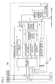
- FIG. 1 is a block diagram showing the configuration of an electronic circuit breaker of Embodiment 1 of the present invention
- FIG. 2 is a view showing a changeover timing chart of a first changeover switch in FIG. 1
- a base (not shown in the drawing) of a circuit breaker 100 stores current transformers 1.
- the current transformers 1 send output currents proportional to the flown currents to the secondary sides of the current transformers 1.
- the outputted currents are inputted to a constant voltage circuit 4 via a rectifire circuit 2; and the constant voltage circuit 4 generates a power source which is for driving an internal microcomputer 6 of the circuit breaker and a tripping device 3 of the circuit breaker.
- a first changeover switch 5 is connected in series between the current transformer 1 and the rectifire circuit 2 and is constantly and periodically switched by a changeover switch control signal from a control signal output circuit 9 of the microcomputer 6, thereby performing changeover between a signal from the current transformer 1 and a test signal from a test signal output circuit 11.
- FIG. 2 shows an example of the changeover timing of the first changeover switch 5.
- the first changeover switch 5 detects the signal from the current transformer 1 when the control signal from the control signal output circuit 9 of the microcomputer 6 is an H level; and the microcomputer 6 obtains its data by the A/D conversion section 7.
- the control signal is an L level
- the first changeover switch 5 switches to detect the signal from the test signal output circuit 11; and the microcomputer 6 obtains its data by the A/D conversion section 7.
- a threshold determination section 61 determines whether or not a value of the signal from the current transformer 1 inputted to the A/D conversion section 7 and a value of the test signal from the test signal output circuit 11 exceed predetermined thresholds of an overcurrent, an instantaneous current, a leakage current, the currents being to be flown to the main circuit; and if the values exceed the thresholds, a tripping signal is outputted from a tripping signal output section 62.
- a second changeover switch 8 different from the first changeover switch 5 is connected between from the tripping signal output section 62 to the tripping device 3.
- Opening/closing of the second changeover switch 8 is performed by the control signal from the control signal output circuit 9 of the microcomputer 6, as in the first changeover switch 5.
- a tripping output determination circuit 10 is connected to the tripping signal output section 62; and the tripping output determination circuit 10 determines whether or not the circuit breaker 100 normally operates along with the control signal from the control signal output circuit 9.
- the test signal output circuit 11 sequentially and repeatedly outputs a signal that exceeds the thresholds of the threshold determination section 61 which sets the predetermined thresholds of the overcurrent, the instantaneous current, and the leakage current; and the tripping output determination circuit 10 determines as a normal operation while the first changeover switch 5 is connected to the test signal output circuit 11 and the tripping signal is outputted from tripping signal output section 62.
- the tripping output determination circuit 10 determines as an abnormal operation and outputs an alarm to the outside of the circuit breaker 100.
- An opening/closing time of the first changeover switch 5 is adjusted by the control signal from the control signal output circuit 9 of the microcomputer 6. Therefore, discrimination can be made whether the signal inputted to the A/D conversion section 7 of the microcomputer 6 is the signal proportional to the current of the main circuit, the current being outputted from the current transformer 1, or the test signal outputted from the test signal output circuit 11; and an erroneous operation of the circuit breaker 100 due to a mixture of the signals can be prevented.
- the second changeover switch 8 is connected in series between the tripping signal output section 62 and the tripping device 3.
- the second changeover switch 8 is opened or closed by the control signal from the control signal output circuit 9 of the microcomputer 6, as in the first changeover switch 5; and when the tripping signal is the signal outputted from the current transformer 1, the second changeover switch 8 is closed and the tripping device 3 is driven to trip the circuit breaker.
- the tripping signal is the signal outputted from the test signal output circuit 11
- the second changeover switch 8 is opened not to operate the tripping device 3.
- the tripping signal is outputted from the tripping signal output section 62; and thus, the tripping signal is fed back to the tripping output determination circuit 10 to determine whether or not the circuit breaker normally operates along with the control signal from the control signal output circuit 9 of the microcomputer 6.
- a path through which the test signal from the test signal output circuit 11 is inputted to the A/D conversion section 7 of the microcomputer 6 is the same as a path through which the secondary output from the current transformer 1 is inputted; and therefore, the operational test can be performed in a state near actual use condition and the configuration can be made without increasing the number of the A/D conversion sections 7 serving as input sections of the microcomputer 6.
- test signal is constantly inputted from the test signal output circuit 11 to the A/D conversion section 7 of the microcomputer 6 and the tripping signal is fed back from the tripping signal output section 62 to the tripping output determination circuit 10; and thus, a special tester is not needed with respect to the function from the current transformer 1 to the tripping signal output section 62, the operational test is automatically performed, and a self-diagnostic function can be imparted.
- the alarm is outputted from the tripping output determination circuit 10 to the outside and the abnormality can be informed to a user; and therefore, the abnormal circuit breaker is not continuously used and reliability of facilities is improved.
- changeover of the first changeover switch 5 is constantly and periodically performed and the current of the main circuit is constantly detected by the current transformer 1; and therefore, even when an overcurrent, a short circuit and/or ground fault accident, and the like occur during the operational test, the circuit breaker 100 can be normally operated and load devices connected to the circuit breaker 100 can be protected.
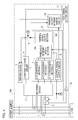
- FIG. 3 is a block diagram showing the configuration of an electronic circuit breaker in Embodiment 2 of the present invention.
- output from the Schmidt trigger circuit 12 is inputted to a threshold determination section 61 of an instantaneous current regardless of opening/closing of the first changeover switch 5 to drive a tripping device 3 by a tripping signal from a tripping signal output section 62.
- Embodiment 1 other configuration is the same as Embodiment 1 and therefore their description will be omitted.
- the Schmidt trigger circuit 12 is provided and the output from the current transformer 1 is detected regardless of the changeover timing of the first changeover switch 5 when the instantaneous large current flows; and therefore, even if a short circuit and/or ground fault accident occurs during the operational test, the circuit breaker 100 can be more reliably operated and load devices connected to the circuit breaker can be protected.
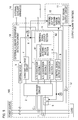
- FIG. 4 is a block diagram showing the configuration of an electronic circuit breaker of Embodiment 3 of the present invention.
- Embodiment 3 is one that the alarm is not outputted to the outside from the tripping output determination circuit 10 in Embodiment 2, but a trip instruction is outputted from a tripping output determination circuit 10 to a tripping device 3.
- other configuration is the same as Embodiment 2 and therefore their description will be omitted.
- the tripping output determination circuit 10 determines as an abnormal operation, the tripping output determination circuit 10 outputs the trip instruction to the tripping device 3 to operate the circuit breaker 100; and therefore, an abnormally operated part of the circuit breaker 100 is automatically and immediately paralleled off, it is possible to avoid a state where load devices connected to the circuit breaker cannot be protected, and reliability of facilities can be further improved.
- FIG. 5 is a block diagram showing the configuration of an electronic circuit breaker in Embodiment 4 of the present invention
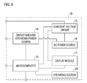
- FIG. 6 is a block diagram showing the configuration of an external auxiliary apparatus shown in FIG. 5 .
- Embodiment 4 is one that performs control of a test signal output circuit by not only a circuit breaker but also by an external auxiliary apparatus in Embodiment 2.
- an external auxiliary apparatus 18 is an independent housing which includes: a DC power source 16, a constant voltage circuit 15, a circuit breaker operating power source 14, a microcomputer 13, and a display module 17 and is an apparatus which can be mounted to any circuit breaker according to user's intention by making it mountable.
- the DC power source 16 is a movable power source such as a dry battery and generates a power source which drives the microcomputer 13 and the display module 17 by the constant voltage circuit 15.
- the constant voltage circuit 15 is connected to the external auxiliary apparatus detection circuit 19 of the circuit breaker to recognize that the external auxiliary apparatus 18 is connected to the internal microcomputer 6 of the circuit breaker.
- the display module 17 displays operation states such as a current value of the main circuit and the determination results of normality/abnormality of a self-diagnostic function.
- the operating section 20 and the display module 17 determine a test current value and the microcomputer 13 controls such that the test signal output circuit 11 outputs a test signal corresponding to the test current value.
- a power source that drives the tripping device 3 is supplied from the circuit breaker operating power source 14 to trip the circuit breaker.
- the power source 16 of the external auxiliary apparatus 18 is not limited to a DC power source such as a dry battery, but the power source 16 may be even a configuration that is provided with an AC/DC conversion circuit in the external auxiliary apparatus 18 to drive by applying an AC voltage from the outside.
- Embodiment 4 in the operational test when the external auxiliary apparatus 18 is connected and the current does not flow in the main circuit, the tripping device 3 is driven by the circuit breaker operating power source 14 provided in an external auxiliary apparatus 18; and therefore, even a mechanical operation that the tripping device 3 normally operates to trip the circuit breaker can be confirmed. Furthermore, instructions can be given so as to output the test signal at optional timing from the microcomputer 13 of the external auxiliary apparatus 18 to the test signal output circuit 11; and therefore, the operational test can be freely performed at a periodic inspection time when facilities seem to be stopped.
- the present invention relates to an electronic circuit breaker provided with a self-diagnostic function capable of periodically and automatically performing an operational test without interrupting power feed to loads and is useful as a circuit breaker which improves an operational availability ratio and reliability of facilities.
Landscapes
- Physics & Mathematics (AREA)
- General Physics & Mathematics (AREA)
- Breakers (AREA)
- Emergency Protection Circuit Devices (AREA)
- Testing Electric Properties And Detecting Electric Faults (AREA)
Applications Claiming Priority (1)
| Application Number | Priority Date | Filing Date | Title |
|---|---|---|---|
| PCT/JP2013/081531 WO2015075815A1 (ja) | 2013-11-22 | 2013-11-22 | 電子式回路遮断器 |
Publications (3)
| Publication Number | Publication Date |
|---|---|
| EP3073281A1 true EP3073281A1 (de) | 2016-09-28 |
| EP3073281A4 EP3073281A4 (de) | 2017-07-05 |
| EP3073281B1 EP3073281B1 (de) | 2020-05-13 |
Family
ID=53179121
Family Applications (1)
| Application Number | Title | Priority Date | Filing Date |
|---|---|---|---|
| EP13897955.4A Active EP3073281B1 (de) | 2013-11-22 | 2013-11-22 | Elektronischer schutzschalter |
Country Status (5)
| Country | Link |
|---|---|
| EP (1) | EP3073281B1 (de) |
| JP (1) | JP6076499B2 (de) |
| KR (1) | KR101699674B1 (de) |
| CN (1) | CN105765393B (de) |
| WO (1) | WO2015075815A1 (de) |
Cited By (1)
| Publication number | Priority date | Publication date | Assignee | Title |
|---|---|---|---|---|
| CN107402324A (zh) * | 2017-09-08 | 2017-11-28 | 威胜电气有限公司 | 基于单电流互感器的供电采样电路、方法及其低压断路器 |
Families Citing this family (7)
| Publication number | Priority date | Publication date | Assignee | Title |
|---|---|---|---|---|
| JP6610173B2 (ja) * | 2015-08-25 | 2019-11-27 | 三菱電機株式会社 | 漏電遮断器 |
| EP3386052B1 (de) * | 2017-04-04 | 2021-06-23 | ABB Schweiz AG | Elektronische schutzvorrichtung |
| CN107272792B (zh) * | 2017-07-05 | 2019-10-29 | 温州大学 | 一种用于断路器测试的恒流源装置 |
| JP6771677B2 (ja) * | 2017-09-28 | 2020-10-21 | 三菱電機株式会社 | 電子式遮断器 |
| KR102126314B1 (ko) * | 2018-03-08 | 2020-06-24 | 엘에스일렉트릭(주) | 누전 차단기 및 이에 착탈 가능한 아크 검출 장치 |
| CN110007261B (zh) * | 2019-03-14 | 2024-03-19 | 国网新疆电力有限公司昌吉供电公司 | 电压互感器一次侧高压熔断器熔断判断装置及其判断方法 |
| WO2021044485A1 (ja) * | 2019-09-02 | 2021-03-11 | 東芝三菱電機産業システム株式会社 | インバータ装置の試験装置 |
Family Cites Families (18)
| Publication number | Priority date | Publication date | Assignee | Title |
|---|---|---|---|---|
| JPH02123912A (ja) * | 1988-10-31 | 1990-05-11 | Omron Tateisi Electron Co | 開閉器制御装置 |
| JP2755697B2 (ja) * | 1989-06-27 | 1998-05-20 | 株式会社東芝 | 保護継電装置 |
| JPH03135321A (ja) * | 1989-10-16 | 1991-06-10 | Toshiba Corp | 回路遮断器 |
| JP3032317B2 (ja) * | 1991-04-11 | 2000-04-17 | 松下冷機株式会社 | 空気調和機の制御装置 |
| FR2700076B1 (fr) * | 1992-12-28 | 1995-03-17 | Merlin Gerin | Déclencheur électronique comportant un dispositif de test. |
| JPH09166634A (ja) | 1995-12-14 | 1997-06-24 | Mitsubishi Electric Corp | 電子式回路遮断器の引外し動作試験装置 |
| JP2000261951A (ja) | 1999-03-05 | 2000-09-22 | Fuji Electric Co Ltd | 過電流保護継電器 |
| KR200186786Y1 (ko) * | 2000-02-08 | 2000-06-15 | 주식회사해정지점 | 의자용 결착 부재의 높낮이 조절 구조 |
| US6421214B1 (en) * | 2000-03-03 | 2002-07-16 | Pass & Seymour, Inc. | Arc fault or ground fault detector with self-test feature |
| EP1207622B1 (de) * | 2000-11-21 | 2013-02-27 | Omron Corporation | Halbleiterrelais-System |
| JP2002345145A (ja) * | 2001-05-18 | 2002-11-29 | Mitsubishi Electric Corp | 回路遮断器 |
| KR200268296Y1 (ko) * | 2001-08-10 | 2002-03-16 | 한홍석 | 휴대용 차단기시험기 |
| JP4715537B2 (ja) * | 2006-02-15 | 2011-07-06 | 富士電機株式会社 | 漏電遮断器 |
| JP4908245B2 (ja) * | 2007-01-26 | 2012-04-04 | 三菱電機株式会社 | 回路遮断器 |
| JP5258670B2 (ja) * | 2009-05-27 | 2013-08-07 | 三菱電機株式会社 | 漏電遮断器 |
| JP5322784B2 (ja) * | 2009-06-08 | 2013-10-23 | 三菱電機株式会社 | 保護継電装置の特性試験システム |
| JP5434835B2 (ja) * | 2010-01-13 | 2014-03-05 | 三菱電機株式会社 | 回路遮断器の電気操作装置 |
| KR101617117B1 (ko) * | 2012-05-21 | 2016-04-29 | 미쓰비시덴키 가부시키가이샤 | 보호 계전 장치의 동작 시험 시스템 |
-
2013
- 2013-11-22 JP JP2015548936A patent/JP6076499B2/ja active Active
- 2013-11-22 WO PCT/JP2013/081531 patent/WO2015075815A1/ja not_active Ceased
- 2013-11-22 KR KR1020167005230A patent/KR101699674B1/ko active Active
- 2013-11-22 EP EP13897955.4A patent/EP3073281B1/de active Active
- 2013-11-22 CN CN201380081095.8A patent/CN105765393B/zh active Active
Cited By (2)
| Publication number | Priority date | Publication date | Assignee | Title |
|---|---|---|---|---|
| CN107402324A (zh) * | 2017-09-08 | 2017-11-28 | 威胜电气有限公司 | 基于单电流互感器的供电采样电路、方法及其低压断路器 |
| CN107402324B (zh) * | 2017-09-08 | 2023-08-15 | 威胜能源技术股份有限公司 | 基于单电流互感器的供电采样电路、方法及其低压断路器 |
Also Published As
| Publication number | Publication date |
|---|---|
| CN105765393B (zh) | 2018-09-11 |
| KR20160039261A (ko) | 2016-04-08 |
| KR101699674B1 (ko) | 2017-01-24 |
| EP3073281B1 (de) | 2020-05-13 |
| CN105765393A (zh) | 2016-07-13 |
| WO2015075815A1 (ja) | 2015-05-28 |
| EP3073281A4 (de) | 2017-07-05 |
| JPWO2015075815A1 (ja) | 2017-03-16 |
| JP6076499B2 (ja) | 2017-02-08 |
Similar Documents
| Publication | Publication Date | Title |
|---|---|---|
| EP3073281B1 (de) | Elektronischer schutzschalter | |
| KR101003814B1 (ko) | 전기적회로 이상감지기능을 갖는 수배전반 및 그 제어방법 | |
| TWI504088B (zh) | Digital protection relays, digital protection relays test equipment and digital protection relays test method | |
| KR101153296B1 (ko) | 직류전원장치나 직류전원선로의 지락 및 누설전류 감시기능을 가지는 직류전원감시기 | |
| KR101553766B1 (ko) | 누전 차단기 | |
| KR101036544B1 (ko) | 전력계통의 차단기 감시 장치 | |
| US10613132B2 (en) | Arc fault detection unit | |
| US8427794B2 (en) | Multi-pole arc-fault circuit interrupter | |
| JP5082961B2 (ja) | 配電盤の交流電圧回路試験装置およびその方法 | |
| EP3830920B1 (de) | Verfahren und vorrichtung zur überwachung eines spannungswandlers | |
| KR100972274B1 (ko) | 누전차단기 | |
| US6407897B1 (en) | Network protector with diagnostics | |
| JP6509029B2 (ja) | 分電盤 | |
| KR101069637B1 (ko) | 과전류 보호 방법 및 그 장치 | |
| US10916930B2 (en) | Electrical power systems | |
| KR20140086279A (ko) | 직류전력 감시가 가능한 분전반 | |
| KR101816896B1 (ko) | 배전선로 절연 성능 자동 진단 시스템 및 방법 | |
| EP1919053A2 (de) | Statusüberwachungsvorrichtung für Schutzschalter | |
| KR102497264B1 (ko) | 전력회로 이상상태 감시 시스템 | |
| KR20200122753A (ko) | 다회로차단기 시험 장치 | |
| KR101668434B1 (ko) | 조작전원을 이용한 전력설비의 정상유무 감시 장치 | |
| KR102663907B1 (ko) | 계기용 변류기 2차개방 설치적용형 감시시스템 | |
| KR20210029057A (ko) | IoT 기술 기반의 CT/VT 보호장치를 구비한 수배전반용 단자대 | |
| KR20170117750A (ko) | 계통 보호용 계전기 | |
| JP2022108963A (ja) | 保護継電器の接続状態切替回路 |
Legal Events
| Date | Code | Title | Description |
|---|---|---|---|
| PUAI | Public reference made under article 153(3) epc to a published international application that has entered the european phase |
Free format text: ORIGINAL CODE: 0009012 |
|
| 17P | Request for examination filed |
Effective date: 20151222 |
|
| AK | Designated contracting states |
Kind code of ref document: A1 Designated state(s): AL AT BE BG CH CY CZ DE DK EE ES FI FR GB GR HR HU IE IS IT LI LT LU LV MC MK MT NL NO PL PT RO RS SE SI SK SM TR |
|
| AX | Request for extension of the european patent |
Extension state: BA ME |
|
| DAX | Request for extension of the european patent (deleted) | ||
| REG | Reference to a national code |
Ref country code: DE Ref legal event code: R079 Ref document number: 602013069162 Country of ref document: DE Free format text: PREVIOUS MAIN CLASS: G01R0031327000 Ipc: H02H0003040000 |
|
| RIC1 | Information provided on ipc code assigned before grant |
Ipc: G01R 31/333 20060101ALI20170524BHEP Ipc: H02H 3/05 20060101ALI20170524BHEP Ipc: G01R 31/327 20060101ALI20170524BHEP Ipc: H02H 3/04 20060101AFI20170524BHEP |
|
| A4 | Supplementary search report drawn up and despatched |
Effective date: 20170602 |
|
| GRAP | Despatch of communication of intention to grant a patent |
Free format text: ORIGINAL CODE: EPIDOSNIGR1 |
|
| STAA | Information on the status of an ep patent application or granted ep patent |
Free format text: STATUS: GRANT OF PATENT IS INTENDED |
|
| INTG | Intention to grant announced |
Effective date: 20191209 |
|
| GRAS | Grant fee paid |
Free format text: ORIGINAL CODE: EPIDOSNIGR3 |
|
| GRAJ | Information related to disapproval of communication of intention to grant by the applicant or resumption of examination proceedings by the epo deleted |
Free format text: ORIGINAL CODE: EPIDOSDIGR1 |
|
| GRAL | Information related to payment of fee for publishing/printing deleted |
Free format text: ORIGINAL CODE: EPIDOSDIGR3 |
|
| STAA | Information on the status of an ep patent application or granted ep patent |
Free format text: STATUS: REQUEST FOR EXAMINATION WAS MADE |
|
| GRAP | Despatch of communication of intention to grant a patent |
Free format text: ORIGINAL CODE: EPIDOSNIGR1 |
|
| STAA | Information on the status of an ep patent application or granted ep patent |
Free format text: STATUS: GRANT OF PATENT IS INTENDED |
|
| INTC | Intention to grant announced (deleted) | ||
| GRAA | (expected) grant |
Free format text: ORIGINAL CODE: 0009210 |
|
| STAA | Information on the status of an ep patent application or granted ep patent |
Free format text: STATUS: THE PATENT HAS BEEN GRANTED |
|
| INTG | Intention to grant announced |
Effective date: 20200317 |
|
| AK | Designated contracting states |
Kind code of ref document: B1 Designated state(s): AL AT BE BG CH CY CZ DE DK EE ES FI FR GB GR HR HU IE IS IT LI LT LU LV MC MK MT NL NO PL PT RO RS SE SI SK SM TR |
|
| REG | Reference to a national code |
Ref country code: GB Ref legal event code: FG4D |
|
| REG | Reference to a national code |
Ref country code: CH Ref legal event code: EP |
|
| REG | Reference to a national code |
Ref country code: DE Ref legal event code: R096 Ref document number: 602013069162 Country of ref document: DE |
|
| REG | Reference to a national code |
Ref country code: AT Ref legal event code: REF Ref document number: 1271503 Country of ref document: AT Kind code of ref document: T Effective date: 20200615 |
|
| REG | Reference to a national code |
Ref country code: LT Ref legal event code: MG4D |
|
| REG | Reference to a national code |
Ref country code: NL Ref legal event code: MP Effective date: 20200513 |
|
| PG25 | Lapsed in a contracting state [announced via postgrant information from national office to epo] |
Ref country code: LT Free format text: LAPSE BECAUSE OF FAILURE TO SUBMIT A TRANSLATION OF THE DESCRIPTION OR TO PAY THE FEE WITHIN THE PRESCRIBED TIME-LIMIT Effective date: 20200513 Ref country code: PT Free format text: LAPSE BECAUSE OF FAILURE TO SUBMIT A TRANSLATION OF THE DESCRIPTION OR TO PAY THE FEE WITHIN THE PRESCRIBED TIME-LIMIT Effective date: 20200914 Ref country code: FI Free format text: LAPSE BECAUSE OF FAILURE TO SUBMIT A TRANSLATION OF THE DESCRIPTION OR TO PAY THE FEE WITHIN THE PRESCRIBED TIME-LIMIT Effective date: 20200513 Ref country code: GR Free format text: LAPSE BECAUSE OF FAILURE TO SUBMIT A TRANSLATION OF THE DESCRIPTION OR TO PAY THE FEE WITHIN THE PRESCRIBED TIME-LIMIT Effective date: 20200814 Ref country code: SE Free format text: LAPSE BECAUSE OF FAILURE TO SUBMIT A TRANSLATION OF THE DESCRIPTION OR TO PAY THE FEE WITHIN THE PRESCRIBED TIME-LIMIT Effective date: 20200513 Ref country code: IS Free format text: LAPSE BECAUSE OF FAILURE TO SUBMIT A TRANSLATION OF THE DESCRIPTION OR TO PAY THE FEE WITHIN THE PRESCRIBED TIME-LIMIT Effective date: 20200913 Ref country code: NO Free format text: LAPSE BECAUSE OF FAILURE TO SUBMIT A TRANSLATION OF THE DESCRIPTION OR TO PAY THE FEE WITHIN THE PRESCRIBED TIME-LIMIT Effective date: 20200813 |
|
| PG25 | Lapsed in a contracting state [announced via postgrant information from national office to epo] |
Ref country code: RS Free format text: LAPSE BECAUSE OF FAILURE TO SUBMIT A TRANSLATION OF THE DESCRIPTION OR TO PAY THE FEE WITHIN THE PRESCRIBED TIME-LIMIT Effective date: 20200513 Ref country code: HR Free format text: LAPSE BECAUSE OF FAILURE TO SUBMIT A TRANSLATION OF THE DESCRIPTION OR TO PAY THE FEE WITHIN THE PRESCRIBED TIME-LIMIT Effective date: 20200513 Ref country code: BG Free format text: LAPSE BECAUSE OF FAILURE TO SUBMIT A TRANSLATION OF THE DESCRIPTION OR TO PAY THE FEE WITHIN THE PRESCRIBED TIME-LIMIT Effective date: 20200813 Ref country code: LV Free format text: LAPSE BECAUSE OF FAILURE TO SUBMIT A TRANSLATION OF THE DESCRIPTION OR TO PAY THE FEE WITHIN THE PRESCRIBED TIME-LIMIT Effective date: 20200513 |
|
| REG | Reference to a national code |
Ref country code: AT Ref legal event code: MK05 Ref document number: 1271503 Country of ref document: AT Kind code of ref document: T Effective date: 20200513 |
|
| PG25 | Lapsed in a contracting state [announced via postgrant information from national office to epo] |
Ref country code: AL Free format text: LAPSE BECAUSE OF FAILURE TO SUBMIT A TRANSLATION OF THE DESCRIPTION OR TO PAY THE FEE WITHIN THE PRESCRIBED TIME-LIMIT Effective date: 20200513 Ref country code: NL Free format text: LAPSE BECAUSE OF FAILURE TO SUBMIT A TRANSLATION OF THE DESCRIPTION OR TO PAY THE FEE WITHIN THE PRESCRIBED TIME-LIMIT Effective date: 20200513 |
|
| PG25 | Lapsed in a contracting state [announced via postgrant information from national office to epo] |
Ref country code: IT Free format text: LAPSE BECAUSE OF FAILURE TO SUBMIT A TRANSLATION OF THE DESCRIPTION OR TO PAY THE FEE WITHIN THE PRESCRIBED TIME-LIMIT Effective date: 20200513 Ref country code: ES Free format text: LAPSE BECAUSE OF FAILURE TO SUBMIT A TRANSLATION OF THE DESCRIPTION OR TO PAY THE FEE WITHIN THE PRESCRIBED TIME-LIMIT Effective date: 20200513 Ref country code: CZ Free format text: LAPSE BECAUSE OF FAILURE TO SUBMIT A TRANSLATION OF THE DESCRIPTION OR TO PAY THE FEE WITHIN THE PRESCRIBED TIME-LIMIT Effective date: 20200513 Ref country code: RO Free format text: LAPSE BECAUSE OF FAILURE TO SUBMIT A TRANSLATION OF THE DESCRIPTION OR TO PAY THE FEE WITHIN THE PRESCRIBED TIME-LIMIT Effective date: 20200513 Ref country code: EE Free format text: LAPSE BECAUSE OF FAILURE TO SUBMIT A TRANSLATION OF THE DESCRIPTION OR TO PAY THE FEE WITHIN THE PRESCRIBED TIME-LIMIT Effective date: 20200513 Ref country code: DK Free format text: LAPSE BECAUSE OF FAILURE TO SUBMIT A TRANSLATION OF THE DESCRIPTION OR TO PAY THE FEE WITHIN THE PRESCRIBED TIME-LIMIT Effective date: 20200513 Ref country code: AT Free format text: LAPSE BECAUSE OF FAILURE TO SUBMIT A TRANSLATION OF THE DESCRIPTION OR TO PAY THE FEE WITHIN THE PRESCRIBED TIME-LIMIT Effective date: 20200513 Ref country code: SM Free format text: LAPSE BECAUSE OF FAILURE TO SUBMIT A TRANSLATION OF THE DESCRIPTION OR TO PAY THE FEE WITHIN THE PRESCRIBED TIME-LIMIT Effective date: 20200513 |
|
| REG | Reference to a national code |
Ref country code: DE Ref legal event code: R097 Ref document number: 602013069162 Country of ref document: DE |
|
| PG25 | Lapsed in a contracting state [announced via postgrant information from national office to epo] |
Ref country code: SK Free format text: LAPSE BECAUSE OF FAILURE TO SUBMIT A TRANSLATION OF THE DESCRIPTION OR TO PAY THE FEE WITHIN THE PRESCRIBED TIME-LIMIT Effective date: 20200513 Ref country code: PL Free format text: LAPSE BECAUSE OF FAILURE TO SUBMIT A TRANSLATION OF THE DESCRIPTION OR TO PAY THE FEE WITHIN THE PRESCRIBED TIME-LIMIT Effective date: 20200513 |
|
| PLBE | No opposition filed within time limit |
Free format text: ORIGINAL CODE: 0009261 |
|
| STAA | Information on the status of an ep patent application or granted ep patent |
Free format text: STATUS: NO OPPOSITION FILED WITHIN TIME LIMIT |
|
| 26N | No opposition filed |
Effective date: 20210216 |
|
| PG25 | Lapsed in a contracting state [announced via postgrant information from national office to epo] |
Ref country code: SI Free format text: LAPSE BECAUSE OF FAILURE TO SUBMIT A TRANSLATION OF THE DESCRIPTION OR TO PAY THE FEE WITHIN THE PRESCRIBED TIME-LIMIT Effective date: 20200513 |
|
| PG25 | Lapsed in a contracting state [announced via postgrant information from national office to epo] |
Ref country code: MC Free format text: LAPSE BECAUSE OF FAILURE TO SUBMIT A TRANSLATION OF THE DESCRIPTION OR TO PAY THE FEE WITHIN THE PRESCRIBED TIME-LIMIT Effective date: 20200513 |
|
| REG | Reference to a national code |
Ref country code: CH Ref legal event code: PL |
|
| GBPC | Gb: european patent ceased through non-payment of renewal fee |
Effective date: 20201122 |
|
| PG25 | Lapsed in a contracting state [announced via postgrant information from national office to epo] |
Ref country code: LU Free format text: LAPSE BECAUSE OF NON-PAYMENT OF DUE FEES Effective date: 20201122 |
|
| REG | Reference to a national code |
Ref country code: BE Ref legal event code: MM Effective date: 20201130 |
|
| PG25 | Lapsed in a contracting state [announced via postgrant information from national office to epo] |
Ref country code: LI Free format text: LAPSE BECAUSE OF NON-PAYMENT OF DUE FEES Effective date: 20201130 Ref country code: CH Free format text: LAPSE BECAUSE OF NON-PAYMENT OF DUE FEES Effective date: 20201130 |
|
| PG25 | Lapsed in a contracting state [announced via postgrant information from national office to epo] |
Ref country code: IE Free format text: LAPSE BECAUSE OF NON-PAYMENT OF DUE FEES Effective date: 20201122 |
|
| PG25 | Lapsed in a contracting state [announced via postgrant information from national office to epo] |
Ref country code: GB Free format text: LAPSE BECAUSE OF NON-PAYMENT OF DUE FEES Effective date: 20201122 |
|
| PG25 | Lapsed in a contracting state [announced via postgrant information from national office to epo] |
Ref country code: TR Free format text: LAPSE BECAUSE OF FAILURE TO SUBMIT A TRANSLATION OF THE DESCRIPTION OR TO PAY THE FEE WITHIN THE PRESCRIBED TIME-LIMIT Effective date: 20200513 Ref country code: MT Free format text: LAPSE BECAUSE OF FAILURE TO SUBMIT A TRANSLATION OF THE DESCRIPTION OR TO PAY THE FEE WITHIN THE PRESCRIBED TIME-LIMIT Effective date: 20200513 Ref country code: CY Free format text: LAPSE BECAUSE OF FAILURE TO SUBMIT A TRANSLATION OF THE DESCRIPTION OR TO PAY THE FEE WITHIN THE PRESCRIBED TIME-LIMIT Effective date: 20200513 |
|
| PG25 | Lapsed in a contracting state [announced via postgrant information from national office to epo] |
Ref country code: MK Free format text: LAPSE BECAUSE OF FAILURE TO SUBMIT A TRANSLATION OF THE DESCRIPTION OR TO PAY THE FEE WITHIN THE PRESCRIBED TIME-LIMIT Effective date: 20200513 |
|
| PG25 | Lapsed in a contracting state [announced via postgrant information from national office to epo] |
Ref country code: BE Free format text: LAPSE BECAUSE OF NON-PAYMENT OF DUE FEES Effective date: 20201130 |
|
| REG | Reference to a national code |
Ref country code: DE Ref legal event code: R084 Ref document number: 602013069162 Country of ref document: DE |
|
| P01 | Opt-out of the competence of the unified patent court (upc) registered |
Effective date: 20230512 |
|
| PGFP | Annual fee paid to national office [announced via postgrant information from national office to epo] |
Ref country code: DE Payment date: 20241001 Year of fee payment: 12 |
|
| PGFP | Annual fee paid to national office [announced via postgrant information from national office to epo] |
Ref country code: FR Payment date: 20241001 Year of fee payment: 12 |
|
| PG25 | Lapsed in a contracting state [announced via postgrant information from national office to epo] |
Ref country code: IS Free format text: LAPSE BECAUSE OF NON-PAYMENT OF DUE FEES Effective date: 20200913 |