EP3072663A1 - Spritzgussteil mit einem basisteil und einem daran befestigten polsternden formteil und verfahren zu seiner herstellung - Google Patents
Spritzgussteil mit einem basisteil und einem daran befestigten polsternden formteil und verfahren zu seiner herstellung Download PDFInfo
- Publication number
- EP3072663A1 EP3072663A1 EP16153188.4A EP16153188A EP3072663A1 EP 3072663 A1 EP3072663 A1 EP 3072663A1 EP 16153188 A EP16153188 A EP 16153188A EP 3072663 A1 EP3072663 A1 EP 3072663A1
- Authority
- EP
- European Patent Office
- Prior art keywords
- component
- injection
- hard component
- mold
- base part
- Prior art date
- Legal status (The legal status is an assumption and is not a legal conclusion. Google has not performed a legal analysis and makes no representation as to the accuracy of the status listed.)
- Granted
Links
Images

Classifications
-
- B—PERFORMING OPERATIONS; TRANSPORTING
- B32—LAYERED PRODUCTS
- B32B—LAYERED PRODUCTS, i.e. PRODUCTS BUILT-UP OF STRATA OF FLAT OR NON-FLAT, e.g. CELLULAR OR HONEYCOMB, FORM
- B32B3/00—Layered products comprising a layer with external or internal discontinuities or unevennesses, or a layer of non-planar shape; Layered products comprising a layer having particular features of form
- B32B3/02—Layered products comprising a layer with external or internal discontinuities or unevennesses, or a layer of non-planar shape; Layered products comprising a layer having particular features of form characterised by features of form at particular places, e.g. in edge regions
- B32B3/06—Layered products comprising a layer with external or internal discontinuities or unevennesses, or a layer of non-planar shape; Layered products comprising a layer having particular features of form characterised by features of form at particular places, e.g. in edge regions for securing layers together; for attaching the product to another member, e.g. to a support, or to another product, e.g. groove/tongue, interlocking
-
- B—PERFORMING OPERATIONS; TRANSPORTING
- B29—WORKING OF PLASTICS; WORKING OF SUBSTANCES IN A PLASTIC STATE IN GENERAL
- B29C—SHAPING OR JOINING OF PLASTICS; SHAPING OF MATERIAL IN A PLASTIC STATE, NOT OTHERWISE PROVIDED FOR; AFTER-TREATMENT OF THE SHAPED PRODUCTS, e.g. REPAIRING
- B29C45/00—Injection moulding, i.e. forcing the required volume of moulding material through a nozzle into a closed mould; Apparatus therefor
- B29C45/14—Injection moulding, i.e. forcing the required volume of moulding material through a nozzle into a closed mould; Apparatus therefor incorporating preformed parts or layers, e.g. injection moulding around inserts or for coating articles
-
- B—PERFORMING OPERATIONS; TRANSPORTING
- B29—WORKING OF PLASTICS; WORKING OF SUBSTANCES IN A PLASTIC STATE IN GENERAL
- B29C—SHAPING OR JOINING OF PLASTICS; SHAPING OF MATERIAL IN A PLASTIC STATE, NOT OTHERWISE PROVIDED FOR; AFTER-TREATMENT OF THE SHAPED PRODUCTS, e.g. REPAIRING
- B29C45/00—Injection moulding, i.e. forcing the required volume of moulding material through a nozzle into a closed mould; Apparatus therefor
- B29C45/14—Injection moulding, i.e. forcing the required volume of moulding material through a nozzle into a closed mould; Apparatus therefor incorporating preformed parts or layers, e.g. injection moulding around inserts or for coating articles
- B29C45/14336—Coating a portion of the article, e.g. the edge of the article
-
- B—PERFORMING OPERATIONS; TRANSPORTING
- B29—WORKING OF PLASTICS; WORKING OF SUBSTANCES IN A PLASTIC STATE IN GENERAL
- B29C—SHAPING OR JOINING OF PLASTICS; SHAPING OF MATERIAL IN A PLASTIC STATE, NOT OTHERWISE PROVIDED FOR; AFTER-TREATMENT OF THE SHAPED PRODUCTS, e.g. REPAIRING
- B29C45/00—Injection moulding, i.e. forcing the required volume of moulding material through a nozzle into a closed mould; Apparatus therefor
- B29C45/14—Injection moulding, i.e. forcing the required volume of moulding material through a nozzle into a closed mould; Apparatus therefor incorporating preformed parts or layers, e.g. injection moulding around inserts or for coating articles
- B29C45/14336—Coating a portion of the article, e.g. the edge of the article
- B29C45/14418—Sealing means between mould and article
-
- B—PERFORMING OPERATIONS; TRANSPORTING
- B29—WORKING OF PLASTICS; WORKING OF SUBSTANCES IN A PLASTIC STATE IN GENERAL
- B29C—SHAPING OR JOINING OF PLASTICS; SHAPING OF MATERIAL IN A PLASTIC STATE, NOT OTHERWISE PROVIDED FOR; AFTER-TREATMENT OF THE SHAPED PRODUCTS, e.g. REPAIRING
- B29C45/00—Injection moulding, i.e. forcing the required volume of moulding material through a nozzle into a closed mould; Apparatus therefor
- B29C45/14—Injection moulding, i.e. forcing the required volume of moulding material through a nozzle into a closed mould; Apparatus therefor incorporating preformed parts or layers, e.g. injection moulding around inserts or for coating articles
- B29C45/14778—Injection moulding, i.e. forcing the required volume of moulding material through a nozzle into a closed mould; Apparatus therefor incorporating preformed parts or layers, e.g. injection moulding around inserts or for coating articles the article consisting of a material with particular properties, e.g. porous, brittle
-
- B—PERFORMING OPERATIONS; TRANSPORTING
- B29—WORKING OF PLASTICS; WORKING OF SUBSTANCES IN A PLASTIC STATE IN GENERAL
- B29C—SHAPING OR JOINING OF PLASTICS; SHAPING OF MATERIAL IN A PLASTIC STATE, NOT OTHERWISE PROVIDED FOR; AFTER-TREATMENT OF THE SHAPED PRODUCTS, e.g. REPAIRING
- B29C45/00—Injection moulding, i.e. forcing the required volume of moulding material through a nozzle into a closed mould; Apparatus therefor
- B29C45/14—Injection moulding, i.e. forcing the required volume of moulding material through a nozzle into a closed mould; Apparatus therefor incorporating preformed parts or layers, e.g. injection moulding around inserts or for coating articles
- B29C45/14836—Preventing damage of inserts during injection, e.g. collapse of hollow inserts, breakage
-
- B—PERFORMING OPERATIONS; TRANSPORTING
- B32—LAYERED PRODUCTS
- B32B—LAYERED PRODUCTS, i.e. PRODUCTS BUILT-UP OF STRATA OF FLAT OR NON-FLAT, e.g. CELLULAR OR HONEYCOMB, FORM
- B32B3/00—Layered products comprising a layer with external or internal discontinuities or unevennesses, or a layer of non-planar shape; Layered products comprising a layer having particular features of form
- B32B3/02—Layered products comprising a layer with external or internal discontinuities or unevennesses, or a layer of non-planar shape; Layered products comprising a layer having particular features of form characterised by features of form at particular places, e.g. in edge regions
-
- B—PERFORMING OPERATIONS; TRANSPORTING
- B29—WORKING OF PLASTICS; WORKING OF SUBSTANCES IN A PLASTIC STATE IN GENERAL
- B29C—SHAPING OR JOINING OF PLASTICS; SHAPING OF MATERIAL IN A PLASTIC STATE, NOT OTHERWISE PROVIDED FOR; AFTER-TREATMENT OF THE SHAPED PRODUCTS, e.g. REPAIRING
- B29C45/00—Injection moulding, i.e. forcing the required volume of moulding material through a nozzle into a closed mould; Apparatus therefor
- B29C45/14—Injection moulding, i.e. forcing the required volume of moulding material through a nozzle into a closed mould; Apparatus therefor incorporating preformed parts or layers, e.g. injection moulding around inserts or for coating articles
- B29C2045/1486—Details, accessories and auxiliary operations
- B29C2045/14934—Preventing penetration of injected material between insert and adjacent mould wall
-
- B—PERFORMING OPERATIONS; TRANSPORTING
- B29—WORKING OF PLASTICS; WORKING OF SUBSTANCES IN A PLASTIC STATE IN GENERAL
- B29C—SHAPING OR JOINING OF PLASTICS; SHAPING OF MATERIAL IN A PLASTIC STATE, NOT OTHERWISE PROVIDED FOR; AFTER-TREATMENT OF THE SHAPED PRODUCTS, e.g. REPAIRING
- B29C45/00—Injection moulding, i.e. forcing the required volume of moulding material through a nozzle into a closed mould; Apparatus therefor
- B29C45/16—Making multilayered or multicoloured articles
- B29C45/1615—The materials being injected at different moulding stations
-
- B—PERFORMING OPERATIONS; TRANSPORTING
- B29—WORKING OF PLASTICS; WORKING OF SUBSTANCES IN A PLASTIC STATE IN GENERAL
- B29K—INDEXING SCHEME ASSOCIATED WITH SUBCLASSES B29B, B29C OR B29D, RELATING TO MOULDING MATERIALS OR TO MATERIALS FOR MOULDS, REINFORCEMENTS, FILLERS OR PREFORMED PARTS, e.g. INSERTS
- B29K2675/00—Use of PU, i.e. polyureas or polyurethanes or derivatives thereof, for preformed parts, e.g. for inserts
-
- B—PERFORMING OPERATIONS; TRANSPORTING
- B29—WORKING OF PLASTICS; WORKING OF SUBSTANCES IN A PLASTIC STATE IN GENERAL
- B29L—INDEXING SCHEME ASSOCIATED WITH SUBCLASS B29C, RELATING TO PARTICULAR ARTICLES
- B29L2009/00—Layered products
-
- Y—GENERAL TAGGING OF NEW TECHNOLOGICAL DEVELOPMENTS; GENERAL TAGGING OF CROSS-SECTIONAL TECHNOLOGIES SPANNING OVER SEVERAL SECTIONS OF THE IPC; TECHNICAL SUBJECTS COVERED BY FORMER USPC CROSS-REFERENCE ART COLLECTIONS [XRACs] AND DIGESTS
- Y10—TECHNICAL SUBJECTS COVERED BY FORMER USPC
- Y10T—TECHNICAL SUBJECTS COVERED BY FORMER US CLASSIFICATION
- Y10T428/00—Stock material or miscellaneous articles
- Y10T428/24—Structurally defined web or sheet [e.g., overall dimension, etc.]
- Y10T428/24174—Structurally defined web or sheet [e.g., overall dimension, etc.] including sheet or component perpendicular to plane of web or sheet
-
- Y—GENERAL TAGGING OF NEW TECHNOLOGICAL DEVELOPMENTS; GENERAL TAGGING OF CROSS-SECTIONAL TECHNOLOGIES SPANNING OVER SEVERAL SECTIONS OF THE IPC; TECHNICAL SUBJECTS COVERED BY FORMER USPC CROSS-REFERENCE ART COLLECTIONS [XRACs] AND DIGESTS
- Y10—TECHNICAL SUBJECTS COVERED BY FORMER USPC
- Y10T—TECHNICAL SUBJECTS COVERED BY FORMER US CLASSIFICATION
- Y10T428/00—Stock material or miscellaneous articles
- Y10T428/24—Structurally defined web or sheet [e.g., overall dimension, etc.]
- Y10T428/24174—Structurally defined web or sheet [e.g., overall dimension, etc.] including sheet or component perpendicular to plane of web or sheet
- Y10T428/24182—Inward from edge of web or sheet
-
- Y—GENERAL TAGGING OF NEW TECHNOLOGICAL DEVELOPMENTS; GENERAL TAGGING OF CROSS-SECTIONAL TECHNOLOGIES SPANNING OVER SEVERAL SECTIONS OF THE IPC; TECHNICAL SUBJECTS COVERED BY FORMER USPC CROSS-REFERENCE ART COLLECTIONS [XRACs] AND DIGESTS
- Y10—TECHNICAL SUBJECTS COVERED BY FORMER USPC
- Y10T—TECHNICAL SUBJECTS COVERED BY FORMER US CLASSIFICATION
- Y10T428/00—Stock material or miscellaneous articles
- Y10T428/24—Structurally defined web or sheet [e.g., overall dimension, etc.]
- Y10T428/24777—Edge feature
Definitions
- the invention relates to an injection molded part, formed from a base part produced by injection molding and a cushioning molded part attached thereto.
- the choice of material for injection molded parts takes many aspects, including in particular the desired stability, strength, elasticity and flexibility of the injection-molded part to be produced.
- materials selected under the respective aspects can not meet all the requirements, in particular if the injection-molded part is intended to rest on a body.
- the material of the injection molded part can then lead to chafing and similar damage due to relative movements.
- a cushioning molding which consists of a softer material.
- a molding of a gel is suitable. Since the soft molded part can not withstand dimensionally stable injection molding pressures, it is usually prepared separately and subsequently applied to the injection-molded part produced by injection molding, for example glued. This process is cumbersome and makes the injection molded part more expensive.
- the present invention has for its object to provide an injection molded part of the type mentioned, in which a separate effort for the connection of the base part and cushioning molding is not needed.
- the cushioning molding is formed with a soft, cast gel body (soft component), which on a boundary surface with a harder, but flexible and elastically deformable material (hard component) is completely covered, which forms a laterally projecting beyond the gel body peripheral flange-like edge, wherein the cushioning molding is connected via the hard component with the base part.
- soft component soft, cast gel body
- hard component hard component
- the injection-molded part according to the invention thus has a cushioning molded part, which is formed in two parts.
- the actual cushioning effect is effected by a soft component formed by a soft cast gel body.
- this soft component is completely covered by a hard component of the cushioning molding.
- the hard component has a greater hardness than the soft component, but is also flexible and elastically deformable.
- the hard component is preferably formed from a hard gel, which is similar in structure to the gel of the soft component, so that the soft component and the hard component in the liquid state combine well with each other materially without the need for an adhesive.
- the hard component protrudes laterally beyond the gel body with a circumferential flange-like edge, with which the required demarcation of the soft cast gel body with respect to the injected material of the base part takes place in the injection mold.
- the circumferential flange-like edge allows complete sealing of the filled by the cast gel body space, which is formed by a negative mold in the injection mold. Due to the applied hard component of the cushioning molding this is able to withstand the subsequent injection pressure for the base part dimensionally stable.
- the material of the hard component in the region of the sealing circumferential edge is strongly compressed, for example to a thickness of 30% of the initial thickness of the material.
- the material thickness of the circumferential flange-like edge is 1 mm, this edge is clamped between two mold parts and compressed to, for example, 0.3 mm by the closing pressure of the injection mold.
- the material of the hard component must be selected so that it can withstand this elastic deformation and the injection pressure. It may be useful if the hard component consists of a filled hard gel, in particular a filled with a metal oxide or a metalloid oxide, in particular silica, hard gel, in particular a filled polyurethane gel, as by EP 1 125 975 B1 is known. In a preferred embodiment, the hard gel has a hardness of 40 Shore A.
- Preferred combinations of materials for the soft component and the hard component are PU softgel with PU hard gel and silicone softgel with silicone hard gel.
- other combinations are also possible, for example a PU foam as soft component with a PU hard gel as hard component.
- the soft component when using a softgels made of polyurethane (PU), which tends to stick, it is advantageous if the soft component is completely enclosed by a cover outside the boundary surface covered by the hard component.
- the cover film is expediently a high-performance TPU film, as sold, for example, under the trademarks "Platilon” or “Dureflex”.
- the film combines in the application of the material of the hard component with the hard component, so that it additionally fulfills the function to keep the soft component even under load in a limited volume, so that the soft component returns to the initial shape after a load.
- it is expedient vorzuverformen the cover, for example by deep drawing.
- the surface of the hard component remote from the soft component is likewise covered with a foil.
- This film must be compatible with the injection molding material.
- the cover of the hard component may also be a TPU film, which may differ from the TPU film of the soft component.
- injection molding material for the base part can also find a TPU use.
- other materials such as silicone, polycarbonate, etc., are possible.
- the production of the injection-molded part according to the invention with the molded cushioning molded part takes place in that first the soft component of the cushioning molded part is poured in a suitable mold, wherein subsequently the hard component is applied.
- the molding is introduced with its soft component in a corresponding negative mold, which forms a first mold of an injection mold, so that the peripheral edge of the hard component sealingly rests on a surface closing the negative mold, when the injection mold is closed by a second mold and the peripheral edge with the Clamping pressure of the injection mold clamped.
- the injection molding operation is carried out for the base part, wherein the soft component in the negative mold is shielded by the hard component against the injected material of the base part and the hard component is overmolded with the material of the base part.
- connection between the base part and the cushioning shaped part takes place on the hard component, while the soft component remains shielded from the material of the base part by the sealing by means of the hard component.
- connection between the hard component and the material of the base part takes place exclusively in the region of the narrow free edge of the hard component of the cushioning molded part, ie if the surface of the hard component facing away from the soft component remains free.
- the film covering the soft component For applying the film covering the soft component, it is first molded into the casting mold for the soft component, for example by deep drawing, so that the soft component is poured into the casting mold lined with the film. Subsequently, the hard component is applied, preferably also by a casting process and preferably still while the soft component is still in its casting mold.
- the crosslinking of the two components can be carried out, for example, in polyurethane reactive. Subsequently, the cushioning molding is inserted into the negative mold of the injection mold and carried out the injection molding of the base part.
- the area of the hard component facing away from the soft component is still covered with a cover film before performing the injection molding process.
- a cover film is particularly useful when the connection between the cushioning molding and the Base part, for example, only in the region of the narrow free edge of the hard component of the cushioning molding, so that the remote from the soft component surface of the hard component is not covered by the material of the base part and therefore remains free.
- the film then avoids a potentially unpleasant sticky surface of the injection molded part in the region of the hard component of the cushioning molding.
- the application of the film is preferably carried out prior to insertion into the injection mold, in particular still in the mold for the soft component after application, preferably pouring, the hard component.
- FIG. 1 illustrated embodiment of a cushioning molded part 1 consists of a soft component 2, which may be formed of a polyurethane softgel and a hard component 3, which completely covers one side - here a bottom - the soft component and the contour of the soft component with a circumferential, flange-like edge 4 stands out.
- the soft component 2 is covered in the illustrated embodiment on all sides that are not covered by the hard component 3, with a pre-formed film 5.
- the film 5 is preferably connected to the peripheral flange-like edge 4 of the hard component 3 with the latter, so that the film 5 with the hard component 3 encloses a space filled by the soft component 2.
- the top view in FIG. 1 b) illustrates that the soft component 2 and the hard component 3 may have an elongated shape.
- all possible shapes for the soft component 2 and the hard component 3 are possible, as long as the hard component 3, the soft component 2 with may surround a circumferential flange-like edge 4, whose function will be explained in more detail below.
- FIG. 2 shows a side view and a plan view of an injection molded part, which consists of the cushioning molding 1 and a base part 6.
- the base part 6 is shown here only as an exemplary embodiment in a substantially rectangular, elongated shape, but may have any desired design. In particular, the base part 6 does not necessarily have to be flat. It may also have more complicated shapes, such as a goggle shape for an eye mask.
- the base part 6 can also be designed in the shape of a frame, wherein the cushioning molding 1 can cushion an inner edge and / or outer edge of the frame part. In the in FIG. 2 illustrated embodiment, the base part molded latching hooks 7, with which the base part 6 and the associated with him cushioning molding 1 is snapped into a receptacle.
- the base part 6 is produced by injection molding, wherein the cushioning molding 1 is connected to the base part 6 during the injection molding process.
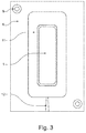
- FIG. 3 shows a plan view of a first mold piece 8 of an injection molding tool.
- the first fitting 8 forms a rectangular lower mold part, which at two diagonally opposite corners with guide pin 9 for exact positioning to a second mold 10 (upper mold part; FIG. 4 ) is provided.
- first fitting 8 is an injection molding cavity 11 is formed, with which the base part 6 is formed.
- Centrally located in the Spritzgusskavmaschine 11 is the inserted cushioning molding 1, which has preferably been prepared in advance as a cast molding.
- FIG. 3 Furthermore, a sprue channel 12 can be seen, via which the injection molding cavity 11 is filled with the material of the base part 6 during the injection molding process.
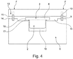
- FIG. 4 illustrates the interaction of the first mold 8 with the second mold 10 for the injection molding.
- the guide pins 9 of the first fitting 8 are guided in corresponding guide holes 13 of the second fitting 10, so that the mold can be closed by the second Fitting 10 is pressed down against the first mold piece 8 until flat opposite surfaces 14, 15 of the two fittings 8, 10 are pressed against each other.
- FIG. 4 indicates that thereby the Spritzgusskavtician 11 forms a closed space into which the material of the base part 6 is injected. It is also clear that the pressing of the second fitting 10 to the first fitting 8 until fully closing the injection mold requires that the hard component 3 is elastically compressed.
- the soft component 2 protrudes into a corresponding negative mold 16 of the first mold piece 8, which is closed at the top to the circumferential flange edge 4 out with an annular projection 17 on which the flange-like edge 4 of the hard component 3 is pressed, so that the negative mold with the Soft component therein is securely sealed during injection molding.
- the soft component 2 is therefore completely shielded by the hard component 3 from the material pressure of the material of the base part 6 in the injection molding process.
- the arrows F illustrate the closing pressure of the injection mold, with which the second fitting 10 from the in FIG. 4 not yet closed position against the first mold piece 8 is pressed until the flat surfaces 14, 15 lie on one another with pressure, whereby the tool is closed.
- the inventive construction of the cushioning molded part 1 of the soft component 2 and the hard component 3 thus allows the cushioning mold part 1 can be embedded in the material of the base part 6 in an injection molding without the injection pressure makes the soft component 2 useless.
- the hard component 3 shields the soft component 2 from the injection pressure and serves with its peripheral flange-like edge 4 of the sealing of the female mold negative mold 16, in which the soft component 2 is received.
- the flat surface 15 of the second shaped part 10 can be seen to lie flat against the flat hard component 3, so that it is connected to the material of the base part 6 substantially in the region of a circumferential narrow edge 18.
- the Spritzgusskavtician 11 may be formed with the annular projection 17 so that the flange-like edge 4 partially on its upper side (in FIG. 4 pointing downward) is encapsulated annularly, so that the circumferential flange-like edge 4 is injected into two surfaces perpendicular to each other in the material of the base part 6.
- the surface 15 of the second fitting 10 with recesses to allow material of the base part 6 to occur on a third side of the hard component 3, so that the hard component 3 can be encapsulated on three sides. It is only important that the closing pressure F of the tool sealingly presses the flange-like edge 4 of the hard component 3 against the first fitting 8 to ensure the sealing of the negative mold 16 with the soft component 2 therein during the injection molding process.
Landscapes
- Engineering & Computer Science (AREA)
- Manufacturing & Machinery (AREA)
- Mechanical Engineering (AREA)
- Injection Moulding Of Plastics Or The Like (AREA)
- Moulds For Moulding Plastics Or The Like (AREA)
Abstract
Description
- Die Erfindung betrifft ein Spritzgussteil, gebildet aus einem im Spritzgussverfahren hergestellten Basisteil und einem daran befestigten polsternden Formteil.
- Die Materialauswahl für Spritzgussteile erfolgt unter zahlreichen Aspekten, wozu insbesondere die gewünschte Stabilität, Festigkeit, Elastizität und Flexibilität des herzustellenden Spritzgussteils gehören. Unter den jeweiligen Aspekten ausgewählte Materialien können aber nicht alle Anforderungen erfüllen, insbesondere wenn das Spritzgussteil zur Anlage an einem Körper vorgesehen ist. Das Material des Spritzgussteils kann dann aufgrund von Relativbewegungen zu Scheuerstellen und ähnlichen Beschädigungen führen. Insbesondere bei der Anlage an einem lebenden menschlichen oder tierischen Körper können dabei unangenehme Druckstellen, Schürfwunden oder gar Einschnitte verursacht werden. Es ist daher bekannt, das Spritzgussteil mit einem polsternden Formteil zu versehen, das aus einem weicheren Material besteht. Hierfür eignet sich insbesondere ein Formteil aus einem Gel. Da das weiche Formteil regelmäßig den Spritzgussdrücken nicht formstabil standhalten kann, wird es üblicherweise separat hergestellt und nachträglich auf das im Spritzgussverfahren hergestellte Spritzgussteil aufgebracht, beispielsweise aufgeklebt. Dieses Verfahren ist umständlich und sorgt für eine Verteuerung des Spritzgussteils.
- Der vorliegenden Erfindung liegt die Aufgabe zugrunde, ein Spritzgussteil der genannten Art zu ermöglichen, bei dem ein separater Aufwand für die Verbindung von Basisteil und polsternden Formteil nicht benötigt wird.
- Die Lösung dieser Aufgabe gelingt bei einem Spritzgussteil der eingangs erwähnten Art dadurch, dass das polsternde Formteil mit einem weichen, gegossenen Gelkörper (Weichkomponente) gebildet ist, der auf einer Begrenzungsfläche mit einem härteren, jedoch flexiblen und elastisch verformbaren Material (Hartkomponente) vollständig abgedeckt ist, das einen seitlich über den Gelkörper herausstehenden umlaufenden flanschartigen Rand ausbildet, wobei das polsternde Formteil über die Hartkomponente mit dem Basisteil verbunden ist.
- Das erfindungsgemäße Spritzgussteil weist somit ein polsterndes Formteil auf, das zweiteilig ausgebildet ist. Die eigentliche Polsterwirkung wird durch eine Weichkomponente bewirkt, die durch einen weichen gegossenen Gelkörper gebildet ist. Zum Basisteil hin ist diese Weichkomponente vollständig abgedeckt durch eine Hartkomponente des polsternden Formteils. Die Hartkomponente weist eine größere Härte auf als die Weichkomponente, ist jedoch ebenfalls flexibel und elastisch verformbar. Die Hartkomponente ist vorzugsweise aus einem Hartgel gebildet, das in seiner Struktur ähnlich ist wie das Gel der Weichkomponente, sodass sich die Weichkomponente und die Hartkomponente im flüssigen Zustand gut miteinander materialschlüssig verbinden, ohne dass ein Klebstoff benötigt wird. Die Hartkomponente überragt den Gelkörper seitlich mit einem umlaufenden flanschartigen Rand, mit dem in der Spritzgussform die benötigte Abgrenzung des weichen gegossenen Gelkörpers gegenüber dem eingespritzten Material des Basisteils erfolgt. Der umlaufende flanschartige Rand ermöglicht eine vollständige Abdichtung des durch den gegossenen Gelkörper ausgefüllten Raums, der durch eine Negativform im Spritzwerkzeug gebildet wird. Durch die aufgebrachte Hartkomponente des polsternden Formteils ist dieses in der Lage, dem anschließenden Spritzdruck für das Basisteil formstabil zu widerstehen. Dabei wird das Material der Hartkomponente im Bereich des abdichtenden umlaufenden Randes stark komprimiert, beispielsweise auf eine Dicke von 30 % der Ausgangsdicke des Materials. Wenn also in einem bevorzugten Ausführungsbeispiel die Materialstäke des umlaufenden flanschartigen Rands 1 mm beträgt, wird dieser Rand zwischen zwei Formteilen eingeklemmt und auf beispielsweise 0,3 mm durch den Schließdruck der Spritzgießform zusammengedrückt. Das Material der Hartkomponente muss dabei so ausgewählt werden, dass es dieser elastischen Verformung und dem Spritzdruck standhalten kann. Dabei kann es zweckmäßig sein, wenn die Hartkomponente aus einem gefüllten Hartgel besteht, insbesondere einem mit einem Metalloxid oder einem Metalloidoxid, insbesondere Kieselsäure, gefüllten Hartgel, insbesondere einem gefüllten Polyurethangel, wie es durch
EP 1 125 975 B1 bekannt ist. In einem bevorzugten Ausführungsbeispiel hat das Hartgel eine Härte 40 Shore A. - Bevorzugte Materialkombinationen für die Weichkomponente und die Hartkomponente sind PU-Softgel mit PU-Hartgel sowie Silikon-Softgel mit Silikon-Hartgel. Möglich sind aber auch andere Kombinationen, beispielweise ein PU-Schaum als Weichkomponente mit einem PU-Hartgel als Hartkomponente.
- Insbesondere bei der Verwendung eines Softgels aus Polyurethan (PU), das zur Klebrigkeit neigt, ist es vorteilhaft, wenn die Weichkomponente durch eine Abdeckfolie außerhalb der von der Hartkomponente abgedeckten Begrenzungsfläche vollständig umschlossen ist. Die Abdeckfolie ist zweckmäßigerweise eine Hochleistungs-TPU-Folie, wie sie beispielsweise unter den Marken "Platilon" oder "Dureflex" vertrieben werden.
- Die Folie verbindet sich bei dem Aufbringen des Materials der Hartkomponente mit der Hartkomponente, sodass sie zusätzlich die Funktion erfüllt, die Weichkomponente auch bei Belastung in einem begrenzten Volumen zu halten, sodass die Weichkomponente nach einer Belastung in die Ausgangsform zurückkehrt. Hierfür ist es zweckmäßig, die Abdeckfolie beispielsweise durch Tiefziehen vorzuverformen.
- Da auch das Hartgel der Hartkomponente noch klebrig sein kann, ist es zweckmäßig, wenn die von der Weichkomponente abgewandte Oberfläche der Hartkomponente ebenfalls mit einer Folie abgedeckt ist. Diese Folie muss mit dem Spritzgussmaterial verträglich sein. Insbesondere kann die Abdeckfolie der Hartkomponente ebenfalls eine TPU-Folie sein, die sich von der TPU-Folie der Weichkomponente unterscheiden kann. Als Spritzgussmaterial für das Basisteil kann ebenfalls ein TPU Verwendung finden. Allerdings sind auch andere Materialien, wie Silikon, Polycarbonat usw., möglich.
- Die Herstellung des erfindungsgemäßen Spritzgussteils mit dem gegossenen polsternden Formteil erfolgt dadurch, dass zunächst die Weichkomponente des polsternden Formteils in einer geeigneten Form gegossen wird, wobei anschließend die Hartkomponente aufgebracht wird. Das Formteil wird mit seiner Weichkomponente in eine entsprechende Negativform eingebracht, die ein erstes Formstück einer Spritzgussform bildet, sodass der umlaufende Rand der Hartkomponente auf einer die Negativform abschließenden Oberfläche abdichtend aufliegt, wenn die Spritzgussform durch ein zweites Formstück geschlossen wird und den umlaufenden Rand mit dem Schließdruck der Spritzgießform einklemmt. Dann wird der Spritzgießvorgang für das Basisteil durchgeführt, wobei die Weichkomponente in der Negativform durch die Hartkomponente gegenüber dem eingespritzten Material des Basisteils abgeschirmt und die Hartkomponente mit dem Material des Basisteils umspritzt wird.
- Bei dem erfindungsgemäßen Spritzgussteil findet somit die Verbindung zwischen dem Basisteil und dem polsternden Formteil an der Hartkomponente statt, während die Weichkomponente von dem Material des Basisteils durch die Abdichtung mittels der Hartkomponente abgeschirmt bleibt. Für einige Anwendungsfälle kann es vorteilhaft sein, wenn die Verbindung zwischen der Hartkomponente und dem Material des Basisteils ausschließlich im Bereich der schmalen freien Kante der Hartkomponente des polsternden Formteils erfolgt, wenn also die von der Weichkomponente abgewandte Fläche der Hartkomponente frei bleibt.
- Zum Aufbringen der die Weichkomponente abdeckenden Folie wird diese zunächst in die Gießform für die Weichkomponente eingeformt, beispielweise durch Tiefziehen, sodass das Eingießen der Weichkomponente in die mit der Folie ausgekleidete Gießform erfolgt. Anschließend wird die Hartkomponente aufgebracht, vorzugsweise ebenfalls durch einen Gießvorgang und vorzugsweise noch während sich die Weichkomponente noch in ihrer Gießform befindet. Die Vernetzung der beiden Komponenten kann beispielsweise bei Polyurethan reaktiv erfolgen. Anschließend wird das polsternde Formteil in die Negativform der Spritzgussform eingelegt und der Spritzgießvorgang für das Basisteil durchgeführt.
- In einer Weiterbildung des erfindungsgemäßen Verfahrens wird vor dem Durchführen des Spritzgießvorgangs die von der Weichkomponente abgewandte Fläche der Hartkomponente noch mit einer Abdeckfolie abgedeckt. Dies ist insbesondere zweckmäßig, wenn die Verbindung zwischen dem polsternden Formteil und dem Basisteil, beispielsweise ausschließlich im Bereich der schmalen freien Kante der Hartkomponente des polsternden Formteils, so erfolgt, dass die von der Weichkomponente abgewandte Fläche der Hartkomponente nicht von dem Material des Basisteils abgedeckt wird und daher frei bleibt. Die Folie vermeidet dann eine möglicherweise unangenehme klebrige Oberfläche des Spritzgussteils im Bereich der Hartkomponente des polsternden Formteils. Das Aufbringen der Folie erfolgt vorzugsweise vor dem Einlegen in die Spritzgießform, insbesondere noch in der Gießform für die Weichkomponente nach dem Aufbringen, vorzugsweise Aufgießen, der Hartkomponente.
- Die Erfindung wird im Folgenden anhand von in der Zeichnung dargestellten Ausführungsbeispielen näher erläutert.
- Es zeigen:
- Figur 1
- eine Seitenansicht und eine Draufsicht eines polsternden Formteils aus einer Weichkomponente und einer Hartkomponente;
- Figur 2
- eine Seitenansicht und eine Draufsicht eines fertigen Spritzgussteils, bei dem das polsternde Formteil mit dem Material eines Basisteils verbunden ist;
- Figur 3
- eine Draufsicht auf ein erstes Formstück (Unterteil) einer Spritzgussform;
- Figur 4
- einen Schnitt durch die Spritzgussform aus erstem Formstück und zweitem Formstück (noch nicht geschlossen) mit eingelegtem polsternden Formteil, dessen Hartkomponente von dem Material des Basisteils umspritzt wird.
- Das in
Figur 1 dargestellte Ausführungsbeispiel eines polsternden Formteils 1 besteht aus einer Weichkomponente 2, die aus einem Polyurethan-Softgel gebildet sein kann und einer Hartkomponente 3, die eine Seite - hier eine Unterseite - der Weichkomponente vollständig abdeckt und über die Kontur der Weichkomponente mit einem umlaufenden, flanschartigen Rand 4 hinaussteht. Die Weichkomponente 2 ist in dem dargestellten Ausführungsbeispiel auf allen Seiten, die nicht von der Hartkomponente 3 abgedeckt sind, mit einer vorverformten Folie 5 abgedeckt. Die Folie 5 ist vorzugsweise auf dem umlaufenden flanschartigen Rand 4 der Hartkomponente 3 mit dieser verbunden, sodass die Folie 5 mit der Hartkomponente 3 einen von der Weichkomponente 2 ausgefüllten Raum einschließt. - Die Draufsicht in
Figur 1 b) verdeutlicht, dass die Weichkomponente 2 und die Hartkomponente 3 eine langgestreckte Form aufweisen können. Ersichtlich sind alle möglichen Formgebungen für die Weichkomponente 2 und die Hartkomponente 3 möglich, solange die Hartkomponente 3 die Weichkomponente 2 mit einem umlaufenden flanschartigen Rand 4 umgeben kann, dessen Funktion unten noch näher erläutert wird. -
Figur 2 zeigt eine Seitenansicht und eine Draufsicht eines Spritzgussteils, das aus dem polsternden Formteil 1 und einem Basisteil 6 besteht. Das Basisteil 6 ist hier lediglich als Ausführungsbeispiel in im Wesentlichen rechteckiger, langgestreckter Form dargestellt, kann jedoch jede beliebige Ausbildung aufweisen. Insbesondere muss das Basisteil 6 nicht zwingend flächig ausgebildet sein. Es kann auch kompliziertere Formen aufweisen, wie beispielsweise eine Brillenform für eine Augenmaske. Das Basisteil 6 kann ferner rahmenförmig ausgebildet sein, wobei das polsternde Formteil 1 einen Innenrand und/oder Außenrand des Rahmenteils abpolstern kann. In dem inFigur 2 dargestellten Ausführungsbeispiel weist das Basisteil angespritzte Rasthaken 7 auf, mit denen das Basisteil 6 und das mit ihm verbundene polsternde Formteil 1 in eine Aufnahme einschnappbar ist. - Das Basisteil 6 wird im Spritzgussverfahren hergestellt, wobei das polsternde Formteil 1 beim Spritzgussvorgang mit dem Basisteil 6 verbunden wird.
-
Figur 3 zeigt eine Draufsicht auf ein erstes Formstück 8 eines Spritzgusswerkzeugs. Das erste Formstück 8 bildet ein rechteckiges Formunterteil, das an zwei diagonal gegenüberliegenden Ecken mit Führungsbolzen 9 zur exakten Positionierung zu einem zweiten Formstück 10 (Formoberteil;Figur 4 ) versehen ist. In das inFigur 3 dargestellte erste Formstück 8 ist eine Spritzgusskavität 11 eingeformt, mit der das Basisteil 6 geformt wird. Zentral in der Spritzgusskavität 11 befindet sich das eingelegte polsternde Formteil 1, das vorzugsweise als gegossenes Formteil vorab hergestellt worden ist. -
Figur 3 lässt ferner einen Angusskanal 12 erkennen, über den die Spritzgusskavität 11 beim Spritzgießvorgang mit dem Material des Basisteils 6 gefüllt wird. -
Figur 4 verdeutlicht das Zusammenspiel des ersten Formstücks 8 mit dem zweiten Formstück 10 für den Spritzgießvorgang. Die Führungsbolzen 9 des ersten Formstücks 8 werden in entsprechenden Führungslöchern 13 des zweiten Formstücks 10 geführt, sodass die Form dadurch geschlossen werden kann, dass das zweite Formstück 10 nach unten gegen das erste Formstück 8 gedrückt wird, bis plane gegenüberliegende Flächen 14, 15 der beiden Formstücke 8, 10 aufeinander gepresst werden.Figur 4 lässt erkennen, dass dadurch die Spritzgusskavität 11 einen geschlossenen Raum bildet, in den das Material des Basisteils 6 eingespritzt wird. Dabei wird auch deutlich, dass das Andrücken des zweiten Formstücks 10 an das erste Formstück 8 bis zum vollständigen Schließen der Spritzgussform bedingt, dass die Hartkomponente 3 elastisch zusammengedrückt wird. Die Weichkomponente 2 ragt dabei in eine entsprechende Negativform 16 des ersten Formstücks 8, die an der Oberseite zum umlaufenden flanschartigen Rand 4 hin mit einem ringförmigen Vorsprung 17 abgeschlossen ist, auf den der flanschartige Rand 4 der Hartkomponente 3 aufgepresst wird, sodass die Negativform mit der darin befindlichen Weichkomponente beim Spritzgießvorgang sicher abgedichtet ist. Die Weichkomponente 2 wird daher durch die Hartkomponente 3 von dem Materialdruck des Materials des Basisteils 6 beim Spritzgießvorgang vollständig abgeschirmt. - Die Pfeile F verdeutlichen den Schließdruck des Spritzgießwerkzeugs, mit dem das zweite Formstück 10 aus der in
Figur 4 noch nicht geschlossenen Stellung gegen das erste Formstück 8 gedrückt wird, bis die planen Flächen 14, 15 mit Druck aufeinanderliegen, wodurch das Werkzeug geschlossen ist. - Die erfindungsgemäße Ausbildung des polsternden Formteils 1 aus der Weichkomponente 2 und der Hartkomponente 3 ermöglicht somit, dass das polsternde Formteil 1 in das Material des Basisteils 6 in einem Spritzgießvorgang eingebettet werden kann, ohne dass der Spritzdruck die Weichkomponente 2 unbrauchbar macht. Die Hartkomponente 3 schirmt die Weichkomponente 2 von dem Spritzdruck ab und dient mit seinem umlaufenden flanschartigen Rand 4 der Abdichtung der Negativform 16 des Spritzgusswerkzeugs, in der die Weichkomponente 2 aufgenommen wird.
- Bei einer Ausführungsform des Spritzgießwerkzeugs gemäß
Figur 4 liegt ersichtlich die plane Fläche 15 des zweiten Formstücks 10 flächig an der flächigen Hartkomponente 3 an, sodass diese mit dem Material des Basisteils 6 im Wesentlichen im Bereich einer umlaufenden schmalen Kante 18 verbunden wird. Darüber hinaus kann die Spritzgusskavität 11 mit dem ringförmigen Vorsprung 17 so ausgebildet sein, dass der flanschartige Rand 4 teilweise auch an seiner Oberseite (die inFigur 4 nach unten zeigt) ringförmig umspritzt wird, sodass der umlaufende flanschartige Rand 4 auf zwei senkrecht zueinander stehenden Flächen in das Material des Basisteils 6 eingespritzt wird. - Selbstverständlich ist es weiterhin möglich, die Fläche 15 des zweiten Formstücks 10 mit Ausnehmungen zu versehen, um Material des Basisteils 6 auch auf einer dritten Seite der Hartkomponente 3 eintreten zu lassen, sodass die Hartkomponente 3 auch auf drei Seiten umspritzt sein kann. Wichtig ist dabei lediglich, dass der Schließdruck F des Werkzeugs den flanschartigen Rand 4 der Hartkomponente 3 abdichtend gegen das erste Formstück 8 drückt, um die Abdichtung der Negativform 16 mit der darin befindlichen Weichkomponente 2 während des Spritzgussvorgangs sicherzustellen.
Claims (9)
- Spritzgussteil gebildet aus einem im Spritzgussverfahren hergestellten Basisteil (6) und einem daran befestigten polsternden Formteil (1), dadurch gekennzeichnet, dass das polsternde Formteil (1) mit einem weichen, gegossenen, eine Weichkomponente (2) bildenden Gelkörper gebildet ist, der auf seiner Begrenzungsfläche mit einem härteren, jedoch flexiblen und elastisch verformbaren, eine Hartkomponente (3) bildenden Material vollständig abgedeckt ist, das einen seitlich über die Weichkomponente (2) herausstehenden umlaufenden flanschartigen Rand (4) ausbildet, wobei das polsternde Material (1) über die Hartkomponente (3) mit dem Basisteil (6) verbunden ist, indem die Hartkomponente (3) mit dem Material des Basisteils (2) beim Spritzgießvorgang für das Basisteil umspritzt wird.
- Spritzgussteil nach Anspruch 1, dadurch gekennzeichnet, dass die Weichkomponente (2) durch eine Abdeckfolie (5) außerhalb der von der Hartkomponente (3) abgedeckten Begrenzungsfläche vollständig umschlossen ist.
- Spritzgussteil nach Anspruch 1 oder 2, dadurch gekennzeichnet, dass die Hartkomponente (3) flächig mit einer konstanten Materialstärke ausgebildet ist.
- Spritzgussteil nach einem der Ansprüche 1 bis 3, dadurch gekennzeichnet, dass die Hartkomponente (3) als Gel ausgebildet ist.
- Spritzgussteil nach Anspruch 4, dadurch gekennzeichnet, dass die Hartkomponente (3) ein mit pyrogener Kieselsäure gefülltes Polyurethangel ist.
- Spritzgussteil nach einem der Ansprüche 1 bis 5, dadurch gekennzeichnet, dass die von der Weichkomponente (2) abgewandte Fläche der Hartkomponente (3) mit einer Folie abgedeckt ist.
- Verfahren zur Herstellung eines Spritzgussteils nach einem der Ansprüche 1 bis 6 mit den Verfahrensschrittena) Einbringen des polsternden Formteils (1) mit der Weichkomponente (2) in eine entsprechende Negativform (16), die sich in einem ersten Formstück (8) einer Spritzgussform befindet, sodass der umlaufende Rand (4) der Hartkomponente (3) auf einer die Negativform (16) abschließenden Oberfläche abdichtend aufliegt, wenn die Spritzgussform durch ein zweites Formstück (10) geschlossen wird,b) Durchführung eines Spritzgießvorgangs für das Basisteil (6), wobei die Weichkomponente (2) in der Negativform (16) durch die Hartkomponente (3) gegenüber dem eingespritzten Material des Basisteils (6) abgeschirmt und die Hartkomponente (3) mit dem Material des Basisteils (6) umspritzt wird.
- Verfahren nach Anspruch 7, dadurch gekennzeichnet, dass die Weichkomponente (2) in eine mit einer Folie (5) ausgekleidete Gießform gegossen wird und dass die Folie beim anschließenden Aufbringen der Hartkomponente (3) mit dieser verbunden wird.
- Verfahren nach Anspruch 7 oder 8, dadurch gekennzeichnet, dass vor der Durchführung des Spritzgießvorgangs auf die freie, von der Weichkomponente (2) abgewandte Fläche der Hartkomponente (3) eine Abdeckfolie aufgelegt wird.
Applications Claiming Priority (1)
| Application Number | Priority Date | Filing Date | Title |
|---|---|---|---|
| DE102015205645.7A DE102015205645B4 (de) | 2015-03-27 | 2015-03-27 | Spritzgussteil mit einem Basisteil und einem daran befestigten polsternden Formteil und Verfahren zu seiner Herstellung |
Publications (2)
| Publication Number | Publication Date |
|---|---|
| EP3072663A1 true EP3072663A1 (de) | 2016-09-28 |
| EP3072663B1 EP3072663B1 (de) | 2019-02-27 |
Family
ID=55262744
Family Applications (1)
| Application Number | Title | Priority Date | Filing Date |
|---|---|---|---|
| EP16153188.4A Active EP3072663B1 (de) | 2015-03-27 | 2016-01-28 | Spritzgussteil mit einem basisteil und einem daran befestigten polsternden formteil und verfahren zu seiner herstellung |
Country Status (5)
| Country | Link |
|---|---|
| US (1) | US10464279B2 (de) |
| EP (1) | EP3072663B1 (de) |
| JP (1) | JP2016187958A (de) |
| CN (1) | CN106003555A (de) |
| DE (1) | DE102015205645B4 (de) |
Families Citing this family (2)
| Publication number | Priority date | Publication date | Assignee | Title |
|---|---|---|---|---|
| US20180325206A1 (en) * | 2017-05-10 | 2018-11-15 | Carleton Technologies, Inc. | Custom fit mask and strap assembly and method of producing a custom fit mask and strap assembly |
| CN108544710A (zh) * | 2018-04-27 | 2018-09-18 | 业成科技(成都)有限公司 | 触控面板、其制作方法及该制作方法中使用的模具 |
Citations (7)
| Publication number | Priority date | Publication date | Assignee | Title |
|---|---|---|---|---|
| DE3712882A1 (de) * | 1987-04-15 | 1988-11-03 | Schaeffler Teppichboden Gmbh | Auskleidungsformteil und verfahren zu dessen herstellung |
| EP0552040A1 (de) * | 1992-01-15 | 1993-07-21 | Patrick Arthur Leach | Verfahren und Vorrichtung zur Herstellung eines Lautsprecherkonus und einer Sickenanordnung |
| US20030169236A1 (en) * | 2000-07-14 | 2003-09-11 | John Crocker | Hand and wrist support |
| EP1125975B1 (de) | 2000-02-08 | 2004-09-08 | TechnoGel GmbH & Co. KG | Gelmassen auf Basis von Reaktionsprodukten aus Polyolen und Polyisocyanaten |
| DE102006013857A1 (de) * | 2006-03-23 | 2007-09-27 | Ise Intex Gmbh | Dekoriertes Kunststoffformteil mit einer teilweisen Polsterung und Verfahren zur Herstellung |
| US20090287283A1 (en) * | 2008-05-16 | 2009-11-19 | Seth Biser | Thermal compress assembly and system with external frame |
| WO2014055596A1 (en) * | 2012-10-02 | 2014-04-10 | Basf Se | Jounce bumper |
Family Cites Families (34)
| Publication number | Priority date | Publication date | Assignee | Title |
|---|---|---|---|---|
| GB1541071A (en) * | 1977-08-10 | 1979-02-21 | Fyfe Carnegie Ltd | Cushions and mattresses |
| JPS60201930A (ja) * | 1984-03-26 | 1985-10-12 | Honda Motor Co Ltd | 樹脂成形品の製造方法 |
| GB2161375A (en) * | 1984-07-09 | 1986-01-15 | Milsco Mfg Co | Composite foam-seat cushion and method of preparation |
| US4999068A (en) * | 1986-02-24 | 1991-03-12 | Chiarella Michele A | Method for making an anatomical multilayer bicycle-type seat |
| JPH05162167A (ja) * | 1991-12-13 | 1993-06-29 | Kasai Kogyo Co Ltd | 自動車用ドアトリムにおける緩衝用パッドの固定方法 |
| US5445858A (en) * | 1993-06-11 | 1995-08-29 | Nwoko; Luck I. | Attenuating pad |
| JPH1015959A (ja) * | 1996-06-28 | 1998-01-20 | Mitsuboshi Belting Ltd | 衝撃緩和と応力分散性を備えたシート材とその製造方法 |
| US6129695A (en) * | 1996-12-18 | 2000-10-10 | Peters; Rick | Athletic brace |
| DE60026511T2 (de) * | 1999-02-05 | 2006-11-09 | Ex One Corp. | Energie absorbierendes medium verwendendes intelligentes polstersystem und daraus herstellbare artikel |
| US6503161B2 (en) * | 1999-02-11 | 2003-01-07 | Brett Peter Bothwell | Game racket including a string suspension system |
| US6966155B2 (en) * | 2004-03-29 | 2005-11-22 | Nevison Dale C H | Mat perimeter system |
| US7449228B2 (en) * | 2004-07-26 | 2008-11-11 | Shirley Mason | Floor mat |
| ITVI20050231A1 (it) * | 2005-08-12 | 2007-02-13 | Selle Royal Spa | Metodo per la realizzazione di supporti elastici integrali, nonche' supporti elastici integrali ottenibili con tale metodo |
| WO2007076477A2 (en) * | 2005-12-23 | 2007-07-05 | Polyworks, Inc. | Handle with soft gel cushioning member |
| WO2007100922A2 (en) * | 2006-02-28 | 2007-09-07 | Polyworks, Inc. | Methods of making polymeric articles and polymeric articles formed thereby |
| US7682680B2 (en) * | 2006-09-30 | 2010-03-23 | Let's Gel, Inc. | Method and apparatus for fabricating an anti-fatigue mat employing multiple durometer layers |
| JP4941032B2 (ja) * | 2007-03-19 | 2012-05-30 | ソニー株式会社 | 吸盤およびその製造方法 |
| WO2008128206A1 (en) * | 2007-04-13 | 2008-10-23 | Polyworks, Inc. | Cushioning medallions, methods of making and methods of using |
| WO2009063332A2 (en) * | 2007-10-24 | 2009-05-22 | Herfried Lammer | System and method of using shear thickening materials in sports products |
| US9603461B2 (en) * | 2008-10-03 | 2017-03-28 | Edizone, Llc | Breathable gel |
| JP5568231B2 (ja) | 2008-11-07 | 2014-08-06 | 日本ゴア株式会社 | 成形品の製造方法 |
| US20100237082A1 (en) * | 2009-03-20 | 2010-09-23 | Products Of Tomorrow, Inc. | Gel cushion mat |
| CN102026508B (zh) * | 2010-12-29 | 2013-12-11 | 鸿富锦精密工业(深圳)有限公司 | 壳体及其制造方法 |
| US20120167308A1 (en) * | 2010-12-29 | 2012-07-05 | James Van Lear | Composite Gel and Foam Support Pad and Method for Manufacturing Same |
| US20130020229A1 (en) * | 2011-07-18 | 2013-01-24 | G-Form, LLC | Configurable protective cover, method of making and method of using |
| US9615611B2 (en) * | 2011-08-11 | 2017-04-11 | G-Form, LLC | Breathable impact absorbing cushioning and constructions |
| US20130084413A1 (en) * | 2011-10-04 | 2013-04-04 | Let's Gel Incorporated | Anti-fatigue mat with removable resilient cushioning member |
| US8828301B2 (en) * | 2011-10-18 | 2014-09-09 | The Standard Register Company | In-mold labeling systems with polymeric label receptor and in-mold labeling methods therewith |
| US9238540B2 (en) * | 2011-10-20 | 2016-01-19 | G-Form, LLC | Protective edge inserts and cases including such inserts |
| US20130171419A1 (en) * | 2011-11-04 | 2013-07-04 | Winfield Consumer Products, Inc. | Flexible custom floor mats |
| US20140096324A1 (en) * | 2012-03-13 | 2014-04-10 | Polyworks, Inc. | Composite material, method of making and articles formed thereby |
| ITVR20130084A1 (it) * | 2013-04-08 | 2014-10-09 | Technogel Italia Srl | Elemento di imbottitura per sedute e metodo per la sua realizzazione |
| CN203831724U (zh) | 2014-02-24 | 2014-09-17 | 市光法雷奥(佛山)汽车照明系统有限公司 | 二次注塑模具 |
| US9216678B1 (en) * | 2014-06-27 | 2015-12-22 | Tyanne Mobley | Heel protecting vehicle floor mat device |
-
2015
- 2015-03-27 DE DE102015205645.7A patent/DE102015205645B4/de not_active Expired - Fee Related
-
2016
- 2016-01-28 EP EP16153188.4A patent/EP3072663B1/de active Active
- 2016-02-10 JP JP2016023671A patent/JP2016187958A/ja active Pending
- 2016-03-22 US US15/077,261 patent/US10464279B2/en not_active Expired - Fee Related
- 2016-03-24 CN CN201610172255.5A patent/CN106003555A/zh active Pending
Patent Citations (7)
| Publication number | Priority date | Publication date | Assignee | Title |
|---|---|---|---|---|
| DE3712882A1 (de) * | 1987-04-15 | 1988-11-03 | Schaeffler Teppichboden Gmbh | Auskleidungsformteil und verfahren zu dessen herstellung |
| EP0552040A1 (de) * | 1992-01-15 | 1993-07-21 | Patrick Arthur Leach | Verfahren und Vorrichtung zur Herstellung eines Lautsprecherkonus und einer Sickenanordnung |
| EP1125975B1 (de) | 2000-02-08 | 2004-09-08 | TechnoGel GmbH & Co. KG | Gelmassen auf Basis von Reaktionsprodukten aus Polyolen und Polyisocyanaten |
| US20030169236A1 (en) * | 2000-07-14 | 2003-09-11 | John Crocker | Hand and wrist support |
| DE102006013857A1 (de) * | 2006-03-23 | 2007-09-27 | Ise Intex Gmbh | Dekoriertes Kunststoffformteil mit einer teilweisen Polsterung und Verfahren zur Herstellung |
| US20090287283A1 (en) * | 2008-05-16 | 2009-11-19 | Seth Biser | Thermal compress assembly and system with external frame |
| WO2014055596A1 (en) * | 2012-10-02 | 2014-04-10 | Basf Se | Jounce bumper |
Also Published As
| Publication number | Publication date |
|---|---|
| DE102015205645B4 (de) | 2018-02-15 |
| JP2016187958A (ja) | 2016-11-04 |
| EP3072663B1 (de) | 2019-02-27 |
| CN106003555A (zh) | 2016-10-12 |
| DE102015205645A1 (de) | 2016-09-29 |
| US10464279B2 (en) | 2019-11-05 |
| US20160279845A1 (en) | 2016-09-29 |
Similar Documents
| Publication | Publication Date | Title |
|---|---|---|
| DE102004021222B4 (de) | Hartes oder weiches Verbund-Paneel mit Schaumschicht | |
| DE102009024245B4 (de) | Verfahren zur Herstellung eines Patienteninterfaces mit Gelfüllung sowie Patienteninterface mit Gelfüllung | |
| DE102010052783A1 (de) | Verfahren zur Herstellung eines Schuhs und Schuh | |
| DE102012110419A1 (de) | Vorrichtung und verfahren zum herstellen eines crash-pads | |
| DE3031223A1 (de) | Brustprothese und verfahren zu ihrer herstellung | |
| DE102014108687A1 (de) | Vorrichtung zum Spritzen einer Zwei-Farbton-Innenverkleidung | |
| EP3072663B1 (de) | Spritzgussteil mit einem basisteil und einem daran befestigten polsternden formteil und verfahren zu seiner herstellung | |
| DE102012203012B4 (de) | Verfahren zur Herstellung eines Fahrzeuginnenverkleidungsteils sowie Fahrzeuginnenverkleidungsteil | |
| DE102015114238A1 (de) | Anbindungssystem und Verfahren zur Befestigung eines Bauteils an einer Fahrzeugkarosserie | |
| EP3183110A1 (de) | Verfahren zur herstellung einer dichtung an einem bauteil sowie formgebendes werkzeug zur verwendung in einem derartigen verfahren | |
| DE1685383C3 (de) | Verfahren und Vorrichtung zum Herstellen einer Sohle aus Gummi mit Porenstruktur | |
| DE1604736A1 (de) | Verfahren zum Verbinden von Teilen aus Kunststoff | |
| DE2705548C2 (de) | Vorrichtung zur Verstärkung eines im wesentlichen aus einer thermogeformten Schale bestehenden Hohlkörpers | |
| WO2007036577A1 (de) | Verfahren zur herstellung eines kunststoffformteils mit einem integrierten fensterelement mittels spritzguss sowie spritzgegossenes kunststoffformteil mit einem integrierten fensterelement | |
| DE3840738C2 (de) | Verfahren zur Herstellung einer Dichtung | |
| DE2726141A1 (de) | Schaumpolsterkoerper, insbesondere kopfpolster fuer kraftfahrzeug-kopfstuetzen sowie vorrichtung zur herstellung desselben | |
| DE102024123990A1 (de) | Formen mit abdichtbaren Säulenstücken und Verfahren zur Herstellung von Produkten mit diesen Formen | |
| DE102009060933A1 (de) | Integrales Dämpf- und Stützelement | |
| DE2263584B2 (de) | Verfahren zum Herstellen von zweiteiligen Gießformen für die Erzeugung von geschäumten Kunststoff-Formkörpern | |
| DE1231304B (de) | Verfahren zur Herstellung von Ohrpassstuecken fuer Schwerhoerigen-Geraete und Plastik zur Durch-fuehrung des Verfahrens | |
| DE102005034143A1 (de) | Gesichtsaufstandsstruktur, insbesondere Stirnpolster für eine Atemmaskeneinrichtung | |
| DE3436934C1 (de) | Verfahren und Vorrichtung zur Herstellung einer Hohlladung | |
| DE102013205381B4 (de) | Verfahren zur Herstellung eines Faserverbundbauteils mit Anbauelement | |
| DE202021101581U1 (de) | Dichtungselement für eine Pulversintern-Vorrichtung | |
| DE102016123021B4 (de) | Vorrichtung und Verfahren zum Bearbeiten eines plattenförmigen Deckels für ein Kraftfahrzeug |
Legal Events
| Date | Code | Title | Description |
|---|---|---|---|
| PUAI | Public reference made under article 153(3) epc to a published international application that has entered the european phase |
Free format text: ORIGINAL CODE: 0009012 |
|
| AK | Designated contracting states |
Kind code of ref document: A1 Designated state(s): AL AT BE BG CH CY CZ DE DK EE ES FI FR GB GR HR HU IE IS IT LI LT LU LV MC MK MT NL NO PL PT RO RS SE SI SK SM TR |
|
| AX | Request for extension of the european patent |
Extension state: BA ME |
|
| STAA | Information on the status of an ep patent application or granted ep patent |
Free format text: STATUS: REQUEST FOR EXAMINATION WAS MADE |
|
| 17P | Request for examination filed |
Effective date: 20170310 |
|
| RBV | Designated contracting states (corrected) |
Designated state(s): AL AT BE BG CH CY CZ DE DK EE ES FI FR GB GR HR HU IE IS IT LI LT LU LV MC MK MT NL NO PL PT RO RS SE SI SK SM TR |
|
| GRAP | Despatch of communication of intention to grant a patent |
Free format text: ORIGINAL CODE: EPIDOSNIGR1 |
|
| STAA | Information on the status of an ep patent application or granted ep patent |
Free format text: STATUS: GRANT OF PATENT IS INTENDED |
|
| RIC1 | Information provided on ipc code assigned before grant |
Ipc: B29K 675/00 20060101ALI20181023BHEP Ipc: B29L 9/00 20060101ALI20181023BHEP Ipc: B29C 45/14 20060101AFI20181023BHEP Ipc: B29C 45/16 20060101ALI20181023BHEP |
|
| INTG | Intention to grant announced |
Effective date: 20181115 |
|
| GRAS | Grant fee paid |
Free format text: ORIGINAL CODE: EPIDOSNIGR3 |
|
| GRAA | (expected) grant |
Free format text: ORIGINAL CODE: 0009210 |
|
| STAA | Information on the status of an ep patent application or granted ep patent |
Free format text: STATUS: THE PATENT HAS BEEN GRANTED |
|
| RIN1 | Information on inventor provided before grant (corrected) |
Inventor name: BALLUEER, DANIEL Inventor name: KLINGEBIEL, FRANK STEFAN Inventor name: AUSMEIER, MATTHIAS Inventor name: KLINGEBIEL, JAN Inventor name: DREYLING, HANS-HERMANN |
|
| AK | Designated contracting states |
Kind code of ref document: B1 Designated state(s): AL AT BE BG CH CY CZ DE DK EE ES FI FR GB GR HR HU IE IS IT LI LT LU LV MC MK MT NL NO PL PT RO RS SE SI SK SM TR |
|
| REG | Reference to a national code |
Ref country code: GB Ref legal event code: FG4D Free format text: NOT ENGLISH |
|
| REG | Reference to a national code |
Ref country code: CH Ref legal event code: EP |
|
| REG | Reference to a national code |
Ref country code: AT Ref legal event code: REF Ref document number: 1100684 Country of ref document: AT Kind code of ref document: T Effective date: 20190315 |
|
| REG | Reference to a national code |
Ref country code: IE Ref legal event code: FG4D Free format text: LANGUAGE OF EP DOCUMENT: GERMAN |
|
| REG | Reference to a national code |
Ref country code: DE Ref legal event code: R096 Ref document number: 502016003490 Country of ref document: DE |
|
| REG | Reference to a national code |
Ref country code: NL Ref legal event code: FP |
|
| REG | Reference to a national code |
Ref country code: LT Ref legal event code: MG4D |
|
| PG25 | Lapsed in a contracting state [announced via postgrant information from national office to epo] |
Ref country code: NO Free format text: LAPSE BECAUSE OF FAILURE TO SUBMIT A TRANSLATION OF THE DESCRIPTION OR TO PAY THE FEE WITHIN THE PRESCRIBED TIME-LIMIT Effective date: 20190527 Ref country code: FI Free format text: LAPSE BECAUSE OF FAILURE TO SUBMIT A TRANSLATION OF THE DESCRIPTION OR TO PAY THE FEE WITHIN THE PRESCRIBED TIME-LIMIT Effective date: 20190227 Ref country code: LT Free format text: LAPSE BECAUSE OF FAILURE TO SUBMIT A TRANSLATION OF THE DESCRIPTION OR TO PAY THE FEE WITHIN THE PRESCRIBED TIME-LIMIT Effective date: 20190227 Ref country code: PT Free format text: LAPSE BECAUSE OF FAILURE TO SUBMIT A TRANSLATION OF THE DESCRIPTION OR TO PAY THE FEE WITHIN THE PRESCRIBED TIME-LIMIT Effective date: 20190627 Ref country code: SE Free format text: LAPSE BECAUSE OF FAILURE TO SUBMIT A TRANSLATION OF THE DESCRIPTION OR TO PAY THE FEE WITHIN THE PRESCRIBED TIME-LIMIT Effective date: 20190227 |
|
| PG25 | Lapsed in a contracting state [announced via postgrant information from national office to epo] |
Ref country code: LV Free format text: LAPSE BECAUSE OF FAILURE TO SUBMIT A TRANSLATION OF THE DESCRIPTION OR TO PAY THE FEE WITHIN THE PRESCRIBED TIME-LIMIT Effective date: 20190227 Ref country code: HR Free format text: LAPSE BECAUSE OF FAILURE TO SUBMIT A TRANSLATION OF THE DESCRIPTION OR TO PAY THE FEE WITHIN THE PRESCRIBED TIME-LIMIT Effective date: 20190227 Ref country code: RS Free format text: LAPSE BECAUSE OF FAILURE TO SUBMIT A TRANSLATION OF THE DESCRIPTION OR TO PAY THE FEE WITHIN THE PRESCRIBED TIME-LIMIT Effective date: 20190227 Ref country code: IS Free format text: LAPSE BECAUSE OF FAILURE TO SUBMIT A TRANSLATION OF THE DESCRIPTION OR TO PAY THE FEE WITHIN THE PRESCRIBED TIME-LIMIT Effective date: 20190627 Ref country code: BG Free format text: LAPSE BECAUSE OF FAILURE TO SUBMIT A TRANSLATION OF THE DESCRIPTION OR TO PAY THE FEE WITHIN THE PRESCRIBED TIME-LIMIT Effective date: 20190527 Ref country code: GR Free format text: LAPSE BECAUSE OF FAILURE TO SUBMIT A TRANSLATION OF THE DESCRIPTION OR TO PAY THE FEE WITHIN THE PRESCRIBED TIME-LIMIT Effective date: 20190528 |
|
| PG25 | Lapsed in a contracting state [announced via postgrant information from national office to epo] |
Ref country code: DK Free format text: LAPSE BECAUSE OF FAILURE TO SUBMIT A TRANSLATION OF THE DESCRIPTION OR TO PAY THE FEE WITHIN THE PRESCRIBED TIME-LIMIT Effective date: 20190227 Ref country code: AL Free format text: LAPSE BECAUSE OF FAILURE TO SUBMIT A TRANSLATION OF THE DESCRIPTION OR TO PAY THE FEE WITHIN THE PRESCRIBED TIME-LIMIT Effective date: 20190227 Ref country code: ES Free format text: LAPSE BECAUSE OF FAILURE TO SUBMIT A TRANSLATION OF THE DESCRIPTION OR TO PAY THE FEE WITHIN THE PRESCRIBED TIME-LIMIT Effective date: 20190227 Ref country code: RO Free format text: LAPSE BECAUSE OF FAILURE TO SUBMIT A TRANSLATION OF THE DESCRIPTION OR TO PAY THE FEE WITHIN THE PRESCRIBED TIME-LIMIT Effective date: 20190227 Ref country code: SK Free format text: LAPSE BECAUSE OF FAILURE TO SUBMIT A TRANSLATION OF THE DESCRIPTION OR TO PAY THE FEE WITHIN THE PRESCRIBED TIME-LIMIT Effective date: 20190227 Ref country code: CZ Free format text: LAPSE BECAUSE OF FAILURE TO SUBMIT A TRANSLATION OF THE DESCRIPTION OR TO PAY THE FEE WITHIN THE PRESCRIBED TIME-LIMIT Effective date: 20190227 Ref country code: EE Free format text: LAPSE BECAUSE OF FAILURE TO SUBMIT A TRANSLATION OF THE DESCRIPTION OR TO PAY THE FEE WITHIN THE PRESCRIBED TIME-LIMIT Effective date: 20190227 |
|
| REG | Reference to a national code |
Ref country code: DE Ref legal event code: R097 Ref document number: 502016003490 Country of ref document: DE |
|
| PG25 | Lapsed in a contracting state [announced via postgrant information from national office to epo] |
Ref country code: PL Free format text: LAPSE BECAUSE OF FAILURE TO SUBMIT A TRANSLATION OF THE DESCRIPTION OR TO PAY THE FEE WITHIN THE PRESCRIBED TIME-LIMIT Effective date: 20190227 Ref country code: SM Free format text: LAPSE BECAUSE OF FAILURE TO SUBMIT A TRANSLATION OF THE DESCRIPTION OR TO PAY THE FEE WITHIN THE PRESCRIBED TIME-LIMIT Effective date: 20190227 |
|
| PLBE | No opposition filed within time limit |
Free format text: ORIGINAL CODE: 0009261 |
|
| STAA | Information on the status of an ep patent application or granted ep patent |
Free format text: STATUS: NO OPPOSITION FILED WITHIN TIME LIMIT |
|
| 26N | No opposition filed |
Effective date: 20191128 |
|
| PG25 | Lapsed in a contracting state [announced via postgrant information from national office to epo] |
Ref country code: SI Free format text: LAPSE BECAUSE OF FAILURE TO SUBMIT A TRANSLATION OF THE DESCRIPTION OR TO PAY THE FEE WITHIN THE PRESCRIBED TIME-LIMIT Effective date: 20190227 |
|
| PG25 | Lapsed in a contracting state [announced via postgrant information from national office to epo] |
Ref country code: TR Free format text: LAPSE BECAUSE OF FAILURE TO SUBMIT A TRANSLATION OF THE DESCRIPTION OR TO PAY THE FEE WITHIN THE PRESCRIBED TIME-LIMIT Effective date: 20190227 |
|
| PG25 | Lapsed in a contracting state [announced via postgrant information from national office to epo] |
Ref country code: MC Free format text: LAPSE BECAUSE OF FAILURE TO SUBMIT A TRANSLATION OF THE DESCRIPTION OR TO PAY THE FEE WITHIN THE PRESCRIBED TIME-LIMIT Effective date: 20190227 |
|
| REG | Reference to a national code |
Ref country code: CH Ref legal event code: PL |
|
| GBPC | Gb: european patent ceased through non-payment of renewal fee |
Effective date: 20200128 |
|
| PG25 | Lapsed in a contracting state [announced via postgrant information from national office to epo] |
Ref country code: FR Free format text: LAPSE BECAUSE OF NON-PAYMENT OF DUE FEES Effective date: 20200131 Ref country code: GB Free format text: LAPSE BECAUSE OF NON-PAYMENT OF DUE FEES Effective date: 20200128 Ref country code: LU Free format text: LAPSE BECAUSE OF NON-PAYMENT OF DUE FEES Effective date: 20200128 |
|
| PG25 | Lapsed in a contracting state [announced via postgrant information from national office to epo] |
Ref country code: LI Free format text: LAPSE BECAUSE OF NON-PAYMENT OF DUE FEES Effective date: 20200131 Ref country code: CH Free format text: LAPSE BECAUSE OF NON-PAYMENT OF DUE FEES Effective date: 20200131 |
|
| PG25 | Lapsed in a contracting state [announced via postgrant information from national office to epo] |
Ref country code: IE Free format text: LAPSE BECAUSE OF NON-PAYMENT OF DUE FEES Effective date: 20200128 |
|
| REG | Reference to a national code |
Ref country code: AT Ref legal event code: MM01 Ref document number: 1100684 Country of ref document: AT Kind code of ref document: T Effective date: 20210128 |
|
| PG25 | Lapsed in a contracting state [announced via postgrant information from national office to epo] |
Ref country code: AT Free format text: LAPSE BECAUSE OF NON-PAYMENT OF DUE FEES Effective date: 20210128 |
|
| PG25 | Lapsed in a contracting state [announced via postgrant information from national office to epo] |
Ref country code: MT Free format text: LAPSE BECAUSE OF FAILURE TO SUBMIT A TRANSLATION OF THE DESCRIPTION OR TO PAY THE FEE WITHIN THE PRESCRIBED TIME-LIMIT Effective date: 20190227 Ref country code: CY Free format text: LAPSE BECAUSE OF FAILURE TO SUBMIT A TRANSLATION OF THE DESCRIPTION OR TO PAY THE FEE WITHIN THE PRESCRIBED TIME-LIMIT Effective date: 20190227 |
|
| PG25 | Lapsed in a contracting state [announced via postgrant information from national office to epo] |
Ref country code: MK Free format text: LAPSE BECAUSE OF FAILURE TO SUBMIT A TRANSLATION OF THE DESCRIPTION OR TO PAY THE FEE WITHIN THE PRESCRIBED TIME-LIMIT Effective date: 20190227 |
|
| REG | Reference to a national code |
Ref country code: DE Ref legal event code: R082 Ref document number: 502016003490 Country of ref document: DE Representative=s name: MEISSNER BOLTE PATENTANWAELTE RECHTSANWAELTE P, DE |
|
| PGFP | Annual fee paid to national office [announced via postgrant information from national office to epo] |
Ref country code: NL Payment date: 20240123 Year of fee payment: 9 |
|
| PGFP | Annual fee paid to national office [announced via postgrant information from national office to epo] |
Ref country code: IT Payment date: 20240131 Year of fee payment: 9 Ref country code: BE Payment date: 20240122 Year of fee payment: 9 |
|
| PGFP | Annual fee paid to national office [announced via postgrant information from national office to epo] |
Ref country code: DE Payment date: 20250130 Year of fee payment: 10 |
|
| REG | Reference to a national code |
Ref country code: NL Ref legal event code: MM Effective date: 20250201 |
|
| PG25 | Lapsed in a contracting state [announced via postgrant information from national office to epo] |
Ref country code: NL Free format text: LAPSE BECAUSE OF NON-PAYMENT OF DUE FEES Effective date: 20250201 |
|
| PG25 | Lapsed in a contracting state [announced via postgrant information from national office to epo] |
Ref country code: BE Free format text: LAPSE BECAUSE OF NON-PAYMENT OF DUE FEES Effective date: 20250131 |
|
| REG | Reference to a national code |
Ref country code: BE Ref legal event code: MM Effective date: 20250131 |
|
| PG25 | Lapsed in a contracting state [announced via postgrant information from national office to epo] |
Ref country code: IT Free format text: LAPSE BECAUSE OF NON-PAYMENT OF DUE FEES Effective date: 20250128 |