EP3071805B1 - Hydraulischer ventiltrieb eines verbrennungsmotors - Google Patents
Hydraulischer ventiltrieb eines verbrennungsmotors Download PDFInfo
- Publication number
- EP3071805B1 EP3071805B1 EP14793777.5A EP14793777A EP3071805B1 EP 3071805 B1 EP3071805 B1 EP 3071805B1 EP 14793777 A EP14793777 A EP 14793777A EP 3071805 B1 EP3071805 B1 EP 3071805B1
- Authority
- EP
- European Patent Office
- Prior art keywords
- piston
- valve
- housing
- brake
- hydraulic
- Prior art date
- Legal status (The legal status is an assumption and is not a legal conclusion. Google has not performed a legal analysis and makes no representation as to the accuracy of the status listed.)
- Active
Links
- 238000002485 combustion reaction Methods 0.000 title claims description 13
- 125000006850 spacer group Chemical group 0.000 claims description 30
- 238000005259 measurement Methods 0.000 claims description 12
- 230000033001 locomotion Effects 0.000 claims description 11
- 238000000034 method Methods 0.000 claims description 5
- 230000002123 temporal effect Effects 0.000 claims description 3
- 238000012360 testing method Methods 0.000 claims description 3
- 239000012530 fluid Substances 0.000 description 3
- 230000006835 compression Effects 0.000 description 2
- 238000007906 compression Methods 0.000 description 2
- 230000000694 effects Effects 0.000 description 2
- 230000000670 limiting effect Effects 0.000 description 2
- 230000036961 partial effect Effects 0.000 description 2
- 230000002829 reductive effect Effects 0.000 description 2
- 239000011324 bead Substances 0.000 description 1
- 230000005540 biological transmission Effects 0.000 description 1
- 230000003247 decreasing effect Effects 0.000 description 1
- 230000001419 dependent effect Effects 0.000 description 1
- 238000010586 diagram Methods 0.000 description 1
- 238000006073 displacement reaction Methods 0.000 description 1
- 239000000314 lubricant Substances 0.000 description 1
- 238000003754 machining Methods 0.000 description 1
- 238000004519 manufacturing process Methods 0.000 description 1
- 230000002093 peripheral effect Effects 0.000 description 1
- 230000000284 resting effect Effects 0.000 description 1
- 238000004904 shortening Methods 0.000 description 1
- 239000007787 solid Substances 0.000 description 1
Images



Classifications
-
- F—MECHANICAL ENGINEERING; LIGHTING; HEATING; WEAPONS; BLASTING
- F01—MACHINES OR ENGINES IN GENERAL; ENGINE PLANTS IN GENERAL; STEAM ENGINES
- F01L—CYCLICALLY OPERATING VALVES FOR MACHINES OR ENGINES
- F01L1/00—Valve-gear or valve arrangements, e.g. lift-valve gear
- F01L1/12—Transmitting gear between valve drive and valve
- F01L1/14—Tappets; Push rods
- F01L1/16—Silencing impact; Reducing wear
-
- F—MECHANICAL ENGINEERING; LIGHTING; HEATING; WEAPONS; BLASTING
- F01—MACHINES OR ENGINES IN GENERAL; ENGINE PLANTS IN GENERAL; STEAM ENGINES
- F01L—CYCLICALLY OPERATING VALVES FOR MACHINES OR ENGINES
- F01L9/00—Valve-gear or valve arrangements actuated non-mechanically
- F01L9/10—Valve-gear or valve arrangements actuated non-mechanically by fluid means, e.g. hydraulic
- F01L9/11—Valve-gear or valve arrangements actuated non-mechanically by fluid means, e.g. hydraulic in which the action of a cam is being transmitted to a valve by a liquid column
- F01L9/12—Valve-gear or valve arrangements actuated non-mechanically by fluid means, e.g. hydraulic in which the action of a cam is being transmitted to a valve by a liquid column with a liquid chamber between a piston actuated by a cam and a piston acting on a valve stem
- F01L9/14—Valve-gear or valve arrangements actuated non-mechanically by fluid means, e.g. hydraulic in which the action of a cam is being transmitted to a valve by a liquid column with a liquid chamber between a piston actuated by a cam and a piston acting on a valve stem the volume of the chamber being variable, e.g. for varying the lift or the timing of a valve
-
- F—MECHANICAL ENGINEERING; LIGHTING; HEATING; WEAPONS; BLASTING
- F01—MACHINES OR ENGINES IN GENERAL; ENGINE PLANTS IN GENERAL; STEAM ENGINES
- F01L—CYCLICALLY OPERATING VALVES FOR MACHINES OR ENGINES
- F01L1/00—Valve-gear or valve arrangements, e.g. lift-valve gear
- F01L1/20—Adjusting or compensating clearance
- F01L1/205—Adjusting or compensating clearance by means of shims or the like
-
- F—MECHANICAL ENGINEERING; LIGHTING; HEATING; WEAPONS; BLASTING
- F01—MACHINES OR ENGINES IN GENERAL; ENGINE PLANTS IN GENERAL; STEAM ENGINES
- F01L—CYCLICALLY OPERATING VALVES FOR MACHINES OR ENGINES
- F01L9/00—Valve-gear or valve arrangements actuated non-mechanically
- F01L9/10—Valve-gear or valve arrangements actuated non-mechanically by fluid means, e.g. hydraulic
-
- F—MECHANICAL ENGINEERING; LIGHTING; HEATING; WEAPONS; BLASTING
- F01—MACHINES OR ENGINES IN GENERAL; ENGINE PLANTS IN GENERAL; STEAM ENGINES
- F01L—CYCLICALLY OPERATING VALVES FOR MACHINES OR ENGINES
- F01L9/00—Valve-gear or valve arrangements actuated non-mechanically
- F01L9/10—Valve-gear or valve arrangements actuated non-mechanically by fluid means, e.g. hydraulic
- F01L9/11—Valve-gear or valve arrangements actuated non-mechanically by fluid means, e.g. hydraulic in which the action of a cam is being transmitted to a valve by a liquid column
- F01L9/12—Valve-gear or valve arrangements actuated non-mechanically by fluid means, e.g. hydraulic in which the action of a cam is being transmitted to a valve by a liquid column with a liquid chamber between a piston actuated by a cam and a piston acting on a valve stem
Definitions
- the invention relates to a hydraulic valve brake for a hydraulically variable valve train of an internal combustion engine.
- the hydraulic valve brake comprises a housing having a housing wall and a housing bottom, a piston extending axially in the housing, whose one end side bounds a hydraulic pressure chamber with the housing wall and the housing bottom and whose other end actuates a gas exchange valve, wherein the housing wall in the region of the pressure chamber of a or several overflow openings is interspersed, the opening cross-sections are controlled by a pressure chamber side end limiting the control edge of the piston.
- the invention also relates to an internal combustion engine with a hydraulic valve train having such a hydraulic valve brake.
- Hydraulic valve trains which operate according to the lost-motion principle and in which between the drive side, usually the cam of a camshaft, and the output side, ie the gas exchange valve, a so-called hydraulic linkage with variable Ab Kunststoffbarem hydraulic volume, is a hydraulic valve brake that controls the touchdown speed of the closing gas exchange valve independently of the cam position and limits it to preset values that are acoustically and mechanically acceptable.
- Hydraulic valve trains, each with generic hydraulic valve brake are for example from the US 6,550,433 B2 and from the EP 0 507 521 A1 known.
- the decreasing with closing gas exchange valve pressure chamber via one or more overflow openings which extend laterally of the piston in the housing wall and the opening cross sections of a pressure chamber side control edge of the retracting into the housing piston increasingly reduced and optionally completely closed.
- the present invention has for its object to provide with simple structural means Vorrausgueen for an improved performance of an internal combustion engine with hydraulic valve train and a hydraulic valve brake of the type mentioned.
- This object is achieved in that the axial distance of the control edge of the retracted completely in the housing piston is adjusted to the housing bottom by means of a spacer of predetermined thickness.
- This setting significantly reduces and ideally eliminates the effects of component tolerances that significantly affect the brake characteristics of the valve brake. Because shortly before the placing of the gas exchange valve whose delay curve at constant hydraulic fluid viscosity is highly dependent on the course of coverage of the controlled by the piston control edge opening cross-sections in the housing wall.
- Valve brakes set in accordance with the invention are suitable not only for valve trains with (automatic) hydraulic valve clearance compensation, but also for valve drives with (manual) mechanical valve clearance compensation, in which case large motors with hydraulically variable valve train are in focus in the latter case.
- the overlap profile of the piston control edge and opening cross-section (s) merely has an offset around the (uniformly set) valve clearance. Because in this case, the piston and the decisive for the axial distance housing bottom are spaced around the valve clearance when the gas exchange valve closes.
- the adjustment of the axial distance between the piston control edge and the housing bottom can be done in various ways.
- a setting is provided in discrete thickness graduations of the spacer, wherein the respective thickness is predetermined as a result of a previous test or measurement of the deceleration curve of the unadjusted valve brake and, accordingly, the spacer is removed from a group sorting and paired with the valve brake.
- the spacer can then be joined either firmly to the housing or fixed to the piston.
- the spacer causes in the path-time course of the retracting into the valve brake piston, that the cross sections of the overflow openings are covered only with a larger piston travel of the piston control edge. As a result, the valve brake is, so to speak, "faster".
- spacer is not necessarily limited to a single part, but may also include a group of two or more parts, which are then summed up as a stack of the predetermined thickness. Due to the variety of possible combinations, the group sorting can be limited to a few individual thicknesses and, in the limiting case, to a single thickness in this case.
- the spacer may be integrally formed as a non-separate part as a projection of the piston on the pressure chamber side end face or as a projection of the housing on the housing bottom.
- the axial distance can then be adjusted by machining the projection thickness.
- the variability of the valve lift is generated by the fact that the high-pressure chamber 8 between the master piston 5 and the slave piston 6 'acts as a so-called hydraulic linkage, which - neglecting leakage - proportional to the stroke of the cam 4 displaced by the master piston hydraulic volume as a function of the opening time and the opening duration of the hydraulic valve 7 in a first, the slave piston acting on partial volume and in a second, in the medium pressure chamber 9 including piston accumulator 10 and in the low-pressure chamber 12 outflowing partial volume is split.
- the slave piston 6 ' is equipped with a hydraulic valve brake 14', which reduces the decoupling of the movement of the cam 4 Aufsetz Eck the closing gas exchange valve 2 to a mechanically and acoustically acceptable level.
- the valve brake is a throttle gap, which is formed during the final closing phase of the gas exchange valve by the overlap of a cylindrical projection 15 on the pressure chamber side end face of the slave piston with an overflow 16 which extends concentrically to the slave piston housing wall 17 '.
- FIG. 2 shows the slave side of a hydraulic variable valve train of a large engine, the gas exchange valves 2 are actuated via rocker arm 18 with mechanical valve clearance compensation.
- the highly schematic representation is with respect to the valve train on the hydraulic valve brake 14 with housing 19 and slave piston, hereinafter referred to as piston 6, reduced.
- the hollow-cylindrical housing with a housing wall 17 and a housing bottom 20 serves to guide the piston traveling axially therein, one end of which with the housing wall and the housing bottom defining a hydraulic pressure chamber 21.
- the other end of the piston actuates the gas exchange valve 2 by means of the mechanical valve clearance compensation device in the form of a valve clearance adjustment screw 22 in the rocker arm.
- overflow openings 23 and 24 via which the pressure chamber 21 communicates with the sensor-side hydraulic system, not shown here (see FIG FIG. 1 ).
- the overflow opening 23 serves with a relatively large opening cross-section as the main flow opening, via which, when the piston 6 moves in and out, the lowest possible volume flow reaches and leaves the pressure chamber.
- the overflow opening 24 forms with a relatively small opening cross-section a throttle flow opening through which the pressure chamber in the final closing phase of the gas exchange valve 2 can relieve only under significant delay of the retracting piston.
- the control of the opening cross-sections via a control edge 25 of the piston, which is formed in the simplified representation by the peripheral edge between the outer surface of the piston and the pressure chamber side end face.
- the illustration shows the piston 6 in fully retracted position in the housing 19, in which the piston is during the valve clearance adjustment to the valve clearance L measured between the adjusting screw 22 and the valve-side end face of the piston.
- the valve clearance is largely or completely shifted to the pressure chamber side end side.
- the axial distance between the piston control edge 25 and the housing bottom 20 is set according to the invention by means of a spacer 26, which influences the deceleration of the retracting into the housing piston so that all valve brakes of the internal combustion engine have substantially the same braking characteristics and that accordingly all gas exchange valves 2 of the engine with about close the same stroke course.
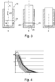
- FIGS. 3a-c show the (still) unadjusted hydraulic valve brake 14 with three different retraction positions of the piston 6 during the basic measurement of the course of movement s (t).
- the temporal stroke course of the piston acted upon by a defined force is detected until it reaches the housing bottom 20.
- the measurement result is in FIG. 4 shown very simplified on the curve with thick line width.
- the upper branch of the curve with a large gradient, ie corresponds to a comparatively high closing speed of the gas exchange valve 2 with the piston position in FIG. 3a until the pressure chamber 21 can still largely relieve unthrottled via the main flow opening 23.
- the subsequent branch of the middle gradient curve, ie with a comparatively medium closing speed corresponds to the piston position in FIG. 3b , wherein the piston control edge 25, the main flow opening already completely covered and the pressure relief mainly takes place only via the throttle flow opening 24.
- the lower curve branch with a small gradient, ie with a low closing speed, corresponds to the piston position in Figure 3c , Wherein the piston control edge completely covers both the main flow opening and the throttle flow opening and the pressure relief only via leakage gaps and ggfls. further, not shown here Drosselflußötechnisch in the housing base 20 is carried out.
- the measured curve of a relatively “slow” valve brake is more in line with one of the right reference curves, so that this valve brake is assigned a spacer with a greater thickness than a relatively “fast” valve brake, which more closely matches one of the left reference curves and their course of motion already closer to the default setting.
- FIG. 5 shows the valve brake 14 with the thus sorted and mounted spacer 26, by means of which the axial distance h between the piston control edge 25 and the housing bottom 20 is set offset by the predetermined thickness d with respect to the unconfined valve brake.
- FIGS. 7 to 9 show various views of a Auskonstru faced example of a hydraulic valve brake 14 according to the invention, respectively FIG. 2 operated by means of a rocker arm 18, a gas exchange valve 2 of a large engine with mechanical valve clearance setting.
- the screwed by means of an external thread 27 in the cylinder head 3 of the engine housing 19 of the valve brake comprises a tubular housing wall 17 and a side of the pressure chamber 21 joined housing bottom 20 which is formed by a valve seat 28 with a check valve 29 inserted therein.
- the axially displaced in the housing and secured for transport purposes by means of a snap ring 30 against complete extension piston 6 is hollow cylindrical with a gas exchange valve side end face forming piston crown 31.
- the pressure chamber-side end face of the piston is provided with a recess 32 in the form of a countersink, in which a serving as a spacer 26 shim with a predetermined thickness d is fixed by means of a longitudinal compression bandage.
- a bore 33 passing through the piston crown serves as a vent and - in the case of a leak-prone longitudinal compression bandage - as pressure relief of the piston interior.
- the housing wall 17 is penetrated by four main flow openings 23 and throttle flow openings 24 in the form of bores, via which the pressure chamber 21 - as explained above - communicates with the not shown here side hydraulic system.
- the main flow openings extend in a first transverse plane and the significantly smaller flow restrictor openings extend in a second transverse plane, which is offset from the first transverse plane in the retraction direction of the piston 6.
- the valve receptacle 28 includes an outer annular collar 34 which is inserted in a counterbore 35 of the housing wall 17 pressure medium-tight and clamped by means of the screw 27 against a shoulder 36 in the cylinder head 3, and a relative to the annular collar in the direction of the recess 32 projecting hollow cylinder section 37th
- the check valve 29 comprises a valve carrier 38 likewise inserted in the valve receptacle 28 and having a valve ball 40 spring-loaded therein against a valve seat 39. This opens in the direction of the pressure chamber 21 and controls a further overflow opening 41 via which the pressure chamber also communicates with the sensor-side hydraulic system to initialize the extension of the piston 6 when opening the gas exchange valve 2.
- shim 26 of the hydraulic medium is transferred into the pressure chamber initially via beads 42 on the annular end face 43 of the hollow cylinder portion.
- the opening cross-sections of the main and throttle flow openings 23 and 24 are controlled by the control edge 25 of the piston 6 passing over it and are in both the illustrated fully retracted piston position and in the valve clearance L set according to FIG FIG. 2 extended piston position all closed.
- the annular collar 34 is penetrated by a permanently open, further throttle flow opening 44 whose hydraulic resistance ultimately determines the touchdown speed of the gas exchange valve 2.
- the unadjusted valve brake 14 is provided with a dummy shim (not shown) of known thickness, so that in the above-described basic measurement (see FIGS. 3a-c ) the piston with the dummy shim on the ring front side and not on the Ring collar of the valve seat touches down.
- the dummy shim to be disassembled according to the basic measurement may, if necessary, be provided with a circumferential O-ring which, on the one hand, holds the dummy shim easily removable in the recess 32 and, on the other hand, seals the pressure chamber 21 with respect to the bleed bore 33.
- the axial distance h is adjusted by the thickness d of the shim 26 so that all hydraulic valve brakes 14 of the internal combustion engine have substantially the same braking characteristics and accordingly close all gas exchange valves 2 largely uniformly within a very small crank angle range.
- shims 26 are provided in the embodiment shown here with five different thicknesses in each 0.1 mm gradation.
- the spacer 26 pressed against the outer shell 45 in the inner shell 46 of the recess 32 of the piston 6.
- alternative fastenings may be provided.
- the spacer may be provided with a central bore, which is pressed on the one hand on a pin-like projection of the then solid piston or through the other a pin or screw is guided, which adds the spacer with the piston.
Landscapes
- Engineering & Computer Science (AREA)
- Mechanical Engineering (AREA)
- General Engineering & Computer Science (AREA)
- Valve Device For Special Equipments (AREA)
- Output Control And Ontrol Of Special Type Engine (AREA)
Description
- Die Erfindung betrifft eine hydraulische Ventilbremse für einen hydraulisch variablen Ventiltrieb eines Verbrennungsmotors. Die hydraulische Ventilbremse umfasst ein Gehäuse mit einer Gehäusewand und einem Gehäuseboden, einen axial im Gehäuse verfahrenden Kolben, dessen eine Stirnseite mit der Gehäusewand und dem Gehäuseboden einen hydraulischen Druckraum begrenzt und dessen andere Stirnseite ein Gaswechselventil betätigt, wobei die Gehäusewand im Bereich des Druckraums von einer oder mehreren Überströmöffnungen durchsetzt ist, deren Öffnungsquerschnitte von einer die druckraumseitige Stirnseite begrenzenden Steuerkante des Kolbens gesteuert werden.
- Die Erfindung betrifft außerdem einen Verbrennungsmotor mit einem hydraulischen Ventiltrieb, der eine derartige hydraulische Ventilbremse aufweist.
- Ein wesentlicher Bestandteil von hydraulisch variablen Ventiltrieben, die nach dem Lost-Motion-Prinzip arbeiten und bei denen zwischen der Antriebseite, in der Regel dem Nocken einer Nockenwelle, und der Abtriebseite, d.h. dem Gaswechselventil, ein sogenanntes hydraulisches Gestänge mit variabel absteuerbarem Hydraulikvolumen verläuft, ist eine hydraulische Ventilbremse, die die Aufsetzgeschwindigkeit des schließenden Gaswechselventils unabhängig von der Nockenstellung kontrolliert und auf vorgegebene Werte beschränkt, die akustisch und mechanisch akzeptabel sind. Hydraulische Ventiltriebe mit jeweils gattungsgemäßer hydraulischer Ventilbremse sind beispielsweise aus der
US 6,550,433 B2 und aus derEP 0 507 521 A1 bekannt. Bei einer derartigen Ventilbremse wird der sich mit schließendem Gaswechselventil verkleinernde Druckraum über eine oder mehrere Überströmöffnungen druckentlastet, die seitlich des Kolbens in der Gehäusewand verlaufen und deren Öffnungsquerschnitte von einer druckraumseitigen Steuerkante des in das Gehäuse einfahrenden Kolbens zunehmend reduziert und gegebenenfalls vollständig verschlossen werden. - Da die Bauteile der hydraulischen Ventilbremse wirtschaftlich nicht mit beliebig hoher Präzision herstellbar sind, verbleiben Bauteiltoleranzen, die unterschiedliche Bremscharakteristiken sogar innerhalb eines einzigen Fertigungsloses zur Folge haben. Der Ladungswechsel mit Gaswechselventilen, die in demselben Betriebspunkt mit voneinander verschiedenen Hubverläufen zu unterschiedlichen Kurbelwinkeln bezüglich der Kolbentotpunkte schließen, beeinträchtigt jedoch das Leistungs- und Emissionsverhalten des Verbrennungsmotors.
- Der vorliegenden Erfindung liegt die Aufgabe zugrunde, mit einfachen konstruktiven Mitteln Vorraussetzungen für ein verbessertes Betriebsverhalten eines Verbrennungsmotors mit hydraulischem Ventiltrieb und einer hydraulischen Ventilbremse der eingangs genannten Art zu schaffen.
- Diese Aufgabe wird dadurch gelöst, dass der Axialabstand der Steuerkante des vollständig im Gehäuse eingefahrenen Kolbens zum Gehäuseboden mittels eines Distanzstücks vorbestimmter Dicke eingestellt ist. Durch diese Einstellung werden die Auswirkungen der Bauteiltoleranzen, die die Bremscharakteristik der Ventilbremse maßgeblich beeinflussen, deutlich reduziert und idealerweise eliminiert. Denn kurz vor dem Aufsetzen des Gaswechselventils ist dessen Verzögerungsverlauf bei konstanter Hydraulikmittelviskosität in hohem Maße vom Verlauf der Überdeckung der durch die Kolbensteuerkante gesteuerten Öffnungsquerschnitte in der Gehäusewand abhängig. Der in einem Referenzpunkt, d.h. bei vollständig im Gehäuse eingefahrenem Kolben eingestellte Axialabstand zwischen der Kolbensteuerkante und dem Gehäuseboden (oder einem relativ zum Gehäuseboden festen Gehäuseteil) bewirkt nun eine der vorbestimmten Dicke des Distanzstücks entsprechende Verlagerung des Überdeckungsverlaufs dahingehend, dass die hydraulischen Ventilbremsen sämtlich oder in Chargen den gleichen oder einen ausreichend ähnlichen Verzögerungsverlauf aufweisen.
- Erfindungsgemäß eingestellte Ventilbremsen eignen sich nicht nur für Ventiltriebe mit (automatisch) hydraulischem Ventilspielausgleich, sondern auch für Ventiltriebe mit (manuell) mechanischem Ventilspielausgleich, wobei in letzterem Fall insbesondere Großmotore mit hydraulisch variablem Ventiltrieb im Fokus stehen. Bei der mechanischen Ventilspieleinstellung hat der Überdeckungsverlauf von Kolbensteuerkante und Öffnungsquerschnitt(en) lediglich einen Offset um das (gleichmäßig eingestellte) Ventilspiel. Denn in diesem Fall sind der Kolben und der für den Axialabstand maßgebliche Gehäuseboden um das Ventilspiel beabstandet, wenn das Gaswechselventil schließt.
- Die Einstellung des Axialabstands zwischen der Kolbensteuerkante und dem Gehäuseboden kann auf diverse Arten erfolgen. Insbesondere ist eine Einstellung in diskreten Dickenabstufungen des Distanzstücks vorgesehen, wobei die jeweilige Dicke als Ergebnis einer vorangegangenen Prüfung oder Messung des Verzögerungsverlaufs der uneingestellten Ventilbremse vorbestimmt wird und dementsprechend das Distanzstück einer Gruppensortierung entnommen und mit der Ventilbremse gepaart wird. Das Distanzstück kann dann entweder fest mit dem Gehäuse oder fest mit dem Kolben gefügt werden. Das Distanzstück bewirkt im Weg-Zeit-Verlauf des in die Ventilbremse einfahrenden Kolbens, dass die Querschnitte der Überströmöffnungen erst bei größerem Kolbenweg von der Kolbensteuerkante überdeckt werden. Hierdurch wird die Ventilbremse sozusagen "schneller". Der Begriff "das Distanzstück" ist nicht notwendigerweise auf ein einziges Teil beschränkt, sondern kann auch eine Gruppe von zwei oder mehr Teilen umfassen, die dann als Stapel mit der vorbestimmten Dicke aufsummiert sind. Aufgrund der vielfältigen Kombinationsmöglichkeiten kann in diesem Fall die Gruppensortierung auf wenige Einzeldicken und im Grenzfall auf eine einzige Dicke beschränkt werden.
- In einer alternativen Ausführung kann das Distanzstück auch als nicht-separates Teil einstückig als Vorsprung des Kolbens an dessen druckraumseitiger Stirnseite oder als Vorsprung des Gehäuses an dessen Gehäuseboden ausgebildet sein. Der Axialabstand kann dann durch Bearbeitung der Vorsprungdicke eingestellt werden. Gegenüber dem vorgenannten Ausführungsbeispiel mit gefügtem Distanzstück bewirkt eine Verkürzung des Vorsprungs um die vorbestimmte Dicke, dass im Weg-Zeit-Verlauf die Öffnungsquerschnitte bereits bei kleinerem Kolbenweg von der Kolbensteuerkante überdeckt werden und dass dementsprechend die Ventilbremse sozusagen "langsamer" wird.
- Weitere Merkmale der Erfindung ergeben sich aus der nachfolgenden Beschreibung und aus den Zeichnungen, in denen die Erfindung grundsätzlich und anhand einer beispielhaft ausgeführten Ventilbremse erläutert ist. Soweit nicht anders erwähnt, sind dabei gleiche oder funktionsgleiche Merkmale oder Bauteile mit gleichen Bezugszahlen versehen. Es zeigen:
- Figur 1
- eine schematische Darstellung eines hydraulisch variablen Ventiltriebs gemäß Stand der Technik;
- Figur 2
- eine schematische Darstellung eines hydraulischen Ventiltriebs mit mechanischem Ventilspielausgleich und erfindungsgemäßer Ventilbremse;
- Figuren 3
- die uneingestellte Ventilbremse gemäß
Figur 2 in verschiedenen Kolbenpositionen bei der Basisvermessung der Bremscharakteristik; - Figur 4
- eine Prinzipschema für die maßliche Vorbestimmung und Zuordnung eines Distanzstücks;
- Figur 5
- die Ventilbremse gemäß den
Figuren 2 und3 in vergrößerter Darstellung; - Figur 6
- ein vereinfachtes Schema für die Prüfung der eingestellten Ventilbremse;
- Figur 7
- im Längsschnitt die montierte Ventilbremse in konstruktiver Ausführung;
- Figur 8
- das Gehäuse gemäß
Figur 7 als Einzelteil im Längsschnitt; - Figur 9
- das Detail Z gemäß
Figur 7 -
Figur 1 zeigt den prinzipiellen Aufbau eines bekannten hydraulischen Ventiltriebs zur hubvariablen Betätigung eines von einer Ventilfeder 1 in Schließrichtung kraftbeaufschlagten Gaswechselventils 2 im Zylinderkopf 3 eines Verbrennungsmotors. Dargestellt sind folgende Komponenten: - ein vom Nocken 4 einer Nockenwelle angetriebener Geberkolben 5,
- ein das Gaswechselventil betätigender Nehmerkolben 6',
- ein elektromagnetisches 2-2-Wege-Hydraulikventil 7,
- ein vom Geberkolben und vom Nehmerkolben begrenzter Hochdruckraum 8, aus dem bei geöffnetem Hydraulikventil Hydraulikmittel in einen Mitteldruckraum 9 abströmen kann,
- ein an den Mitteldruckraum angeschlossener Kolbendruckspeicher 10,
- ein in Richtung des Mitteldruckraums öffnendes Rückschlagventil 11, über das der Mitteldruckraum an den Schmiermittelkreislauf des Verbrennungsmotors angeschlossen ist,
- und ein als Hydraulikmittelreservoir dienender Niederdruckraum 12, der über eine Drossel 13 mit dem Mitteldruckraum verbunden ist und dessen Inhalt beim Startvorgang des Verbrennungsmotors sofort verfügbar ist.
- Die Variabilität des Ventilhubs wird dadurch erzeugt, dass der Hochdruckraum 8 zwischen dem Geberkolben 5 und dem Nehmerkolben 6' als sogenanntes hydraulisches Gestänge wirkt, wobei das - bei Vernachlässigung von Leckagen - proportional zum Hub des Nockens 4 vom Geberkolben verdrängte Hydraulikvolumen in Abhängigkeit des Öffnungszeitpunkts und der Öffnungsdauer des Hydraulikventils 7 in ein erstes, den Nehmerkolben beaufschlagendes Teilvolumen und in ein zweites, in den Mitteldruckraum 9 einschließlich Kolbendruckspeicher 10 und in den Niederdruckraum 12 abströmendes Teilvolumen aufgesplittet wird. Durch die so entkoppelte Bewegung des Gaswechselventils 2 von der Bewegung des Nockens sind die Hubübertragung des Geberkolbens auf den Nehmerkolben und mithin nicht nur die Steuerzeiten, sondern auch die Hubhöhe des Gaswechselventils innerhalb der Erhebung des Nockens vollvariabel einstellbar.
- Der Nehmerkolben 6' ist mir einer hydraulischen Ventilbremse 14' ausgestattet, die die von der Bewegung des Nockens 4 entkoppelte Aufsetzgeschwindigkeit des schließenden Gaswechselventils 2 auf ein mechanisch und akustisch akzeptables Niveau reduziert. In der dargestellten Prinzipausführung ist die Ventilbremse ein Drosselspalt, der während der finalen Schließphase des Gaswechselventils durch die Überdeckung eines zylindrischen Vorsprungs 15 an der druckraumseitigen Stirnseite des Nehmerkolbens mit einer Überströmöffnung 16 gebildet wird, die konzentrisch zu der den Nehmerkolben lagernden Gehäusewand 17' verläuft.
-
Figur 2 zeigt die Nehmerseite eines hydraulisch variablen Ventiltriebs eines Großmotors, dessen Gaswechselventile 2 über Kipphebel 18 mit mechanischem Ventilspielausgleich betätigt werden. Die stark schematisierte Darstellung ist bezüglich des Ventiltriebs auf die hydraulische Ventilbremse 14 mit Gehäuse 19 und Nehmerkolben, nachfolgend kurz als Kolben 6 bezeichnet, reduziert. Das mit einer Gehäusewand 17 und einem Gehäuseboden 20 hohlzylindrische Gehäuse dient zur Führung des darin axial verfahrenden Kolbens, dessen eine Stirnseite mit der Gehäusewand und dem Gehäuseboden einen hydraulischen Druckraum 21 begrenzt. Die andere Stirnseite des Kolbens betätigt das Gaswechselventil 2 mittels der mechanischen Ventilspielausgleichsvorrichtung in Form einer Ventilspieleinstellschraube 22 im Kipphebel. - In der Gehäusewand 17 verlaufen Überströmöffnungen 23 und 24, über die der Druckraum 21 mit dem hier nicht dargestellten geberseitigen Hydrauliksystem kommuniziert (siehe
Figur 1 ). Die Überströmöffnung 23 dient mit einem relativ großen Öffnungsquerschnitt als Hauptstromöffnung, über die bei aus- und einfahrendem Kolben 6 ein möglichst drosselarmer Volumenstrom in den bzw. aus dem Druckraum gelangt. Die Überströmöffnung 24 bildet mit einem relativ kleinen Öffnungsquerschnitt eine Drosselstromöffnung, über die sich der Druckraum in der finalen Schließphase des Gaswechselventils 2 nur unter signifikanter Verzögerung des einfahrenden Kolbens entlasten kann. Die Steuerung der Öffnungsquerschnitte erfolgt über eine Steuerkante 25 des Kolbens, die in der vereinfachten Darstellung durch die Umlaufkante zwischen dem Außenmantel des Kolbens und dessen druckraumseitiger Stirnseite gebildet ist. - Die Darstellung zeigt den Kolben 6 in vollständig im Gehäuse 19 eingefahrener Position, in der sich der Kolben während der Ventilspieleinstellung auf das zwischen der Einstellschraube 22 und der ventilseitigen Stirnseite des Kolbens gemessene Ventilspiel L befindet. Im Betriebszustand des Verbrennungsmotors hingegen ist das Ventilspiel größtenteils oder vollständig zur druckraumseitigen Stirnseite hin verlagert. Der Axialabstand zwischen der Kolbensteuerkante 25 und dem Gehäuseboden 20 ist erfindungsgemäß mittels eines Distanzstücks 26 eingestellt, das den Verzögerungsverlauf des in das Gehäuse einfahrenden Kolbens so beeinflusst, dass sämtliche Ventilbremsen des Verbrennungsmotors im wesentlichen dieselbe Bremscharakteristik aufweisen und dass dementsprechend sämtliche Gaswechselventile 2 des Verbrennungsmotors mit etwa dem gleichen Hubverlauf schließen.
- Die für den einzustellenden Axialabstand h erforderliche Bestimmung der Distanzstückdicke d erfolgt wie nachfolgend anhand der schematischen
Figuren 3 bis 6 erläutert. DieFiguren 3a-c zeigen die (noch) uneingestellte hydraulische Ventilbremse 14 mit drei unterschiedlichen Einfahrpositionen des Kolbens 6 während der Basisvermessung des Bewegungsverlaufs s(t). Bei dieser unter Öl erfolgenden Messung wird der zeitliche Hubverlauf des mit einer definierten Kraft beaufschlagten Kolbens bis zum Erreichen des Gehäusebodens 20 erfasst. Die Messung beginnt beim Hub s=m und endet bei s=0, wenn der Kolben auf dem Gehäuseboden aufsetzt. - Das Messergebnis ist in
Figur 4 anhand der Kurve mit dicker Strichstärke sehr vereinfacht dargestellt. Der obere Zweig der Kurve mit großem Gradienten, d.h. mit vergleichsweise hoher Schließgeschwindigkeit des Gaswechselventils 2 korrespondiert mit der Kolbenstellung inFigur 3a soweit, bis sich der Druckraum 21 noch weitgehend ungedrosselt über die Hauptstromöffnung 23 entlasten kann. Der nachfolgende Zweig der Kurve mit mittlerem Gradienten, d.h. mit vergleichsweise mittlerer Schließgeschwindigkeit korrespondiert mit der Kolbenstellung inFigur 3b , wobei die Kolbensteuerkante 25 die Hauptstromöffnung bereits vollständig überdeckt und die Druckentlastung hauptsächlich nur noch über die Drosselstromöffnung 24 erfolgt. Der untere Kurvenzweig mit kleinem Gradienten, d.h. mit niedriger Schließgeschwindigkeit korrespondiert mit der Kolbenstellung inFigur 3c , wobei die Kolbensteuerkante sowohl die Hauptstromöffnung als auch die Drosselstromöffnung vollständig überdeckt und die Druckentlastung nur noch über Leckspalte und ggfls. weitere, hier nicht eingezeichnete Drosselstromöffnungen im Gehäuseboden 20 erfolgt. - Die Vorbestimmung der Distanzstückdicke d, die in der schematischen Darstellung gemäß
Figur 5 mit dem Axialabstand h identisch ist, erfolgt nun mittels der inFigur 4 mit dünner Strichstärke eingezeichneten Referenzkurven. Diese repräsentieren unterschiedlich "schnelle" Ventilbremsen, die in der Figur von links nach rechts für den Messweg s=m zunehmend mehr Zeit benötigen und in dieser Richtung folglich "langsamer" werden. Jeder Referenzkurve ist ein Distanzstück 26 mit individueller Dicke d zugeordnet, wobei die Referenzkurven von links nach rechts zunehmenden Dicken entsprechen. Diejenige Referenzkurve mit der größten Übereinstimmung mit dem zuvor gemessenen Bewegungsverlauf der Ventilbremse 14 (Kurve mit dicker Strichstärke) bestimmt die individuelle Dicke bei dieser Ventilbremse und somit die Auswahl eines damit zu paarenden Distanzstücks mit dieser Dicke aus einer Gruppensortierung. Dabei stimmt die Messkurve einer relativ "langsamen" Ventilbremse eher mit einer der rechten Referenzkurven überein, so dass dieser Ventilbremse ein Distanzstück mit einer größeren Dicke zugeordnet wird als einer relativ "schnellen" Ventilbremse, die eher mit einer der linken Referenzkurven übereinstimmt und deren Bewegungsverlauf bereits näher an der Solleinstellung liegt. -
Figur 5 zeigt die Ventilbremse 14 mit dem so zusortierten und montierten Distanzstück 26, mittels dem der Axialabstand h zwischen der Kolbensteuerkante 25 und dem Gehäuseboden 20 um die vorbestimmte Dicke d gegenüber der uneingestellten Ventilbremse versetzt eingestellt ist. In einer erneuten Weg-Zeit-Messung kann bei unverändertem Messweg s=m überprüft werden, ob gemäßFigur 6 die Einstellung der Bremscharakteristik (Kurve mit dicker Strichstärke) innerhalb eines Soll-Bewegungsverlaufs liegt, wie er durch eine "langsame" Grenzkurve (Kurve mit dünner Strichstärke rechts) und eine "schnelle" Grenzkurve (Kurve mit dünner Strichstärke links) vorgegeben ist. - Die
Figuren 7 bis 9 zeigen verschiedene Ansichten eines auskonstruierten Beispiels einer erfindungsgemäßen hydraulischen Ventilbremse 14, die entsprechendFigur 2 mittels eines Kipphebels 18 ein Gaswechselventil 2 eines Großmotors mit mechanischer Ventilspieleinstellung betätigt. Das mittels eines Außengewindes 27 im Zylinderkopf 3 des Verbrennungsmotors eingeschraubte Gehäuse 19 der Ventilbremse umfasst eine rohrförmige Gehäusewand 17 und einen damit seitens des Druckraums 21 gefügten Gehäuseboden 20, der durch eine Ventilaufnahme 28 mit einem darin eingesetzten Rückschlagventil 29 gebildet ist. Der axial im Gehäuse verfahrende und zu Transportzwecken mittels eines Sprengrings 30 gegen vollständiges Ausfahren gesicherte Kolben 6 ist mit einem die gaswechselventilseitige Stirnseite bildenden Kolbenboden 31 hohlzylindrisch. Die druckraumseitige Stirnseite des Kolbens ist mit einer Ausnehmung 32 in Form einer Ansenkung versehen, in der eine als Distanzstück 26 dienende Einstellscheibe mit vorbestimmter Dicke d mittels eines Längspressverbands befestigt ist. Eine den Kolbenboden durchsetzende Bohrung 33 dient als Entlüftung und - im Falle eines leckagebehafteten Längspressverbands - als Druckentlastung des Kolbeninneren. - Die Gehäusewand 17 ist von jeweils vier Hauptstromöffnungen 23 und Drosselstromöffnungen 24 in Form von Bohrungen durchsetzt, über die der Druckraum 21 - wie oben erläutert - mit dem hier nicht dargestellten geberseitigen Hydrauliksystem kommuniziert. Die Hauptstromöffnungen verlaufen in einer ersten Querebene und die deutlich kleineren Drosselstromöffnungen verlaufen in einer zweiten Querebene, die zur ersten Querebene in Einfahrrichtung des Kolbens 6 versetzt ist.
- Die Ventilaufnahme 28 umfasst einen äußeren Ringkragen 34, der in einer Ansenkung 35 der Gehäusewand 17 druckmitteldicht eingesetzt und mittels der Verschraubung 27 gegen eine Schulter 36 im Zylinderkopf 3 verspannt ist, und einen gegenüber dem Ringkragen in Richtung der Ausnehmung 32 vorspringenden Hohlzylinderabschnitt 37. Das Rückschlagventil 29 umfasst einen ebenfalls druckmitteldicht in der Ventilaufnahme 28 eingesetzten Ventilträger 38 und eine darin gegen einen Ventilsitz 39 federbelastet aufgenommene Ventilkugel 40. Diese öffnet in Richtung des Druckraums 21 und steuert eine weitere Überströmöffnung 41, über die der Druckraum ebenfalls mit dem geberseitigen Hydrauliksystem kommuniziert, um das Ausfahren des Kolbens 6 beim Öffnen des Gaswechselventils 2 zu initialisieren. Bei vollständig auf der Ventilaufnahme aufliegender Einstellscheibe 26 erfolgt der Hydraulikmittelübertritt in den Druckraum initial über Sicken 42 auf der Ringstirnseite 43 des Hohlzylinderabschnitts.
- Die Öffnungsquerschnitte der Haupt- und Drosselstromöffnungen 23 bzw. 24 werden von der Steuerkante 25 des darüber hinweg verfahrenden Kolbens 6 gesteuert und sind sowohl in der dargestellten, vollständig eingefahrenen Kolbenposition als auch in der um das eingestellte Ventilspiel L gemäß
Figur 2 ausgefahrenen Kolbenposition sämtlich verschlossen. Um die finale Einfahrbewegung des Kolbens nicht zu stark zu verzögern, ist der Ringkragen 34 von einer permanent offenen, weiteren Drosselstromöffnung 44 durchsetzt, deren hydraulischer Widerstand letztendlich die Aufsetzgeschwindigkeit des Gaswechselventils 2 bestimmt. - Da bei vollständig im Gehäuse 19 eingefahrenem Kolben 6 die Einstellscheibe 26 auf der Ringstirnseite 43 aufliegt, ist in diesem Fall der für den eingestellten Axialabstand h zwischen der Steuerkante 25 des vollständig im Gehäuse 19 eingefahrenen Kolbens 6 und dem Gehäuseboden 20 maßgebliche Bezug nicht der Ringkragen 34, sondern die Ringstirnseite, die wie der Ringkragen fester Teil der Ventilaufnahme 28 ist. Dementsprechend wird die uneingestellte Ventilbremse 14 mit einer - nicht dargestellten - Dummy-Einstellscheibe bekannter Dicke versehen, so dass bei der oben erläuterten Basisvermessung (siehe
Figuren 3a-c ) der Kolben mit der Dummy-Einstellscheibe auf der Ringstirnseite und nicht auf dem Ringkragen der Ventilaufnahme aufsetzt. Die nach der Basisvermessung zu demontierende Dummy-Einstellscheibe kann erforderlichenfalls mit einem umfänglichen O-Ring versehen sein, der einerseits die Dummy-Einstellscheibe leicht demontierbar in der Ausnehmung 32 haltert und andererseits den Druckraum 21 gegenüber der Entlüftungsbohrung 33 abdichtet. - In Analogie zu den
Figuren 3 bis 6 wird anschließend der Axialabstand h durch die Dicke d der Einstellscheibe 26 so eingestellt, dass sämtliche hydraulische Ventilbremsen 14 des Verbrennungsmotors im wesentlichen die gleiche Bremscharakteristik besitzen und dass dementsprechend sämtliche Gaswechselventile 2 weitestgehend gleichmäßig innerhalb eines sehr kleinen Kurbelwinkelbereichs schließen. Anders als inFigur 4 mit acht Referenzkurven sind in dem hier dargestellten Ausführungsbeispiel Einstellscheiben 26 mit fünf verschiedenen Dicken in jeweils 0,1 mm Abstufung vorgesehen. - In den
Figuren 7 und9 ist das Distanzstück 26 an dessen Außenmantel 45 im Innenmantel 46 der Ausnehmung 32 des Kolbens 6 eingepresst. Um das Risiko einer damit einhergehenden, unzulässigen Aufdehnung des in der Gehäusewand 17 eng geführten Kolbens 6 zu vermeiden, können (nicht dargestellte) Alternativbefestigungen vorgesehen sein. Beispielsweise kann das Distanzstück mit einer zentralen Bohrung versehen sein, die zum einen auf einem zapfenartigen Vorsprung des dann massiven Kolbens aufgepresst ist oder durch die zum anderen ein Stift oder eine Schraube geführt ist, der bzw. die das Distanzstück mit dem Kolben fügt. -
- 1
- Ventilfeder
- 2
- Gaswechselventil
- 3
- Zylinderkopf
- 4
- Nocken
- 5
- Geberkolben
- 6
- Nehmerkolben / Kolben
- 7
- Hydraulikventil
- 8
- Hochdruckraum
- 9
- Mitteldruckraum
- 10
- Kolbendruckspeicher
- 11
- Rückschlagventil
- 12
- Niederdruckraum
- 13
- Drossel
- 14
- hydraulische Ventilbremse
- 15
- zylindrischer Vorsprung
- 16
- Überströmöffnung
- 17
- Gehäusewand
- 18
- Kipphebel
- 19
- Gehäuse
- 20
- Gehäuseboden
- 21
- Druckraum
- 22
- Ventilspieleinstellschraube / mechanische Ventilspieleinstellvorrichtung
- 23
- Überströmöffnung / Hauptstromöffnung
- 24
- Überströmöffnung / Drosselstromöffnung
- 25
- Kolbensteuerkante
- 26
- Distanzstück / Einstellscheibe
- 27
- Außengewinde / Verschraubung
- 28
- Ventilaufnahme
- 29
- Rückschlagventil
- 30
- Sprengring
- 31
- Kolbenboden
- 32
- Ausnehmung im Kolben
- 33
- Entlüftungsbohrung
- 34
- Ringkragen
- 35
- Ansenkung in Gehäusewand
- 36
- Schulter im Zylinderkopf
- 37
- Hohlzylinderabschnitt
- 38
- Ventilträger
- 39
- Ventilsitz
Claims (9)
- Hydraulische Ventilbremse (14) für einen hydraulisch variablen Ventiltrieb eines Verbrennungsmotors, umfassend ein Gehäuse (19) mit einer Gehäusewand (17) und einem Gehäuseboden (20), einen axial im Gehäuse (19) verfahrenden Kolben (6), dessen eine Stirnseite mit der Gehäusewand (17) und dem Gehäuseboden (20) einen hydraulischen Druckraum (21) begrenzt und dessen andere Stirnseite ein Gaswechselventil (2) betätigt, wobei die Gehäusewand (17) im Bereich des Druckraums (21) von einer oder mehreren Überströmöffnungen (23, 24) durchsetzt ist, deren Öffnungsquerschnitte von einer die druckraumseitige Stirnseite begrenzenden Steuerkante (25) des Kolbens (6) gesteuert werden, dadurch gekennzeichnet, dass der Axialabstand (h) der Steuerkante (25) des vollständig im Gehäuse (19) eingefahrenen Kolbens (6) zum Gehäuseboden (20) mittels eines Distanzstücks (26) eingestellt ist, das als separates Teil mit vorbestimmter Dicke (d) ausgebildet ist.
- Hydraulische Ventilbremse nach Anspruch 1, dadurch gekennzeichnet, dass der Kolben (6) an der druckraumseitigen Stirnseite mit einer hohlzylindrischen Ausnehmung (32) versehen ist und dass das Distanzstück (26) eine darin befestigte Einstellscheibe ist, mittels deren Scheibendicke (d) der Axialabstand (h) eingestellt ist.
- Hydraulische Ventilbremse nach Anspruch 2, dadurch gekennzeichnet, dass die Einstellscheibe (26) in der Ausnehmung (32) des Kolbens (6) eingepresst ist.
- Hydraulische Ventilbremse nach einem der vorhergehenden Ansprüche, dadurch gekennzeichnet, dass der Gehäuseboden (20) durch eine in der Gehäusewand (17) druckmitteldicht eingesetzte Ventilaufnahme (28) mit einer weiteren Überströmöffnung (41) und durch ein zum Druckraum (21) hin öffnendes Rückschlagventil (29) gebildet ist, das die weitere Überströmöffnung (41) steuert.
- Hydraulische Ventilbremse nach Anspruch 4, soweit auf Anspruch 2 rückbezogen, dadurch gekennzeichnet, dass die Ventilaufnahme (28) mit einem Ringkragen (34) in einer Ansenkung (35) der Gehäusewand (17) eingesetzt ist und einen gegenüber dem Ringkragen (34) in Richtung der Ausnehmung (32) des Kolbens (6) vorspringenden Hohlzylinderabschnitt (37) aufweist, wobei der Axialabstand (h) der Kolbensteuerkante (25) zur Ringstirnseite (43) des Hohlzylinderabschnitts (37) eingestellt ist.
- Verbrennungsmotor umfassend einen hydraulischen Ventiltrieb, dadurch gekennzeichnet, dass der Ventiltrieb mit einer hydraulischen Ventilbremse (14) nach einem der vorgenannten Ansprüche und mit einer mechanischen Einstellvorrichtung (22) des Ventilspiels (L) zwischen der ventilseitigen Stirnfläche des Kolbens (6) und dem Gaswechselventil (2) versehen ist.
- Verfahren zur Einstellung einer hydraulischen Ventilbremse (14) nach dem Oberbegriff von Anspruch 1 mit den Verfahrensschritten:- Prüfen oder Messen des zeitlichen Hubverlaufs s(t) der uneingestellten Ventilbremse (14) unter Öl derart, dass der zeitliche Bewegungsverlauf s(t) des mit einer definierten Kraft beaufschlagten Kolbens (6) beginnend mit dem Hub s=m und endend mit s=0 erfasst wird, wobei der Kolben (6) bei s=0 auf dem Gehäuseboden (20) aufsetzt,- Vorbestimmen der Dicke (d) eines Distanzstücks (26), wobei unterschiedlich schnelle Ventilbremsen repräsentierenden Referenzkurven jeweils ein Distanzstück (26) mit individueller Dicke (d) zugeordnet ist und die Referenzkurve mit der größten Übereinstimmung mit dem zuvor erfassten Bewegungsverlauf s(t) der Ventilbremse (14) die Dicke (d) des mit dieser Ventilbremse (14) zu paarenden Distanzstücks (26) bestimmt,- Paaren des Distanzstücks (26) vorbestimmter Dicke (d) mit der Ventilbremse (14), wobei der Axialabstand (h) der Steuerkante (25) des vollständig im Gehäuse (19) eingefahrenen Kolbens (6) zum Gehäuseboden (20) mittels des Distanzstücks (26) eingestellt wird.
- Verfahren nach Anspruch 7, dadurch gekennzeichnet, dass in einer erneuten Weg-Zeit-Messung bei unverändertem Messweg s=m überprüft wird, ob die Bremscharakteristik der eingestellten Ventilbremse (14) innerhalb eines Soll-Bewegungsverlaufs liegt, der durch eine Grenzkurve einer langsamen Ventilbremse und eine Grenzkurve einer schnellen Ventilbremse vorgegeben ist.
- Verfahren nach Anspruch 7 oder 8, dadurch gekennzeichnet, dass das Distanzstück (26) vorbestimmter Dicke (d) einer Gruppensortierung entnommen und entweder fest mit dem Kolben (6) oder fest mit dem Gehäuse (19) gefügt wird.
Applications Claiming Priority (2)
| Application Number | Priority Date | Filing Date | Title |
|---|---|---|---|
| DE102013223926.2A DE102013223926B4 (de) | 2013-11-22 | 2013-11-22 | Hydraulische Ventilbremse für einen hydraulisch variablen Ventiltrieb und Verfahren zur Einstellung der hydraulischen Ventilbremse |
| PCT/DE2014/200539 WO2015074652A1 (de) | 2013-11-22 | 2014-10-08 | Hydraulischer ventiltrieb eines verbrennungsmotors |
Publications (2)
| Publication Number | Publication Date |
|---|---|
| EP3071805A1 EP3071805A1 (de) | 2016-09-28 |
| EP3071805B1 true EP3071805B1 (de) | 2017-12-13 |
Family
ID=51865962
Family Applications (1)
| Application Number | Title | Priority Date | Filing Date |
|---|---|---|---|
| EP14793777.5A Active EP3071805B1 (de) | 2013-11-22 | 2014-10-08 | Hydraulischer ventiltrieb eines verbrennungsmotors |
Country Status (5)
| Country | Link |
|---|---|
| US (2) | US9957856B2 (de) |
| EP (1) | EP3071805B1 (de) |
| CN (1) | CN105765181B (de) |
| DE (1) | DE102013223926B4 (de) |
| WO (1) | WO2015074652A1 (de) |
Families Citing this family (3)
| Publication number | Priority date | Publication date | Assignee | Title |
|---|---|---|---|---|
| EP3156619B1 (de) * | 2015-10-13 | 2018-06-06 | C.R.F. Società Consortile per Azioni | System und verfahren zur variablen betätigung eines ventils einer brennkraftmaschine mit einer vorrichtung zur dämpfung von druckschwingungen |
| DE102016218918B4 (de) | 2016-09-29 | 2018-09-13 | Schaeffler Technologies AG & Co. KG | Brennkraftmaschine mit hydraulisch variablem Gaswechselventiltrieb |
| DE102019128826B4 (de) * | 2019-10-25 | 2022-09-29 | Schaeffler Technologies AG & Co. KG | Hydraulikeinheit einer elektrohydraulischen Gaswechselventilsteuerung |
Family Cites Families (17)
| Publication number | Priority date | Publication date | Assignee | Title |
|---|---|---|---|---|
| JPH0396607A (ja) * | 1989-09-08 | 1991-04-22 | Nissan Motor Co Ltd | エンジンの弁作動装置 |
| US5127375A (en) * | 1991-04-04 | 1992-07-07 | Ford Motor Company | Hydraulic valve control system for internal combustion engines |
| DE4235620C2 (de) * | 1992-10-22 | 1999-09-23 | Hydraulik Ring Gmbh | Ventilhubverstelleinrichtung für Brennkraftmaschinen und Kompressoren |
| US6412457B1 (en) * | 1997-08-28 | 2002-07-02 | Diesel Engine Retarders, Inc. | Engine valve actuator with valve seating control |
| US6192841B1 (en) * | 1997-11-21 | 2001-02-27 | Diesel Engine Retarders, Inc. | Device to limit valve seating velocities in limited lost motion tappets |
| WO2000011336A1 (en) * | 1998-08-19 | 2000-03-02 | Diesel Engine Retarders, Inc. | Hydraulically-actuated fail-safe stroke-limiting piston |
| JP4067662B2 (ja) * | 1998-09-14 | 2008-03-26 | 本田技研工業株式会社 | バルブ休止機構を有する内燃機関の弁装置 |
| WO2003038246A2 (de) * | 2001-10-19 | 2003-05-08 | Robert Bosch Gmbh | Hydraulischer aktor für ein gaswechselventil |
| ITTO20020234A1 (it) * | 2002-03-15 | 2003-09-15 | Fiat Ricerche | Motore pluricilindrico a combustione interna con dispositivo idraulico a controllo elettronico per l'azionamento variabile delle valvole e d |
| US6957634B2 (en) * | 2002-10-04 | 2005-10-25 | Caterpillar Inc. | Engine valve actuator |
| US7318398B2 (en) | 2003-08-15 | 2008-01-15 | Caterpillar Inc. | Engine valve actuation system |
| DE102005053607A1 (de) | 2005-11-10 | 2007-05-16 | Schaeffler Kg | Ventiltrieb einer Brennkraftmaschine |
| US7823553B2 (en) * | 2007-03-16 | 2010-11-02 | Jacobs Vehicle Systems, Inc. | Engine brake having an articulated rocker arm and a rocker shaft mounted housing |
| FI124120B (fi) * | 2008-07-31 | 2014-03-31 | Wärtsilä Finland Oy | Ohjausjärjestely mäntämoottorissa |
| DE102009043659A1 (de) * | 2009-09-29 | 2011-03-31 | Schaeffler Technologies Gmbh & Co. Kg | Hydraulischer Ventiltrieb einer Brennkraftmaschine |
| DE102010020755A1 (de) * | 2010-05-17 | 2011-11-17 | Schaeffler Technologies Gmbh & Co. Kg | Verfahren sowie Steuereinrichtung zur Ermittlung einer Viskositäts-Kenngröße eines Motoröls |
| DE102011004403A1 (de) * | 2011-02-18 | 2012-08-23 | Schaeffler Technologies Gmbh & Co. Kg | Hydraulischer Ventiltrieb einer Brennkraftmaschine |
-
2013
- 2013-11-22 DE DE102013223926.2A patent/DE102013223926B4/de not_active Expired - Fee Related
-
2014
- 2014-10-08 US US15/035,905 patent/US9957856B2/en not_active Expired - Fee Related
- 2014-10-08 CN CN201480063970.4A patent/CN105765181B/zh not_active Expired - Fee Related
- 2014-10-08 EP EP14793777.5A patent/EP3071805B1/de active Active
- 2014-10-08 WO PCT/DE2014/200539 patent/WO2015074652A1/de not_active Ceased
-
2018
- 2018-03-23 US US15/933,920 patent/US10247061B2/en active Active
Also Published As
| Publication number | Publication date |
|---|---|
| CN105765181B (zh) | 2018-11-13 |
| DE102013223926A1 (de) | 2015-05-28 |
| WO2015074652A1 (de) | 2015-05-28 |
| US10247061B2 (en) | 2019-04-02 |
| US9957856B2 (en) | 2018-05-01 |
| US20160273420A1 (en) | 2016-09-22 |
| CN105765181A (zh) | 2016-07-13 |
| EP3071805A1 (de) | 2016-09-28 |
| US20180230868A1 (en) | 2018-08-16 |
| DE102013223926B4 (de) | 2018-02-08 |
Similar Documents
| Publication | Publication Date | Title |
|---|---|---|
| DE60218628T2 (de) | Multizylinderbrennkraftmaschine mit variabler Ventilsteuerung und Ventilbremsvorrichtung | |
| EP3418513B1 (de) | Kraftübertragungsvorrichtung | |
| DE102010037567B4 (de) | Elektrohydraulische variable Ventilhub-Vorrichtung | |
| DE112012000505B4 (de) | Kraftstoffeinspritzdüse mit einem piezoelektrischen Aktuator und einer Sensoranordnung | |
| DE102012113144A1 (de) | System zum detektieren einer fehlfunktion einer variabler-ventilhub-vorrichtung und verfahren für dasselbe | |
| DE112009000172T5 (de) | Kraftstoffinjektor und Montageverfahren dafür | |
| EP1807609B1 (de) | Ventiltrieb einer brennkraftmaschine | |
| DE102016106885A1 (de) | Externe Ölnut auf einer hydraulischen Spieleinstellvorrichtung | |
| DE602004003936T2 (de) | Brennkraftmaschine mit variabel angesteuerten Ventilen, welche jeweils mit einem hydraulischen Stößel außerhalb des jeweiligen Aktors versehen sind | |
| DE102007011892A1 (de) | Schaltbares Abstützelement für einen Ventiltrieb einer Brennkraftmaschine | |
| DE102011004403A1 (de) | Hydraulischer Ventiltrieb einer Brennkraftmaschine | |
| DE102013223926B4 (de) | Hydraulische Ventilbremse für einen hydraulisch variablen Ventiltrieb und Verfahren zur Einstellung der hydraulischen Ventilbremse | |
| DE102017104391A1 (de) | Umschalteinrichtung zur Steuerung einer Verstellvorrichtung und Pleuel für eine Hubkolbenbrennkraftmaschine mit einer derartigen Umschalteinrichtung | |
| DE102007038607A1 (de) | Hydraulisches Ventilspielausgleichselement | |
| DE602004006121T2 (de) | Brennkraftmaschine mit variabler und hydraulischer Ventilsteuerung durch Kipphebel | |
| DE19939452C2 (de) | Vorrichtung zur Einspritzung von Kraftstoff | |
| DE102005040649A1 (de) | Variabler Ventiltrieb einer Brennkraftmaschine | |
| DE102012105482A1 (de) | Elektrohydraulisch variables Ventilhub-System | |
| EP1662098B1 (de) | Variabler Ventiltrieb einer Brennkraftmaschine | |
| EP1586746A2 (de) | Verfahren zum Einstellen des Kugelhubs eines Ventilspielausgleichselements | |
| WO2008116703A1 (de) | Ventiltrieb einer brennkraftmaschine | |
| DE102009011982A1 (de) | Hydraulikeinheit für einen Zylinderkopf einer Brennkraftmaschine mit hydraulisch variablem Gaswechselventiltrieb | |
| DE102013102660B4 (de) | Gaswechselventil für einen Verbrennungsmotor | |
| DE102004053203A1 (de) | Variabler Ventiltrieb einer Brennkraftmaschine | |
| DE102014220174A1 (de) | Selbsttätige hydraulische Ventilspielausgleichseinrichtung für einen Ventiltrieb einer Hubkolbenbrennkraftmaschine |
Legal Events
| Date | Code | Title | Description |
|---|---|---|---|
| PUAI | Public reference made under article 153(3) epc to a published international application that has entered the european phase |
Free format text: ORIGINAL CODE: 0009012 |
|
| 17P | Request for examination filed |
Effective date: 20160622 |
|
| AK | Designated contracting states |
Kind code of ref document: A1 Designated state(s): AL AT BE BG CH CY CZ DE DK EE ES FI FR GB GR HR HU IE IS IT LI LT LU LV MC MK MT NL NO PL PT RO RS SE SI SK SM TR |
|
| AX | Request for extension of the european patent |
Extension state: BA ME |
|
| DAX | Request for extension of the european patent (deleted) | ||
| GRAP | Despatch of communication of intention to grant a patent |
Free format text: ORIGINAL CODE: EPIDOSNIGR1 |
|
| INTG | Intention to grant announced |
Effective date: 20170601 |
|
| GRAS | Grant fee paid |
Free format text: ORIGINAL CODE: EPIDOSNIGR3 |
|
| GRAA | (expected) grant |
Free format text: ORIGINAL CODE: 0009210 |
|
| REG | Reference to a national code |
Ref country code: GB Ref legal event code: FG4D Free format text: NOT ENGLISH |
|
| REG | Reference to a national code |
Ref country code: AT Ref legal event code: REF Ref document number: 954601 Country of ref document: AT Kind code of ref document: T Effective date: 20171215 Ref country code: CH Ref legal event code: EP |
|
| REG | Reference to a national code |
Ref country code: IE Ref legal event code: FG4D Free format text: LANGUAGE OF EP DOCUMENT: GERMAN |
|
| REG | Reference to a national code |
Ref country code: DE Ref legal event code: R096 Ref document number: 502014006601 Country of ref document: DE |
|
| REG | Reference to a national code |
Ref country code: NL Ref legal event code: MP Effective date: 20171213 |
|
| PG25 | Lapsed in a contracting state [announced via postgrant information from national office to epo] |
Ref country code: NO Free format text: LAPSE BECAUSE OF FAILURE TO SUBMIT A TRANSLATION OF THE DESCRIPTION OR TO PAY THE FEE WITHIN THE PRESCRIBED TIME-LIMIT Effective date: 20180313 Ref country code: SE Free format text: LAPSE BECAUSE OF FAILURE TO SUBMIT A TRANSLATION OF THE DESCRIPTION OR TO PAY THE FEE WITHIN THE PRESCRIBED TIME-LIMIT Effective date: 20171213 Ref country code: FI Free format text: LAPSE BECAUSE OF FAILURE TO SUBMIT A TRANSLATION OF THE DESCRIPTION OR TO PAY THE FEE WITHIN THE PRESCRIBED TIME-LIMIT Effective date: 20171213 |
|
| PG25 | Lapsed in a contracting state [announced via postgrant information from national office to epo] |
Ref country code: HR Free format text: LAPSE BECAUSE OF FAILURE TO SUBMIT A TRANSLATION OF THE DESCRIPTION OR TO PAY THE FEE WITHIN THE PRESCRIBED TIME-LIMIT Effective date: 20171213 Ref country code: GR Free format text: LAPSE BECAUSE OF FAILURE TO SUBMIT A TRANSLATION OF THE DESCRIPTION OR TO PAY THE FEE WITHIN THE PRESCRIBED TIME-LIMIT Effective date: 20180314 Ref country code: LV Free format text: LAPSE BECAUSE OF FAILURE TO SUBMIT A TRANSLATION OF THE DESCRIPTION OR TO PAY THE FEE WITHIN THE PRESCRIBED TIME-LIMIT Effective date: 20171213 Ref country code: RS Free format text: LAPSE BECAUSE OF FAILURE TO SUBMIT A TRANSLATION OF THE DESCRIPTION OR TO PAY THE FEE WITHIN THE PRESCRIBED TIME-LIMIT Effective date: 20171213 Ref country code: BG Free format text: LAPSE BECAUSE OF FAILURE TO SUBMIT A TRANSLATION OF THE DESCRIPTION OR TO PAY THE FEE WITHIN THE PRESCRIBED TIME-LIMIT Effective date: 20180313 |
|
| PG25 | Lapsed in a contracting state [announced via postgrant information from national office to epo] |
Ref country code: NL Free format text: LAPSE BECAUSE OF FAILURE TO SUBMIT A TRANSLATION OF THE DESCRIPTION OR TO PAY THE FEE WITHIN THE PRESCRIBED TIME-LIMIT Effective date: 20171213 |
|
| PG25 | Lapsed in a contracting state [announced via postgrant information from national office to epo] |
Ref country code: ES Free format text: LAPSE BECAUSE OF FAILURE TO SUBMIT A TRANSLATION OF THE DESCRIPTION OR TO PAY THE FEE WITHIN THE PRESCRIBED TIME-LIMIT Effective date: 20171213 Ref country code: SK Free format text: LAPSE BECAUSE OF FAILURE TO SUBMIT A TRANSLATION OF THE DESCRIPTION OR TO PAY THE FEE WITHIN THE PRESCRIBED TIME-LIMIT Effective date: 20171213 Ref country code: CY Free format text: LAPSE BECAUSE OF FAILURE TO SUBMIT A TRANSLATION OF THE DESCRIPTION OR TO PAY THE FEE WITHIN THE PRESCRIBED TIME-LIMIT Effective date: 20171213 Ref country code: EE Free format text: LAPSE BECAUSE OF FAILURE TO SUBMIT A TRANSLATION OF THE DESCRIPTION OR TO PAY THE FEE WITHIN THE PRESCRIBED TIME-LIMIT Effective date: 20171213 Ref country code: CZ Free format text: LAPSE BECAUSE OF FAILURE TO SUBMIT A TRANSLATION OF THE DESCRIPTION OR TO PAY THE FEE WITHIN THE PRESCRIBED TIME-LIMIT Effective date: 20171213 |
|
| PG25 | Lapsed in a contracting state [announced via postgrant information from national office to epo] |
Ref country code: PL Free format text: LAPSE BECAUSE OF FAILURE TO SUBMIT A TRANSLATION OF THE DESCRIPTION OR TO PAY THE FEE WITHIN THE PRESCRIBED TIME-LIMIT Effective date: 20171213 Ref country code: IS Free format text: LAPSE BECAUSE OF FAILURE TO SUBMIT A TRANSLATION OF THE DESCRIPTION OR TO PAY THE FEE WITHIN THE PRESCRIBED TIME-LIMIT Effective date: 20180413 Ref country code: SM Free format text: LAPSE BECAUSE OF FAILURE TO SUBMIT A TRANSLATION OF THE DESCRIPTION OR TO PAY THE FEE WITHIN THE PRESCRIBED TIME-LIMIT Effective date: 20171213 Ref country code: RO Free format text: LAPSE BECAUSE OF FAILURE TO SUBMIT A TRANSLATION OF THE DESCRIPTION OR TO PAY THE FEE WITHIN THE PRESCRIBED TIME-LIMIT Effective date: 20171213 |
|
| REG | Reference to a national code |
Ref country code: DE Ref legal event code: R097 Ref document number: 502014006601 Country of ref document: DE |
|
| PG25 | Lapsed in a contracting state [announced via postgrant information from national office to epo] |
Ref country code: MT Free format text: LAPSE BECAUSE OF FAILURE TO SUBMIT A TRANSLATION OF THE DESCRIPTION OR TO PAY THE FEE WITHIN THE PRESCRIBED TIME-LIMIT Effective date: 20171213 |
|
| PLBE | No opposition filed within time limit |
Free format text: ORIGINAL CODE: 0009261 |
|
| STAA | Information on the status of an ep patent application or granted ep patent |
Free format text: STATUS: NO OPPOSITION FILED WITHIN TIME LIMIT |
|
| 26N | No opposition filed |
Effective date: 20180914 |
|
| PG25 | Lapsed in a contracting state [announced via postgrant information from national office to epo] |
Ref country code: DK Free format text: LAPSE BECAUSE OF FAILURE TO SUBMIT A TRANSLATION OF THE DESCRIPTION OR TO PAY THE FEE WITHIN THE PRESCRIBED TIME-LIMIT Effective date: 20171213 |
|
| PG25 | Lapsed in a contracting state [announced via postgrant information from national office to epo] |
Ref country code: SI Free format text: LAPSE BECAUSE OF FAILURE TO SUBMIT A TRANSLATION OF THE DESCRIPTION OR TO PAY THE FEE WITHIN THE PRESCRIBED TIME-LIMIT Effective date: 20171213 |
|
| GBPC | Gb: european patent ceased through non-payment of renewal fee |
Effective date: 20181008 |
|
| REG | Reference to a national code |
Ref country code: BE Ref legal event code: MM Effective date: 20181031 |
|
| PG25 | Lapsed in a contracting state [announced via postgrant information from national office to epo] |
Ref country code: LU Free format text: LAPSE BECAUSE OF NON-PAYMENT OF DUE FEES Effective date: 20181008 Ref country code: MC Free format text: LAPSE BECAUSE OF FAILURE TO SUBMIT A TRANSLATION OF THE DESCRIPTION OR TO PAY THE FEE WITHIN THE PRESCRIBED TIME-LIMIT Effective date: 20171213 |
|
| REG | Reference to a national code |
Ref country code: IE Ref legal event code: MM4A |
|
| PG25 | Lapsed in a contracting state [announced via postgrant information from national office to epo] |
Ref country code: FR Free format text: LAPSE BECAUSE OF NON-PAYMENT OF DUE FEES Effective date: 20181031 Ref country code: BE Free format text: LAPSE BECAUSE OF NON-PAYMENT OF DUE FEES Effective date: 20181031 |
|
| PG25 | Lapsed in a contracting state [announced via postgrant information from national office to epo] |
Ref country code: GB Free format text: LAPSE BECAUSE OF NON-PAYMENT OF DUE FEES Effective date: 20181008 Ref country code: IE Free format text: LAPSE BECAUSE OF NON-PAYMENT OF DUE FEES Effective date: 20181008 |
|
| PG25 | Lapsed in a contracting state [announced via postgrant information from national office to epo] |
Ref country code: TR Free format text: LAPSE BECAUSE OF FAILURE TO SUBMIT A TRANSLATION OF THE DESCRIPTION OR TO PAY THE FEE WITHIN THE PRESCRIBED TIME-LIMIT Effective date: 20171213 |
|
| PG25 | Lapsed in a contracting state [announced via postgrant information from national office to epo] |
Ref country code: PT Free format text: LAPSE BECAUSE OF FAILURE TO SUBMIT A TRANSLATION OF THE DESCRIPTION OR TO PAY THE FEE WITHIN THE PRESCRIBED TIME-LIMIT Effective date: 20171213 |
|
| PG25 | Lapsed in a contracting state [announced via postgrant information from national office to epo] |
Ref country code: MK Free format text: LAPSE BECAUSE OF NON-PAYMENT OF DUE FEES Effective date: 20171213 Ref country code: LT Free format text: LAPSE BECAUSE OF FAILURE TO SUBMIT A TRANSLATION OF THE DESCRIPTION OR TO PAY THE FEE WITHIN THE PRESCRIBED TIME-LIMIT Effective date: 20171213 Ref country code: HU Free format text: LAPSE BECAUSE OF FAILURE TO SUBMIT A TRANSLATION OF THE DESCRIPTION OR TO PAY THE FEE WITHIN THE PRESCRIBED TIME-LIMIT; INVALID AB INITIO Effective date: 20141008 |
|
| PG25 | Lapsed in a contracting state [announced via postgrant information from national office to epo] |
Ref country code: AL Free format text: LAPSE BECAUSE OF FAILURE TO SUBMIT A TRANSLATION OF THE DESCRIPTION OR TO PAY THE FEE WITHIN THE PRESCRIBED TIME-LIMIT Effective date: 20171213 |
|
| REG | Reference to a national code |
Ref country code: DE Ref legal event code: R079 Ref document number: 502014006601 Country of ref document: DE Free format text: PREVIOUS MAIN CLASS: F01L0009020000 Ipc: F01L0009100000 |
|
| PGFP | Annual fee paid to national office [announced via postgrant information from national office to epo] |
Ref country code: IT Payment date: 20221026 Year of fee payment: 9 Ref country code: DE Payment date: 20221214 Year of fee payment: 9 Ref country code: AT Payment date: 20221020 Year of fee payment: 9 |
|
| PGFP | Annual fee paid to national office [announced via postgrant information from national office to epo] |
Ref country code: CH Payment date: 20221024 Year of fee payment: 9 |
|
| P01 | Opt-out of the competence of the unified patent court (upc) registered |
Effective date: 20230522 |
|
| REG | Reference to a national code |
Ref country code: DE Ref legal event code: R119 Ref document number: 502014006601 Country of ref document: DE |
|
| REG | Reference to a national code |
Ref country code: CH Ref legal event code: PL |
|
| REG | Reference to a national code |
Ref country code: AT Ref legal event code: MM01 Ref document number: 954601 Country of ref document: AT Kind code of ref document: T Effective date: 20231008 |
|
| PG25 | Lapsed in a contracting state [announced via postgrant information from national office to epo] |
Ref country code: CH Free format text: LAPSE BECAUSE OF NON-PAYMENT OF DUE FEES Effective date: 20231031 |
|
| PG25 | Lapsed in a contracting state [announced via postgrant information from national office to epo] |
Ref country code: AT Free format text: LAPSE BECAUSE OF NON-PAYMENT OF DUE FEES Effective date: 20231008 |
|
| PG25 | Lapsed in a contracting state [announced via postgrant information from national office to epo] |
Ref country code: DE Free format text: LAPSE BECAUSE OF NON-PAYMENT OF DUE FEES Effective date: 20240501 Ref country code: CH Free format text: LAPSE BECAUSE OF NON-PAYMENT OF DUE FEES Effective date: 20231031 Ref country code: AT Free format text: LAPSE BECAUSE OF NON-PAYMENT OF DUE FEES Effective date: 20231008 |
|
| PG25 | Lapsed in a contracting state [announced via postgrant information from national office to epo] |
Ref country code: IT Free format text: LAPSE BECAUSE OF NON-PAYMENT OF DUE FEES Effective date: 20231008 |
|
| PG25 | Lapsed in a contracting state [announced via postgrant information from national office to epo] |
Ref country code: IT Free format text: LAPSE BECAUSE OF NON-PAYMENT OF DUE FEES Effective date: 20231008 |