EP3071502B1 - Bremse zur verwendung in einem personenbeförderungssystem - Google Patents
Bremse zur verwendung in einem personenbeförderungssystem Download PDFInfo
- Publication number
- EP3071502B1 EP3071502B1 EP13897548.7A EP13897548A EP3071502B1 EP 3071502 B1 EP3071502 B1 EP 3071502B1 EP 13897548 A EP13897548 A EP 13897548A EP 3071502 B1 EP3071502 B1 EP 3071502B1
- Authority
- EP
- European Patent Office
- Prior art keywords
- brake
- outer ring
- drive component
- drive
- operable
- Prior art date
- Legal status (The legal status is an assumption and is not a legal conclusion. Google has not performed a legal analysis and makes no representation as to the accuracy of the status listed.)
- Not-in-force
Links
- 230000003993 interaction Effects 0.000 claims description 3
- 238000000034 method Methods 0.000 claims description 3
- 230000000750 progressive effect Effects 0.000 description 6
- 230000005540 biological transmission Effects 0.000 description 5
- 230000009471 action Effects 0.000 description 2
- NJPPVKZQTLUDBO-UHFFFAOYSA-N novaluron Chemical compound C1=C(Cl)C(OC(F)(F)C(OC(F)(F)F)F)=CC=C1NC(=O)NC(=O)C1=C(F)C=CC=C1F NJPPVKZQTLUDBO-UHFFFAOYSA-N 0.000 description 2
- 230000004044 response Effects 0.000 description 2
- 230000007257 malfunction Effects 0.000 description 1
- 230000007246 mechanism Effects 0.000 description 1
- 238000012986 modification Methods 0.000 description 1
- 230000004048 modification Effects 0.000 description 1
Images


Classifications
-
- B—PERFORMING OPERATIONS; TRANSPORTING
- B66—HOISTING; LIFTING; HAULING
- B66B—ELEVATORS; ESCALATORS OR MOVING WALKWAYS
- B66B29/00—Safety devices of escalators or moving walkways
-
- B—PERFORMING OPERATIONS; TRANSPORTING
- B66—HOISTING; LIFTING; HAULING
- B66B—ELEVATORS; ESCALATORS OR MOVING WALKWAYS
- B66B23/00—Component parts of escalators or moving walkways
- B66B23/02—Driving gear
- B66B23/026—Driving gear with a drive or carrying sprocket wheel located at end portions
-
- B—PERFORMING OPERATIONS; TRANSPORTING
- B66—HOISTING; LIFTING; HAULING
- B66B—ELEVATORS; ESCALATORS OR MOVING WALKWAYS
- B66B5/00—Applications of checking, fault-correcting, or safety devices in elevators
- B66B5/02—Applications of checking, fault-correcting, or safety devices in elevators responsive to abnormal operating conditions
Definitions
- aspects of the present invention relate to a brake, and more particularly relate to a brake for use in a passenger conveyor system.
- a passenger conveyor system e.g., a moving sidewalk system, an elevator system, an escalator system
- a drive system that is operable to drive one or more drive components (e.g., a moving sidewalk sprocket and pallet band, an elevator sheave and rope, an escalator sprocket and step band) in a desired direction.
- the passenger conveyor system conventionally includes a progressive brake that aids in slowing and/or stopping reverse movement of the drive components, but only after a relatively long time period has elapsed. In some instances, this can be problematic, because it can create an unsafe situation in which passengers are at a risk.
- the use of a non-progressive, or instantaneous, brake is discouraged in passenger conveyor systems due to the risks associated with exposing passengers to high deceleration rates. Aspects of the present invention are directed to these and other problems.
- US 2460017 describes a brake system for a moving stairway which, upon removal of power, applies an initial braking force and after a certain time interval applies an additional braking force, the combined braking force being sufficient to stop the stairway.
- US 3830344 describes a similar system wherein in emergency situations both braking forces may be applied simultaneously for minimum stopping time.
- the present invention may include one or more of the following features or steps individually or in combination:
- the present disclosure describes embodiments of a brake 10 for use in a passenger conveyor system 12, and describes methods for operating the passenger conveyor system 12.
- the passenger conveyor system 12 includes a drive system 16 that is operable to drive one or more drive components of the drive system 16 in a desired direction (e.g., a forward direction, an upward direction, a downward direction).
- the brake 10 is actuated by a reversal in direction of movement of the drive components.
- the present disclosure describes aspects of the present invention with reference to the exemplary embodiment illustrated in the drawings; however, aspects of the present invention are not limited to the exemplary embodiment illustrated in the drawings.
- the present disclosure may describe a feature as having a length extending relative to a x-axis, a width extending relative to a y-axis, and/or a height extending relative to a z-axis.
- the drawings illustrate the respective axes.
- the brake 10 is operable for use in various types of passenger conveyor systems 12.
- the passenger conveyor system 12 is an escalator system.
- the passenger conveyor system 12 can be a moving sidewalk system (e.g., a moving sidewalk system that move passengers through an incline).
- the passenger conveyor system 12 can be an elevator system (e.g., an elevator system in which an elevator car travels in a single direction, such as upward, in one hoistway and the opposite direction, such as downward, in an adjacent hoistway).
- the passenger conveyor system 12 will hereinafter be referred to as the "escalator system 12".
- the escalator system 12 can be configured in various different ways.
- the escalator system 12 includes an escalator housing 18, and the drive system 16 is partially disposed within the escalator housing 18.
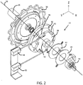
- the drive system 16 includes a plurality of drive components, including a drive motor 20, a gearbox 22, a transmission device 24 (e.g., a chain), a drive shaft 26, one or more band engagement members 28, 30 (e.g., sprockets), and an escalator step band 31.
- the escalator step band 31 includes structure (not shown) that enables a plurality of escalator steps (not shown) to be attached thereto.
- the gearbox 22 includes an input portion and an output portion.
- the input and output portions of the gearbox 22 are in geared connection with one another.
- the drive shaft 26 extends along an axial centerline 33, between a first end portion and an opposing second end portion.
- the first and second end portions of the drive shaft 26 rotate within first and second bearings (not shown), respectively.
- the first and second bearings are connected to opposing walls of the escalator housing 18 using respective first and second truss members 27, 29.
- the transmission device 24 is a chain.
- the drive motor 20 is connected to the input portion of the gearbox 22.
- the output portion of the gearbox 22 engages the transmission device 24.
- the transmission device 24 engages the first end portion of the drive shaft 26.
- a first band engagement member 28 (hereinafter the “first sprocket 28") is connected to the first end portion of the drive shaft 26.
- a second band engagement member 30 (hereinafter the “second sprocket 30”) is connected to the second end portion of the drive shaft 26.
- the first and second sprockets 28, 30 each include an annular base portion connected to the outer surface of the drive shaft 26, an annular web portion that extends radially outward from the base portion, and a plurality of teeth that extend radially outward from the web portion.
- the teeth of the first and second sprockets 28, 30 are operable to engage the escalator step band 31 to transfer rotational energy from the drive shaft 26 to the escalator step band 31.
- the brake 10 can be configured within the escalator system 12 in various different ways.
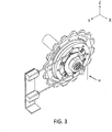
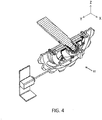
- the brake 10 is an auxiliary brake that is disposed relative to the drive shaft 26 and the second sprocket 30.
- the escalator system 12 additionally includes an operational brake 32 disposed relative to the drive motor 20 and the gearbox 22.
- the brake 10 is actuated by a reversal in direction of movement of the drive components.
- actuated and variations thereof, are not used herein to imply that a separate actuator is (or is not) provided.
- a separate actuator is not provided; the brake 10 is self-actuated by a reversal in direction of movement of the drive components, as will be described below.
- a separate actuator is provided.
- the brake 10 when the brake 10 is actuated by a reversal in direction of movement of the drive components the brake 10, as described above, the brake 10 instantaneously brakes (e.g., slows and/or stops movement of) one or more drive components of the drive system 16.
- the term "instantaneous”, and variations thereof, are used herein to describe that the braking action of the brake 10 is almost immediate; the term “instantaneous”, and variations thereof, are not used herein to describe that the braking action of the brake 10 occurs within an infinitely short time period.
- the brake 10 can be contrasted with a progressive brake, which is operable to brake drive components only after a substantially longer time period.
- the brake 10 can instantaneously brake one or more drive components of the drive system 16 at a deceleration rate that is significantly higher than a deceleration rate of a comparable progressive brake or the safety code dictated rate.
- the brake 10 can instantaneously brake one or more drive components at a deceleration rate (e.g., 2 m/s 2 , 3 m/s 2 , 4 m/s 2 , 5 m/s 2 ) that is significantly higher than 1 m/s 2 .
- the brake 10 is additionally operable to hold a position of one or more drive components of the drive system 16 (e.g., the escalator step band 31) after movement of the drive components has stopped.
- the brake 10 can be used, for example, to hold a position of an elevator car at a landing.
- the brake 10 is operable to brake one or more drive components of the drive system 16 when the drive components are moved in a desired direction (e.g., a forward direction, an upward direction, a downward direction), and the brake 10 is independently operable to brake (e.g., slow and/or stop movement of) the drive components when there is a reversal in direction of movement of the drive components.
- a desired direction e.g., a forward direction, an upward direction, a downward direction
- the brake 10 is independently operable to brake (e.g., slow and/or stop movement of) the drive components when there is a reversal in direction of movement of the drive components.
- the brake 10 can be implemented in various different ways. Referring to FIG. 2 , in the illustrated embodiment, the brake 10 includes an outer ring 36, an inner block 38, one or more rollers 40, a roller dial plate 42, a first actuator 44, one or more wedges 46, a wedge dial plate 48, and a second actuator 50.
- the outer ring 36 includes a radially inner surface, a radially outer surface, and first and second face surfaces that extend radially between the inner and outer surfaces.
- the first face surface of the outer ring 36 is connected to a face surface of the second sprocket 30 such that the outer ring 36 and the second sprocket 30 each are concentrically aligned about the centerline 33.
- the inner block 38 includes an annular base portion and an annular web portion that extends radially outward from the base portion.
- the base portion of the inner block 38 includes an aperture through which the drive shaft 26 (see FIGS. 1 and 2 ) is operable to freely rotate.
- the inner block 38 includes an annular flange 52 (see also FIG. 2 ) that extends axially from the base portion of the inner block 38.
- the annular flange 52 is positionally-fixed relative to a pedestal 54 (see FIG. 2 ).
- the pedestal 54 is positionally-fixed relative to the second truss member 29 (see FIG. 1 ).
- the inner block 38 is shaped such that it includes a plurality of peaks 56 and a plurality of recesses 58. Each of the recesses 58 is disposed circumferentially between two of the peaks 56. Each of the peaks 56 forms a portion of the radially outer surface of the inner block 38 (hereinafter a "peak portion 60 of the outer surface”). Each of the recesses 58 form a portion of the radially outer surface of the inner block 38 (hereinafter a "recess portion 62 of the outer surface”).
- Each of the peak portions 60 of the outer surface extend circumferentially about the axial centerline 61 of the inner block 38 such that the radially-extending distances between the axial centerline 61 and the peak portions 60 (hereinafter the "peak radii") are at least substantially equal across the entirety of each peak portion 60, and are at least substantially equal from one peak portion 60 to the next.
- Each of the recesses 58 extend radially into the web portion of the inner block 38 such that the radially-extending distances between the axial centerline 61 and the recess portions 62 (hereinafter the "recess radii") are less than the peak radii.
- the recesses 58 of the inner block 38 are shaped such that each of the recess portions 62 of the outer surface of the inner block 38 are defined by a plurality of recess radii.
- the recesses 58 are shaped such that each of the recess portions 62 of the outer surface extend circumferentially from a first end 64 of the recess portion 62 having a first recess radius to a second end 66 of the of the recess portion 62 having a second recess radius that is greater than the first recess radius.
- the inner block 38 is configured such that, when the inner block 38 and the outer ring 36 are axially and concentrically aligned, the inner block 38 is disposed within the cavity defined by the inner surface of the outer ring 36, and such that the peak portions 60 of the outer surface slidably engage the inner surface of the outer ring 36, and such that a radially- and circumferentially-extending channel is formed between each recess portion 62 of the outer surface of the inner block 38 and the inner surface of the outer ring 36.
- a plurality of rollers 40 and a plurality of wedges 46 are positioned within the channels in an alternating manner as shown in the drawings.
- each roller 40 includes a cylindrical roller body that extends along an axial centerline, and a cylindrical roller flange that extends from the roller body along a lengthwise-extending axis that is co-axial with the axial centerline of the roller body.
- Each roller 40 is positioned within one of the above-described channels such that the roller body contacts a recess portion 62 of the outer surface of the inner block 38.
- each roller 40 is operable to be moved between an inactive position and an active position.
- the roller 40 when a roller 40 is in the inactive position, the roller 40 is disposed proximate the first end 64 of the recess portion 62 of the outer surface of the inner block 38 (see FIG. 5 ).
- the roller 40 When a roller 40 is in the active position, the roller 40 is disposed proximate the second end 66 of the recess portion 62 of the outer surface of the inner block 38 (see FIG. 5 ).
- the roller dial plate 42 includes an annular base portion and an annular web portion that extends radially outward from the base portion.
- the base portion of the roller dial plate 42 includes an aperture through which the annular flange 52 of the inner block 38 is disposed.
- the roller dial plate 42 is disposed relative to the annular flange 52 of the inner block 38 such that the roller dial plate 42 is operable to freely rotate about the annular flange 52 when the inner block 38 and the roller dial plate 42 are concentrically aligned.
- the roller dial plate 42 includes a plurality of arms that extend radially outward from the web portion of the of the roller dial plate 42. Each of the arms includes a radially extending channel that is operable to receive the cylindrical roller flange of a roller 40.
- the wedge 46 includes a wedge body that is connected to a wedge base by a plurality of springs, and a cylindrical wedge flange that extends from the wedge body along a lengthwise-extending axis.
- each wedge 46 is positioned within one of the above-described channels such that the wedge base contacts a recess portion 62 of the outer surface of the inner block 38 (see FIG. 5 ).
- each wedge 46 is operable to be moved between an inactive position and an active position.
- the wedge 46 when the wedge 46 is in the inactive position, the wedge 46 is disposed proximate the first end 64 of the recess portion 62 of the outer surface of the inner block 38 (see FIG. 5 ).
- the wedge 46 when the wedge 46 is in the active position, the wedge 46 is disposed proximate the second end 66 of the recess portion 62 of the outer surface of the inner block 38 (see FIG. 5 ).
- the wedge dial plate 48 includes an annular base portion and an annular web portion that extends radially outward from the base portion.
- the base portion of the wedge dial plate 48 includes an aperture through which the annular flange 52 of the inner block 38 is disposed.
- the wedge dial plate 48 is disposed relative to the annular flange 52 of the inner block 38 such that the wedge dial plate 48 is operable to freely rotate about the annular flange 52 when the inner block 38 and the wedge dial plate 48 are concentrically aligned.
- the wedge dial plate 48 includes a plurality of arms that extend radially outward from the web portion of the of the wedge dial plate 48. Each of the arms includes a radially extending channel that is operable to receive the cylindrical wedge flange of a wedge 46.
- the second actuator 50 is operable to move at least one of the rollers 40 between the inactive position and the active position
- the first actuator 44 is independently operable to move at least one of the wedges 46 between the inactive position and the active position, as will be described further below.
- the roller dial plate 42 engages the cylindrical roller flanges such that movement of one of the rollers 40 from the inactive position to the active position causes movement of the other rollers 40 from the inactive position to the active position, and vice versa.
- the wedge dial plate 48 engages the cylindrical wedge flanges such that movement of one of the wedges 46 from the inactive position to the active position causes movement of the other wedges 46 from the inactive position to the active position, and vice versa.
- the escalator system 12 additionally includes a controller (not shown) that is operable to control the brake 10.
- the controller is operable to independently control the first and second actuators 44, 46 to perform the functionality described herein.
- the functionality of the controller may be implemented using hardware, software, firmware, or a combination thereof.
- the controller includes one or more programmable processors. A person having ordinary skill in the art would be able to adapt (e.g., program) the controller to perform the functionality described herein without undue experimentation.
- the drive motor 20 rotationally drives the input portion of the gearbox 22, which drives the output portion of the gearbox 22, which drives the transmission device 24, which drives the drive shaft 26, which drives the first and second sprockets 28, 30, which drive the escalator step band 31.
- movement of the first and second sprockets 28, 30 causes corresponding movement of the outer ring 36 (see FIG. 2 ) of the brake 10.
- the escalator system 12 can convey passengers from a lower level of a building to a higher level of a building (e.g., during "upward running travel"), or the escalator 12 can convey passengers from a higher level of a building to a lower level of a building (e.g., during "downward running travel”).
- FIGS. 7-8 include arrows to indicate the direction of rotation of the outer ring 36 of the brake 10, which corresponds to the direction of rotation of the escalator step band 31 (see FIG. 1 ).
- FIG. 7 illustrates clockwise rotation of the outer ring 36, which corresponds to movement of the escalator step band 31 in a desired direction during upward running travel.
- FIG. 8 illustrates counterclockwise rotation of the outer ring 36, which corresponds to movement of the escalator step band 31 in a desired direction during downward running travel.
- FIG. 7 illustrates the rollers 40 in the active position, and the wedges 46 in the inactive position.
- FIG. 8 illustrates the rollers in the inactive position, and the wedges 46 in the active position.
- the brake 10 can be configured as shown in FIG. 7 .
- the rollers 40 interact with the inner block 38 and the outer ring 36 without braking or holding the second sprocket 30.
- the brake 10 When the direction of rotation of the outer ring 36 is reversed (e.g., during a malfunction condition of the escalator system 12), the brake 10 is self-actuated, and the rollers 40 interact with the inner block and the outer ring 36 to instantaneously brake and hold the outer ring 36, which in turn instantaneously brakes and holds the second sprocket 30 and the escalator step band 31 (see FIG. 1 ).
- the brake 10 is thus operable to instantaneously prevent a reversal in the direction of rotation of the escalator step band 31, and thus can be described as providing instantaneous reversal protection. This feature of the brake 10 provides significant advantages over other brakes that can provide only progressive reversal protection.
- the brake 10 can provide instantaneous reversal protection, the brake 10 can prevent situations in which passengers are at a risk of falling while movement of the escalator step band 31 in the reverse direction is progressively slowed and stopped.
- the brake 10 can be used as a safety mechanism to prevent reversal in the movement direction of an elevator car in the event of a system failure.
- the brake 10 is operable to provide instantaneous reversal protection by mechanical means, and thus provides significant advantages over other brakes that provide reversal protection only in response to an electrical control signal.
- the brake 10 can be configured as shown in FIG. 8 .
- the wedges 46 can be moved from the inactive position to the active position, as shown in FIG. 8 .
- the first actuator 44 can move the wedges 46 to the active position in response to a signal from the controller (not shown) that indicates the overspeed condition of the escalator system 12.
- the wedges 46 can interact with the inner block and the outer ring 36 to progressively brake the outer ring 36, which in turn progressively brakes the second sprocket 30 and the escalator step band 31 (see FIG. 1 ).
- the brake 10 is thus operable to decrease the speed of the escalator step band 31 to return the escalator system to a normal operation condition, and can therefore be described as providing overspeed protection.
- the interaction with the inner block and the outer ring 36 can, by itself, move the wedges 46 further toward the respective second ends 66 of the of the recess portions 62 of the inner block 38, until the wedges 46 interact with the inner block and the outer ring 36 to hold the outer ring 36.
Landscapes
- Escalators And Moving Walkways (AREA)
Claims (12)
- Bremse (10) zur Verwendung in einem Personenbeförderungssystem (12), wobei das Personenbeförderungssystem ein Antriebssystem (16) beinhaltet, das dazu betrieben werden kann, eine Antriebskomponente (30) in eine gewünschte Richtung anzutreiben, wobei die Bremse durch eine Umkehr in der Bewegungsrichtung der Antriebskomponente betätigt wird;
wobei das Antriebssystem dazu betrieben werden kann, die Antriebskomponente in die gewünschte Richtung drehend anzutreiben; und
wobei die Bremse Folgendes umfasst:einen äußeren Ring (36), der mit der Antriebskomponente derart verbunden ist, dass der äußere Ring und die Antriebskomponente konzentrisch um eine Drehachse (33) ausgerichtet sind; undeinen inneren Block (38), der derart innerhalb eines Hohlraums angeordnet ist, der durch den äußeren Ring definiert ist, dass der innere Block und der äußere Ring axial und konzentrisch ausgerichtet sind, wobei der innere Block derart konfiguriert ist, dass ein erster Kanal (58)zwischen dem inneren Block und dem äußeren Ring gebildet ist;wobei die Bremse (10) ferner dadurch gekennzeichnet ist, dass sie Folgendes umfasst:- eine erste Laufrolle (40), die innerhalb des ersten Kanals (58) positioniert ist, wobei die erste Laufrolle innerhalb des ersten Kanals zwischen einer aktiven Position und einer inaktiven Position beweglich ist, und vorzugsweise einen Aktor (50) beinhaltet, der dazu betrieben werden kann, die erste Laufrolle zwischen der aktiven Position und der inaktiven Position zu bewegen; oder- einen ersten Keil (46), der innerhalb des ersten Kanals (58) positioniert ist, wobei der erste Keil innerhalb des ersten Kanals zwischen einer aktiven Position und einer inaktiven Position beweglich ist. - Bremse (10) nach Anspruch 1, wobei das Personenbeförderungssystem (12) ein Fahrstuhlsystem oder ein Rolltreppensystem ist.
- Bremse (10) nach Anspruch 1 oder 2, wobei die Bremse die Antriebskomponente (30) unmittelbar bremst, wenn sie durch die Umkehr der Bewegungsrichtung der Antriebskomponente betätigt wird, und wobei die Bremse vorzugsweise die Bewegung der Antriebskomponente mit einer Abbremsrate größer als 1 Meter/Sekunde2 verlangsamt.
- Bremse (10) nach Anspruch 1 oder 2, wobei die Bremse die Antriebskomponente (30) schrittweise bremst, wenn sie durch die Umkehr der Bewegungsrichtung der Antriebskomponente betätigt wird.
- Bremse (10) nach einem der vorstehenden Ansprüche, wobei die Bremse dazu betrieben werden kann, die Antriebskomponente (30) zu bremsen, um einen Zustand überhöhter Geschwindigkeit zu verhindern, bei dem sich die Antriebskomponente in die gewünschte Richtung mit einer Geschwindigkeit bewegt, die über einem vorbestimmten Schwellenwert liegt.
- Bremse (10) nach Anspruch 1, wobei, wenn sich die erste Laufrolle (40) in der aktiven Position befindet, die erste Laufrolle dazu betrieben werden kann, mit dem inneren Block (38) und dem äußeren Ring (36) zu interagieren, um den äußeren Ring unmittelbar zu bremsen, was wiederum unmittelbar die Antriebskomponente (30) des Antriebssystems (16) bremst; und
wobei, wenn sich die erste Laufrolle in der inaktiven Position befindet, die erste Laufrolle nicht dazu betrieben werden kann, mit dem inneren Block und dem äußeren Ring zu interagieren, um den äußeren Ring unmittelbar zu bremsen. - Bremse nach Anspruch 1, wobei, wenn sich der erste Keil (46) in der aktiven Position befindet, der erste Keil dazu betrieben werden kann, mit dem inneren Block (38) und dem äußeren Ring (36) zu interagieren, um den äußeren Ring zu bremsen, was wiederum die Antriebskomponente (30) des Antriebssystems (16) bremst; und
wobei, wenn sich der erste Keil in der inaktiven Position befindet, der erste Keil nicht dazu betrieben werden kann, mit dem inneren Block und dem äußeren Ring zu interagieren, um den äußeren Ring zu bremsen. - Bremse (10) nach Anspruch 7, wobei Interaktion zwischen dem ersten Keil (46), dem inneren Block (38) und dem äußeren Ring (36) selbst dazu betrieben werden kann, den ersten Keil innerhalb des ersten Kanals (58) zu bewegen bis der erste Keil, der innere Block und der äußere Ring interagieren, um den äußeren Ring zu halten.
- Bremse (10) nach Anspruch 1, 7 oder 8, ferner einen Aktor (44) beinhaltend, der dazu betrieben werden kann, den ersten Keil (46) zwischen der aktiven Position und der inaktiven Position zu bewegen.
- Bremse (10) nach einem der vorstehenden Ansprüche, wobei die Bremse durch die Umkehr in der Bewegungsrichtung der Antriebskomponente selbstbetätigt wird.
- Personenbeförderungssystem (12), Folgendes umfassend:ein Antriebssystem (16), das dazu betrieben werden kann, eine Antriebskomponente (30) in eine erste Richtung zu bewegen;eine Bremse (10) nach einem der vorstehenden Ansprüche;wobei die Bremse dazu betrieben werden kann, die Antriebskomponente zu bremsen, um einen Zustand überhöhter Geschwindigkeit zu verhindern, bei dem sich die Antriebskomponente in die erste Richtung mit einer Geschwindigkeit bewegt, die größer als ein vorbestimmter Schwellenwert ist, und dazu betrieben werden kann, die Antriebskomponente zu bremsen, um Bewegung der Antriebskomponente in eine zweite Richtung zu verhindern, die der ersten Richtung entgegengesetzt ist, wobei die Bremse durch eine Änderung der Bewegungsrichtung der Antriebskomponente von der ersten Richtung zu der zweiten Richtung betätigt wird.
- Verfahren zum Betreiben eines Personenbeförderungssystems (12), Folgendes umfassend:Betreiben eines Antriebssystems (16) des Personenbeförderungssystems derart, dass eine Antriebskomponente (30) des Antriebssystems in eine gewünschte Richtung angetrieben wird; undBetätigen einer Bremse (10), wobei die Bremse durch eine Änderung der Bewegungsrichtung der Antriebskomponente von der gewünschten Richtung zu einer umgekehrten Richtung betätigt wird;wobei das Antriebssystem betrieben wird, um die Antriebskomponente in die gewünschte Richtung anzutreiben; undwobei die Bremse Folgendes umfasst:einen äußeren Ring (36), der mit der Antriebskomponente derart verbunden ist, dass der äußere Ring und die Antriebskomponente konzentrisch um eine Drehachse (33) ausgerichtet sind; undeinen inneren Block (38), der derart innerhalb eines Hohlraums angeordnet ist, der durch den äußeren Ring definiert ist, dass der innere Block und der äußere Ring axial und konzentrisch ausgerichtet sind, wobei der innere Block derart konfiguriert ist, dass ein erster Kanal (58)zwischen dem inneren Block und dem äußeren Ring gebildet ist;wobei die Bremse (10) ferner dadurch gekennzeichnet ist, dass sie Folgendes umfasst:- eine erste Laufrolle (40), die innerhalb des ersten Kanals (58) positioniert ist, wobei die erste Laufrolle innerhalb des ersten Kanals zwischen einer aktiven Position und einer inaktiven Position beweglich ist, und vorzugsweise einen Aktor (50) beinhaltet, der dazu betrieben werden kann, die erste Laufrolle zwischen der aktiven Position und der inaktiven Position zu bewegen; oder- einen ersten Keil (46), der innerhalb des ersten Kanals (58) positioniert ist, wobei der erste Keil innerhalb des ersten Kanals zwischen einer aktiven Position und einer inaktiven Position beweglich ist.
Applications Claiming Priority (1)
| Application Number | Priority Date | Filing Date | Title |
|---|---|---|---|
| PCT/CN2013/087356 WO2015070462A1 (en) | 2013-11-18 | 2013-11-18 | Brake for use in passenger conveyor system |
Publications (3)
| Publication Number | Publication Date |
|---|---|
| EP3071502A1 EP3071502A1 (de) | 2016-09-28 |
| EP3071502A4 EP3071502A4 (de) | 2017-07-26 |
| EP3071502B1 true EP3071502B1 (de) | 2019-07-03 |
Family
ID=53056670
Family Applications (1)
| Application Number | Title | Priority Date | Filing Date |
|---|---|---|---|
| EP13897548.7A Not-in-force EP3071502B1 (de) | 2013-11-18 | 2013-11-18 | Bremse zur verwendung in einem personenbeförderungssystem |
Country Status (4)
| Country | Link |
|---|---|
| US (1) | US9994428B2 (de) |
| EP (1) | EP3071502B1 (de) |
| CN (1) | CN105745170B (de) |
| WO (1) | WO2015070462A1 (de) |
Cited By (1)
| Publication number | Priority date | Publication date | Assignee | Title |
|---|---|---|---|---|
| EP4238921B1 (de) * | 2022-03-03 | 2024-02-28 | TK Escalator Norte, S.A. | Bremsvorrichtung für ein aufzugs- oder fahrtreppensystem |
Families Citing this family (5)
| Publication number | Priority date | Publication date | Assignee | Title |
|---|---|---|---|---|
| CN105936454B (zh) * | 2016-06-08 | 2017-12-15 | 石家庄君安消防设备科技有限公司 | 恒速控制装置 |
| EP3339236B1 (de) * | 2016-12-21 | 2020-06-17 | Otis Elevator Company | Selbstbremsendes getriebe und personenförderer mit einem selbstbremsenden getriebe |
| EP3676209A4 (de) * | 2017-08-30 | 2020-08-19 | KONE Corporation | Personenförderer |
| CN108217413A (zh) * | 2017-12-28 | 2018-06-29 | 上海市特种设备监督检验技术研究院 | 一种自动扶梯附加制动器检验方法 |
| CN111661751B (zh) * | 2020-06-15 | 2022-02-01 | 东营胜华科贸有限公司 | 一种利用离心力原理的吊船吊索失速自锁保险结构 |
Family Cites Families (35)
| Publication number | Priority date | Publication date | Assignee | Title |
|---|---|---|---|---|
| US2408203A (en) | 1942-12-30 | 1946-09-24 | Westinghouse Electric Corp | Moving stairway |
| US2460017A (en) | 1946-06-06 | 1949-01-25 | Otis Elevator Co | Moving stairway brake |
| US3830344A (en) * | 1973-02-15 | 1974-08-20 | Reliance Electric Co | Brake and control therefor |
| US4231452A (en) | 1978-12-28 | 1980-11-04 | Westinghouse Electric Corp. | Spring applied, electric released drum brake |
| US4664247A (en) * | 1984-04-30 | 1987-05-12 | Westinghouse Electric Corp. | Conveyor brake control |
| US4600865A (en) | 1984-10-29 | 1986-07-15 | Westinghouse Electric Corp. | Transportation apparatus |
| JPH04145919A (ja) * | 1990-10-04 | 1992-05-19 | Kotaro Matsui | 巻線多重回転機 |
| RU2044683C1 (ru) * | 1992-12-31 | 1995-09-27 | Научно-производственная фирма "Ньютон" | Вертикальный ковшовый элеватор |
| US5337878A (en) * | 1993-12-28 | 1994-08-16 | Otis Elevator Company | Assembly and method for adjusting brake force for passenger conveyor emergency brake |
| JPH1095586A (ja) * | 1996-09-24 | 1998-04-14 | Hitachi Ltd | 乗客コンベアの運転方法 |
| DE19723897A1 (de) | 1997-06-05 | 1998-12-10 | O & K Rolltreppen Gmbh | Sicherheitseinrichtung für Personenförderanlagen |
| DE19803899C2 (de) | 1998-02-02 | 2000-04-13 | O & K Rolltreppen Gmbh | Verfahren zum Abbremsen von Rolltreppen bzw. Rollsteigen sowie Bremseinrichtung für Rolltreppen bzw. Rollsteige |
| US6155401A (en) * | 1998-02-13 | 2000-12-05 | Inventio Ag | Drive for an escalator |
| DE19935521C2 (de) | 1999-07-28 | 2001-07-19 | Kone Corp | Verfahren zur Regelung der Bremse(n) einer Rolltreppe oder eines Rollsteiges |
| DE10027490C2 (de) | 2000-06-02 | 2003-12-04 | Kone Corp | Sicherheitseinrichtung für Rolltreppen und Rollsteige |
| US6966420B2 (en) * | 2000-06-19 | 2005-11-22 | Otis Elevator Company | Drive unit for escalators or moving sidewalks |
| KR100388156B1 (ko) * | 2000-10-21 | 2003-06-25 | 편준기 | 엘리베이터용 로프 제동장치 |
| US20030000798A1 (en) | 2001-05-31 | 2003-01-02 | Williams Todd Y. | Universal escalator control system |
| CN1239378C (zh) | 2001-12-24 | 2006-02-01 | 因温特奥股份公司 | 停止人员输送设备运行的方法及监控制动装置的安全电路 |
| AU2003210227A1 (en) * | 2003-02-07 | 2004-08-30 | Otis Elevator Company | Passenger conveyor drive machine |
| ZA200405180B (en) | 2003-07-31 | 2005-03-11 | Inventio Ag | Drive equipment for escalator step or moving walkway plate. |
| US6971496B1 (en) | 2004-07-09 | 2005-12-06 | Kone Corporation | Escalator braking with multiple deceleration rates |
| DE102004038022A1 (de) | 2004-08-04 | 2006-03-16 | Ortlinghaus-Werke Gmbh | Sicherheitsbremse |
| JP2006143424A (ja) * | 2004-11-22 | 2006-06-08 | Mitsubishi Electric Corp | 乗客コンベアの非常制動装置 |
| GB2410484B (en) * | 2005-03-29 | 2006-05-31 | Comeup Ind Inc | Brake apparatus for winch |
| FR2885895B3 (fr) * | 2005-05-21 | 2007-05-11 | Comeup Ind Inc | Appareil de freinage pour treuil |
| NZ575464A (en) | 2009-03-10 | 2010-07-30 | Holmes Solutions Ltd | Improvements in and relating to braking mechanisms |
| CN102459056B (zh) * | 2009-06-16 | 2014-03-12 | 奥的斯电梯公司 | 乘客输送机及其主驱动轴制动器以及控制该制动器的方法 |
| JP2011046483A (ja) * | 2009-08-27 | 2011-03-10 | Mitsubishi Electric Corp | 乗客コンベアの主軸ブレーキ |
| US7950514B1 (en) | 2009-11-06 | 2011-05-31 | Kone Corporation | Apparatus and method for variable torque braking of escalators and moving walkways |
| KR200466157Y1 (ko) * | 2011-07-01 | 2013-04-03 | 주식회사 송산특수엘리베이터 | 고하중용 에스컬레이터의 디스크 유압캘리퍼식 비상정지 안전 브레이크 제어장치 |
| CN102398845B (zh) * | 2011-11-28 | 2013-09-04 | 江南嘉捷电梯股份有限公司 | 自动扶梯或自动人行道的防逆转装置 |
| ES2378627B1 (es) | 2011-12-14 | 2013-01-23 | Thyssenkrupp Elevator Innovation Center, S.A. | Sistema de frenado para escaleras mecánicas y pasillos móviles. |
| DE102012003178B4 (de) * | 2012-02-17 | 2018-03-22 | Kone Corp. | Einrichtung zur Überwachung der Funktion einer Rolltreppe oder eines Rollsteiges |
| CN202848837U (zh) * | 2012-11-06 | 2013-04-03 | 嵊州市特种链轮有限公司 | 一种新型自动扶梯驱动机构 |
-
2013
- 2013-11-18 EP EP13897548.7A patent/EP3071502B1/de not_active Not-in-force
- 2013-11-18 WO PCT/CN2013/087356 patent/WO2015070462A1/en not_active Ceased
- 2013-11-18 CN CN201380081016.3A patent/CN105745170B/zh not_active Expired - Fee Related
- 2013-11-18 US US15/033,843 patent/US9994428B2/en active Active
Non-Patent Citations (1)
| Title |
|---|
| None * |
Cited By (1)
| Publication number | Priority date | Publication date | Assignee | Title |
|---|---|---|---|---|
| EP4238921B1 (de) * | 2022-03-03 | 2024-02-28 | TK Escalator Norte, S.A. | Bremsvorrichtung für ein aufzugs- oder fahrtreppensystem |
Also Published As
| Publication number | Publication date |
|---|---|
| EP3071502A1 (de) | 2016-09-28 |
| US20160251204A1 (en) | 2016-09-01 |
| CN105745170A (zh) | 2016-07-06 |
| CN105745170B (zh) | 2018-07-03 |
| WO2015070462A1 (en) | 2015-05-21 |
| EP3071502A4 (de) | 2017-07-26 |
| US9994428B2 (en) | 2018-06-12 |
Similar Documents
| Publication | Publication Date | Title |
|---|---|---|
| EP3071502B1 (de) | Bremse zur verwendung in einem personenbeförderungssystem | |
| CN103241636B (zh) | 乘客输送机 | |
| EP2447201A1 (de) | Aufzugsvorrichtung | |
| JP2010208825A (ja) | 乗客コンベアの補助ブレーキ装置 | |
| EP2540653B1 (de) | Bremsvorrichtung für einen Passagierförderer | |
| EP2787240B1 (de) | Bremse und Aufzug | |
| KR100995059B1 (ko) | 에스컬레이터의 비상정지 안전 브레이크 제어장치 | |
| US5201821A (en) | Disc brake elevator drive sheave | |
| CN102101619A (zh) | 电梯的制动装置 | |
| JP6834022B2 (ja) | 安全装置、および、それを備えたエレベーター | |
| EP2001783B1 (de) | Anordnung zum anhalten einer aufzugskabine in einer notbremssituation und aufzug | |
| JP5845317B2 (ja) | エレベータの調速機 | |
| JP6289259B2 (ja) | エスカレータの非常制動装置およびエスカレータ | |
| EP3147253B1 (de) | Elevator brakeaufzugsbremsenanordnung | |
| CN111032560B (zh) | 乘客输送机 | |
| CN104066671B (zh) | 用于乘客传送器的辅助制动器 | |
| JP6253777B2 (ja) | 乗客コンベヤの安全装置 | |
| WO2003089354A1 (fr) | Systeme de freinage d'urgence destine a un ascenseur | |
| JP2019059557A (ja) | 乗客コンベア装置 | |
| US20180251336A1 (en) | Elevator brake | |
| US20100018810A1 (en) | Elevator apparatus | |
| IT202100003905A1 (it) | Freno di emergenza | |
| US12291429B2 (en) | Auxiliary brake for passenger conveyors | |
| JP6303848B2 (ja) | 乗客コンベアの緩停止装置 | |
| KR20190018981A (ko) | 에스컬레이터 보조브레이크 시스템 |
Legal Events
| Date | Code | Title | Description |
|---|---|---|---|
| PUAI | Public reference made under article 153(3) epc to a published international application that has entered the european phase |
Free format text: ORIGINAL CODE: 0009012 |
|
| 17P | Request for examination filed |
Effective date: 20160617 |
|
| AK | Designated contracting states |
Kind code of ref document: A1 Designated state(s): AL AT BE BG CH CY CZ DE DK EE ES FI FR GB GR HR HU IE IS IT LI LT LU LV MC MK MT NL NO PL PT RO RS SE SI SK SM TR |
|
| AX | Request for extension of the european patent |
Extension state: BA ME |
|
| DAX | Request for extension of the european patent (deleted) | ||
| REG | Reference to a national code |
Ref country code: DE Ref legal event code: R079 Ref document number: 602013057539 Country of ref document: DE Free format text: PREVIOUS MAIN CLASS: B66B0005040000 Ipc: B66B0023020000 |
|
| A4 | Supplementary search report drawn up and despatched |
Effective date: 20170627 |
|
| RIC1 | Information provided on ipc code assigned before grant |
Ipc: B66B 29/00 20060101ALI20170621BHEP Ipc: B66B 23/02 20060101AFI20170621BHEP |
|
| RAP1 | Party data changed (applicant data changed or rights of an application transferred) |
Owner name: OTIS ELEVATOR COMPANY |
|
| GRAP | Despatch of communication of intention to grant a patent |
Free format text: ORIGINAL CODE: EPIDOSNIGR1 |
|
| STAA | Information on the status of an ep patent application or granted ep patent |
Free format text: STATUS: GRANT OF PATENT IS INTENDED |
|
| INTG | Intention to grant announced |
Effective date: 20190114 |
|
| GRAS | Grant fee paid |
Free format text: ORIGINAL CODE: EPIDOSNIGR3 |
|
| GRAA | (expected) grant |
Free format text: ORIGINAL CODE: 0009210 |
|
| STAA | Information on the status of an ep patent application or granted ep patent |
Free format text: STATUS: THE PATENT HAS BEEN GRANTED |
|
| AK | Designated contracting states |
Kind code of ref document: B1 Designated state(s): AL AT BE BG CH CY CZ DE DK EE ES FI FR GB GR HR HU IE IS IT LI LT LU LV MC MK MT NL NO PL PT RO RS SE SI SK SM TR |
|
| REG | Reference to a national code |
Ref country code: GB Ref legal event code: FG4D |
|
| REG | Reference to a national code |
Ref country code: CH Ref legal event code: EP Ref country code: AT Ref legal event code: REF Ref document number: 1150759 Country of ref document: AT Kind code of ref document: T Effective date: 20190715 |
|
| REG | Reference to a national code |
Ref country code: IE Ref legal event code: FG4D |
|
| REG | Reference to a national code |
Ref country code: DE Ref legal event code: R096 Ref document number: 602013057539 Country of ref document: DE |
|
| REG | Reference to a national code |
Ref country code: NL Ref legal event code: MP Effective date: 20190703 |
|
| REG | Reference to a national code |
Ref country code: LT Ref legal event code: MG4D |
|
| REG | Reference to a national code |
Ref country code: AT Ref legal event code: MK05 Ref document number: 1150759 Country of ref document: AT Kind code of ref document: T Effective date: 20190703 |
|
| PG25 | Lapsed in a contracting state [announced via postgrant information from national office to epo] |
Ref country code: NL Free format text: LAPSE BECAUSE OF FAILURE TO SUBMIT A TRANSLATION OF THE DESCRIPTION OR TO PAY THE FEE WITHIN THE PRESCRIBED TIME-LIMIT Effective date: 20190703 Ref country code: AT Free format text: LAPSE BECAUSE OF FAILURE TO SUBMIT A TRANSLATION OF THE DESCRIPTION OR TO PAY THE FEE WITHIN THE PRESCRIBED TIME-LIMIT Effective date: 20190703 Ref country code: SE Free format text: LAPSE BECAUSE OF FAILURE TO SUBMIT A TRANSLATION OF THE DESCRIPTION OR TO PAY THE FEE WITHIN THE PRESCRIBED TIME-LIMIT Effective date: 20190703 Ref country code: LT Free format text: LAPSE BECAUSE OF FAILURE TO SUBMIT A TRANSLATION OF THE DESCRIPTION OR TO PAY THE FEE WITHIN THE PRESCRIBED TIME-LIMIT Effective date: 20190703 Ref country code: PT Free format text: LAPSE BECAUSE OF FAILURE TO SUBMIT A TRANSLATION OF THE DESCRIPTION OR TO PAY THE FEE WITHIN THE PRESCRIBED TIME-LIMIT Effective date: 20191104 Ref country code: BG Free format text: LAPSE BECAUSE OF FAILURE TO SUBMIT A TRANSLATION OF THE DESCRIPTION OR TO PAY THE FEE WITHIN THE PRESCRIBED TIME-LIMIT Effective date: 20191003 Ref country code: HR Free format text: LAPSE BECAUSE OF FAILURE TO SUBMIT A TRANSLATION OF THE DESCRIPTION OR TO PAY THE FEE WITHIN THE PRESCRIBED TIME-LIMIT Effective date: 20190703 Ref country code: FI Free format text: LAPSE BECAUSE OF FAILURE TO SUBMIT A TRANSLATION OF THE DESCRIPTION OR TO PAY THE FEE WITHIN THE PRESCRIBED TIME-LIMIT Effective date: 20190703 Ref country code: CZ Free format text: LAPSE BECAUSE OF FAILURE TO SUBMIT A TRANSLATION OF THE DESCRIPTION OR TO PAY THE FEE WITHIN THE PRESCRIBED TIME-LIMIT Effective date: 20190703 Ref country code: NO Free format text: LAPSE BECAUSE OF FAILURE TO SUBMIT A TRANSLATION OF THE DESCRIPTION OR TO PAY THE FEE WITHIN THE PRESCRIBED TIME-LIMIT Effective date: 20191003 |
|
| PG25 | Lapsed in a contracting state [announced via postgrant information from national office to epo] |
Ref country code: LV Free format text: LAPSE BECAUSE OF FAILURE TO SUBMIT A TRANSLATION OF THE DESCRIPTION OR TO PAY THE FEE WITHIN THE PRESCRIBED TIME-LIMIT Effective date: 20190703 Ref country code: IS Free format text: LAPSE BECAUSE OF FAILURE TO SUBMIT A TRANSLATION OF THE DESCRIPTION OR TO PAY THE FEE WITHIN THE PRESCRIBED TIME-LIMIT Effective date: 20191103 Ref country code: ES Free format text: LAPSE BECAUSE OF FAILURE TO SUBMIT A TRANSLATION OF THE DESCRIPTION OR TO PAY THE FEE WITHIN THE PRESCRIBED TIME-LIMIT Effective date: 20190703 Ref country code: AL Free format text: LAPSE BECAUSE OF FAILURE TO SUBMIT A TRANSLATION OF THE DESCRIPTION OR TO PAY THE FEE WITHIN THE PRESCRIBED TIME-LIMIT Effective date: 20190703 Ref country code: GR Free format text: LAPSE BECAUSE OF FAILURE TO SUBMIT A TRANSLATION OF THE DESCRIPTION OR TO PAY THE FEE WITHIN THE PRESCRIBED TIME-LIMIT Effective date: 20191004 Ref country code: RS Free format text: LAPSE BECAUSE OF FAILURE TO SUBMIT A TRANSLATION OF THE DESCRIPTION OR TO PAY THE FEE WITHIN THE PRESCRIBED TIME-LIMIT Effective date: 20190703 |
|
| PG25 | Lapsed in a contracting state [announced via postgrant information from national office to epo] |
Ref country code: TR Free format text: LAPSE BECAUSE OF FAILURE TO SUBMIT A TRANSLATION OF THE DESCRIPTION OR TO PAY THE FEE WITHIN THE PRESCRIBED TIME-LIMIT Effective date: 20190703 |
|
| PG25 | Lapsed in a contracting state [announced via postgrant information from national office to epo] |
Ref country code: DK Free format text: LAPSE BECAUSE OF FAILURE TO SUBMIT A TRANSLATION OF THE DESCRIPTION OR TO PAY THE FEE WITHIN THE PRESCRIBED TIME-LIMIT Effective date: 20190703 Ref country code: EE Free format text: LAPSE BECAUSE OF FAILURE TO SUBMIT A TRANSLATION OF THE DESCRIPTION OR TO PAY THE FEE WITHIN THE PRESCRIBED TIME-LIMIT Effective date: 20190703 Ref country code: RO Free format text: LAPSE BECAUSE OF FAILURE TO SUBMIT A TRANSLATION OF THE DESCRIPTION OR TO PAY THE FEE WITHIN THE PRESCRIBED TIME-LIMIT Effective date: 20190703 Ref country code: IT Free format text: LAPSE BECAUSE OF FAILURE TO SUBMIT A TRANSLATION OF THE DESCRIPTION OR TO PAY THE FEE WITHIN THE PRESCRIBED TIME-LIMIT Effective date: 20190703 Ref country code: PL Free format text: LAPSE BECAUSE OF FAILURE TO SUBMIT A TRANSLATION OF THE DESCRIPTION OR TO PAY THE FEE WITHIN THE PRESCRIBED TIME-LIMIT Effective date: 20190703 |
|
| PG25 | Lapsed in a contracting state [announced via postgrant information from national office to epo] |
Ref country code: SM Free format text: LAPSE BECAUSE OF FAILURE TO SUBMIT A TRANSLATION OF THE DESCRIPTION OR TO PAY THE FEE WITHIN THE PRESCRIBED TIME-LIMIT Effective date: 20190703 Ref country code: SK Free format text: LAPSE BECAUSE OF FAILURE TO SUBMIT A TRANSLATION OF THE DESCRIPTION OR TO PAY THE FEE WITHIN THE PRESCRIBED TIME-LIMIT Effective date: 20190703 Ref country code: IS Free format text: LAPSE BECAUSE OF FAILURE TO SUBMIT A TRANSLATION OF THE DESCRIPTION OR TO PAY THE FEE WITHIN THE PRESCRIBED TIME-LIMIT Effective date: 20200224 |
|
| REG | Reference to a national code |
Ref country code: DE Ref legal event code: R119 Ref document number: 602013057539 Country of ref document: DE |
|
| REG | Reference to a national code |
Ref country code: CH Ref legal event code: PL |
|
| PLBE | No opposition filed within time limit |
Free format text: ORIGINAL CODE: 0009261 |
|
| STAA | Information on the status of an ep patent application or granted ep patent |
Free format text: STATUS: NO OPPOSITION FILED WITHIN TIME LIMIT |
|
| PG2D | Information on lapse in contracting state deleted |
Ref country code: IS |
|
| PG25 | Lapsed in a contracting state [announced via postgrant information from national office to epo] |
Ref country code: MC Free format text: LAPSE BECAUSE OF FAILURE TO SUBMIT A TRANSLATION OF THE DESCRIPTION OR TO PAY THE FEE WITHIN THE PRESCRIBED TIME-LIMIT Effective date: 20190703 Ref country code: LI Free format text: LAPSE BECAUSE OF NON-PAYMENT OF DUE FEES Effective date: 20191130 Ref country code: CH Free format text: LAPSE BECAUSE OF NON-PAYMENT OF DUE FEES Effective date: 20191130 Ref country code: LU Free format text: LAPSE BECAUSE OF NON-PAYMENT OF DUE FEES Effective date: 20191118 |
|
| 26N | No opposition filed |
Effective date: 20200603 |
|
| REG | Reference to a national code |
Ref country code: BE Ref legal event code: MM Effective date: 20191130 |
|
| PG25 | Lapsed in a contracting state [announced via postgrant information from national office to epo] |
Ref country code: SI Free format text: LAPSE BECAUSE OF FAILURE TO SUBMIT A TRANSLATION OF THE DESCRIPTION OR TO PAY THE FEE WITHIN THE PRESCRIBED TIME-LIMIT Effective date: 20190703 |
|
| GBPC | Gb: european patent ceased through non-payment of renewal fee |
Effective date: 20191118 |
|
| PG25 | Lapsed in a contracting state [announced via postgrant information from national office to epo] |
Ref country code: DE Free format text: LAPSE BECAUSE OF NON-PAYMENT OF DUE FEES Effective date: 20200603 Ref country code: FR Free format text: LAPSE BECAUSE OF NON-PAYMENT OF DUE FEES Effective date: 20191130 Ref country code: GB Free format text: LAPSE BECAUSE OF NON-PAYMENT OF DUE FEES Effective date: 20191118 Ref country code: IE Free format text: LAPSE BECAUSE OF NON-PAYMENT OF DUE FEES Effective date: 20191118 |
|
| PG25 | Lapsed in a contracting state [announced via postgrant information from national office to epo] |
Ref country code: BE Free format text: LAPSE BECAUSE OF NON-PAYMENT OF DUE FEES Effective date: 20191130 |
|
| PG25 | Lapsed in a contracting state [announced via postgrant information from national office to epo] |
Ref country code: CY Free format text: LAPSE BECAUSE OF FAILURE TO SUBMIT A TRANSLATION OF THE DESCRIPTION OR TO PAY THE FEE WITHIN THE PRESCRIBED TIME-LIMIT Effective date: 20190703 |
|
| PG25 | Lapsed in a contracting state [announced via postgrant information from national office to epo] |
Ref country code: MT Free format text: LAPSE BECAUSE OF FAILURE TO SUBMIT A TRANSLATION OF THE DESCRIPTION OR TO PAY THE FEE WITHIN THE PRESCRIBED TIME-LIMIT Effective date: 20190703 Ref country code: HU Free format text: LAPSE BECAUSE OF FAILURE TO SUBMIT A TRANSLATION OF THE DESCRIPTION OR TO PAY THE FEE WITHIN THE PRESCRIBED TIME-LIMIT; INVALID AB INITIO Effective date: 20131118 |
|
| PG25 | Lapsed in a contracting state [announced via postgrant information from national office to epo] |
Ref country code: MK Free format text: LAPSE BECAUSE OF FAILURE TO SUBMIT A TRANSLATION OF THE DESCRIPTION OR TO PAY THE FEE WITHIN THE PRESCRIBED TIME-LIMIT Effective date: 20190703 |