EP3070817B1 - Stator und elektrische drehmaschine damit - Google Patents
Stator und elektrische drehmaschine damit Download PDFInfo
- Publication number
- EP3070817B1 EP3070817B1 EP14861800.2A EP14861800A EP3070817B1 EP 3070817 B1 EP3070817 B1 EP 3070817B1 EP 14861800 A EP14861800 A EP 14861800A EP 3070817 B1 EP3070817 B1 EP 3070817B1
- Authority
- EP
- European Patent Office
- Prior art keywords
- stator
- rotating machine
- electric rotating
- neutral line
- slot
- Prior art date
- Legal status (The legal status is an assumption and is not a legal conclusion. Google has not performed a legal analysis and makes no representation as to the accuracy of the status listed.)
- Active
Links
- 230000007935 neutral effect Effects 0.000 claims description 64
- 238000004804 winding Methods 0.000 claims description 34
- 239000011295 pitch Substances 0.000 claims description 16
- 230000009193 crawling Effects 0.000 claims description 8
- 239000011248 coating agent Substances 0.000 claims description 7
- 238000000576 coating method Methods 0.000 claims description 7
- XEEYBQQBJWHFJM-UHFFFAOYSA-N Iron Chemical group [Fe] XEEYBQQBJWHFJM-UHFFFAOYSA-N 0.000 claims description 3
- 239000011810 insulating material Substances 0.000 claims 1
- 239000004020 conductor Substances 0.000 description 36
- 230000005540 biological transmission Effects 0.000 description 10
- 238000003466 welding Methods 0.000 description 6
- 230000000149 penetrating effect Effects 0.000 description 3
- 238000010586 diagram Methods 0.000 description 2
- 230000000694 effects Effects 0.000 description 2
- RYGMFSIKBFXOCR-UHFFFAOYSA-N Copper Chemical compound [Cu] RYGMFSIKBFXOCR-UHFFFAOYSA-N 0.000 description 1
- 239000004593 Epoxy Substances 0.000 description 1
- 230000001154 acute effect Effects 0.000 description 1
- 238000005219 brazing Methods 0.000 description 1
- 238000001816 cooling Methods 0.000 description 1
- 230000003247 decreasing effect Effects 0.000 description 1
- 239000003822 epoxy resin Substances 0.000 description 1
- 238000003780 insertion Methods 0.000 description 1
- 230000037431 insertion Effects 0.000 description 1
- 229910052742 iron Inorganic materials 0.000 description 1
- 238000000034 method Methods 0.000 description 1
- 238000012986 modification Methods 0.000 description 1
- 230000004048 modification Effects 0.000 description 1
- 229920000647 polyepoxide Polymers 0.000 description 1
- 230000002441 reversible effect Effects 0.000 description 1
- 230000000630 rising effect Effects 0.000 description 1
- 230000001360 synchronised effect Effects 0.000 description 1
Images


Classifications
-
- H—ELECTRICITY
- H02—GENERATION; CONVERSION OR DISTRIBUTION OF ELECTRIC POWER
- H02K—DYNAMO-ELECTRIC MACHINES
- H02K3/00—Details of windings
- H02K3/04—Windings characterised by the conductor shape, form or construction, e.g. with bar conductors
- H02K3/28—Layout of windings or of connections between windings
-
- H—ELECTRICITY
- H02—GENERATION; CONVERSION OR DISTRIBUTION OF ELECTRIC POWER
- H02K—DYNAMO-ELECTRIC MACHINES
- H02K1/00—Details of the magnetic circuit
- H02K1/06—Details of the magnetic circuit characterised by the shape, form or construction
- H02K1/12—Stationary parts of the magnetic circuit
- H02K1/16—Stator cores with slots for windings
-
- H—ELECTRICITY
- H02—GENERATION; CONVERSION OR DISTRIBUTION OF ELECTRIC POWER
- H02K—DYNAMO-ELECTRIC MACHINES
- H02K19/00—Synchronous motors or generators
- H02K19/02—Synchronous motors
- H02K19/10—Synchronous motors for multi-phase current
-
- H—ELECTRICITY
- H02—GENERATION; CONVERSION OR DISTRIBUTION OF ELECTRIC POWER
- H02K—DYNAMO-ELECTRIC MACHINES
- H02K3/00—Details of windings
- H02K3/04—Windings characterised by the conductor shape, form or construction, e.g. with bar conductors
- H02K3/12—Windings characterised by the conductor shape, form or construction, e.g. with bar conductors arranged in slots
-
- H—ELECTRICITY
- H02—GENERATION; CONVERSION OR DISTRIBUTION OF ELECTRIC POWER
- H02K—DYNAMO-ELECTRIC MACHINES
- H02K3/00—Details of windings
- H02K3/46—Fastening of windings on the stator or rotor structure
- H02K3/50—Fastening of winding heads, equalising connectors, or connections thereto
-
- H—ELECTRICITY
- H02—GENERATION; CONVERSION OR DISTRIBUTION OF ELECTRIC POWER
- H02K—DYNAMO-ELECTRIC MACHINES
- H02K15/00—Methods or apparatus specially adapted for manufacturing, assembling, maintaining or repairing of dynamo-electric machines
- H02K15/0056—Manufacturing winding connections
- H02K15/0068—Connecting winding sections; Forming leads; Connecting leads to terminals
- H02K15/0081—Connecting winding sections; Forming leads; Connecting leads to terminals for form-wound windings
Definitions
- the present invention relates to a stator and an electric rotating machine including a stator.
- the publication discloses, as a method of solving a problem of providing an electric rotating machine in which the height of the coil end of a stator winding can be lowered, "An electric rotating machine including a rotor and a stator disposed opposite to and at radially outside of the rotor.
- the stator includes a stator core including a plurality of slots arranged circumferentially, and a stator winding provided as a multi-phase winding formed of a plurality of coils by joining segment conductors. Part of the winding is disposed in a slot, and one of the rest of the winding projects from the axial end face of the stator core.
- a rear pitch is an interval among sides of the coils on the no-joining side of the coils.
- the rear pitch includes both a pitch larger than a magnetic pole pitch and a pitch smaller than the magnetic pole pitch.
- a turn portion of the segment conductor, which has the rear pitch larger than the magnetic pole pitch, is disposed at a position covering the turn portion of the segment conductor having a rear pitch smaller than the magnetic pole pitch (see Abstract).
- the stator includes a stator core, a coil and an insulating bobbin provided between the coil and the corresponding magnetic pole tooth.
- the stator includes an inner winding set and an outer winding set provided within a plurality of slots.
- JP 2009 183070 A a stator for a rotating electrical machine is described.
- Lead coils are suggested which have recesses below a lead part disposed at upper parts of coil ends of a segment conductor. Further, rising parts are suggested to connect the neutral point from lower parts of the recess.
- a rotating electric machine including a rotor and a stator is described.
- the plurality of stator coils are arranged radially in layers in each slot and a lead section of the first stator coil and the lead second of the second stator coil are connected with each other.
- PTL 1 discloses an electric rotating machine in which the height of the coil end is lowered. In the electric rotating machine of PTL 1, however, connection portions of neutral lines are extended axially and then welded.
- Such an electric rotating machine cannot avoid an increase of height of the welding portion of coils, and it may be difficult to achieve a low coil end.
- the present invention provides a stator in which the height of the coil end of the stator winding can be lowered, and also relates to an electric rotating machine including such a stator.
- a stator in which the height of the coil end of the stator winding can be lowered, and an electric rotating machine including such a stator can be provided.
- An embodiment described herein relates to a crawling structure of neutral lines and output lines of a stator of an electric rotating machine.
- the electric rotating machine mainly includes a cylindrical stator and a rotor disposed on the inner diameter side of the stator at a predetermined distance from the stator.
- the stator has a plurality of magnetic poles arranged such that the polarity alternates in a rotational direction, and includes a cylindrical stator core, and a plurality of stator windings wound around the stator core.
- the stator core includes a plurality of slots that are formed in an axially penetrating manner and arranged circumferentially. Each stator winding is formed by electrically connecting lots of conductors disposed in each slot.
- the winding extends axially in the slot, while a lead-out line portion led out from one axial end of the slot extends over multiple slots arranged at predetermined circumferential pitches to correspond to the plurality of magnetic poles.
- Each stator winding includes an output line portion and a neutral line portion for external connection at both ends of the stator winding.
- the stator windings (coils) have multiple phases and are connected by, for example, 2Y-connection in the neutral line portion.
- an axial stepped portion is provided in the crawling portion of the neutral line of the multiple-phased stator winding extending circumferentially. At least one phase of the output line is made to slip into a space generated above the stepped portion and the no-connection portions of U-shaped or V-shaped segment coils. As a result, a low coil end can be achieved and a gap is secured from other devices, such as a mission portion.
- FIGS. 1 to 8 An embodiment of the present invention will be described below by referring to FIGS. 1 to 8 .
- FIG. 1 is a block diagram of a hybrid electric vehicle with an electric rotating machine according to an embodiment of the present invention installed therein.
- a vehicle 1 includes an engine 2 and an electric rotating machine 3 used as a power source for the vehicle.
- an electric rotating machine 3 used as a power source for the vehicle.
- two electric rotating machines having different functions may be used. In such a case, one electric rotating machine performs both a power generating function and a vehicle driving function, while the other electric rotating machine may be responsible for driving of the vehicle.
- a rotating torque generated by the engine 2 and the electric rotating machine 3 is transmitted to wheels (driving wheels) 6 via a transmission 4, such as a stepless transmission or a stepped automatic transmission, and a differential gear 5.
- the electric rotating machine 3 is installed between the engine 2 and the transmission 4, or in the transmission 4.
- the electric rotating machine 3 minimizes the influence of space on the vehicle 1, such that a small size and a high output are required.
- FIG. 2 is a partial cross-sectional view schematically illustrating the electric rotating machine 3, in which the right part from a shaft 201 is illustrated as a cross-sectional view and the left part is illustrated as a side view.
- the electric rotating machine 3 is disposed inside of a case 7.
- the case 7 is formed using the case of the engine 2 or the case of the transmission 4.
- the case 7 is formed using the case of the transmission 4.
- the electric rotating machine 3 includes, as well known in the art, a stator 100 and a rotor 200.
- the rotor 200 is disposed on the inner circumference side of the stator 100 via a gap 11.
- the rotor 200 is fixed to a shaft 201 and rotates unitarily with the shaft 201. Both ends of the shaft 201 are rotatably supported to a case 7 by bearings 202A, 202B.
- the outer circumference side of the stator 100 is fixed on the inner circumference side of the case 7 with bolts 12 or the like.
- the electric rotating machine 3 is a three-phase synchronous electric motor using a permanent magnet as the rotor 200, and functions as an electric motor when a large three-phase alternate current (e.g., about 300 A) is supplied to the stator 100.
- a large three-phase alternate current e.g., about 300 A
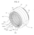
- FIG. 3 is a perspective view illustrating the stator 100 alone of the electric rotating machine 1.
- FIG. 4 is a cross-sectional view corresponding to the inside of individual slots 105.
- the stator 100 includes a stator core (also referred to as a stator iron core) 101 in which a plurality of slots 105 is formed on the inner diameter side of the stator, and three stator windings 102 wounded around the stator core 101, each winding corresponding to U-phase, V-phase, and W-phase, respectively.
- the slots 105 are formed penetratingly in an axial direction and is arranged at equal intervals from each other at a predetermined circumferential pitch in a circumferential direction.
- a slit 109 is opened to extend axially on the inner diameter side.
- Each stator winding 102 includes lots of conductors 106 that are inserted and held in the slots 105, as will be described later.
- the conductors 106 which are provided adjacent to each other in the same slot 105, are welded together at a welding portion 104 formed at one axial end side (lower end side of FIG. 3 ) of the stator core 101.
- a longitudinal stator winding 102 in which the conductors 106 are electrically connected with each other at the welding portion 104 is formed.
- Insulating paper 103 is inserted in each slot 105 to insulate between a linear portion 110 that penetrates through the slot 105 of the conductor 106 and the stator core 101.
- the insulating paper 103 is provided to bundle two adjacent conductors 106 of four conductors 106 arranged in each slot 105. That is, two pieces of insulating paper 103 are provided in each slot 105.
- Each stator winding 102 extends across more than one slots 105 arranged apart from each other at predetermined circumferential pitches by an approximately U-shaped or V-shaped lead-out line portion 107 that is led out from one axial end of the slot 105.
- the stator windings 102 generate a plurality of magnetic poles whose polarity is arranged to alternate in the rotating direction.
- conductors 106a, 106b, 106c, and 106d inserted in the slot 105 are arranged radially in a row in the stator core 101 so as to form concentric layers. It is assumed that the conductors 106a, 106b, 106c, and 106d inserted in each slot 105 are regarded as a first layer, a second layer, a third layer, and a fourth layer, respectively, in this order from the inner diameter side.
- the conductor portion 106a is disposed and inserted in the first layer
- the conductor portion 106b is disposed and inserted in the second layer
- the conductor portion 106c is disposed and inserted in the third layer
- the conductor portion 106d is disposed and inserted in the fourth layer.
- FIG. 5 illustrates the stator core with coils inserted therein when seen from the inner diameter side.
- Each conductor 106 forming the stator winding 102 is a rectangular segment coil having a rectangular cross-section, as is also illustrated in FIGS. 4 and 5 .
- the conductors 106 are shaped substantially similarly, except for the conductors 106 provided at both ends of the stator winding 102 where neutral line portions and output line portions are provided.
- Each conductor 106 has the linear portion 110 axially penetrating through the slot 105, while one lead-out line portion 107 led out from one axial end (left side of FIG. 3 ) of the slot 105 is in the U-shape or the V-shape, and made of a copper wire having joint portions 104 on both ends.
- segment coils may be used.
- coil ends which are located on both axial ends from the ends of the stator core 101, can be formed previously before the segment coil is inserted into the slot 104 to provide an insulating distance appropriate for different phases or the same phase can easily be provided.
- the lead-out line portion 107 of the conductors 106 located at one end of the stator winding 102 includes an output line portion 108 (108U1, 108U2, 108V1, 108V2, 108W1, 108W2) for connecting to external devices, and a neutral line portion 300 to which end portions of each phase are connected.
- the neutral line portions 300a, 300b have a structural feature.
- FIG. 6 illustrates a wire connection structure of the present embodiment.
- the windings are 2Y-connection windings in the present embodiment.
- FIG. 7 is an explanatory view for explaining a neutral line 300a.
- Neutral line portions 300a, 300b are similarly formed, except that one extends from a slot on the external diameter side and the other extends from the inner diameter side.
- the neutral line portion 300a is described as an example.
- the winding forming the coil end 13 (see FIG. 2 ) is not illustrated.
- the neutral line 300a includes a neutral line 301 led out from the first and second slots, and a neutral line 302 led out from the third slot located at an intermediate pitch between the first and second slots.
- the conductors 301 and 302 have a feature that these conductors are led out from the same layer illustrated in FIG. 4 .
- the conductor 301 includes a neutral line of the U-phase winding and a neutral line of the W-phase winding, and is formed by a continuous rectangular conductor. These neutral lines are connected to a neutral line 302 of the V-phase winding.
- the neutral line 301 has an acute-angle axially-folded and bent portion 401, and an axially-bent stepped portion 402 in the vicinity of the acute-angle axially-folded and bent portion.
- the first to third slots for the neutral lines 301 and 302 are arranged at equal pitches.
- Connection portions 303 are connected to extend radially to the stator core 101 in order to restrict the height of the coil end.
- an inclined line portion 111 is formed at the lead-out line portion 107 of all conductors 106 at a portion led out from one axial end of the slot 105.
- the inclined line portion 111 extends circumferentially and is inclined in a predetermined direction from the linear portion 110 penetrating through the slot 105.
- Another inclined line portion is provided at the lead-out line portion 107 of the normal conductor 106 that does not include a neutral line portion 300a.
- the inclined line portion is inclined at an obtuse angle from the inclined line portion 111 and is formed in a U-shape or a V-shape.
- the neutral line 300a has an acute-angle folded portion 401 that turns by more than 90 degrees in the lead-out direction of the inclined line portion 111.
- a folded line portion 402 folded at the folded portion 401 is provided circumferentially in an approximately reverse direction from the inclined line portion 111.
- the neutral line portion 300 also includes a plurality of bent portions that include the axially-bent stepped portion 402 in addition to the acute-angle portion 401 described above. Forming the plurality of bent portions leads to improvement of its rigidity to suppress vibration, and improvement of durability and reliability.
- the neutral line portions 300a, 300b which are not illustrated, are covered by an insulating epoxy-based coating film, such as an epoxy resin. Covering the neutral line portions 300a, 300b with the insulating coating film leads to easily ensuring the insulating characteristic without impairing the cooling characteristic of the conductors.
- connection portions 303 of the neutral lines 301, 302 are connected without removing the insulating coating film, but the insulating coating film may be peeled off to facilitate the connection.
- the connection portions may be peeled off using a mold or by laser, or the insulating coating film may be carbonized by fusing, followed by application of pressure, to thereby indirectly remove the insulating coating film.
- connection portions 302 of the neutral lines 301 and 302 may also be joined and integrated by, for example, brazing, TIG welding, or ultrasonic welding.
- the neutral lines 300 are arranged in the innermost row, as well as the outermost row of the slot, when seen from the radial direction of the stator core 101. In the case of the 1Y-connection or the delta connection, however, the neutral lines 300 may be disposed only in the outermost row or the innermost row.
- FIG. 8 illustrates crawling configuration of the neutral lines and the output lines.
- a W-phase output line 108W2 is made to slip through a space 403 generated under the acute-angle axially-folded and bent portion 401 provided in the neutral line 301, and the axially-bent stepped portion 402 provided in the vicinity of the acute-angle bent portion.
- the neutral lines can restrict the movement of the output lines during assembly, and allow easy positioning without requiring fixing with thread or the like.
- the stepped portion is provided axially in the acute-angle folded portion, and the output line is slipped under the neutral line.
- the interference of the crawling coil can be avoided at the upper portion of the no-connection portion of the U-shaped or V-shaped segment coil, and the low coil end is achieved.
- the stator structure of the electric rotating machine having a feature that the thread or the like is unnecessary for fixing because of the sandwiching structure of the neutral lines sandwiching the output line.
- the present invention is not limited to the aforementioned embodiment, and may include various modifications.
- the embodiment has been described in detail to facilitate the understanding of the present invention, and is not necessarily limited to the embodiment that includes all of the aforementioned structure.
- Other structure may be added to, deleted from, or replaced by a part of the aforementioned embodiment.
Landscapes
- Engineering & Computer Science (AREA)
- Power Engineering (AREA)
- Windings For Motors And Generators (AREA)
- Insulation, Fastening Of Motor, Generator Windings (AREA)
- Manufacture Of Motors, Generators (AREA)
Claims (9)
- Stator einer rotierenden elektrischen Maschine, der Folgendes umfasst:einen Statorkern (101), der mehrere Schlitze (105) enthält,eine Statorwicklung (102), die einen Nullleiter (300a, 300b) und einen Ausgangsleiter (108U1-108W2) enthält, wobeider Nullleiter (300a, 300b) einen Kriechabschnitt aufweist, der sich in einer Umfangsrichtung an einem oberen Abschnitt einer Spule an einem Spulenende (13) erstreckt, und der Nullleiter (300a, 300b) einen in einem spitzen Winkel axial gefalteten, gebogenen Abschnitt (401) aufweist, der um mehr als 90 Grad in der herausführenden Richtung des Nullleiters wendet, wobei der Nullleiter von einem axialen Ende des Schlitzes (105) herausgeführt ist, undder Kriechabschnitt einen axial gebogenen, gestuften Abschnitt (402) aufweist, der in der Umgebung des in einem spitzen Winkel axial gefalteten, gebogenen Abschnitts (401) vorgesehen ist;wobeider Ausgangsleiter (108U1-108W2) unter dem Nullleiter (300a-300b) in der axialen Richtung derart verläuft, dass er unter dem Nullleiter (300a-300b) durch einen Raum (403) gleitet, der unter und zwischen dem in einem spitzen Winkel axial gefalteten, gebogenen Abschnitt (401) und dem axial gebogenen, gestuften Abschnitt (402) gebildet ist, womit eine einbettende Struktur bereitgestellt wird, derart, dass der Nullleiter den Ausgangsleiter einbettet, so dass die Bewegung des Ausgangsleiters während des Zusammenbaus eingeschränkt wird, wobei der Ausgangsleiter (108U1-108W2) angeheftet wird, ohne mit einem Gewinde oder dergleichen befestigt zu werden.
- Stator der rotierenden elektrischen Maschine nach Anspruch 1, wobei
ein 2Y-Verbindungsausgangsleiter aus der innersten Reihe und der äußersten Reihe eines Schlitzes (105) herausgeführt ist. - Stator der rotierenden elektrischen Maschine nach Anspruch 1, wobei
der Ausgangsleiter (108U1-108W2) an mindestens einer Stelle über dem axial gebogenen, gestuften Abschnitt verläuft. - Stator der rotierenden elektrischen Maschine nach Anspruch 1, wobei
der erste und der zweite Schlitz, in die der erste Nullleiter (301) eingeführt ist, und der dritte Schlitz, in den ein zweiter Nullleiter (302) eingeführt ist, als der erste Schlitz, der dritte Schlitz und der zweite Schlitz in dieser Reihenfolge umlaufend angeordnet sind. - Stator der rotierenden elektrischen Maschine nach Anspruch 4, wobei
der erste, der zweite und der dritte Schlitz in gleichen Schlitzabständen angeordnet sind. - Stator der rotierenden elektrischen Maschine nach einem der Ansprüche 4 bis 5, wobei
ein Verbindungsabschnitt (303) des ersten Nullleiters (301) und ein Verbindungsabschnitt (303) des zweiten Nullleiters (302) nebeneinander in der axialen Richtung des Statoreisenkerns (101) angeordnet sind. - Stator der rotierenden elektrischen Maschine nach einem der Ansprüche 4 bis 6, wobei
der isolierende Beschichtungsfilm von den Verbindungsabschnitten (303) des ersten und des zweiten Nullleiters (301, 302) entfernt ist. - Stator der rotierenden elektrischen Maschine nach Anspruch 7, wobei die Verbindungsabschnitte (303) des ersten und des zweiten Nullleiters (301, 302), die miteinander verbunden sind, durch ein Isoliermaterial abgedeckt sind.
- Rotierende elektrische Maschine, die Folgendes umfasst:den Stator (100) der rotierenden elektrischen Maschine nach einem der Ansprüche 1 bis 8; undeinen Rotor (200).
Applications Claiming Priority (2)
| Application Number | Priority Date | Filing Date | Title |
|---|---|---|---|
| JP2013233611 | 2013-11-12 | ||
| PCT/JP2014/077769 WO2015072285A1 (ja) | 2013-11-12 | 2014-10-20 | 固定子及びこれを備えた回転電機 |
Publications (3)
| Publication Number | Publication Date |
|---|---|
| EP3070817A1 EP3070817A1 (de) | 2016-09-21 |
| EP3070817A4 EP3070817A4 (de) | 2017-07-05 |
| EP3070817B1 true EP3070817B1 (de) | 2022-01-05 |
Family
ID=53057227
Family Applications (1)
| Application Number | Title | Priority Date | Filing Date |
|---|---|---|---|
| EP14861800.2A Active EP3070817B1 (de) | 2013-11-12 | 2014-10-20 | Stator und elektrische drehmaschine damit |
Country Status (5)
| Country | Link |
|---|---|
| US (1) | US10916986B2 (de) |
| EP (1) | EP3070817B1 (de) |
| JP (1) | JP6159819B2 (de) |
| CN (2) | CN105706339B (de) |
| WO (1) | WO2015072285A1 (de) |
Families Citing this family (6)
| Publication number | Priority date | Publication date | Assignee | Title |
|---|---|---|---|---|
| CN110546861B (zh) * | 2017-04-19 | 2021-10-26 | Lg麦格纳电子动力总成有限公司 | 旋转电子设备的定子 |
| DE102017208012A1 (de) * | 2017-05-11 | 2018-11-15 | Robert Bosch Gmbh | Stator für eine elektrische Maschine |
| FR3075504B1 (fr) * | 2017-12-20 | 2020-07-17 | Valeo Equipements Electriques Moteur | Stator pour machine electrique tournante |
| JP6729651B2 (ja) | 2018-09-18 | 2020-07-22 | 株式会社富士通ゼネラル | モータ及び圧縮機 |
| FR3101736B1 (fr) * | 2019-10-04 | 2021-10-15 | Valeo Equip Electr Moteur | Bobinage électrique pour une machine électrique tournante |
| JP2022148441A (ja) * | 2021-03-24 | 2022-10-06 | 日本電産株式会社 | ステータ及びステータの製造方法 |
Citations (2)
| Publication number | Priority date | Publication date | Assignee | Title |
|---|---|---|---|---|
| US20030218394A1 (en) * | 2002-05-24 | 2003-11-27 | Mitsubishi Denki Kabushiki Kaisha | Stator for a dynamoelectric machine |
| US20120237372A1 (en) * | 2011-03-15 | 2012-09-20 | Kabushiki Kaisha Toyota Jidoshokki | Motor-driven compressor and wiring method for motor-driven compressor |
Family Cites Families (10)
| Publication number | Priority date | Publication date | Assignee | Title |
|---|---|---|---|---|
| DE2543196A1 (de) * | 1975-09-27 | 1977-04-07 | Bosch Gmbh Robert | Schleifringlose elektrische maschine |
| JP2001231205A (ja) | 2000-02-14 | 2001-08-24 | Mitsubishi Electric Corp | 交流発電機の固定子 |
| JP4453673B2 (ja) | 2006-03-23 | 2010-04-21 | 株式会社デンソー | 回転電機 |
| JP4688003B2 (ja) * | 2007-03-05 | 2011-05-25 | 株式会社デンソー | 回転電機の固定子およびそれを用いた回転電機 |
| US20090140596A1 (en) * | 2007-11-30 | 2009-06-04 | Gm Global Technology Operations, Inc. | Methods and apparatus for a bar-wound stator with parallel connections |
| JP4972570B2 (ja) | 2008-01-31 | 2012-07-11 | 日立オートモティブシステムズ株式会社 | 回転電機の固定子及びその製造方法 |
| JP5070248B2 (ja) * | 2009-06-30 | 2012-11-07 | 日立オートモティブシステムズ株式会社 | 回転電機とその製造方法 |
| JP5768323B2 (ja) | 2010-03-26 | 2015-08-26 | アイシン精機株式会社 | 回転電機のステータ |
| JP2013059156A (ja) * | 2011-09-07 | 2013-03-28 | Hitachi Automotive Systems Ltd | 回転電機の固定子、および回転電機 |
| US20130076170A1 (en) * | 2011-09-27 | 2013-03-28 | Caterpillar Inc. | Stator for electric machine |
-
2014
- 2014-10-20 JP JP2015547704A patent/JP6159819B2/ja active Active
- 2014-10-20 CN CN201480060800.0A patent/CN105706339B/zh active Active
- 2014-10-20 CN CN201910507222.5A patent/CN110086280B/zh active Active
- 2014-10-20 EP EP14861800.2A patent/EP3070817B1/de active Active
- 2014-10-20 WO PCT/JP2014/077769 patent/WO2015072285A1/ja active Application Filing
- 2014-10-20 US US15/033,668 patent/US10916986B2/en active Active
Patent Citations (2)
| Publication number | Priority date | Publication date | Assignee | Title |
|---|---|---|---|---|
| US20030218394A1 (en) * | 2002-05-24 | 2003-11-27 | Mitsubishi Denki Kabushiki Kaisha | Stator for a dynamoelectric machine |
| US20120237372A1 (en) * | 2011-03-15 | 2012-09-20 | Kabushiki Kaisha Toyota Jidoshokki | Motor-driven compressor and wiring method for motor-driven compressor |
Also Published As
| Publication number | Publication date |
|---|---|
| WO2015072285A1 (ja) | 2015-05-21 |
| EP3070817A4 (de) | 2017-07-05 |
| CN105706339A (zh) | 2016-06-22 |
| US20160276890A1 (en) | 2016-09-22 |
| JP6159819B2 (ja) | 2017-07-05 |
| CN110086280B (zh) | 2021-06-25 |
| JPWO2015072285A1 (ja) | 2017-03-16 |
| US10916986B2 (en) | 2021-02-09 |
| EP3070817A1 (de) | 2016-09-21 |
| CN105706339B (zh) | 2019-06-21 |
| CN110086280A (zh) | 2019-08-02 |
Similar Documents
| Publication | Publication Date | Title |
|---|---|---|
| EP3070817B1 (de) | Stator und elektrische drehmaschine damit | |
| JP5237048B2 (ja) | 回転電機、および固定子巻線 | |
| US11387698B2 (en) | Rotating-electrical-machine stator, and rotating electrical machine provided with same | |
| CN109075647B (zh) | 旋转电机 | |
| JP4497008B2 (ja) | 車両用回転電機の固定子 | |
| US20140184011A1 (en) | Stator for Rotating Electrical Machine and Rotating Electrical Machine | |
| EP2913907B1 (de) | Stator für rotierende elektrische maschinen | |
| JP4497102B2 (ja) | 車両用回転電機の固定子 | |
| US20180351427A1 (en) | Stator coil, method for manufacturing stator, and rotating electrical machine | |
| JP5700643B2 (ja) | ブラシレスモータ及びブラシレスモータの駆動方法 | |
| JP5948392B2 (ja) | 回転電機、固定子および固定子巻線 | |
| US11784528B2 (en) | Winding pattern and arrangement for a motor armature | |
| US20050174006A1 (en) | Winding topologies for stators in brushless motors | |
| TW201742356A (zh) | 軸向間隙型旋轉電機 | |
| JP6651426B2 (ja) | 回転電機の固定子、及びこれを備えた回転電機 | |
| WO2022004338A1 (ja) | モータ | |
| JP5909789B2 (ja) | 回転電機、回転電機用ステータおよび車両 | |
| JP5952571B2 (ja) | インシュレータ、及び回転電機 | |
| JP6498775B2 (ja) | 固定子および回転電機 | |
| JP2019071736A (ja) | 回転電機の固定子、および回転電機 | |
| US20230198330A1 (en) | Rotating electric machine | |
| JP2013110889A (ja) | 回転電機のステータの組み付け方法 | |
| JP2012231570A (ja) | 電動機の突極集中巻きステータ |
Legal Events
| Date | Code | Title | Description |
|---|---|---|---|
| PUAI | Public reference made under article 153(3) epc to a published international application that has entered the european phase |
Free format text: ORIGINAL CODE: 0009012 |
|
| 17P | Request for examination filed |
Effective date: 20160613 |
|
| AK | Designated contracting states |
Kind code of ref document: A1 Designated state(s): AL AT BE BG CH CY CZ DE DK EE ES FI FR GB GR HR HU IE IS IT LI LT LU LV MC MK MT NL NO PL PT RO RS SE SI SK SM TR |
|
| AX | Request for extension of the european patent |
Extension state: BA ME |
|
| DAX | Request for extension of the european patent (deleted) | ||
| A4 | Supplementary search report drawn up and despatched |
Effective date: 20170606 |
|
| RIC1 | Information provided on ipc code assigned before grant |
Ipc: H02K 3/04 20060101AFI20170529BHEP Ipc: H02K 3/12 20060101ALN20170529BHEP Ipc: H02K 3/28 20060101ALN20170529BHEP Ipc: H02K 15/00 20060101ALI20170529BHEP Ipc: H02K 3/50 20060101ALI20170529BHEP |
|
| STAA | Information on the status of an ep patent application or granted ep patent |
Free format text: STATUS: EXAMINATION IS IN PROGRESS |
|
| 17Q | First examination report despatched |
Effective date: 20190719 |
|
| STAA | Information on the status of an ep patent application or granted ep patent |
Free format text: STATUS: EXAMINATION IS IN PROGRESS |
|
| GRAJ | Information related to disapproval of communication of intention to grant by the applicant or resumption of examination proceedings by the epo deleted |
Free format text: ORIGINAL CODE: EPIDOSDIGR1 |
|
| GRAP | Despatch of communication of intention to grant a patent |
Free format text: ORIGINAL CODE: EPIDOSNIGR1 |
|
| RIC1 | Information provided on ipc code assigned before grant |
Ipc: H02K 3/28 20060101ALN20210630BHEP Ipc: H02K 3/12 20060101ALN20210630BHEP Ipc: H02K 15/00 20060101ALI20210630BHEP Ipc: H02K 3/50 20060101ALI20210630BHEP Ipc: H02K 3/04 20060101AFI20210630BHEP |
|
| RIC1 | Information provided on ipc code assigned before grant |
Ipc: H02K 3/28 20060101ALN20210705BHEP Ipc: H02K 3/12 20060101ALN20210705BHEP Ipc: H02K 15/00 20060101ALI20210705BHEP Ipc: H02K 3/50 20060101ALI20210705BHEP Ipc: H02K 3/04 20060101AFI20210705BHEP |
|
| RIC1 | Information provided on ipc code assigned before grant |
Ipc: H02K 3/28 20060101ALN20210721BHEP Ipc: H02K 3/12 20060101ALN20210721BHEP Ipc: H02K 15/00 20060101ALI20210721BHEP Ipc: H02K 3/50 20060101ALI20210721BHEP Ipc: H02K 3/04 20060101AFI20210721BHEP |
|
| GRAP | Despatch of communication of intention to grant a patent |
Free format text: ORIGINAL CODE: EPIDOSNIGR1 |
|
| STAA | Information on the status of an ep patent application or granted ep patent |
Free format text: STATUS: GRANT OF PATENT IS INTENDED |
|
| RAP3 | Party data changed (applicant data changed or rights of an application transferred) |
Owner name: HITACHI ASTEMO, LTD. |
|
| INTG | Intention to grant announced |
Effective date: 20210914 |
|
| GRAS | Grant fee paid |
Free format text: ORIGINAL CODE: EPIDOSNIGR3 |
|
| GRAA | (expected) grant |
Free format text: ORIGINAL CODE: 0009210 |
|
| STAA | Information on the status of an ep patent application or granted ep patent |
Free format text: STATUS: THE PATENT HAS BEEN GRANTED |
|
| AK | Designated contracting states |
Kind code of ref document: B1 Designated state(s): AL AT BE BG CH CY CZ DE DK EE ES FI FR GB GR HR HU IE IS IT LI LT LU LV MC MK MT NL NO PL PT RO RS SE SI SK SM TR |
|
| REG | Reference to a national code |
Ref country code: GB Ref legal event code: FG4D |
|
| REG | Reference to a national code |
Ref country code: CH Ref legal event code: EP |
|
| REG | Reference to a national code |
Ref country code: AT Ref legal event code: REF Ref document number: 1461464 Country of ref document: AT Kind code of ref document: T Effective date: 20220115 |
|
| REG | Reference to a national code |
Ref country code: DE Ref legal event code: R096 Ref document number: 602014082084 Country of ref document: DE |
|
| REG | Reference to a national code |
Ref country code: IE Ref legal event code: FG4D |
|
| REG | Reference to a national code |
Ref country code: LT Ref legal event code: MG9D |
|
| REG | Reference to a national code |
Ref country code: NL Ref legal event code: MP Effective date: 20220105 |
|
| REG | Reference to a national code |
Ref country code: AT Ref legal event code: MK05 Ref document number: 1461464 Country of ref document: AT Kind code of ref document: T Effective date: 20220105 |
|
| PG25 | Lapsed in a contracting state [announced via postgrant information from national office to epo] |
Ref country code: NL Free format text: LAPSE BECAUSE OF FAILURE TO SUBMIT A TRANSLATION OF THE DESCRIPTION OR TO PAY THE FEE WITHIN THE PRESCRIBED TIME-LIMIT Effective date: 20220105 |
|
| PG25 | Lapsed in a contracting state [announced via postgrant information from national office to epo] |
Ref country code: SE Free format text: LAPSE BECAUSE OF FAILURE TO SUBMIT A TRANSLATION OF THE DESCRIPTION OR TO PAY THE FEE WITHIN THE PRESCRIBED TIME-LIMIT Effective date: 20220105 Ref country code: RS Free format text: LAPSE BECAUSE OF FAILURE TO SUBMIT A TRANSLATION OF THE DESCRIPTION OR TO PAY THE FEE WITHIN THE PRESCRIBED TIME-LIMIT Effective date: 20220105 Ref country code: PT Free format text: LAPSE BECAUSE OF FAILURE TO SUBMIT A TRANSLATION OF THE DESCRIPTION OR TO PAY THE FEE WITHIN THE PRESCRIBED TIME-LIMIT Effective date: 20220505 Ref country code: NO Free format text: LAPSE BECAUSE OF FAILURE TO SUBMIT A TRANSLATION OF THE DESCRIPTION OR TO PAY THE FEE WITHIN THE PRESCRIBED TIME-LIMIT Effective date: 20220405 Ref country code: LT Free format text: LAPSE BECAUSE OF FAILURE TO SUBMIT A TRANSLATION OF THE DESCRIPTION OR TO PAY THE FEE WITHIN THE PRESCRIBED TIME-LIMIT Effective date: 20220105 Ref country code: HR Free format text: LAPSE BECAUSE OF FAILURE TO SUBMIT A TRANSLATION OF THE DESCRIPTION OR TO PAY THE FEE WITHIN THE PRESCRIBED TIME-LIMIT Effective date: 20220105 Ref country code: ES Free format text: LAPSE BECAUSE OF FAILURE TO SUBMIT A TRANSLATION OF THE DESCRIPTION OR TO PAY THE FEE WITHIN THE PRESCRIBED TIME-LIMIT Effective date: 20220105 Ref country code: BG Free format text: LAPSE BECAUSE OF FAILURE TO SUBMIT A TRANSLATION OF THE DESCRIPTION OR TO PAY THE FEE WITHIN THE PRESCRIBED TIME-LIMIT Effective date: 20220405 |
|
| PG25 | Lapsed in a contracting state [announced via postgrant information from national office to epo] |
Ref country code: PL Free format text: LAPSE BECAUSE OF FAILURE TO SUBMIT A TRANSLATION OF THE DESCRIPTION OR TO PAY THE FEE WITHIN THE PRESCRIBED TIME-LIMIT Effective date: 20220105 Ref country code: LV Free format text: LAPSE BECAUSE OF FAILURE TO SUBMIT A TRANSLATION OF THE DESCRIPTION OR TO PAY THE FEE WITHIN THE PRESCRIBED TIME-LIMIT Effective date: 20220105 Ref country code: GR Free format text: LAPSE BECAUSE OF FAILURE TO SUBMIT A TRANSLATION OF THE DESCRIPTION OR TO PAY THE FEE WITHIN THE PRESCRIBED TIME-LIMIT Effective date: 20220406 Ref country code: FI Free format text: LAPSE BECAUSE OF FAILURE TO SUBMIT A TRANSLATION OF THE DESCRIPTION OR TO PAY THE FEE WITHIN THE PRESCRIBED TIME-LIMIT Effective date: 20220105 Ref country code: AT Free format text: LAPSE BECAUSE OF FAILURE TO SUBMIT A TRANSLATION OF THE DESCRIPTION OR TO PAY THE FEE WITHIN THE PRESCRIBED TIME-LIMIT Effective date: 20220105 |
|
| PG25 | Lapsed in a contracting state [announced via postgrant information from national office to epo] |
Ref country code: IS Free format text: LAPSE BECAUSE OF FAILURE TO SUBMIT A TRANSLATION OF THE DESCRIPTION OR TO PAY THE FEE WITHIN THE PRESCRIBED TIME-LIMIT Effective date: 20220505 |
|
| REG | Reference to a national code |
Ref country code: DE Ref legal event code: R097 Ref document number: 602014082084 Country of ref document: DE |
|
| PG25 | Lapsed in a contracting state [announced via postgrant information from national office to epo] |
Ref country code: SM Free format text: LAPSE BECAUSE OF FAILURE TO SUBMIT A TRANSLATION OF THE DESCRIPTION OR TO PAY THE FEE WITHIN THE PRESCRIBED TIME-LIMIT Effective date: 20220105 Ref country code: SK Free format text: LAPSE BECAUSE OF FAILURE TO SUBMIT A TRANSLATION OF THE DESCRIPTION OR TO PAY THE FEE WITHIN THE PRESCRIBED TIME-LIMIT Effective date: 20220105 Ref country code: RO Free format text: LAPSE BECAUSE OF FAILURE TO SUBMIT A TRANSLATION OF THE DESCRIPTION OR TO PAY THE FEE WITHIN THE PRESCRIBED TIME-LIMIT Effective date: 20220105 Ref country code: EE Free format text: LAPSE BECAUSE OF FAILURE TO SUBMIT A TRANSLATION OF THE DESCRIPTION OR TO PAY THE FEE WITHIN THE PRESCRIBED TIME-LIMIT Effective date: 20220105 Ref country code: DK Free format text: LAPSE BECAUSE OF FAILURE TO SUBMIT A TRANSLATION OF THE DESCRIPTION OR TO PAY THE FEE WITHIN THE PRESCRIBED TIME-LIMIT Effective date: 20220105 Ref country code: CZ Free format text: LAPSE BECAUSE OF FAILURE TO SUBMIT A TRANSLATION OF THE DESCRIPTION OR TO PAY THE FEE WITHIN THE PRESCRIBED TIME-LIMIT Effective date: 20220105 |
|
| PLBE | No opposition filed within time limit |
Free format text: ORIGINAL CODE: 0009261 |
|
| STAA | Information on the status of an ep patent application or granted ep patent |
Free format text: STATUS: NO OPPOSITION FILED WITHIN TIME LIMIT |
|
| PG25 | Lapsed in a contracting state [announced via postgrant information from national office to epo] |
Ref country code: AL Free format text: LAPSE BECAUSE OF FAILURE TO SUBMIT A TRANSLATION OF THE DESCRIPTION OR TO PAY THE FEE WITHIN THE PRESCRIBED TIME-LIMIT Effective date: 20220105 |
|
| 26N | No opposition filed |
Effective date: 20221006 |
|
| PG25 | Lapsed in a contracting state [announced via postgrant information from national office to epo] |
Ref country code: SI Free format text: LAPSE BECAUSE OF FAILURE TO SUBMIT A TRANSLATION OF THE DESCRIPTION OR TO PAY THE FEE WITHIN THE PRESCRIBED TIME-LIMIT Effective date: 20220105 |
|
| PG25 | Lapsed in a contracting state [announced via postgrant information from national office to epo] |
Ref country code: MC Free format text: LAPSE BECAUSE OF FAILURE TO SUBMIT A TRANSLATION OF THE DESCRIPTION OR TO PAY THE FEE WITHIN THE PRESCRIBED TIME-LIMIT Effective date: 20220105 |
|
| REG | Reference to a national code |
Ref country code: CH Ref legal event code: PL |
|
| REG | Reference to a national code |
Ref country code: BE Ref legal event code: MM Effective date: 20221031 |
|
| GBPC | Gb: european patent ceased through non-payment of renewal fee |
Effective date: 20221020 |
|
| PG25 | Lapsed in a contracting state [announced via postgrant information from national office to epo] |
Ref country code: LU Free format text: LAPSE BECAUSE OF NON-PAYMENT OF DUE FEES Effective date: 20221020 |
|
| PG25 | Lapsed in a contracting state [announced via postgrant information from national office to epo] |
Ref country code: LI Free format text: LAPSE BECAUSE OF NON-PAYMENT OF DUE FEES Effective date: 20221031 Ref country code: IT Free format text: LAPSE BECAUSE OF FAILURE TO SUBMIT A TRANSLATION OF THE DESCRIPTION OR TO PAY THE FEE WITHIN THE PRESCRIBED TIME-LIMIT Effective date: 20220105 Ref country code: FR Free format text: LAPSE BECAUSE OF NON-PAYMENT OF DUE FEES Effective date: 20221031 Ref country code: CH Free format text: LAPSE BECAUSE OF NON-PAYMENT OF DUE FEES Effective date: 20221031 |
|
| PG25 | Lapsed in a contracting state [announced via postgrant information from national office to epo] |
Ref country code: BE Free format text: LAPSE BECAUSE OF NON-PAYMENT OF DUE FEES Effective date: 20221031 |
|
| PG25 | Lapsed in a contracting state [announced via postgrant information from national office to epo] |
Ref country code: IE Free format text: LAPSE BECAUSE OF NON-PAYMENT OF DUE FEES Effective date: 20221020 Ref country code: GB Free format text: LAPSE BECAUSE OF NON-PAYMENT OF DUE FEES Effective date: 20221020 |
|
| PGFP | Annual fee paid to national office [announced via postgrant information from national office to epo] |
Ref country code: DE Payment date: 20230830 Year of fee payment: 10 |
|
| PG25 | Lapsed in a contracting state [announced via postgrant information from national office to epo] |
Ref country code: HU Free format text: LAPSE BECAUSE OF FAILURE TO SUBMIT A TRANSLATION OF THE DESCRIPTION OR TO PAY THE FEE WITHIN THE PRESCRIBED TIME-LIMIT; INVALID AB INITIO Effective date: 20141020 |
|
| PG25 | Lapsed in a contracting state [announced via postgrant information from national office to epo] |
Ref country code: CY Free format text: LAPSE BECAUSE OF FAILURE TO SUBMIT A TRANSLATION OF THE DESCRIPTION OR TO PAY THE FEE WITHIN THE PRESCRIBED TIME-LIMIT Effective date: 20220105 |
|
| PG25 | Lapsed in a contracting state [announced via postgrant information from national office to epo] |
Ref country code: MK Free format text: LAPSE BECAUSE OF FAILURE TO SUBMIT A TRANSLATION OF THE DESCRIPTION OR TO PAY THE FEE WITHIN THE PRESCRIBED TIME-LIMIT Effective date: 20220105 |
|
| PG25 | Lapsed in a contracting state [announced via postgrant information from national office to epo] |
Ref country code: TR Free format text: LAPSE BECAUSE OF FAILURE TO SUBMIT A TRANSLATION OF THE DESCRIPTION OR TO PAY THE FEE WITHIN THE PRESCRIBED TIME-LIMIT Effective date: 20220105 |