EP3069933A2 - Kraftfahrzeug mit optischer anzeige für den aussenbereich - Google Patents
Kraftfahrzeug mit optischer anzeige für den aussenbereich Download PDFInfo
- Publication number
- EP3069933A2 EP3069933A2 EP16000534.4A EP16000534A EP3069933A2 EP 3069933 A2 EP3069933 A2 EP 3069933A2 EP 16000534 A EP16000534 A EP 16000534A EP 3069933 A2 EP3069933 A2 EP 3069933A2
- Authority
- EP
- European Patent Office
- Prior art keywords
- motor vehicle
- light
- message
- light field
- projection element
- Prior art date
- Legal status (The legal status is an assumption and is not a legal conclusion. Google has not performed a legal analysis and makes no representation as to the accuracy of the status listed.)
- Granted
Links
- 230000003287 optical effect Effects 0.000 title claims abstract description 30
- 239000007787 solid Substances 0.000 claims abstract description 9
- 238000000034 method Methods 0.000 claims description 6
- 230000001953 sensory effect Effects 0.000 abstract 1
- 238000011161 development Methods 0.000 description 12
- 230000018109 developmental process Effects 0.000 description 12
- 230000008901 benefit Effects 0.000 description 9
- 238000013459 approach Methods 0.000 description 4
- 230000001419 dependent effect Effects 0.000 description 4
- 238000004891 communication Methods 0.000 description 2
- 235000004522 Pentaglottis sempervirens Nutrition 0.000 description 1
- 206010039203 Road traffic accident Diseases 0.000 description 1
- 230000001154 acute effect Effects 0.000 description 1
- 230000008878 coupling Effects 0.000 description 1
- 238000010168 coupling process Methods 0.000 description 1
- 238000005859 coupling reaction Methods 0.000 description 1
- 238000006073 displacement reaction Methods 0.000 description 1
- 230000000694 effects Effects 0.000 description 1
- 239000011521 glass Substances 0.000 description 1
- 239000000463 material Substances 0.000 description 1
- 230000007704 transition Effects 0.000 description 1
- 230000000007 visual effect Effects 0.000 description 1
Images


Classifications
-
- G—PHYSICS
- G03—PHOTOGRAPHY; CINEMATOGRAPHY; ANALOGOUS TECHNIQUES USING WAVES OTHER THAN OPTICAL WAVES; ELECTROGRAPHY; HOLOGRAPHY
- G03H—HOLOGRAPHIC PROCESSES OR APPARATUS
- G03H1/00—Holographic processes or apparatus using light, infrared or ultraviolet waves for obtaining holograms or for obtaining an image from them; Details peculiar thereto
- G03H1/22—Processes or apparatus for obtaining an optical image from holograms
- G03H1/2249—Holobject properties
-
- B—PERFORMING OPERATIONS; TRANSPORTING
- B60—VEHICLES IN GENERAL
- B60Q—ARRANGEMENT OF SIGNALLING OR LIGHTING DEVICES, THE MOUNTING OR SUPPORTING THEREOF OR CIRCUITS THEREFOR, FOR VEHICLES IN GENERAL
- B60Q1/00—Arrangement of optical signalling or lighting devices, the mounting or supporting thereof or circuits therefor
- B60Q1/26—Arrangement of optical signalling or lighting devices, the mounting or supporting thereof or circuits therefor the devices being primarily intended to indicate the vehicle, or parts thereof, or to give signals, to other traffic
- B60Q1/50—Arrangement of optical signalling or lighting devices, the mounting or supporting thereof or circuits therefor the devices being primarily intended to indicate the vehicle, or parts thereof, or to give signals, to other traffic for indicating other intentions or conditions, e.g. request for waiting or overtaking
- B60Q1/525—Arrangement of optical signalling or lighting devices, the mounting or supporting thereof or circuits therefor the devices being primarily intended to indicate the vehicle, or parts thereof, or to give signals, to other traffic for indicating other intentions or conditions, e.g. request for waiting or overtaking automatically indicating risk of collision between vehicles in traffic or with pedestrians, e.g. after risk assessment using the vehicle sensor data
- B60Q1/535—Arrangement of optical signalling or lighting devices, the mounting or supporting thereof or circuits therefor the devices being primarily intended to indicate the vehicle, or parts thereof, or to give signals, to other traffic for indicating other intentions or conditions, e.g. request for waiting or overtaking automatically indicating risk of collision between vehicles in traffic or with pedestrians, e.g. after risk assessment using the vehicle sensor data to prevent rear-end collisions, e.g. by indicating safety distance at the rear of the vehicle
-
- G—PHYSICS
- G03—PHOTOGRAPHY; CINEMATOGRAPHY; ANALOGOUS TECHNIQUES USING WAVES OTHER THAN OPTICAL WAVES; ELECTROGRAPHY; HOLOGRAPHY
- G03H—HOLOGRAPHIC PROCESSES OR APPARATUS
- G03H1/00—Holographic processes or apparatus using light, infrared or ultraviolet waves for obtaining holograms or for obtaining an image from them; Details peculiar thereto
- G03H1/22—Processes or apparatus for obtaining an optical image from holograms
- G03H1/2202—Reconstruction geometries or arrangements
- G03H2001/2236—Details of the viewing window
-
- G—PHYSICS
- G03—PHOTOGRAPHY; CINEMATOGRAPHY; ANALOGOUS TECHNIQUES USING WAVES OTHER THAN OPTICAL WAVES; ELECTROGRAPHY; HOLOGRAPHY
- G03H—HOLOGRAPHIC PROCESSES OR APPARATUS
- G03H2226/00—Electro-optic or electronic components relating to digital holography
- G03H2226/05—Means for tracking the observer
-
- G—PHYSICS
- G03—PHOTOGRAPHY; CINEMATOGRAPHY; ANALOGOUS TECHNIQUES USING WAVES OTHER THAN OPTICAL WAVES; ELECTROGRAPHY; HOLOGRAPHY
- G03H—HOLOGRAPHIC PROCESSES OR APPARATUS
- G03H2227/00—Mechanical components or mechanical aspects not otherwise provided for
- G03H2227/03—Means for moving one component
-
- G—PHYSICS
- G03—PHOTOGRAPHY; CINEMATOGRAPHY; ANALOGOUS TECHNIQUES USING WAVES OTHER THAN OPTICAL WAVES; ELECTROGRAPHY; HOLOGRAPHY
- G03H—HOLOGRAPHIC PROCESSES OR APPARATUS
- G03H2227/00—Mechanical components or mechanical aspects not otherwise provided for
- G03H2227/05—Support holding the holographic record
- G03H2227/06—Support including light source
Definitions
- the invention relates to a motor vehicle with a display device which is self-luminous, that is to say has a light source.
- the display device is designed to display an optical message in an exterior area of the motor vehicle. In other words, the message is visible from outside the motor vehicle.
- message is meant in the context of the invention, a hint text or a graphic symbol.
- the invention also includes a method for generating the optical message.
- the invention comprises a motor vehicle with a display device which has a light source and which is designed to display an optical message in an outer region of the motor vehicle.
- An optical message is understood to mean, in particular, an information text and / or a graphic symbol.
- the optical message is a light signal.
- the light source is designed to project light onto a projection element of the display device.
- the projection element is designed to generate from the light a light field representing the message.
- the projection element can for example be transilluminated by the light or be illuminated by the light and form the light field by reflection.
- the light field is the area in which the light emitted by the projection element is visible.
- the display device has a limiting device which is designed to limit the light field in the outside to a predetermined solid angle range.
- the light field is radiated from the projection element only in a predetermined solid angle range.
- Such a limited solid angle range is also referred to as eyebox.
- a viewer can therefore only recognize the optical message visible on the projection element if it is within the solid angle range, ie. in the eyebox is.
- the optical message is displayed only to this viewer without a sensor.
- the invention has further developments, resulting in additional benefits.
- the display device is designed to emit the light field in a rear area of the motor vehicle which is adjacent to a rear end of the motor vehicle. This results in the advantage that the optical message can only be seen from the following motor vehicle. In other words, the light field is limited by the limiting device to the rear region of the motor vehicle.
- an upper limit of the light field, starting from the motor vehicle, is directed obliquely downward, so that a viewer only sees the message at a given eye height if he has a predetermined minimum distance from the motor vehicle.
- an azimuth opening angle of the light field is less than 20 degrees, in particular less than 10 degrees.
- the light field is aligned in the outer region along a strip extending in the vehicle longitudinal direction behind a driver's seat of the motor vehicle.
- the optical message is provided according to a development that the limiting device has lamellae and / or a collimator.
- the limiting device has lamellae and / or a collimator.
- stray light emanating from the projection element can be absorbed.
- the fins and / or the collimator may extend along a light emitting surface to form light channels whose channel walls absorb scattered light.
- the projection element and the limiting device are formed by a holographic optical element (HOE).
- HOE holographic optical element
- the optical message is displayed as a hologram.
- a holographic optical element has the advantage that the projection element and the limiting device are formed by one and the same arrangement of a holographic image or film material or a holographic plate.
- a hologram has the advantage that a sharply delimited light field is generated, that is, a transition from the light field to a light-free area in the region of the boundary of the light field is particularly narrow.
- a pivoting device which is designed to set a respective angle of inclination of the projection element and / or the limiting device as a function of an operating parameter of the motor vehicle.
- the operating parameter is, according to one embodiment, a driving speed of the motor vehicle.
- the driving speed can be determined, for example, via a communication bus of the motor vehicle, for example a CAN bus (CAN controller area network), by the display device.
- a communication bus of the motor vehicle for example a CAN bus (CAN controller area network)
- CAN controller area network CAN controller area network
- the pivoting device is designed to set the respective inclination angle as a function of a pitch angle of the motor vehicle.
- the pitch angle of the motor vehicle can be determined, for example, by a sensor of an ESP (electronic stability program) of the motor vehicle.
- the adjustment of the inclination angle as a function of the pitch angle has the advantage that a boundary of the light field in the outer area does not fluctuate when the motor vehicle travels over an uneven driving surface. In other words pitch movements of the motor vehicle are compensated by the pivoting device.
- the motor vehicle according to the invention is preferably designed as a motor vehicle, in particular as a passenger car.
- the invention also includes a method for displaying an optical message in an exterior area of the motor vehicle.
- a light source Light is projected onto a projection element.
- the projection element generates from the light a light field representing the message.
- the optical message is visible from outside the motor vehicle, without a projection surface outside the motor vehicle is necessary.
- the message can thus be focused directly with the eye.
- the light field is limited to a predetermined solid angle range in the outer area by a limiting device. This results in the advantage that visibility of the message is dependent on a relative position of a viewer to the motor vehicle.
- the invention also includes further developments of the method according to the invention, which have features which have already been described in connection with the developments of the motor vehicle according to the invention. For this reason, the corresponding developments of the method according to the invention are not described again here.
- the exemplary embodiment explained below is a preferred embodiment of the invention.
- the described components of the embodiment each represent individual features of the invention that are to be considered independently of one another, which also each independently further develop the invention and thus also individually or in a different combination than the one shown as part of the invention.
- the described embodiment can also be supplemented by further features of the invention already described.
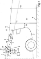
- Fig. 1 is shown by a motor vehicle 1 a tail 2.
- the motor vehicle 1 may be a motor vehicle, in particular a passenger car.
- the motor vehicle 1 has a display device 3, which has a light source 4 and a projection element 5.
- the light source 4 may be, for example, a laser light source.
- the light source 4 generates light 6, which can optionally be expanded by an optical system 7, for example a lens.
- the light 6 is projected onto the projection element 5.
- the projection element 5 can be transparent, for example.
- the display device 3 furthermore has a limiting device 8. By the limiting device 8, an outgoing from the projection element 5 light field 9 is limited. As a result, an upper limit 10 and optionally a lower limit 11 of the light field 9 are set in an outer region 12 of the motor vehicle 1.
- the light field 9 represents a message M.
- the message M is visible only in a rear region 13 behind the rear 2 of the motor vehicle 1 due to the emission direction of the light field 9.
- the upper limit 10 is directed starting from the projection element 5 obliquely downwards.
- the upper limit 10 includes a driving surface R an acute angle, which is preferably greater than 10 °, in particular greater than 20 °.
- the eye height 14 may, for example, be related to the driving surface R.
- the limiting device 8 may be provided, for example, by fins or a collimator.
- the projection element 5 can then be, for example, a TFT (TFT) display or a transparent, colored element, for example made of glass or plastic.
- TFT TFT
- the projection element 5 and the limiting device 8 can also together by a holographic optical Be provided element.
- the message M represents a hologram in this case.
- the projection element 5 and / or the limiting device 8 can be designed to be pivotable, for example, by being rotatably mounted about an axis of rotation 16.
- a pivoting device 17 may be designed to adjust an inclination angle 19 of the projection element 5 and / or the limiting device 8 about the axis of rotation 16 as a function of an operating parameter 18 of the motor vehicle 1.
- the pivoting device 17 can generate, for example via a mechanical coupling element 20, a displacement movement or pivoting movement 21 of the projection element 5 and / or the limiting device 8.
- the operating parameter 18 may be, for example, the current driving speed of the motor vehicle 1 and / or a pitch angle of the motor vehicle 1.
- the operating parameter 18 can be transmitted, for example, via a communication bus 22 of the motor vehicle 1 from a sensor device 23 of the motor vehicle 1 to the pivoting device 17.
- the sensor device 23 may be, for example, an ESP (electronic stability program) and / or a tachometer of the motor vehicle 1.
- Fig. 2 and Fig. 3 which effect is achieved with the display device 3 of the motor vehicle 1.
- a driving situation 24 shown in which behind the motor vehicle 1 a foreign vehicle 25 ascends on the motor vehicle 1, that is, the power vehicle 1 approaches.
- Fig. 3 the driving situation 24 is shown, wherein the driver 26 has so far approximated with the other vehicle 25 to the rear 2 of the motor vehicle 1, that its distance is equal to or smaller than the minimum distance 15. In other words, the eyes of the driver 26 are in the light field 9. Therefore, in the field of view of the driver 26, the message M is visible.
- Fig. 4 is the driving situation 24 from a bird's eye view, that is from above, shown.
- a passenger 27 can sit.
- An azimuth angle 28 included by a right boundary 29 and a left boundary 30 of the light field 9 may be set to detect only the driver 26, not the passenger 27.
- the light field 9 may be limited in the rear region 13 to a strip 31 which extends in the vehicle longitudinal direction 32 behind a driver's seat 33 of the motor vehicle 1 or extending.
- the light field is thus limited in the vertical direction to a predetermined solid angle range W.
- the passenger 27 is not irritated or confused by the message.
- Dense driving is often the cause of serious traffic accidents.
- a holographic object with a message M in the rear area 13 in the room is shown in the motor vehicle 1. This appears for the driver 26 only from a defined minimum distance 15 from the rear 2 of the motor vehicle 1.
- the message M appears only when too tight approach.
- the display device 3 it is possible to give a hint to a following vehicle to maintain the distance, without disturbing other road users.
- the function can be controlled speed-dependent by the arrangement is readjusted mechanically.
- the laser beam with the light 6 can first be widened by an optical system 7 or also be radiated directly to the holographic optical element, which can be formed from the projection element 5 and the limiting device 8, through the rear window or the tail light of the motor vehicle 1 to the rear.
- the example shows how the invention can provide a holographic alert for approaching vehicles through a holographic optical element (HOE).
- HOE holographic optical element
Abstract
Description
- Die Erfindung betrifft ein Kraftfahrzeug mit einer Anzeigeeinrichtung, die selbstleuchtend ist, das heißt eine Lichtquelle aufweist. Die Anzeigeeinrichtung ist dazu ausgelegt, in einem Außenbereich des Kraftfahrzeugs eine optische Nachricht anzuzeigen. Mit anderen Worten ist die Nachricht von außerhalb des Kraftfahrzeugs sichtbar. Unter Nachricht ist im Zusammenhang mit der Erfindung ein Hinweistext oder ein graphisches Symbol zu verstehen. Zu der Erfindung gehört auch ein Verfahren zum Erzeugen der optischen Nachricht.
- Aus der
DE 10 2012 011 087 A1 ist hierzu bekannt, als optische Nachricht eine Abstandswarnung an einem Heck des Kraftfahrzeugs anzuzeigen, wenn ein nachfolgendes Fahrzeug zu dicht auffährt. Um einen Zeitpunkt zu bestimmen, zu welchem die Anzeigeeinrichtung aktiviert werden soll, müssen ein Abstand und eine Relativgeschwindigkeit des nachfolgenden Fahrzeugs gemessen werden. Hierzu ist eine entsprechend aufwendige Sensorik nötig. - Aus der
DE 10 2004 025 251 A1 ist bekannt, in einem Kraftfahrzeug zum Erzeugen einer Nachricht einen Lichtstrahl zu erzeugen, der auf eine reflektierende Fläche auf der Heckscheibe des Kraftfahrzeugs projiziert wird und hier eine Signalinformation für einen Fahrer eines anderen Kraftfahrzeugs sichtbar macht. Beispielsweise kann hierdurch in der Heckscheibe des Kraftfahrzeugs ein Warndreieck angezeigt werden. - Aus der
US 2004/0041983 A1 ist bekannt, mittels eines Lasers ein Warndreieck auf eine Straße zu projizieren. Falls ein solches Kraftfahrzeug durch Nebel fährt, kann das Warndreieck auch in den Nebel hinein projiziert werden. Dieses Verfahren benötigt stets eine außerhalb des Kraftfahrzeugs befindliche Projektionsfläche, um die optische Nachricht sichtbar zu machen. Der Erfindung liegt die Aufgabe zugrunde, mit geringem schaltungstechnischen Aufwand eine optische Nachricht in einem Außenbereich des Kraftfahrzeugs anzuzeigen, falls ein Betrachter im Außenbereich ein vorbestimmtes Abstandskriterium erfüllt. - Die Aufgabe wird durch die Gegenstände der unabhängigen Patentansprüche gelöst. Vorteilhafte Weiterbildungen der Erfindung sind durch die Merkmale der abhängigen Patentansprüche gegeben.
- Die Erfindung umfasst ein Kraftfahrzeug mit einer Anzeigeeinrichtung, die eine Lichtquelle aufweist und die dazu ausgelegt ist, in einem Außenbereich des Kraftfahrzeugs eine optische Nachricht anzuzeigen. Unter einer optischen Nachricht werden insbesondere ein Hinweistext und/oder ein graphisches Symbol verstanden. Die optische Nachricht ist dabei ein Lichtsignal.
- Die Lichtquelle ist dazu ausgelegt, Licht auf ein Projektionselement der Anzeigeeinrichtung zu projizieren. Mit anderen Worten ist keine Projektionsfläche außerhalb des Kraftfahrzeugs nötig. Das Projektionselement ist dazu ausgelegt, aus dem Licht ein die Nachricht darstellendes Lichtfeld zu erzeugen. Hierzu kann das Projektionselement beispielsweise von dem Licht durchleuchtet werden oder von dem Licht angestrahlt werden und durch Reflexion das Lichtfeld bilden. Das Lichtfeld ist derjenige Bereich, in welchem das von dem Projektionselement abgestrahlte Licht sichtbar ist.
- Um nun die optische Nachricht nur für solche Betrachter sichtbar zu machen, die sich in einem bestimmten Teil des Außenbereichs des Kraftfahrzeugs befinden, weist die Anzeigeeinrichtung eine Begrenzungseinrichtung auf, die dazu ausgelegt ist, das Lichtfeld im Außenbereich auf einen vorbestimmten Raumwinkelbereich zu begrenzen. Mit anderen Worten wird das Lichtfeld ausgehend von dem Projektionselement nur in einen vorbestimmten Raumwinkelbereich abgestrahlt. Ein solcher begrenzter Raumwinkelbereich wird auch als Eyebox bezeichnet. Ein Betrachter kann also die auf dem Projektionselement sichtbare optische Nachricht nur dann erkennen, wenn er innerhalb des Raumwinkelbereichs steht, d.h. in der Eyebox ist. In vorteilhafter Weise wird so ohne eine Sensorik die optische Nachricht nur diesem Betrachter angezeigt.
- Die Erfindung weist Weiterbildungen auf, durch die sich zusätzliche Vorteile ergeben.
- Gemäß einer Weiterbildung ist die Anzeigeeinrichtung dazu ausgelegt, das Lichtfeld in einen an ein Heck des Kraftfahrzeugs angrenzenden rückwärtigen Bereich des Kraftfahrzeugs abzustrahlen. Hierdurch ergibt sich der Vorteil, dass die optische Nachricht nur vom nachfolgenden Kraftfahrzeug aus gesehen werden kann. Mit anderen Worten ist das Lichtfeld durch die Begrenzungseinrichtung auf den rückwärtigen Bereich des Kraftfahrzeugs begrenzt.
- Gemäß einer Weiterbildung ist eine obere Grenze des Lichtfelds ausgehend vom Kraftfahrzeug schräg nach unten gerichtet, sodass ein Betrachter bei einer gegebenen Augenhöhe die Nachricht nur sieht, falls er einen vorbestimmten Mindestabstand vom Kraftfahrzeug aufweist. Hierdurch ergibt sich der Vorteil, dass die optische Nachricht abstandsabhängig im Außenbereich sichtbar ist. Dies ist insbesondere dann vorteilhaft, wenn die Nachricht eine Aufforderung umfasst, durch welche aufgefordert wird, den Mindestabstand von dem Kraftfahrzeug einzuhalten oder nicht zu unterschreiten.
- Gemäß einer Weiterbildung ist ein Azimut-Öffnungswinkel des Lichtfelds, das heißt ein horizontaler Öffnungswinkel, kleiner als 20 Grad, insbesondere kleiner als 10 Grad. Hierbei ist das Lichtfeld im Außenbereich entlang eines Streifens ausgerichtet, der sich in Fahrzeuglängsrichtung hinter einem Fahrersitz des Kraftfahrzeugs erstreckt. Hierdurch ergibt sich der Vorteil, dass in einem nachfolgenden Kraftfahrzeug nur der Fahrer, nicht aber der Beifahrer, die optische Nachricht sieht. Mit anderen Worten wird die optische Nachricht personenselektiv sichtbar, indem nur ein Fahrer und nicht der Beifahrer die Nachricht erkennen kann.
- Um das Lichtfeld, also das von dem Projektionselement ausgehende, die optische Nachricht darstellende Licht, in der beschriebenen Weise zu begrenzen, ist gemäß einer Weiterbildung vorgesehen, dass die Begrenzungseinrichtung Lamellen und/oder einen Kollimator aufweist. Mittels Lamellen und/oder eines Kollimators kann von dem Projektionselement ausgehendes Streulicht absorbiert werden. Die Lamellen und/oder der Kollimator können sich entlang einer Abstrahlfläche für das Licht erstrecken, so dass Lichtkanäle gebildet sind, deren Kanalwände gestreutes Licht absorbieren.
- Gemäß einer Weiterbildung sind das Projektionselement und die Begrenzungseinrichtung durch ein holographisches optisches Element (HOE) gebildet. Mit anderen Worten wird die optische Nachricht als Hologramm dargestellt. Ein holographisches optisches Element weist den Vorteil auf, dass das Projektionselement und die Begrenzungseinrichtung durch ein und dieselbe Anordnung aus einem holographischen Bild oder Filmmaterial oder einer holographischen Platte gebildet sind. Des Weiteren weist ein Hologramm den Vorteil auf, dass ein scharf abgegrenztes Lichtfeld erzeugt wird, das heißt ein Übergang aus dem Lichtfeld in einen lichtfreien Bereich im Bereich der Grenze des Lichtfelds ist besonders schmal.
- Gemäß einer Weiterbildung ist eine Verschwenkeinrichtung bereitgestellt, die dazu ausgelegt ist, einen jeweiligen Neigungswinkel des Projektionselements und/oder der Begrenzungseinrichtung in Abhängigkeit von einem Betriebsparameter des Kraftfahrzeugs einzustellen.
- Der Betriebsparameter ist gemäß einer Ausführungsform eine Fahrgeschwindigkeit des Kraftfahrzeugs. Die Fahrgeschwindigkeit kann beispielsweise über einen Kommunikationsbus des Kraftfahrzeugs, beispielsweise einen CAN-Bus (CAN - controller area network), durch die Anzeigeeinrichtung ermittelt werden. Durch Einstellen des Neigungswinkels in Abhängigkeit von der Fahrgeschwindigkeit ergibt sich der Vorteil, dass eine Sichtbarkeitsgrenze der Nachricht in Abhängigkeit von der Fahrgeschwindigkeit auf unterschiedliche Abstände zum Kraftfahrzeug eingestellt wird.
- Eine zusätzliche Weiterbildung hierzu sieht vor, dass die Verschwenkeinrichtung dazu ausgelegt ist, den jeweiligen Neigungswinkel in Abhängigkeit von einem Nickwinkel des Kraftfahrzeugs einzustellen. Der Nickwinkel des Kraftfahrzeugs kann beispielsweise durch einen Sensor eines ESP (elektronisches Stabilitätsprogramm) des Kraftfahrzeugs ermittelt werden. Das Einstellen des Neigungswinkels in Abhängigkeit von dem Nickwinkel weist den Vorteil auf, dass eine Grenze des Lichtfelds im Außenbereich nicht schwankt, wenn das Kraftfahrzeug über einen unebenen Fahruntergrund fährt. Mit anderen Worten werden Nickbewegungen des Kraftfahrzeugs durch die Verschwenkeinrichtung ausgeglichen.
- Das erfindungsgemäße Kraftfahrzeug ist bevorzugt als Kraftwagen, insbesondere als Personenkraftwagen, ausgestaltet.
- Zu der Erfindung gehört auch ein Verfahren zum Anzeigen einer optischen Nachricht in einem Außenbereich des Kraftfahrzeugs. Durch eine Lichtquelle wird Licht auf ein Projektionselement projiziert. Das Projektionselement erzeugt aus dem Licht ein die Nachricht darstellendes Lichtfeld. Hierdurch ist die optische Nachricht von außerhalb des Kraftfahrzeugs sichtbar, ohne dass eine Projektionsfläche außerhalb des Kraftfahrzeugs nötig ist. Die Nachricht kann somit direkt mit dem Auge fokussiert werden. Des Weiteren wird das Lichtfeld auf einen vorbestimmten Raumwinkelbereich im Außenbereich durch eine Begrenzungseinrichtung begrenzt. Hierdurch ergibt sich der Vorteil, dass Sichtbarkeit der Nachricht von einer Relativposition eines Betrachters zu dem Kraftfahrzeug abhängig ist.
- Zu der Erfindung gehören auch Weiterbildungen des erfindungsgemäßen Verfahrens, welche Merkmale aufweisen, die bereits im Zusammenhang mit den Weiterbildungen des erfindungsgemäßen Kraftfahrzeugs beschrieben worden sind. Aus diesem Grund sind die entsprechenden Weiterbildungen des erfindungsgemäßen Verfahrens hier nicht noch einmal beschrieben.
- Im Folgenden ist ein Ausführungsbeispiel der Erfindung beschrieben. Hierzu zeigt:
- Fig. 1
- eine schematische Darstellung einer Ausführungsform des erfindungsgemäßen Kraftfahrzeugs,
- Fig. 2
- eine Fahrsituation, in welcher ein Fremdfahrzeug auf das Kraftfahrzeug auffährt,
- Fig. 3
- die Fahrsituation von
Fig. 2 , wobei das Fremdfahrzeug zu nahe an das Kraftfahrzeug aufgefahren ist, und - Fig. 4
- die Fahrsituation von
Fig. 3 in einer Draufsicht. - Bei dem im Folgenden erläuterten Ausführungsbeispiel handelt es sich um eine bevorzugte Ausführungsform der Erfindung. Bei dem Ausführungsbeispiel stellen die beschriebenen Komponenten der Ausführungsform jeweils einzelne, unabhängig voneinander zu betrachtende Merkmale der Erfindung dar, welche die Erfindung jeweils auch unabhängig voneinander weiterbilden und damit auch einzeln oder in einer anderen als der gezeigten Kombination als Bestandteil der Erfindung anzusehen sind. Des Weiteren ist die beschriebene Ausführungsform auch durch weitere der bereits beschriebenen Merkmale der Erfindung ergänzbar.
- In den Figuren sind funktionsgleiche Elemente jeweils mit denselben Bezugszeichen versehen.
- In
Fig. 1 ist von einem Kraftfahrzeug 1 ein Heck 2 dargestellt. Bei dem Kraftfahrzeug 1 kann es sich um einen Kraftwagen, insbesondere einen Personenkraftwagen, handeln. - Das Kraftfahrzeug 1 weist eine Anzeigeeinrichtung 3 auf, die eine Lichtquelle 4 und ein Projektionselement 5 aufweist. Die Lichtquelle 4 kann beispielsweise eine Laserlichtquelle sein. Die Lichtquelle 4 erzeugt Licht 6, das optional durch eine Optik 7, beispielsweise eine Linse, aufgeweitet werden kann. Das Licht 6 wird auf das Projektionselement 5 projiziert. Das Projektionselement 5 kann beispielsweise transparent sein. Die Anzeigeeinrichtung 3 weist des Weiteren eine Begrenzungseinrichtung 8 auf. Durch die Begrenzungseinrichtung 8 wird ein von dem Projektionselement 5 ausgehendes Lichtfeld 9 begrenzt. Hierdurch werden eine Obergrenze 10 und optional eine Untergrenze 11 des Lichtfelds 9 in einem Außenbereich 12 des Kraftfahrzeugs 1 eingestellt. Das Lichtfeld 9 stellt eine Nachricht M dar. Die Nachricht M ist aufgrund der Abstrahlrichtung des Lichtfelds 9 nur in einem rückwärtigen Bereich 13 hinter dem Heck 2 des Kraftfahrzeugs 1 sichtbar. Die obere Grenze 10 ist ausgehend von dem Projektionselement 5 schräg nach unten gerichtet. Die obere Grenze 10 schließt mit einem Fahruntergrund R einen spitzen Winkel ein, der bevorzugt größer als 10°, insbesondere größer als 20° ist.
- Ein Betrachter mit einer vorgegebenen Augenhöhe 14, die beispielsweise in einem Bereich von 1 Meter bis 1,60 Meter liegen kann, sieht hierdurch die Nachricht M nur, wenn er sich in einem vorbestimmten Höchstabstand 15 vom Heck 2 des Kraftfahrzeugs 1 befindet. Dann befinden sich die Augen des Betrachters im Lichtfeld 9, das heißt innerhalb der oberen Grenze 10 und der unteren Grenze 11. Die Augenhöhe 14 kann beispielsweise in Bezug auf den Fahruntergrund R bezogen sein.
- Zum Begrenzen des Lichtfelds kann die Begrenzungseinrichtung 8 beispielsweise durch Lamellen oder einen Kollimator bereitgestellt sein. Das Projektionselement 5 kann dann beispielsweise eine TFT-Anzeige (TFT - thin film transistor) oder ein transparentes, gefärbtes Element beispielsweise aus Glas oder Kunststoff sein. Das Projektionselement 5 und die Begrenzungseinrichtung 8 können auch zusammen durch ein holographisches optisches Element bereitgestellt sein. Mit anderen Worten stellt die Nachricht M in diesem Fall ein Hologramm dar.
- Das Projektionselement 5 und/oder die Begrenzungseinrichtung 8 können verschwenkbar ausgestaltet sein, indem sie beispielsweise um eine Drehachse 16 drehbar gelagert sind. Eine Verschwenkeinrichtung 17 kann dazu ausgelegt sein, in Abhängigkeit von einem Betriebsparameter 18 des Kraftfahrzeugs 1 einen Neigungswinkel 19 des Projektionselements 5 und/oder der Begrenzungseinrichtung 8 um die Drehachse 16 einzustellen. Hierzu kann die Verschwenkeinrichtung 17 beispielsweise über ein mechanisches Kopplungselement 20 eine Verschiebebewegung oder Verschwenkbewegung 21 des Projektionselements 5 und/oder der Begrenzungseinrichtung 8 erzeugen. Der Betriebsparameter 18 kann beispielsweise die aktuelle Fahrgeschwindigkeit des Kraftfahrzeugs 1 und/oder ein Nickwinkel des Kraftfahrzeugs 1 sein. Der Betriebsparameter 18 kann beispielsweise über einen Kommunikationsbus 22 des Kraftfahrzeugs 1 von einer Sensoreinrichtung 23 des Kraftfahrzeugs 1 hin zu der Verschwenkeinrichtung 17 übertragen werden. Die Sensoreinrichtung 23 kann beispielsweise ein ESP (elektronisches Stabilitätsprogramm) und/oder ein Tachometer des Kraftfahrzeugs 1 sein.
- In
Fig. 2 undFig. 3 ist veranschaulicht, welcher Effekt mit der Anzeigeeinrichtung 3 des Kraftfahrzeugs 1 erzielt wird. Hierzu ist inFig. 2 undFig. 3 eine Fahrsituation 24 dargestellt, in welcher hinter dem Kraftfahrzeug 1 ein Fremdfahrzeug 25 auf das Kraftfahrzeug 1 auffährt, das heißt sich dem Kraft-fahrzeug 1 nähert. InFig. 2 weist ein Fahrer 26 des Fremdfahrzeugs 25 einen Abstand 27 vom Heck 2 des Kraftfahrzeugs 1 auf, der größer als der Mindestabstand 15 ist. Eine Augenhöhe des Fahrers 26 beträgt die bereits beschriebene Augenhöhe 14. Da der Fahrer 26 noch weit genug weg vom Heck 2 ist, befinden sich seine Augen außerhalb des Lichtfeldes 9. Mit anderen Worten befinden sich die Augen in der Augenhöhe 14 überhalb der oberen Grenze 10 des Lichtfeldes 9. Der Fahrer 26 sieht daher die Nachricht M nicht. - In
Fig. 3 ist die Fahrsituation 24 dargestellt, wobei sich der Fahrer 26 mit dem Fremdfahrzeug 25 so weit an das Heck 2 des Kraftfahrzeugs 1 angenähert hat, dass sein Abstand gleich oder kleiner als der Mindestabstand 15 ist. Mit anderen Worten befinden sich die Augen des Fahrers 26 im Lichtfeld 9. Daher ist im Blickfeld des Fahrers 26 die Nachricht M sichtbar. - In
Fig. 4 ist die Fahrsituation 24 aus einer Vogelperspektive, das heißt von oben, dargestellt. Neben dem Fahrer 26 im Fremdfahrzeug 25 kann ein Beifahrer 27 sitzen. Ein Azimut-Winkel 28, der von einer rechten Grenze 29 und einer linken Grenze 30 des Lichtfelds 9 eingeschlossen ist, kann derart eingestellt sein, dass er nur den Fahrer 26, und nicht den Beifahrer 27 erfasst. Mit anderen Worten kann das Lichtfeld 9 in dem Heckbereich 13 auf einen Streifen 31 begrenzt sein, der in Fahrzeuglängsrichtung 32 hinter einem Fahrersitz 33 des Kraftfahrzeugs 1 verläuft oder sich erstreckt. Das Lichtfeld ist somit in vertikaler Richtung auf einen vorbestimmten Raumwinkelbereich W begrenzt. Hierdurch wird der Beifahrer 27 nicht durch die Nachricht irritiert oder verwirrt. - Dichtes Auffahren ist häufig die Ursache für schwere Verkehrsunfälle. Um einen zu nahe auffahrenden Fahrer 26 eines Fremdfahrzeugs 25 zu warnen, wird bei dem Kraftfahrzeug 1 ein holographisches Objekt mit einer Nachricht M im Heckbereich 13 im Raum dargestellt. Dies erscheint für den Fahrer 26 erst ab einem definierten Mindestabstand 15 vom Heck 2 des Kraftfahrzeugs 1. Damit erscheint die Nachricht M erst bei zu dichtem Auffahren. Durch die Anzeigeeinrichtung 3 ist es möglich, einem nachfolgenden Fahrzeug einen Hinweis zu geben, den Abstand einzuhalten, ohne weitere Verkehrsteilnehmer damit zu stören. Je nach Präzision der Optik ist auch nur eine Sichtbarkeit für den Fahrer und nicht für den Bei- oder Mitfahrer des Fremdfahrzeugs, das heißt des nachfolgenden Fahrzeugs 25, möglich. Des Weiteren kann die Funktion geschwindigkeitsabhängig geregelt werden, indem die Anordnung mechanisch nachjustiert wird.
- Der Laserstrahl mit dem Licht 6 kann zunächst durch eine Optik 7 geweitet werden oder auch gleich auf das holographische optische Element, das aus dem Projektionselement 5 und der Begrenzungseinrichtung 8 gebildet sein kann, durch die Heckscheibe oder die Heckleuchte des Kraftfahrzeugs 1 nach hinten abgestrahlt werden.
- Insgesamt zeigt das Beispiel, wie durch die Erfindung ein holographischer Hinweis für auffahrende Fahrzeuge durch ein holographisches optisches Element (HOE) bereitgestellt werden kann.
Claims (10)
- Kraftfahrzeug (1) mit einer Anzeigeinrichtung (3), die eine Lichtquelle (4) aufweist und die dazu ausgelegt ist, in einem Außenbereich (12) des Kraftfahrzeugs (1) eine optische Nachricht (M) anzuzeigen, wobei die Lichtquelle (4) dazu ausgelegt ist, Licht (6) auf ein Projektionselement (5) der Anzeigeeinrichtung (3) zu projizieren, wobei das Projektionselement (5) dazu ausgelegt ist, aus dem Licht (6) ein die Nachricht (M) darstellendes Lichtfeld (9) zu erzeugen,
dadurch gekennzeichnet, dass
eine Begrenzungseinrichtung (8) der Anzeigeeinrichtung (3) dazu ausgelegt ist, das Lichtfeld (9) in dem Außenbereich (12) auf einen vorbestimmten Raumwinkelbereich (W, 28) zu begrenzen. - Kraftfahrzeug (1) nach Anspruch 1, wobei die Anzeigeeinrichtung (3) dazu ausgelegt ist, das Lichtfeld (9) in einen an ein Heck (2) des Kraftfahrzeugs (1) angrenzenden rückwärtigen Bereich (13) des Kraftfahrzeugs, (1) abzustrahlen.
- Kraftfahrzeug (1) nach einem der vorhergehenden Ansprüche, wobei eine obere Grenze (10) des Lichtfelds (9) ausgehend vom Kraftfahrzeug (1) schräg nach unten gerichtet ist, so dass ein Betrachter (26) bei einer gegebenen Augenhöhe (14) die Nachricht (M) nur sieht, falls er einen vorbestimmten Mindestabstand (15) vom Kraftfahrzeug (1) aufweist.
- Kraftfahrzeug (1) nach einem der vorhergehenden Ansprüche, wobei die Nachricht (M) eine Aufforderung umfasst, durch welche aufgefordert wird, Abstand zu halten.
- Kraftfahrzeug (1) nach einem der vorhergehenden Ansprüche, wobei ein Azimut-Öffnungswinkel (28) des Lichtfelds (9) kleiner als 20°, insbesondere kleiner als 10°, ist und das Lichtfeld (9) im Außenbereich (13) einlang eines Streifens (31) ausgerichtet ist, der sich in Fahrzeuglängsrichtung (32) hinter einem Fahrersitz (33) des Kraftfahrzeugs (1) erstreckt.
- Kraftfahrzeug (1) nach einem der vorhergehenden Ansprüche, wobei die Begrenzungseinrichtung (8) Lamellen und/oder einen Kollimator aufweist.
- Kraftfahrzeug (1) nach einem der vorhergehenden Ansprüche, wobei das Projektionselement (5) und die Begrenzungseinrichtung (8) durch ein holographisches optisches Element, HOE, gebildet sind.
- Kraftfahrzeug (1) nach einem der vorhergehenden Ansprüche, wobei eine Verschwenkeinrichtung (17) bereitgestellt ist, die dazu ausgelegt ist, einen jeweiligen Neigungswinkel (19) des Projektionselements (5) und/oder der Begrenzungseinrichtung (8) in Abhängigkeit von einem Betriebsparameter (18) des Kraftfahrzeugs (1) einzustellen.
- Kraftfahrzeug (1) nach Anspruch 8, wobei die Verschwenkeinrichtung (17) dazu ausgelegt ist, den jeweiligen Neigungswinkel (19) in Abhängigkeit von einer Fahrgeschwindigkeit und/oder einem Nickwinkel des Kraftfahrzeugs (1) einzustellen.
- Verfahren zum Anzeigen einer optischen Nachricht (M) in einem Außenbereich (12) des Kraftfahrzeugs (1), mit den Schritten:- Projizieren von Licht (6) auf ein Projektionselement (5) durch eine Lichtquelle (4),- Erzeugen eines die Nachricht (M) darstellenden Lichtfelds (9) aus dem Licht (6) durch das Projektionselement (5),- Begrenzen des Lichtfelds (9) auf einen vorbestimmten Raumwinkelbereich (W, 28) in dem Außenbereich (12) durch eine Begrenzungseinrichtung (8).
Applications Claiming Priority (1)
| Application Number | Priority Date | Filing Date | Title |
|---|---|---|---|
| DE102015003527.4A DE102015003527A1 (de) | 2015-03-18 | 2015-03-18 | Kraftfahrzeug mit optischer Anzeige für den Außenbereich |
Publications (3)
| Publication Number | Publication Date |
|---|---|
| EP3069933A2 true EP3069933A2 (de) | 2016-09-21 |
| EP3069933A3 EP3069933A3 (de) | 2016-12-14 |
| EP3069933B1 EP3069933B1 (de) | 2020-12-23 |
Family
ID=55521332
Family Applications (1)
| Application Number | Title | Priority Date | Filing Date |
|---|---|---|---|
| EP16000534.4A Active EP3069933B1 (de) | 2015-03-18 | 2016-03-05 | Kraftfahrzeug mit optischer anzeige für den aussenbereich |
Country Status (3)
| Country | Link |
|---|---|
| EP (1) | EP3069933B1 (de) |
| DE (1) | DE102015003527A1 (de) |
| ES (1) | ES2844503T3 (de) |
Cited By (3)
| Publication number | Priority date | Publication date | Assignee | Title |
|---|---|---|---|---|
| WO2018162223A1 (de) * | 2017-03-09 | 2018-09-13 | Bayerische Motoren Werke Aktiengesellschaft | Beleuchtungsvorrichtung für ein kraftfahrzeug |
| CN110435530A (zh) * | 2019-09-11 | 2019-11-12 | 吴平 | 汽车辅助驾驶装置 |
| US11208035B2 (en) | 2017-03-09 | 2021-12-28 | Bayerische Motoren Werke Aktiengesellschaft | Lighting apparatus for a motor vehicle |
Citations (3)
| Publication number | Priority date | Publication date | Assignee | Title |
|---|---|---|---|---|
| US20040041983A1 (en) | 2000-11-09 | 2004-03-04 | Thomas Bleiner | Visual signalling device adaptable to a vehicle |
| DE102004025251A1 (de) | 2004-05-22 | 2005-12-22 | Daimlerchrysler Ag | Warnvorrichtung für Kraftfahrzeuge |
| DE102012011087A1 (de) | 2012-06-02 | 2013-03-07 | Daimler Ag | Verfahren und Vorrichtung zur Steuerung einer Beleuchtungsfunktion eines Fahrzeugs |
Family Cites Families (10)
| Publication number | Priority date | Publication date | Assignee | Title |
|---|---|---|---|---|
| JP3175193B2 (ja) * | 1991-06-11 | 2001-06-11 | 大日本印刷株式会社 | 車間確認装置 |
| DE10034381C2 (de) * | 2000-07-14 | 2002-05-29 | Audi Ag | Informations-Anzeigevorrichtung für Fahrzeuge |
| DE102006050548B4 (de) * | 2006-10-26 | 2014-05-08 | Bayerische Motoren Werke Aktiengesellschaft | Verfahren zur Warnung anderer Verkehrsteilnehmer |
| DE102006050546B4 (de) * | 2006-10-26 | 2020-07-23 | Bayerische Motoren Werke Aktiengesellschaft | Verfahren zur Informationsdarstellung |
| WO2009095883A1 (en) * | 2008-02-01 | 2009-08-06 | Koninklijke Philips Electronics N.V. | Car lighting unit for generating a beam of light and a holographic 3d image |
| FR2949725B1 (fr) * | 2009-09-09 | 2011-11-25 | Peugeot Citroen Automobiles Sa | Dispositif de signalisation a image holographique pour vehicule |
| FR2987909A1 (fr) * | 2012-03-12 | 2013-09-13 | Peugeot Citroen Automobiles Sa | Dispositif de projection d'image(s) holographique(s) a reglages multiples |
| FR2992743A1 (fr) * | 2012-07-02 | 2014-01-03 | Peugeot Citroen Automobiles Sa | Dispositif de fourniture d'informations par projection d'image(s) holographique(s) suivant un angle variable en fonction de la position moyenne des yeux du conducteur d'un vehicule suiveur |
| FR2995269B1 (fr) * | 2012-09-07 | 2014-09-12 | Peugeot Citroen Automobiles Sa | Dispositif holographique de signalisation pour vehicule |
| GB2517790A (en) * | 2013-09-03 | 2015-03-04 | Jaguar Land Rover Ltd | Vehicle with system for imaging |
-
2015
- 2015-03-18 DE DE102015003527.4A patent/DE102015003527A1/de not_active Ceased
-
2016
- 2016-03-05 EP EP16000534.4A patent/EP3069933B1/de active Active
- 2016-03-05 ES ES16000534T patent/ES2844503T3/es active Active
Patent Citations (3)
| Publication number | Priority date | Publication date | Assignee | Title |
|---|---|---|---|---|
| US20040041983A1 (en) | 2000-11-09 | 2004-03-04 | Thomas Bleiner | Visual signalling device adaptable to a vehicle |
| DE102004025251A1 (de) | 2004-05-22 | 2005-12-22 | Daimlerchrysler Ag | Warnvorrichtung für Kraftfahrzeuge |
| DE102012011087A1 (de) | 2012-06-02 | 2013-03-07 | Daimler Ag | Verfahren und Vorrichtung zur Steuerung einer Beleuchtungsfunktion eines Fahrzeugs |
Cited By (3)
| Publication number | Priority date | Publication date | Assignee | Title |
|---|---|---|---|---|
| WO2018162223A1 (de) * | 2017-03-09 | 2018-09-13 | Bayerische Motoren Werke Aktiengesellschaft | Beleuchtungsvorrichtung für ein kraftfahrzeug |
| US11208035B2 (en) | 2017-03-09 | 2021-12-28 | Bayerische Motoren Werke Aktiengesellschaft | Lighting apparatus for a motor vehicle |
| CN110435530A (zh) * | 2019-09-11 | 2019-11-12 | 吴平 | 汽车辅助驾驶装置 |
Also Published As
| Publication number | Publication date |
|---|---|
| DE102015003527A1 (de) | 2016-09-22 |
| EP3069933A3 (de) | 2016-12-14 |
| EP3069933B1 (de) | 2020-12-23 |
| ES2844503T3 (es) | 2021-07-22 |
Similar Documents
| Publication | Publication Date | Title |
|---|---|---|
| DE102016204096B4 (de) | Verfahren zum Betreiben des Fahrerassistenzsystems und Fahrerassistenzsystem | |
| EP1997092B1 (de) | Verfahren und vorrichtung zum unterstützen eines führens eines fahrzeugs | |
| DE102011115323B4 (de) | Identifizierung einer Fahrzeugbedrohung auf einem Vollwindschutzscheiben-Head-up-Display | |
| EP2912652B1 (de) | Verfahren zur richtungsadaptiven signalisierung | |
| DE102017202115A1 (de) | Fahrzeugeigene vorrichtung, verfahren zum steuern einer fahrzeugeigenen vorrichtung und computerlesbares speichermedium | |
| DE102010040803A1 (de) | Visuelles Fahrerinformations- und Warnsystem für einen Fahrer eines Kraftfahrzeugs | |
| EP3847499B1 (de) | Verfahren zum betreiben einer blickfeldanzeigevorrichtung für ein kraftfahrzeug | |
| DE102015224313A1 (de) | Fahrbahnoberflächenzeichnungsleuchteneinheit | |
| DE112010001354T5 (de) | Bewegungsstrajektoriengenerator | |
| EP3425442B1 (de) | Verfahren und vorrichtung zum anreichern eines sichtfeldes eines fahrers eines fahrzeuges mit zusatzinformationen, vorrichtung zur verwendung in einem beobachter-fahrzeug sowie kraftfahrzeug | |
| EP2257851A1 (de) | Anzeigeeinrichtung für kraftfahrzeug | |
| DE102015225409A1 (de) | Steuereinheit und Verfahren zur Abgrenzung von Bewegungsbereichen | |
| DE102015225343B4 (de) | Fortbewegungsmittel und Anordnung für ein Fortbewegungsmittel zur Ausgabe richtungsanaloger Hinweise auf Umgebungsdetails | |
| DE102012016782A1 (de) | Verfahren zum Betreiben eines Scheinwerfersystems und Scheinwerfersystem für ein Fahrzeug | |
| EP3135537B1 (de) | Verfahren zum betrieb einer in einem kraftfahrzeug angeordneten laserheckleuchte, laserheckleuchte und kraftfahrzeug | |
| EP3781439A1 (de) | Verfahren zur kommunikation eines kraftfahrzeugs mit einem verkehrsteilnehmer sowie kraftfahrzeug zur durchführung des verfahrens | |
| DE102014014662A1 (de) | Anzeigeeinrichtung für Fahrzeuge, insbesondere Nutzfahrzeuge | |
| WO2019201554A1 (de) | Verfahren zur kommunikation eines kraftfahrzeugs mit einem verkehrsteilnehmer sowie kraftfahrzeug zur durchführung des verfahrens | |
| DE102016205689A1 (de) | Fahrzeuganzeigesystem | |
| DE102017223439B4 (de) | Warnvorrichtung vor Gefahrensituationen für ein Kraftfahrzeug | |
| DE102016001692A1 (de) | Fahrerassistenzsystem zur Steuerung einer Lichtabstrahlung einer fahrzeugseitigen Scheinwerfereinrichtung | |
| DE102018213820A1 (de) | Verfahren zum Betreiben einer Blickfeldanzeigevorrichtung für ein Kraftfahrzeug | |
| DE102015115240A1 (de) | Fahrzeug mit Lichtprojektionssystem und Verfahren zur Erzeugung einer Sicherheitsmarkierung auf einer Bodenoberfläche | |
| EP3781438A1 (de) | Verfahren zur kommunikation eines kraftfahrzeugs mit einem verkehrsteilnehmer sowie kraftfahrzeug zur durchführung des verfahrens | |
| EP3069933B1 (de) | Kraftfahrzeug mit optischer anzeige für den aussenbereich |
Legal Events
| Date | Code | Title | Description |
|---|---|---|---|
| PUAI | Public reference made under article 153(3) epc to a published international application that has entered the european phase |
Free format text: ORIGINAL CODE: 0009012 |
|
| AK | Designated contracting states |
Kind code of ref document: A2 Designated state(s): AL AT BE BG CH CY CZ DE DK EE ES FI FR GB GR HR HU IE IS IT LI LT LU LV MC MK MT NL NO PL PT RO RS SE SI SK SM TR |
|
| AX | Request for extension of the european patent |
Extension state: BA ME |
|
| PUAL | Search report despatched |
Free format text: ORIGINAL CODE: 0009013 |
|
| RIC1 | Information provided on ipc code assigned before grant |
Ipc: G03H 1/22 20060101ALI20161103BHEP Ipc: B60Q 1/50 20060101AFI20161103BHEP |
|
| AK | Designated contracting states |
Kind code of ref document: A3 Designated state(s): AL AT BE BG CH CY CZ DE DK EE ES FI FR GB GR HR HU IE IS IT LI LT LU LV MC MK MT NL NO PL PT RO RS SE SI SK SM TR |
|
| AX | Request for extension of the european patent |
Extension state: BA ME |
|
| STAA | Information on the status of an ep patent application or granted ep patent |
Free format text: STATUS: REQUEST FOR EXAMINATION WAS MADE |
|
| 17P | Request for examination filed |
Effective date: 20170614 |
|
| RBV | Designated contracting states (corrected) |
Designated state(s): AL AT BE BG CH CY CZ DE DK EE ES FI FR GB GR HR HU IE IS IT LI LT LU LV MC MK MT NL NO PL PT RO RS SE SI SK SM TR |
|
| STAA | Information on the status of an ep patent application or granted ep patent |
Free format text: STATUS: EXAMINATION IS IN PROGRESS |
|
| 17Q | First examination report despatched |
Effective date: 20200723 |
|
| GRAP | Despatch of communication of intention to grant a patent |
Free format text: ORIGINAL CODE: EPIDOSNIGR1 |
|
| STAA | Information on the status of an ep patent application or granted ep patent |
Free format text: STATUS: GRANT OF PATENT IS INTENDED |
|
| INTG | Intention to grant announced |
Effective date: 20201016 |
|
| GRAS | Grant fee paid |
Free format text: ORIGINAL CODE: EPIDOSNIGR3 |
|
| GRAA | (expected) grant |
Free format text: ORIGINAL CODE: 0009210 |
|
| STAA | Information on the status of an ep patent application or granted ep patent |
Free format text: STATUS: THE PATENT HAS BEEN GRANTED |
|
| AK | Designated contracting states |
Kind code of ref document: B1 Designated state(s): AL AT BE BG CH CY CZ DE DK EE ES FI FR GB GR HR HU IE IS IT LI LT LU LV MC MK MT NL NO PL PT RO RS SE SI SK SM TR |
|
| REG | Reference to a national code |
Ref country code: GB Ref legal event code: FG4D Free format text: NOT ENGLISH |
|
| REG | Reference to a national code |
Ref country code: DE Ref legal event code: R096 Ref document number: 502016012009 Country of ref document: DE |
|
| REG | Reference to a national code |
Ref country code: AT Ref legal event code: REF Ref document number: 1347404 Country of ref document: AT Kind code of ref document: T Effective date: 20210115 |
|
| REG | Reference to a national code |
Ref country code: IE Ref legal event code: FG4D Free format text: LANGUAGE OF EP DOCUMENT: GERMAN |
|
| PG25 | Lapsed in a contracting state [announced via postgrant information from national office to epo] |
Ref country code: GR Free format text: LAPSE BECAUSE OF FAILURE TO SUBMIT A TRANSLATION OF THE DESCRIPTION OR TO PAY THE FEE WITHIN THE PRESCRIBED TIME-LIMIT Effective date: 20210324 Ref country code: FI Free format text: LAPSE BECAUSE OF FAILURE TO SUBMIT A TRANSLATION OF THE DESCRIPTION OR TO PAY THE FEE WITHIN THE PRESCRIBED TIME-LIMIT Effective date: 20201223 Ref country code: RS Free format text: LAPSE BECAUSE OF FAILURE TO SUBMIT A TRANSLATION OF THE DESCRIPTION OR TO PAY THE FEE WITHIN THE PRESCRIBED TIME-LIMIT Effective date: 20201223 Ref country code: NO Free format text: LAPSE BECAUSE OF FAILURE TO SUBMIT A TRANSLATION OF THE DESCRIPTION OR TO PAY THE FEE WITHIN THE PRESCRIBED TIME-LIMIT Effective date: 20210323 |
|
| REG | Reference to a national code |
Ref country code: NL Ref legal event code: MP Effective date: 20201223 |
|
| PG25 | Lapsed in a contracting state [announced via postgrant information from national office to epo] |
Ref country code: BG Free format text: LAPSE BECAUSE OF FAILURE TO SUBMIT A TRANSLATION OF THE DESCRIPTION OR TO PAY THE FEE WITHIN THE PRESCRIBED TIME-LIMIT Effective date: 20210323 Ref country code: SE Free format text: LAPSE BECAUSE OF FAILURE TO SUBMIT A TRANSLATION OF THE DESCRIPTION OR TO PAY THE FEE WITHIN THE PRESCRIBED TIME-LIMIT Effective date: 20201223 Ref country code: LV Free format text: LAPSE BECAUSE OF FAILURE TO SUBMIT A TRANSLATION OF THE DESCRIPTION OR TO PAY THE FEE WITHIN THE PRESCRIBED TIME-LIMIT Effective date: 20201223 |
|
| PG25 | Lapsed in a contracting state [announced via postgrant information from national office to epo] |
Ref country code: HR Free format text: LAPSE BECAUSE OF FAILURE TO SUBMIT A TRANSLATION OF THE DESCRIPTION OR TO PAY THE FEE WITHIN THE PRESCRIBED TIME-LIMIT Effective date: 20201223 Ref country code: NL Free format text: LAPSE BECAUSE OF FAILURE TO SUBMIT A TRANSLATION OF THE DESCRIPTION OR TO PAY THE FEE WITHIN THE PRESCRIBED TIME-LIMIT Effective date: 20201223 |
|
| REG | Reference to a national code |
Ref country code: LT Ref legal event code: MG9D |
|
| REG | Reference to a national code |
Ref country code: ES Ref legal event code: FG2A Ref document number: 2844503 Country of ref document: ES Kind code of ref document: T3 Effective date: 20210722 |
|
| PG25 | Lapsed in a contracting state [announced via postgrant information from national office to epo] |
Ref country code: PT Free format text: LAPSE BECAUSE OF FAILURE TO SUBMIT A TRANSLATION OF THE DESCRIPTION OR TO PAY THE FEE WITHIN THE PRESCRIBED TIME-LIMIT Effective date: 20210423 Ref country code: SK Free format text: LAPSE BECAUSE OF FAILURE TO SUBMIT A TRANSLATION OF THE DESCRIPTION OR TO PAY THE FEE WITHIN THE PRESCRIBED TIME-LIMIT Effective date: 20201223 Ref country code: RO Free format text: LAPSE BECAUSE OF FAILURE TO SUBMIT A TRANSLATION OF THE DESCRIPTION OR TO PAY THE FEE WITHIN THE PRESCRIBED TIME-LIMIT Effective date: 20201223 Ref country code: CZ Free format text: LAPSE BECAUSE OF FAILURE TO SUBMIT A TRANSLATION OF THE DESCRIPTION OR TO PAY THE FEE WITHIN THE PRESCRIBED TIME-LIMIT Effective date: 20201223 Ref country code: EE Free format text: LAPSE BECAUSE OF FAILURE TO SUBMIT A TRANSLATION OF THE DESCRIPTION OR TO PAY THE FEE WITHIN THE PRESCRIBED TIME-LIMIT Effective date: 20201223 Ref country code: SM Free format text: LAPSE BECAUSE OF FAILURE TO SUBMIT A TRANSLATION OF THE DESCRIPTION OR TO PAY THE FEE WITHIN THE PRESCRIBED TIME-LIMIT Effective date: 20201223 Ref country code: LT Free format text: LAPSE BECAUSE OF FAILURE TO SUBMIT A TRANSLATION OF THE DESCRIPTION OR TO PAY THE FEE WITHIN THE PRESCRIBED TIME-LIMIT Effective date: 20201223 |
|
| PG25 | Lapsed in a contracting state [announced via postgrant information from national office to epo] |
Ref country code: PL Free format text: LAPSE BECAUSE OF FAILURE TO SUBMIT A TRANSLATION OF THE DESCRIPTION OR TO PAY THE FEE WITHIN THE PRESCRIBED TIME-LIMIT Effective date: 20201223 |
|
| REG | Reference to a national code |
Ref country code: DE Ref legal event code: R097 Ref document number: 502016012009 Country of ref document: DE |
|
| PG25 | Lapsed in a contracting state [announced via postgrant information from national office to epo] |
Ref country code: IS Free format text: LAPSE BECAUSE OF FAILURE TO SUBMIT A TRANSLATION OF THE DESCRIPTION OR TO PAY THE FEE WITHIN THE PRESCRIBED TIME-LIMIT Effective date: 20210423 |
|
| PG25 | Lapsed in a contracting state [announced via postgrant information from national office to epo] |
Ref country code: MC Free format text: LAPSE BECAUSE OF FAILURE TO SUBMIT A TRANSLATION OF THE DESCRIPTION OR TO PAY THE FEE WITHIN THE PRESCRIBED TIME-LIMIT Effective date: 20201223 Ref country code: AL Free format text: LAPSE BECAUSE OF FAILURE TO SUBMIT A TRANSLATION OF THE DESCRIPTION OR TO PAY THE FEE WITHIN THE PRESCRIBED TIME-LIMIT Effective date: 20201223 |
|
| PLBE | No opposition filed within time limit |
Free format text: ORIGINAL CODE: 0009261 |
|
| REG | Reference to a national code |
Ref country code: CH Ref legal event code: PL |
|
| STAA | Information on the status of an ep patent application or granted ep patent |
Free format text: STATUS: NO OPPOSITION FILED WITHIN TIME LIMIT |
|
| PG25 | Lapsed in a contracting state [announced via postgrant information from national office to epo] |
Ref country code: DK Free format text: LAPSE BECAUSE OF FAILURE TO SUBMIT A TRANSLATION OF THE DESCRIPTION OR TO PAY THE FEE WITHIN THE PRESCRIBED TIME-LIMIT Effective date: 20201223 |
|
| 26N | No opposition filed |
Effective date: 20210924 |
|
| REG | Reference to a national code |
Ref country code: BE Ref legal event code: MM Effective date: 20210331 |
|
| PG25 | Lapsed in a contracting state [announced via postgrant information from national office to epo] |
Ref country code: LI Free format text: LAPSE BECAUSE OF NON-PAYMENT OF DUE FEES Effective date: 20210331 Ref country code: LU Free format text: LAPSE BECAUSE OF NON-PAYMENT OF DUE FEES Effective date: 20210305 Ref country code: CH Free format text: LAPSE BECAUSE OF NON-PAYMENT OF DUE FEES Effective date: 20210331 Ref country code: IE Free format text: LAPSE BECAUSE OF NON-PAYMENT OF DUE FEES Effective date: 20210305 |
|
| PG25 | Lapsed in a contracting state [announced via postgrant information from national office to epo] |
Ref country code: SI Free format text: LAPSE BECAUSE OF FAILURE TO SUBMIT A TRANSLATION OF THE DESCRIPTION OR TO PAY THE FEE WITHIN THE PRESCRIBED TIME-LIMIT Effective date: 20201223 |
|
| REG | Reference to a national code |
Ref country code: AT Ref legal event code: MM01 Ref document number: 1347404 Country of ref document: AT Kind code of ref document: T Effective date: 20210305 |
|
| PG25 | Lapsed in a contracting state [announced via postgrant information from national office to epo] |
Ref country code: IS Free format text: LAPSE BECAUSE OF FAILURE TO SUBMIT A TRANSLATION OF THE DESCRIPTION OR TO PAY THE FEE WITHIN THE PRESCRIBED TIME-LIMIT Effective date: 20210423 |
|
| PG25 | Lapsed in a contracting state [announced via postgrant information from national office to epo] |
Ref country code: BE Free format text: LAPSE BECAUSE OF NON-PAYMENT OF DUE FEES Effective date: 20210331 |
|
| PG25 | Lapsed in a contracting state [announced via postgrant information from national office to epo] |
Ref country code: AT Free format text: LAPSE BECAUSE OF NON-PAYMENT OF DUE FEES Effective date: 20210305 |
|
| PGFP | Annual fee paid to national office [announced via postgrant information from national office to epo] |
Ref country code: FR Payment date: 20230322 Year of fee payment: 8 |
|
| PG25 | Lapsed in a contracting state [announced via postgrant information from national office to epo] |
Ref country code: HU Free format text: LAPSE BECAUSE OF FAILURE TO SUBMIT A TRANSLATION OF THE DESCRIPTION OR TO PAY THE FEE WITHIN THE PRESCRIBED TIME-LIMIT; INVALID AB INITIO Effective date: 20160305 |
|
| PGFP | Annual fee paid to national office [announced via postgrant information from national office to epo] |
Ref country code: GB Payment date: 20230322 Year of fee payment: 8 Ref country code: DE Payment date: 20230331 Year of fee payment: 8 |
|
| PG25 | Lapsed in a contracting state [announced via postgrant information from national office to epo] |
Ref country code: CY Free format text: LAPSE BECAUSE OF FAILURE TO SUBMIT A TRANSLATION OF THE DESCRIPTION OR TO PAY THE FEE WITHIN THE PRESCRIBED TIME-LIMIT Effective date: 20201223 |
|
| P01 | Opt-out of the competence of the unified patent court (upc) registered |
Effective date: 20230530 |
|
| PGFP | Annual fee paid to national office [announced via postgrant information from national office to epo] |
Ref country code: IT Payment date: 20230331 Year of fee payment: 8 Ref country code: ES Payment date: 20230403 Year of fee payment: 8 |