EP3069932A2 - Fahrzeugscheinwerfer, insbesondere kraftfahrzeugscheinwerfer, mit einem gehäuse - Google Patents
Fahrzeugscheinwerfer, insbesondere kraftfahrzeugscheinwerfer, mit einem gehäuse Download PDFInfo
- Publication number
- EP3069932A2 EP3069932A2 EP16155618.8A EP16155618A EP3069932A2 EP 3069932 A2 EP3069932 A2 EP 3069932A2 EP 16155618 A EP16155618 A EP 16155618A EP 3069932 A2 EP3069932 A2 EP 3069932A2
- Authority
- EP
- European Patent Office
- Prior art keywords
- vehicle headlight
- housing
- adjusting element
- measuring device
- gear
- Prior art date
- Legal status (The legal status is an assumption and is not a legal conclusion. Google has not performed a legal analysis and makes no representation as to the accuracy of the status listed.)
- Granted
Links
Images


Classifications
-
- B—PERFORMING OPERATIONS; TRANSPORTING
- B60—VEHICLES IN GENERAL
- B60Q—ARRANGEMENT OF SIGNALLING OR LIGHTING DEVICES, THE MOUNTING OR SUPPORTING THEREOF OR CIRCUITS THEREFOR, FOR VEHICLES IN GENERAL
- B60Q1/00—Arrangement of optical signalling or lighting devices, the mounting or supporting thereof or circuits therefor
- B60Q1/02—Arrangement of optical signalling or lighting devices, the mounting or supporting thereof or circuits therefor the devices being primarily intended to illuminate the way ahead or to illuminate other areas of way or environments
- B60Q1/04—Arrangement of optical signalling or lighting devices, the mounting or supporting thereof or circuits therefor the devices being primarily intended to illuminate the way ahead or to illuminate other areas of way or environments the devices being headlights
- B60Q1/06—Arrangement of optical signalling or lighting devices, the mounting or supporting thereof or circuits therefor the devices being primarily intended to illuminate the way ahead or to illuminate other areas of way or environments the devices being headlights adjustable, e.g. remotely-controlled from inside vehicle
- B60Q1/076—Arrangement of optical signalling or lighting devices, the mounting or supporting thereof or circuits therefor the devices being primarily intended to illuminate the way ahead or to illuminate other areas of way or environments the devices being headlights adjustable, e.g. remotely-controlled from inside vehicle by electrical means including means to transmit the movements, e.g. shafts or joints
-
- B—PERFORMING OPERATIONS; TRANSPORTING
- B60—VEHICLES IN GENERAL
- B60Q—ARRANGEMENT OF SIGNALLING OR LIGHTING DEVICES, THE MOUNTING OR SUPPORTING THEREOF OR CIRCUITS THEREFOR, FOR VEHICLES IN GENERAL
- B60Q1/00—Arrangement of optical signalling or lighting devices, the mounting or supporting thereof or circuits therefor
- B60Q1/02—Arrangement of optical signalling or lighting devices, the mounting or supporting thereof or circuits therefor the devices being primarily intended to illuminate the way ahead or to illuminate other areas of way or environments
- B60Q1/04—Arrangement of optical signalling or lighting devices, the mounting or supporting thereof or circuits therefor the devices being primarily intended to illuminate the way ahead or to illuminate other areas of way or environments the devices being headlights
- B60Q1/06—Arrangement of optical signalling or lighting devices, the mounting or supporting thereof or circuits therefor the devices being primarily intended to illuminate the way ahead or to illuminate other areas of way or environments the devices being headlights adjustable, e.g. remotely-controlled from inside vehicle
- B60Q1/068—Arrangement of optical signalling or lighting devices, the mounting or supporting thereof or circuits therefor the devices being primarily intended to illuminate the way ahead or to illuminate other areas of way or environments the devices being headlights adjustable, e.g. remotely-controlled from inside vehicle by mechanical means
- B60Q1/0683—Adjustable by rotation of a screw
-
- B—PERFORMING OPERATIONS; TRANSPORTING
- B60—VEHICLES IN GENERAL
- B60Q—ARRANGEMENT OF SIGNALLING OR LIGHTING DEVICES, THE MOUNTING OR SUPPORTING THEREOF OR CIRCUITS THEREFOR, FOR VEHICLES IN GENERAL
- B60Q1/00—Arrangement of optical signalling or lighting devices, the mounting or supporting thereof or circuits therefor
- B60Q1/02—Arrangement of optical signalling or lighting devices, the mounting or supporting thereof or circuits therefor the devices being primarily intended to illuminate the way ahead or to illuminate other areas of way or environments
- B60Q1/04—Arrangement of optical signalling or lighting devices, the mounting or supporting thereof or circuits therefor the devices being primarily intended to illuminate the way ahead or to illuminate other areas of way or environments the devices being headlights
- B60Q1/06—Arrangement of optical signalling or lighting devices, the mounting or supporting thereof or circuits therefor the devices being primarily intended to illuminate the way ahead or to illuminate other areas of way or environments the devices being headlights adjustable, e.g. remotely-controlled from inside vehicle
-
- B—PERFORMING OPERATIONS; TRANSPORTING
- B60—VEHICLES IN GENERAL
- B60Q—ARRANGEMENT OF SIGNALLING OR LIGHTING DEVICES, THE MOUNTING OR SUPPORTING THEREOF OR CIRCUITS THEREFOR, FOR VEHICLES IN GENERAL
- B60Q1/00—Arrangement of optical signalling or lighting devices, the mounting or supporting thereof or circuits therefor
- B60Q1/0017—Devices integrating an element dedicated to another function
- B60Q1/0023—Devices integrating an element dedicated to another function the element being a sensor, e.g. distance sensor, camera
-
- F—MECHANICAL ENGINEERING; LIGHTING; HEATING; WEAPONS; BLASTING
- F21—LIGHTING
- F21S—NON-PORTABLE LIGHTING DEVICES; SYSTEMS THEREOF; VEHICLE LIGHTING DEVICES SPECIALLY ADAPTED FOR VEHICLE EXTERIORS
- F21S41/00—Illuminating devices specially adapted for vehicle exteriors, e.g. headlamps
-
- F—MECHANICAL ENGINEERING; LIGHTING; HEATING; WEAPONS; BLASTING
- F21—LIGHTING
- F21V—FUNCTIONAL FEATURES OR DETAILS OF LIGHTING DEVICES OR SYSTEMS THEREOF; STRUCTURAL COMBINATIONS OF LIGHTING DEVICES WITH OTHER ARTICLES, NOT OTHERWISE PROVIDED FOR
- F21V15/00—Protecting lighting devices from damage
- F21V15/02—Cages
-
- F—MECHANICAL ENGINEERING; LIGHTING; HEATING; WEAPONS; BLASTING
- F21—LIGHTING
- F21V—FUNCTIONAL FEATURES OR DETAILS OF LIGHTING DEVICES OR SYSTEMS THEREOF; STRUCTURAL COMBINATIONS OF LIGHTING DEVICES WITH OTHER ARTICLES, NOT OTHERWISE PROVIDED FOR
- F21V23/00—Arrangement of electric circuit elements in or on lighting devices
Definitions
- the invention relates to a vehicle headlight, in particular a motor vehicle headlight, with a housing and an adjusting element accommodated in the housing and a measuring device configured to detect the position and / or orientation of the adjusting element, the adjusting element and the measuring device being connected to the vehicle headlight housing.
- vehicle headlights often have manually operable actuating means which cooperate with electromotive actuating means to change an optically relevant component in its position and / or orientation.
- a vehicle headlight is for example from the patent document AT 513 918 A1 known.
- the manually operable actuating means is housed in the vehicle headlamp housing and has mechanical coupling elements, with which a movement of an adjusting element is transmitted to a drive shaft which is adapted to shift bearing points of the optically relevant component and thus makes it possible to make a basic setting.
- the headlamp according to the AT 513 918 A1 additionally equipped with electromotive actuating means.
- a vehicle headlamp having a housing and an adjusting element accommodated in the housing and a measuring device of the type mentioned above for detecting the position and / or orientation of the adjusting element, in that according to the invention the measuring device is set up from the position and / or or output direction of the adjusting element dependent electrical signal for driving a setting device for setting an optically relevant component of a vehicle headlight.
- the electrical signal may be a digital as well as an analog signal.
- the output of an electrical signal by the measuring device allows this signal, for example, a downstream electromotive actuating means can be supplied directly or indirectly via control electronics, which can be dispensed with the provision of purely mechanical actuating means and thus already with the electromotive actuating means all desired adjustment functions can be met.
- An indirect signal line offers the advantage that the signal with standard electronics, which need not be adapted to the respective actuating means, can be generated.
- the detection of the position and / or orientation of the adjusting element by a measuring device of the type mentioned is particularly efficient and cost-effective and due to the small size well in a housing receivable.
- the housing is typically a single component and may, in principle, be any housing suitable for accommodating the corresponding components, i.e. the adjustment element and so on.
- the housing may be a motor vehicle headlight housing.
- the housing may be composed of a single or even of several components and / or sections.
- the measuring device is an angular position sensor.
- Angle position encoders are set up to detect the angle of a reference element to a reference axis.
- the adjustment member may be coupled to the reference member so that the reference member can be rotated by means of the adjustment member.
- the angular position sensor is preferably a rotary encoder, that is to say the measuring device may be a rotary encoder.
- Encoders have a sensor for detection a rotational movement / position and are usually adapted to deliver at least one corresponding thereto digital output signal.
- the rotary encoder is an incremental encoder or an absolute encoder.
- incremental encoders the orientation / position of a reference element is calculated incrementally, whereas absolute encoders are set up to calculate the orientation / position of the reference element independently of the previous position. For this absolute encoders fall back on unique coding patterns, each orientation / position being assigned exactly one pattern.
- the measuring device is a potentiometer.
- Potentiometer encoders are particularly inexpensive and robust and therefore particularly suitable for use in vehicle headlights.
- the measuring device has a reference element which is adapted to be rotated by at least 360 °, preferably at least 720 °. This can be done a particularly accurate and finely adjustable detection of the position and / or orientation of the adjustment.
- the adjusting element is adapted to be rotated by at least 360 °, preferably at least 720 °.
- the adjusting element is adapted to be rotated by at least 360 °, preferably at least 720 °.
- a sealing element in particular a sealing ring, is arranged between the vehicle headlight housing and the adjusting element ,
- the adjusting element is rotatably mounted on the vehicle headlight housing and a Coaxially arranged opening for receiving a setting tool.
- the coaxial arrangement means that the axis of rotation of the rotary member extends through the center of the opening.
- the opening has a hexagonal shape.
- the opening may form a slot and / or a cross-shaped notch in the adjustment.
- slot or Phillips screwdrivers for alignment, in particular for rotating the adjustment can be used.
- the adjusting element is connected directly to the measuring device.
- a direct connection is understood to mean a connection in which a movement of the adjusting element without translation means is transmitted to the measuring device, in particular a reference element of the measuring device.
- the adjusting element is connected via a transmission gear with the measuring device, wherein the transmission gear is adapted to a rotational movement of the adjusting member in the ratio of at least 2: 1, 4: 1, 8: 1,12: 1 or to transfer exactly 12: 1 to the measuring device.
- the adjusting element has a toothed portion of a shaft which is in engagement with a gear of the transmission gear for rotating the gear, wherein the gear has a recess which interrupts the otherwise uniform toothing along the circumference of the gear.
- This can be prevented in a simple manner that the measuring device, in particular a reference element of the measuring device, is rotated beyond a predetermined range.
- This recess does not require a specific translation of the transmission gear, in particular a translation not equal to 1: 1.
- the transmission has an arbitrary ratio between, for example, 12: 1 and 1:12.
- the recess has an extension between 5% and 50%, preferably between 20% and 30% of the circumference of the gear.
- the toothed wheel has a resilient element in the region of the recess
- the measuring device has a holding element for receiving the toothed wheel and the holding element further comprises a limiting element, wherein the limiting element and the elastic element are arranged in such a way, that in a position in which the toothed portion of the shaft is rotated into the recess and the gear thus leaves an engagement position, the resilient member is pressed against the limiting element, so that the resilient member exerts a restoring force on the gear, which returns the gear presses in the engaged position.
- the resilient element and the retaining element are preferably made of plastic, the gear and the shaft or the toothed portion of the shaft preferably made of metal. This combination of materials is particularly advantageous.
- the housing is a vehicle headlight housing.
- the adjustment can be particularly easily absorbed in a vehicle headlight.
- the housing may also be separate from the vehicle headlamp, i. be arranged separately, housing.
- a separate housing may be designed independently and arranged outside or inside the vehicle headlight housing or the vehicle headlight housing passing through.
- FIG. 1 shows a housing 1, which is designed as a vehicle headlamp housing 1, wherein in the vehicle headlamp housing 1 two adjusting elements 2 are added. Furthermore, an optically relevant component 3 can be seen, which is accommodated at least partially in the vehicle headlight housing 1. Apertures (arrangements), light sources, in particular LED and / or laser light sources, reflectors, lenses and / or entire light modules or assemblies, etc., are considered as optically relevant components 3. It is therefore possible for one or a plurality of said components to form the optically relevant component 3.
- the vehicle headlight housing 1 is connected to a measuring device 4, which is shown in the following figures and discussed in more detail later.
- the measuring device 4 is set up to monitor or detect the position and / or orientation of the adjusting element 2, wherein an electrical signal dependent on the position and / or orientation of the adjusting element 2 is used to control an adjusting device 5 for setting an optically relevant component 3 of a vehicle headlight delivered becomes.
- Such adjusting device 5 is partially in FIG. 1 and also discussed in the following FIG. 2 shown.
- FIG. 2 shows a sectional view of the vehicle headlamp housing 1 with a recorded therein adjusting element 2 and the measuring device 4 and the adjusting device. 5
- FIG. 3 shows the adjustment 2 and the associated measuring device 4 in the assembled state.
- FIG. 4 shows the measuring device 4 and the adjusting 2 of the FIG. 3 in an exploded view.
- a sealing element 6 is arranged in the form of a sealing ring between the adjusting element 2 and the measuring device 4, wherein the measuring device 4 has a receiving wheel 4a corresponding to the adjusting element 2, which can be inserted into a corresponding opening of a retaining element 4b to intervene on the reference element 4c of a sensor 4d.
- the receiving wheel 4a is located on an inner side of the housing 1, wherein the adjusting element 2 passes through the housing 1.
- FIG. 5 shows a plan view of the measuring device 4 and the adjusting element 2 according to the FIGS. 3 to 4 , It can be seen that the adjusting element 2 has a coaxial with the axis of rotation of the adjusting element 2 arranged opening 2a, which is adapted to receive a setting tool.
- the opening 2a in the present example has a hexagonal shape and also has slot-shaped and cross-shaped depressions, whereby notches are formed in the adjusting element 2.
- the adjusting element 2 is connected directly to the measuring device 4, in particular the reference element 4c of the sensor 4d.
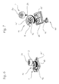
- FIG. 6 shows a perspective view of an alternative embodiment of a measuring device 4 with an associated adjustment element 2.
- the measuring device 4 a transmission gear 4e know, with a rotational movement of the adjusting element 2 can be transmitted to the sensor 4d.
- the transmission gear 4e is so designed such that a translation of the rotational movement of the adjusting member 2 in the ratio of at least 4: 1 to the reference element 4c of the sensor 4d.
- the transmission gear 4e a gear 4e ', which is in engagement with a toothed portion of a shaft 2b of the adjusting element 2.
- the gear 4e ' has a recess 4f, which interrupts the otherwise uniform teeth along the circumference of the gear 4e'.
- the recess has an extension between 5% and 50%, preferably between 20% and 30% of the circumference of the gear 4e '.
- the toothed wheel 4e ' has a resilient element 4g
- the measuring device 4 comprising a holding element 4b for receiving the toothed wheel 4e' and the holding element 4b further comprising a limiting element 4b ', wherein the limiting element 4b' and the elastic element 4g are arranged such that in a position in which the toothed portion of the shaft 2b is rotated into the recess 4f and the gear 4e 'thus leaves an engagement position, the resilient member 4g is pressed against the restricting member 4b', so that the resilient member 4g exerts a restoring force on the gear 4e ', which presses the gear 4e' back into the engaged position.
- the measuring device 4 or the sensor 4d is an angular position sensor.
- the measuring devices are rotary encoders, preferably incremental encoders or absolute encoders.
- the measuring device 4 may also comprise a potentiometer.
- the adjusting element 2 is rotatably mounted on the housing 1 and passes through this, wherein the sealing element 6 is arranged between the housing 1 and the adjusting element 2.
- the invention may be modified in any manner known to those skilled in the art and is therefore not limited to the embodiments shown. Also, individual aspects of the invention or the embodiments can be picked up and combined with each other. Substantial are the ideas underlying the invention, by a person skilled in the knowledge of this description in can be performed in a variety of ways and still be maintained as such.
Landscapes
- Engineering & Computer Science (AREA)
- Mechanical Engineering (AREA)
- General Engineering & Computer Science (AREA)
- Lighting Device Outwards From Vehicle And Optical Signal (AREA)
Abstract
Description
- Die Erfindung betrifft einen Fahrzeugscheinwerfer, insbesondere einen Kraftfahrzeugscheinwerfer, mit einem Gehäuse und einem in dem Gehäuse aufgenommenen Einstellelement sowie einer zur Erfassung der Position und/oder Orientierung des Einstellelements eingerichteten Messvorrichtung, wobei das Einstellelement sowie die Messvorrichtung mit dem Fahrzeugscheinwerfergehäuse verbunden sind.
- Aus dem Stand der Technik bekannte Fahrzeugscheinwerfer weisen häufig manuell bedienbare Stellmittel auf, die mit elektromotorischen Stellmitteln zusammen wirken, um einen optisch relevanten Bauteil in seiner Position und/oder Orientierung zu verändern. Ein solcher Fahrzeugscheinwerfer ist beispielsweise aus dem Patentdokument
AT 513 918 A1 AT 513 918 A1 - Dabei ist es von Nachteil, dass die Verstellmechanik zur Grundeinstellung des optisch relevanten Bauteils kostenintensiv hergestellt und verbaut werden muss und zudem Platz benötigt, wodurch die Abmessungen von solcherart beschaffenen Scheinwerfern nur eingeschränkt frei gewählt werden können.
- Es ist daher eine Aufgabe der Erfindung, einen Fahrzeugscheinwerfer zu schaffen, welcher die genannten Nachteile des Standes der Technik beseitigt und einen robusten, kostengünstigen, kompakten und effizienten Aufbau eines Fahrzeugscheinwerfers ermöglicht, welcher dazu geeignet ist, dass ein darin zumindest teilweise aufgenommenes optisch relevantes Bauteil eingestellt werden kann.
- Diese Aufgabe wird mit einem Fahrzeugscheinwerfer mit einem Gehäuse und einem in dem Gehäuse aufgenommenen Einstellelement sowie einer zur Erfassung der Position und/oder Orientierung des Einstellelements eingerichteten Messvorrichtung der eingangs genannten Art gelöst, indem erfindungsgemäß die Messvorrichtung dazu eingerichtet ist, ein von der Position und/oder Orientierung des Einstellelements abhängiges elektrisches Signal zur Ansteuerung einer Einstellvorrichtung zur Einstellung eines optisch relevanten Bauteils eines Fahrzeugscheinwerfers abzugeben. Bei dem elektrischen Signal kann es um ein Digitalals auch ein Analogsignal handeln. Die Abgabe eines elektrischen Signals durch die Messvorrichtung erlaubt es, dass dieses Signal beispielsweise einem nachgeschalteten elektromotorischen Stellmittel direkt oder indirekt über eine Steuerelektronik zugeführt werden kann, wodurch auf das Vorsehen von rein mechanischen Stellmitteln verzichtet werden kann und damit bereits mit den elektromotorischen Stellmitteln sämtliche gewünschte Einstellfunktionen erfüllt werden können. Eine indirekte Signalleitung bietet dabei den Vorteil, dass das Signal mit Standardelektronik, die nicht an das jeweilige Stellmittel angepasst sein muss, erzeugt werden kann. Außerdem ist die Erfassung der Position und/oder Orientierung des Einstellelements durch eine Messvorrichtung der eingangs genannten Art besonders effizient und kostengünstig und aufgrund der geringen Baugröße gut in einem Gehäuse aufnehmbar.
- Das Gehäuse ist typischerweise ein einziges Bauteil und kann im Prinzip ein beliebiges Gehäuse sein, welches dazu geeignet ist, die entsprechenden Komponenten, sprich das Einstellelement usw., aufzunehmen. Insbesondere kann das Gehäuse ein Kraftfahrzeugscheinwerfergehäuse sein. Das Gehäuse kann aus einem einzigen oder auch aus mehreren Bauteilen und/ oder Abschnitten zusammengesetzt sein.
- Insbesondere kann es vorgesehen sein, dass die Messvorrichtung ein Winkellagegeber ist. Winkellagegeber sind zur Erfassung des Winkels eines Referenzelements zu einer Bezugsachse eingerichtet. In der vorliegenden Erfindung kann das Einstellelement derart mit dem Referenzelement gekoppelt sein, dass das Referenzelement mit Hilfe des Einstellelements gedreht werden kann.
- Bevorzugt handelt es sich bei dem Winkellagegeber um einen Drehgeber, sprich, die Messvorrichtung kann ein Drehgeber sein. Drehgeber verfügen über einen Sensor zur Erfassung einer Drehbewegung/-position und sind üblicherweise dazu eingerichtet, zumindest ein dazu korrespondierendes digitales Ausgangssignal abzugeben.
- Besonders günstig kann es dabei sein, wenn der Drehgeber ein Inkrementalgeber oder ein Absolutwertgeber ist. Bei Inkrementalgebern wird die Orientierung/Position eines Referenzelements inkrementell berechnet, wohingegen Absolutwertgeber dazu eingerichtet sind, die Orientierung/Position des Referenzelements unabhängig von der vorangegangenen Position zu berechnen. Hierfür greifen Absolutwertgeber auf eindeutige Kodiermuster zurück, wobei jeder Orientierung/Position genau ein Muster zugeordnet ist.
- Alternativ dazu kann es vorgesehen sein, dass die Messvorrichtung ein Potentiometergeber ist. Potentiometergeber sind besonders günstig und robust und daher für den Einsatz in Fahrzeugscheinwerfern besonders geeignet.
- Insbesondere kann es vorgesehen sein, dass die Messvorrichtung ein Referenzelement aufweist, das dazu eingerichtet ist, um zumindest 360°, vorzugsweise zumindest 720°, verdreht zu werden. Damit kann eine besonders genaue und fein dosierbare Erfassung der Position und/ oder Orientierung des Einstellelements erfolgen.
- Besonders günstig kann es sein, wenn das Einstellelement drehbar an dem Fahrzeugscheinwerfergehäuse gelagert ist.
- Zudem kann es vorgesehen sein, dass das Einstellelement dazu eingerichtet ist, um zumindest 360°, vorzugsweise zumindest 720°, verdreht zu werden. Damit kann eine besonders hohe Auflösung des durch die Messvorrichtung abgegebenen Signals erzielt werden.
- Um dem Eintritt von unerwünschten Substanzen wie beispielsweise Staub oder Wasser in einen Innenbereich des Gehäuses vorzubeugen, kann bei einer Variante, in der das Einstellelement das Fahrzeugscheinwerfergehäuse durchsetzt, vorgesehen sein, dass zwischen dem Fahrzeugscheinwerfergehäuse und dem Einstellelement ein Dichtungselement, insbesondere ein Dichtungsring, angeordnet ist.
- Zur einfachen Einstellung des Einstellelements kann es insbesondere vorgesehen sein, dass das Einstellelement drehbar an dem Fahrzeugscheinwerfergehäuse gelagert ist und eine koaxial angeordnete Öffnung zur Aufnahme eines Einstellwerkzeuges aufweist. Die koaxiale Anordnung bedeutet dabei, dass die Drehachse des Drehelements durch den Mittelpunkt der Öffnung verläuft.
- Um die Aufnahme eines zur Einstellung eines Fahrzeugscheinwerfers vorgesehenen Sechskantschlüssels zu ermöglichen, kann es vorgesehen sein, dass die Öffnung eine sechseckige Form aufweist.
- Außerdem kann die Öffnung eine schlitz- und/oder eine kreuzförmige Einkerbung in dem Einstellelement ausbilden. Damit können auch Schlitz- oder Kreuzschraubendreher zur Ausrichtung, insbesondere zum Verdrehen des Einstellelements herangezogen werden.
- Insbesondere kann es vorgesehen sein, dass das Einstellelement direkt mit der Messvorrichtung verbunden ist. Unter einer direkten Verbindung wird im Rahmen dieser Offenbarung eine Verbindung verstanden, in der eine Bewegung des Einstellelements ohne Übersetzungsmittel auf die Messvorrichtung, insbesondere ein Referenzelement der Messvorrichtung, übertragen wird.
- Alternativ dazu kann es vorgesehen sein, dass das Einstellelement über ein Übersetzungsgetriebe mit der Messvorrichtung verbunden ist, wobei das Übersetzungsgetriebe dazu eingerichtet ist, eine Drehbewegung des Einstellelements im Verhältnis von zumindest 2:1, 4:1, 8:1,12:1 oder genau 12:1 auf die Messvorrichtung zu übertragen.
- Insbesondere kann es vorgesehen sein, dass das Einstellelement einen verzahnten Abschnitt einer Welle aufweist, welcher mit einem Zahnrad des Übersetzungsgetriebes zur Drehung des Zahnrades im Eingriff steht, wobei das Zahnrad eine Ausnehmung aufweist, die die ansonsten gleichmäßige Verzahnung entlang des Umfangs des Zahnrades unterbricht. Damit kann in einfacher Weise verhindert werden, dass die Messvorrichtung, insbesondere ein Referenzelement der Messvorrichtung, über einen vorgesehen Bereich hinaus gedreht wird. Diese Ausnehmung setzt keine bestimmte Übersetzung des Übersetzungsgetriebes voraus, insbesondere eine Übersetzung ungleich 1:1. Es kann beispielsweise vorgesehen sein, dass das Übersetzungsgetriebe ein beliebiges Übersetzungsverhältnis zwischen beispielsweise 12:1 und 1:12 aufweist.
- Dabei kann es besonders günstig sein, wenn die Ausnehmung eine Erstreckung zwischen 5% und 50%, vorzugsweise zwischen 20% und 30% des Umfangs des Zahnrades aufweist.
- Wird der verzahnte Abschnitt der Welle des Einstellelements soweit gedreht, dass ein weiteres Drehen des Zahnrades durch ein Erreichen der Ausnehmung unterbrochen wird, so kann es unter Umständen vorkommen, dass ein Zurückdrehen des Zahnrades mittels dem Einstellelement aufgrund von fehlendem mechanischem Zusammenspiel nicht möglich ist.
- Zur Vermeidung dieses Problems kann es vorgesehen sein, dass das Zahnrad im Bereich der Ausnehmung ein federndes Element aufweist, wobei die Messvorrichtung ein Halteelement zur Aufnahme des Zahnrades aufweist und das Halteelement ferner ein Begrenzungselement umfasst, wobei das Begrenzungselement und das elastische Element dergestalt angeordnet sind, dass in einer Position, in der der verzahnte Abschnitt der Welle in die Ausnehmung gedreht wird und das Zahnrad somit eine Eingriffsposition verlässt, das federnde Element gegen das Begrenzungselement gedrückt wird, sodass das federnde Element eine rückstellende Kraft auf das Zahnrad ausübt, die das Zahnrad zurück in die Eingriffsposition drückt.
- Das federnde Element sowie das Halteelement bestehen dabei vorzugsweise aus Kunststoff, das Zahnrad und die Welle bzw. der verzahnte Abschnitt der Welle vorzugsweise aus Metall. Diese Materialpaarung ist besonders vorteilhaft.
- Bevorzugt ist das Gehäuse ein Fahrzeugscheinwerfergehäuse. Damit kann das Einstellelement besonders einfach in einem Fahrzeugscheinwerfer aufgenommen werden.
- Alternativ dazu kann das Gehäuse auch ein von dem Fahrzeugscheinwerfer gesondertes, d.h. getrennt angeordnetes, Gehäuse sein. Ein solches gesondertes Gehäuse kann eigenständig gestaltet werden und außerhalb oder innerhalb des Fahrzeugscheinwerfergehäuses oder das Fahrzeugscheinwerfergehäuse durchsetzend angeordnet sein.
- Die Erfindung ist im Folgenden an Hand mehrerer beispielhafter und nicht einschränkender Ausführungsformen näher erläutert, die in den Figuren veranschaulicht sind. Darin zeigt
-
Figur 1 eine Darstellung eines Fahrzeugscheinwerfergehäuse mit zwei darin aufgenommenen Einstellelementen von oben, -
Figur 2 eine Schnittdarstellung des Fahrzeugscheinwerfergehäuses mit darin verbauten Komponenten in einer Seitenansicht, -
Figur 3 eine perspektivische Darstellung einer Messvorrichtung mit dem Einstellelement, -
Figur 4 eine Explosionsdarstellung der Messvorrichtung gemäß derFigur 3 , -
Figur 5 eine Draufsicht auf die Messvorrichtung mit dem Einstellelement gemäß denFiguren 3 und 4 , -
Figur 6 eine perspektivische Darstellung einer alternativen Ausführungsform einer Messvorrichtung mit einem daran gekoppelten Einstellelement, und -
Figur 7 eine perspektivische Explosionsdarstellung der Messvorrichtung gemäßFigur 6 . -
Figur 1 zeigt ein Gehäuse 1, welches als Fahrzeugscheinwerfergehäuse 1 ausgebildet ist, wobei in dem Fahrzeugscheinwerfergehäuse 1 zwei Einstellelemente 2 aufgenommen sind. Des Weiteren ist ein optisch relevanter Bauteil 3 erkennbar, der zumindest teilweise in dem Fahrzeugscheinwerfergehäuse 1 aufgenommen ist. Als optisch relevante Bauteile 3 werden insbesondere Blenden(anordnungen), Lichtquellen, insbesondere LED und/oder Laserlichtquellen, Reflektoren, Linsen und/oder ganze Lichtmodule bzw. Baugruppen, etc. angesehen. Es können daher einzelne oder eine Mehrzahl dieser genannten Komponenten den optisch relevanten Bauteil 3 ausbilden. - Außerdem ist das Fahrzeugscheinwerfergehäuse 1 mit einer Messvorrichtung 4 verbunden, die in den nachfolgenden Figuren dargestellt und später näher diskutiert wird. Die Messvorrichtung 4 ist dazu eingerichtet, die Position und/oder Orientierung des Einstellelements 2 zu überwachen bzw. zu erfassen, wobei ein von der Position und/oder Orientierung des Einstellelements 2 abhängiges elektrisches Signal zur Ansteuerung einer Einstellvorrichtung 5 zur Einstellung eines optisch relevanten Bauteils 3 eines Fahrzeugscheinwerfers abgegeben wird. Eine solche Verstelleinrichtung 5 ist abschnittsweise in
Figur 1 dargestellt und auch in der nachfolgend diskutiertenFigur 2 gezeigt. -
Figur 2 zeigt eine Schnittdarstellung des Fahrzeugscheinwerfergehäuses 1 mit einem darin aufgenommenen Einstellelement 2 sowie der Messvorrichtung 4 als auch der Einstellvorrichtung 5. -
Figur 3 zeigt das Einstellelement 2 sowie die damit verbundenen Messvorrichtung 4 im zusammengebauten Zustand. -
Figur 4 zeigt die Messvorrichtung 4 sowie das Einstellelement 2 derFigur 3 in einer Explosionsdarstellung. Darin ist erkennbar, dass ein Dichtungselement 6 in Form eines Dichtungsringes zwischen dem Einstellelements 2 und der Messvorrichtung 4 angeordnet ist, wobei die Messvorrichtung 4 ein zu dem Einstellelement 2 korrespondierendes Aufnahmerad 4a aufweist, das in eine entsprechende Öffnung eines Halteelements 4b eingesetzt werden kann, um auf das Referenzelement 4c eines Sensors 4d einzugreifen. Nach Einbau der Messvorrichtung 4 und des Einstellelements 2 in das Fahrzeugscheinwerfergehäuse 1 befindet sich das Aufnahmerad 4a auf einer Innenseite des Gehäuses 1, wobei das Einstellelement 2 das Gehäuse 1 durchsetzt. -
Figur 5 zeigt eine Draufsicht auf die Messvorrichtung 4 sowie das Einstellelement 2 gemäß denFiguren 3 bis 4 . Darin ist erkennbar, dass das Einstellelement 2 eine koaxial zur Drehachse des Einstellelements 2 angeordnete Öffnung 2a aufweist, die zur Aufnahme eines Einstellwerkzeuges eingerichtet ist. Die Öffnung 2a weißt im vorliegenden Beispiel eine sechseckige Form auf und verfügt zudem über schlitz- und kreuzförmige Vertiefungen, wodurch Einkerbungen in dem Einstellelement 2 ausgebildet werden. Das Einstellelement 2 ist dabei direkt mit der Messvorrichtung 4, insbesondere dem Referenzelement 4c des Sensors 4d verbunden. -
Figur 6 zeigt eine perspektivische Darstellung einer alternativen Ausführungsform einer Messvorrichtung 4 mit einem damit verbundenen Einstellelement 2. Darin weißt die Messvorrichtung 4 ein Übersetzungsgetriebe 4e auf, mit der eine Drehbewegung des Einstellelements 2 auf den Sensor 4d übertragen werden kann. Das Übersetzungsgetriebe 4e ist so ausgelegt, dass eine Übersetzung der Drehbewegung des Einstellelements 2 im Verhältnis von zumindest 4:1 auf das Referenzelements 4c des Sensors 4d. - Hierfür weißt das Übersetzungsgetriebe 4e ein Zahnrad 4e' auf, welches mit einem verzahnten Abschnitt einer Welle 2b des Einstellelements 2 in Eingriff steht.
- Das Zahnrad 4e' weist eine Ausnehmung 4f auf, die die ansonsten gleichmäßig Verzahnung entlang des Umfangs des Zahnrades 4e' unterbricht. Die Ausnehmung weist eine Erstreckung zwischen 5% und 50%, vorzugsweise zwischen 20% und 30% des Umfangs des Zahnrades 4e' auf.
- Im Bereich der Ausnehmung 4f weist das Zahnrad 4e' ein federndes Element 4g auf, wobei die Messvorrichtung 4 ein Halteelement 4b zur Aufnahme des Zahnrades 4e'und das Halteelement 4b ferner ein Begrenzungselement 4b' umfasst, wobei das Begrenzungselement 4b' und das elastische Element 4g dergestalt angeordnet sind, dass in einer Position, in der der verzahnte Abschnitt der Welle 2b in die Ausnehmung 4f gedreht wird und das Zahnrad 4e' somit eine Eingriffsposition verlässt, das federnde Element 4g gegen das Begrenzungselement 4b' gedrückt wird, sodass das federnde Element 4g eine rückstellende Kraft auf das Zahnrad 4e' ausübt, die das Zahnrad 4e' zurück in die Eingriffsposition drückt.
- Sofern nicht anders angegeben, wurden in den Figuren gleiche Vorrichtungsmerkmal mit den gleichen Bezugszeichen vergeben. In allen gezeigten Beispielen ist die Messvorrichtung 4 bzw. der Sensor 4d ein Winkellagegeber. Insbesondere sind die Messvorrichtungen Drehgeber, vorzugsweise Inkrementalgeber oder Absolutwertgeber. Alternativ dazu kann die Messvorrichtung 4 auch einen Potentiometergeber umfassen. Das Einstellelements 2 ist drehbar an dem Gehäuse 1 gelagert und durchsetzt dieses, wobei das Dichtungselement 6 zwischen dem Gehäuse 1 und dem Einstellelement 2 angeordnet ist.
- In Anbetracht dieser Lehre kann die Erfindung in beliebiger dem Fachmann bekannter Weise abgeändert werden und ist daher nicht auf die gezeigten Ausführungsformen beschränkt. Auch können einzelne Aspekte der Erfindung bzw. der Ausführungsformen aufgegriffen und miteinander kombiniert werden. Wesentlich sind die der Erfindung zugrunde liegenden Gedanken, die durch einen Fachmann in Kenntnis dieser Beschreibung in mannigfaltiger Weise ausgeführt werden können und trotzdem als solche aufrechterhalten bleiben.
Claims (15)
- Fahrzeugscheinwerfer, insbesondere Kraftfahrzeugscheinwerfer, mit einem Gehäuse (1) mit einem in dem Gehäuse (1) aufgenommenen Einstellelement (2) sowie einer zur Erfassung der Position und/oder Orientierung des Einstellelements (2) eingerichteten Messvorrichtung (4), wobei das Einstellelement (2) sowie die Messvorrichtung (4) mit dem Gehäuse (1) verbunden sind,
dadurch gekennzeichnet, dass
die Messvorrichtung (4) dazu eingerichtet ist, ein von der Position und/oder Orientierung des Einstellelements (2) abhängiges elektrisches Signal zur Ansteuerung einer Einstellvorrichtung zur Einstellung eines optisch relevanten Bauteils (3) eines Fahrzeugscheinwerfers abzugeben. - Fahrzeugscheinwerfer nach Anspruch 1, dadurch gekennzeichnet, dass die Messvorrichtung (4) einen Winkellagegeber, einen Potentiometergeber oder einen Drehgeber, insbesondere einen Inkrementalgeber oder einen Absolutwertgeber umfasst.
- Fahrzeugscheinwerfer nach einem der Anspruch 2, dadurch gekennzeichnet, dass die Messvorrichtung (4) ein Referenzelement (4c) aufweist, das dazu eingerichtet ist, um zumindest 360°, vorzugsweise zumindest 720°, verdreht zu werden.
- Fahrzeugscheinwerfer nach einem der Ansprüche 1 bis 3, dadurch gekennzeichnet, dass das Einstellelement (2) drehbar an dem Gehäuse (1) gelagert ist, wobei vorzugsweise das Einstellelement (2) dazu eingerichtet ist, um zumindest 360°, vorzugsweise zumindest 720°, verdreht zu werden.
- Fahrzeugscheinwerfer nach einem der Ansprüche 1 bis 4, dadurch gekennzeichnet, dass das Einstellelement (2) das Gehäuse (1) durchsetzt, wobei zwischen dem Gehäuse (1) und dem Einstellelement (2) ein Dichtungselement (6), insbesondere ein Dichtungsring, angeordnet ist.
- Fahrzeugscheinwerfer nach einem der Ansprüche 1 bis 5, dadurch gekennzeichnet, dass das Einstellelement (2) drehbar an dem Gehäuse (1) gelagert ist und eine koaxial angeordnete Öffnung (2a) zur Aufnahme eines Einstellwerkzeuges aufweist, wobei vorzugsweise die Öffnung (2a) eine sechseckige Form aufweist.
- Fahrzeugscheinwerfer nach Anspruch 6, dadurch gekennzeichnet, dass die Öffnung (2a) eine schlitz- und/ oder eine kreuzförmige Einkerbung in dem Einstellelement (2) ausbildet.
- Fahrzeugscheinwerfer nach einem der Ansprüche 1 bis 7, dadurch gekennzeichnet, dass das Einstellelement (2) direkt mit der Messvorrichtung (4) verbunden ist.
- Fahrzeugscheinwerfer nach einem der Ansprüche 1 bis 7, dadurch gekennzeichnet, dass das Einstellelement (2) über ein Übersetzungsgetriebe (4e) mit der Messvorrichtung (4) verbunden ist, wobei das Übersetzungsgetriebe (4e) dazu eingerichtet ist, eine Drehbewegung des Einstellelements (2) im Verhältnis von zumindest 2:1, 4:1, 8:1, 12:1 oder genau 12:1 auf die Messvorrichtung (4) zu übertragen.
- Fahrzeugscheinwerfer nach Anspruch 9, dadurch gekennzeichnet, dass das Einstellelement (2) einen verzahnten Abschnitt einer Welle (2b) aufweist, welcher mit einem Zahnrad (4e') des Übersetzungsgetriebes (4e) zur Drehung des Zahnrades (4e') im Eingriff steht, wobei das Zahnrad (4e') eine Ausnehmung (4f) aufweist, die die ansonsten gleichmäßige Verzahnung entlang des Umfangs des Zahnrades (4e') unterbricht.
- Fahrzeugscheinwerfer nach Anspruch 10, dadurch gekennzeichnet, dass die Ausnehmung eine Erstreckung zwischen 5% und 50%, vorzugsweise zwischen 20% und 30% des Umfangs des Zahnrades (4e') aufweist.
- Fahrzeugscheinwerfer nach Anspruch 10 oder 11, dadurch gekennzeichnet, dass das Zahnrad (4e') im Bereich der Ausnehmung (4f) ein federndes Element (4g) aufweist, wobei die Messvorrichtung (4) ein Halteelement (4b) zur Aufnahme des Zahnrades (4e') aufweist und das Halteelement (4b) ferner ein Begrenzungselement (4b') umfasst, wobei das Begrenzungselement (4b') und das elastische Element (4g) dergestalt angeordnet sind, dass in einer Position, in der der verzahnte Abschnitt der Welle (2b) in die Ausnehmung (4f) gedreht wird und das Zahnrad (4e') somit eine Eingriffsposition verlässt, das federnde Element (4g) gegen das Begrenzungselement (4b') gedrückt wird, sodass das federnde Element (4g) eine rückstellende Kraft auf das Zahnrad (4e') ausübt, die das Zahnrad (4e') zurück in die Eingriffsposition drückt.
- Fahrzeugscheinwerfer nach Anspruch 12, dadurch gekennzeichnet, dass das federnde Element (4g) und das Halteelement (4b) aus Kunststoff bestehen und das Zahnrad (4e') aus Metall besteht.
- Fahrzeugscheinwerfer nach einem der vorhergehenden Ansprüche, dadurch gekennzeichnet, dass das Gehäuse (1) ein Fahrzeugscheinwerfergehäuse ist.
- Fahrzeugscheinwerfer nach einem der Ansprüche 1 bis 13, dadurch gekennzeichnet, dass das Gehäuse (1) ein von einem Fahrzeugscheinwerfergehäuse gesondertes Gehäuse ist.
Applications Claiming Priority (1)
| Application Number | Priority Date | Filing Date | Title |
|---|---|---|---|
| ATA50213/2015A AT516964B1 (de) | 2015-03-17 | 2015-03-17 | Fahrzeugscheinwerfer, insbesondere Kraftfahrzeugscheinwerfer, mit einem Gehäuse |
Publications (3)
| Publication Number | Publication Date |
|---|---|
| EP3069932A2 true EP3069932A2 (de) | 2016-09-21 |
| EP3069932A3 EP3069932A3 (de) | 2016-11-09 |
| EP3069932B1 EP3069932B1 (de) | 2021-03-24 |
Family
ID=55357916
Family Applications (1)
| Application Number | Title | Priority Date | Filing Date |
|---|---|---|---|
| EP16155618.8A Active EP3069932B1 (de) | 2015-03-17 | 2016-02-15 | Fahrzeugscheinwerfer, insbesondere kraftfahrzeugscheinwerfer, mit einem gehäuse |
Country Status (3)
| Country | Link |
|---|---|
| EP (1) | EP3069932B1 (de) |
| CN (1) | CN105984370B (de) |
| AT (1) | AT516964B1 (de) |
Family Cites Families (9)
| Publication number | Priority date | Publication date | Assignee | Title |
|---|---|---|---|---|
| US3416119A (en) * | 1966-04-20 | 1968-12-10 | Cts Corp | Variable resistance control with clutch mechanism |
| DE1911545A1 (de) * | 1969-03-07 | 1970-09-24 | Prec Electronic Components Ltd | Zahnradantrieb fuer einen Drehwiderstand oder ein Drehpotentiometer |
| DE8115188U1 (de) * | 1980-05-28 | 1981-10-15 | Allen-Bradley Electronics Ltd., Jarrow, Tyne and Wear | "regelbarer widerstand" |
| IT1237749B (it) * | 1989-12-29 | 1993-06-15 | Carello Spa | Proiettore orientabile per veicoli |
| DE19646282A1 (de) * | 1996-11-11 | 1998-05-14 | Bosch Gmbh Robert | Vorrichtung zum Verstellen der Leuchtweite von Scheinwerfern |
| DE202004019043U1 (de) * | 2004-12-09 | 2005-03-31 | Automotive Lighting Reutlingen | Leuchtweitenregulierungsantrieb |
| US7476011B2 (en) * | 2006-02-27 | 2009-01-13 | Sheng-Lung Wu | Lamp assembly with variable illuminating direction |
| CN101900304B (zh) * | 2009-05-27 | 2012-10-24 | 市光工业株式会社 | 车辆用前照灯的调平装置 |
| DE202011003404U1 (de) * | 2011-03-01 | 2011-05-12 | Automotive Lighting Reutlingen Gmbh | Scheinwerfer eines Kraftfahrzeugs |
-
2015
- 2015-03-17 AT ATA50213/2015A patent/AT516964B1/de not_active IP Right Cessation
-
2016
- 2016-02-15 EP EP16155618.8A patent/EP3069932B1/de active Active
- 2016-03-17 CN CN201610151861.9A patent/CN105984370B/zh active Active
Also Published As
| Publication number | Publication date |
|---|---|
| CN105984370A (zh) | 2016-10-05 |
| CN105984370B (zh) | 2018-07-17 |
| AT516964B1 (de) | 2016-12-15 |
| AT516964A1 (de) | 2016-10-15 |
| EP3069932A3 (de) | 2016-11-09 |
| EP3069932B1 (de) | 2021-03-24 |
Similar Documents
| Publication | Publication Date | Title |
|---|---|---|
| DE3610284A1 (de) | Antriebsmechanismus mit einer gewindespindel und spindelmutter | |
| EP1232921A1 (de) | Verriegelungsvorrichtung | |
| DE10161356B4 (de) | Schraubgerät | |
| DE102010032995A1 (de) | Notenriegelung einer motorischen Verschließvorrichtung | |
| DE10015772C1 (de) | Betätigungsvorrichtung zum Verstellen von Einstellpositionen eines Kraftfahrzeugsitzes | |
| EP0212056B1 (de) | Antriebsvorrichtung für Ventile | |
| DE102011056725B4 (de) | Vorrichtung zur Betätigung einer Parksperre eines Fahrzeuggetriebes | |
| DE69000308T2 (de) | Einrichtung zur steuerung der neigung eines scheinwerfers. | |
| EP1722050B1 (de) | Drehriegelschloss | |
| AT516964B1 (de) | Fahrzeugscheinwerfer, insbesondere Kraftfahrzeugscheinwerfer, mit einem Gehäuse | |
| EP2314824B1 (de) | Rohrmotor für eine Verdunkelungsvorrichtung o. dgl. | |
| DE19754271C1 (de) | Signalgeber für einen Stellantrieb | |
| EP1201370B1 (de) | Elektrisch betätigbare Werkstück-Spannvorrichtung | |
| EP0955479A2 (de) | Vorrichtung zum Verbinden von Bauteilen | |
| AT413877B (de) | Stelleinrichtung | |
| DE102007002691A1 (de) | Aktuator zum Verschwenken einer Scheinwerferkomponente | |
| EP1619414A2 (de) | Stelleinrichtung | |
| DE2442622C2 (de) | Motor- und handverstellbares schraubgetriebe | |
| DE2240922A1 (de) | Schraubenschluessel u. dgl. mit einem reversierbaren schaltwerk | |
| DE102010006351B4 (de) | Stellungsanzeige für ein Drehteil | |
| DE19918652A1 (de) | Drehbare Anschlußeinheit für eine elektrische Baueinheit | |
| DE19543421A1 (de) | Drehmomentsensor | |
| DE3528156C2 (de) | Zahnstangengeber mit Selbsthemmung | |
| DE2744232C2 (de) | Handsteuereinrichtung zum Orientieren der Scheinwerfer eines Fahrzeuges | |
| DE10017110A1 (de) | Automatische Getriebeanordnung für ein Getriebe des Zahnradtyps |
Legal Events
| Date | Code | Title | Description |
|---|---|---|---|
| PUAI | Public reference made under article 153(3) epc to a published international application that has entered the european phase |
Free format text: ORIGINAL CODE: 0009012 |
|
| AK | Designated contracting states |
Kind code of ref document: A2 Designated state(s): AL AT BE BG CH CY CZ DE DK EE ES FI FR GB GR HR HU IE IS IT LI LT LU LV MC MK MT NL NO PL PT RO RS SE SI SK SM TR |
|
| AX | Request for extension of the european patent |
Extension state: BA ME |
|
| PUAL | Search report despatched |
Free format text: ORIGINAL CODE: 0009013 |
|
| RAP1 | Party data changed (applicant data changed or rights of an application transferred) |
Owner name: ZKW GROUP GMBH |
|
| AK | Designated contracting states |
Kind code of ref document: A3 Designated state(s): AL AT BE BG CH CY CZ DE DK EE ES FI FR GB GR HR HU IE IS IT LI LT LU LV MC MK MT NL NO PL PT RO RS SE SI SK SM TR |
|
| AX | Request for extension of the european patent |
Extension state: BA ME |
|
| RIC1 | Information provided on ipc code assigned before grant |
Ipc: B60Q 1/076 20060101AFI20161004BHEP Ipc: B60Q 1/00 20060101ALI20161004BHEP |
|
| STAA | Information on the status of an ep patent application or granted ep patent |
Free format text: STATUS: REQUEST FOR EXAMINATION WAS MADE |
|
| 17P | Request for examination filed |
Effective date: 20170509 |
|
| RBV | Designated contracting states (corrected) |
Designated state(s): AL AT BE BG CH CY CZ DE DK EE ES FI FR GB GR HR HU IE IS IT LI LT LU LV MC MK MT NL NO PL PT RO RS SE SI SK SM TR |
|
| STAA | Information on the status of an ep patent application or granted ep patent |
Free format text: STATUS: EXAMINATION IS IN PROGRESS |
|
| 17Q | First examination report despatched |
Effective date: 20200504 |
|
| GRAP | Despatch of communication of intention to grant a patent |
Free format text: ORIGINAL CODE: EPIDOSNIGR1 |
|
| STAA | Information on the status of an ep patent application or granted ep patent |
Free format text: STATUS: GRANT OF PATENT IS INTENDED |
|
| INTG | Intention to grant announced |
Effective date: 20200930 |
|
| GRAS | Grant fee paid |
Free format text: ORIGINAL CODE: EPIDOSNIGR3 |
|
| GRAA | (expected) grant |
Free format text: ORIGINAL CODE: 0009210 |
|
| STAA | Information on the status of an ep patent application or granted ep patent |
Free format text: STATUS: THE PATENT HAS BEEN GRANTED |
|
| AK | Designated contracting states |
Kind code of ref document: B1 Designated state(s): AL AT BE BG CH CY CZ DE DK EE ES FI FR GB GR HR HU IE IS IT LI LT LU LV MC MK MT NL NO PL PT RO RS SE SI SK SM TR |
|
| REG | Reference to a national code |
Ref country code: GB Ref legal event code: FG4D Free format text: NOT ENGLISH |
|
| REG | Reference to a national code |
Ref country code: CH Ref legal event code: EP |
|
| REG | Reference to a national code |
Ref country code: IE Ref legal event code: FG4D Free format text: LANGUAGE OF EP DOCUMENT: GERMAN |
|
| REG | Reference to a national code |
Ref country code: AT Ref legal event code: REF Ref document number: 1374167 Country of ref document: AT Kind code of ref document: T Effective date: 20210415 Ref country code: DE Ref legal event code: R096 Ref document number: 502016012640 Country of ref document: DE |
|
| REG | Reference to a national code |
Ref country code: LT Ref legal event code: MG9D |
|
| PG25 | Lapsed in a contracting state [announced via postgrant information from national office to epo] |
Ref country code: NO Free format text: LAPSE BECAUSE OF FAILURE TO SUBMIT A TRANSLATION OF THE DESCRIPTION OR TO PAY THE FEE WITHIN THE PRESCRIBED TIME-LIMIT Effective date: 20210624 Ref country code: BG Free format text: LAPSE BECAUSE OF FAILURE TO SUBMIT A TRANSLATION OF THE DESCRIPTION OR TO PAY THE FEE WITHIN THE PRESCRIBED TIME-LIMIT Effective date: 20210624 Ref country code: GR Free format text: LAPSE BECAUSE OF FAILURE TO SUBMIT A TRANSLATION OF THE DESCRIPTION OR TO PAY THE FEE WITHIN THE PRESCRIBED TIME-LIMIT Effective date: 20210625 Ref country code: FI Free format text: LAPSE BECAUSE OF FAILURE TO SUBMIT A TRANSLATION OF THE DESCRIPTION OR TO PAY THE FEE WITHIN THE PRESCRIBED TIME-LIMIT Effective date: 20210324 Ref country code: HR Free format text: LAPSE BECAUSE OF FAILURE TO SUBMIT A TRANSLATION OF THE DESCRIPTION OR TO PAY THE FEE WITHIN THE PRESCRIBED TIME-LIMIT Effective date: 20210324 |
|
| PG25 | Lapsed in a contracting state [announced via postgrant information from national office to epo] |
Ref country code: SE Free format text: LAPSE BECAUSE OF FAILURE TO SUBMIT A TRANSLATION OF THE DESCRIPTION OR TO PAY THE FEE WITHIN THE PRESCRIBED TIME-LIMIT Effective date: 20210324 Ref country code: RS Free format text: LAPSE BECAUSE OF FAILURE TO SUBMIT A TRANSLATION OF THE DESCRIPTION OR TO PAY THE FEE WITHIN THE PRESCRIBED TIME-LIMIT Effective date: 20210324 Ref country code: LV Free format text: LAPSE BECAUSE OF FAILURE TO SUBMIT A TRANSLATION OF THE DESCRIPTION OR TO PAY THE FEE WITHIN THE PRESCRIBED TIME-LIMIT Effective date: 20210324 |
|
| REG | Reference to a national code |
Ref country code: NL Ref legal event code: MP Effective date: 20210324 |
|
| PG25 | Lapsed in a contracting state [announced via postgrant information from national office to epo] |
Ref country code: NL Free format text: LAPSE BECAUSE OF FAILURE TO SUBMIT A TRANSLATION OF THE DESCRIPTION OR TO PAY THE FEE WITHIN THE PRESCRIBED TIME-LIMIT Effective date: 20210324 |
|
| PG25 | Lapsed in a contracting state [announced via postgrant information from national office to epo] |
Ref country code: SM Free format text: LAPSE BECAUSE OF FAILURE TO SUBMIT A TRANSLATION OF THE DESCRIPTION OR TO PAY THE FEE WITHIN THE PRESCRIBED TIME-LIMIT Effective date: 20210324 Ref country code: CZ Free format text: LAPSE BECAUSE OF FAILURE TO SUBMIT A TRANSLATION OF THE DESCRIPTION OR TO PAY THE FEE WITHIN THE PRESCRIBED TIME-LIMIT Effective date: 20210324 Ref country code: EE Free format text: LAPSE BECAUSE OF FAILURE TO SUBMIT A TRANSLATION OF THE DESCRIPTION OR TO PAY THE FEE WITHIN THE PRESCRIBED TIME-LIMIT Effective date: 20210324 Ref country code: LT Free format text: LAPSE BECAUSE OF FAILURE TO SUBMIT A TRANSLATION OF THE DESCRIPTION OR TO PAY THE FEE WITHIN THE PRESCRIBED TIME-LIMIT Effective date: 20210324 |
|
| PG25 | Lapsed in a contracting state [announced via postgrant information from national office to epo] |
Ref country code: PT Free format text: LAPSE BECAUSE OF FAILURE TO SUBMIT A TRANSLATION OF THE DESCRIPTION OR TO PAY THE FEE WITHIN THE PRESCRIBED TIME-LIMIT Effective date: 20210726 Ref country code: PL Free format text: LAPSE BECAUSE OF FAILURE TO SUBMIT A TRANSLATION OF THE DESCRIPTION OR TO PAY THE FEE WITHIN THE PRESCRIBED TIME-LIMIT Effective date: 20210324 Ref country code: ES Free format text: LAPSE BECAUSE OF FAILURE TO SUBMIT A TRANSLATION OF THE DESCRIPTION OR TO PAY THE FEE WITHIN THE PRESCRIBED TIME-LIMIT Effective date: 20210324 Ref country code: SK Free format text: LAPSE BECAUSE OF FAILURE TO SUBMIT A TRANSLATION OF THE DESCRIPTION OR TO PAY THE FEE WITHIN THE PRESCRIBED TIME-LIMIT Effective date: 20210324 Ref country code: RO Free format text: LAPSE BECAUSE OF FAILURE TO SUBMIT A TRANSLATION OF THE DESCRIPTION OR TO PAY THE FEE WITHIN THE PRESCRIBED TIME-LIMIT Effective date: 20210324 Ref country code: IS Free format text: LAPSE BECAUSE OF FAILURE TO SUBMIT A TRANSLATION OF THE DESCRIPTION OR TO PAY THE FEE WITHIN THE PRESCRIBED TIME-LIMIT Effective date: 20210724 |
|
| REG | Reference to a national code |
Ref country code: DE Ref legal event code: R097 Ref document number: 502016012640 Country of ref document: DE |
|
| PG25 | Lapsed in a contracting state [announced via postgrant information from national office to epo] |
Ref country code: AL Free format text: LAPSE BECAUSE OF FAILURE TO SUBMIT A TRANSLATION OF THE DESCRIPTION OR TO PAY THE FEE WITHIN THE PRESCRIBED TIME-LIMIT Effective date: 20210324 Ref country code: DK Free format text: LAPSE BECAUSE OF FAILURE TO SUBMIT A TRANSLATION OF THE DESCRIPTION OR TO PAY THE FEE WITHIN THE PRESCRIBED TIME-LIMIT Effective date: 20210324 |
|
| PLBE | No opposition filed within time limit |
Free format text: ORIGINAL CODE: 0009261 |
|
| STAA | Information on the status of an ep patent application or granted ep patent |
Free format text: STATUS: NO OPPOSITION FILED WITHIN TIME LIMIT |
|
| PG25 | Lapsed in a contracting state [announced via postgrant information from national office to epo] |
Ref country code: SI Free format text: LAPSE BECAUSE OF FAILURE TO SUBMIT A TRANSLATION OF THE DESCRIPTION OR TO PAY THE FEE WITHIN THE PRESCRIBED TIME-LIMIT Effective date: 20210324 |
|
| 26N | No opposition filed |
Effective date: 20220104 |
|
| PG25 | Lapsed in a contracting state [announced via postgrant information from national office to epo] |
Ref country code: IS Free format text: LAPSE BECAUSE OF FAILURE TO SUBMIT A TRANSLATION OF THE DESCRIPTION OR TO PAY THE FEE WITHIN THE PRESCRIBED TIME-LIMIT Effective date: 20210724 |
|
| PG25 | Lapsed in a contracting state [announced via postgrant information from national office to epo] |
Ref country code: MC Free format text: LAPSE BECAUSE OF FAILURE TO SUBMIT A TRANSLATION OF THE DESCRIPTION OR TO PAY THE FEE WITHIN THE PRESCRIBED TIME-LIMIT Effective date: 20210324 |
|
| REG | Reference to a national code |
Ref country code: CH Ref legal event code: PL |
|
| REG | Reference to a national code |
Ref country code: BE Ref legal event code: MM Effective date: 20220228 |
|
| GBPC | Gb: european patent ceased through non-payment of renewal fee |
Effective date: 20220215 |
|
| PG25 | Lapsed in a contracting state [announced via postgrant information from national office to epo] |
Ref country code: LU Free format text: LAPSE BECAUSE OF NON-PAYMENT OF DUE FEES Effective date: 20220215 |
|
| PG25 | Lapsed in a contracting state [announced via postgrant information from national office to epo] |
Ref country code: LI Free format text: LAPSE BECAUSE OF NON-PAYMENT OF DUE FEES Effective date: 20220228 Ref country code: IT Free format text: LAPSE BECAUSE OF FAILURE TO SUBMIT A TRANSLATION OF THE DESCRIPTION OR TO PAY THE FEE WITHIN THE PRESCRIBED TIME-LIMIT Effective date: 20210324 Ref country code: IE Free format text: LAPSE BECAUSE OF NON-PAYMENT OF DUE FEES Effective date: 20220215 Ref country code: GB Free format text: LAPSE BECAUSE OF NON-PAYMENT OF DUE FEES Effective date: 20220215 Ref country code: CH Free format text: LAPSE BECAUSE OF NON-PAYMENT OF DUE FEES Effective date: 20220228 |
|
| PG25 | Lapsed in a contracting state [announced via postgrant information from national office to epo] |
Ref country code: BE Free format text: LAPSE BECAUSE OF NON-PAYMENT OF DUE FEES Effective date: 20220228 |
|
| REG | Reference to a national code |
Ref country code: AT Ref legal event code: MM01 Ref document number: 1374167 Country of ref document: AT Kind code of ref document: T Effective date: 20220215 |
|
| PG25 | Lapsed in a contracting state [announced via postgrant information from national office to epo] |
Ref country code: AT Free format text: LAPSE BECAUSE OF NON-PAYMENT OF DUE FEES Effective date: 20220215 |
|
| P01 | Opt-out of the competence of the unified patent court (upc) registered |
Effective date: 20230528 |
|
| PG25 | Lapsed in a contracting state [announced via postgrant information from national office to epo] |
Ref country code: HU Free format text: LAPSE BECAUSE OF FAILURE TO SUBMIT A TRANSLATION OF THE DESCRIPTION OR TO PAY THE FEE WITHIN THE PRESCRIBED TIME-LIMIT; INVALID AB INITIO Effective date: 20160215 |
|
| PG25 | Lapsed in a contracting state [announced via postgrant information from national office to epo] |
Ref country code: MK Free format text: LAPSE BECAUSE OF FAILURE TO SUBMIT A TRANSLATION OF THE DESCRIPTION OR TO PAY THE FEE WITHIN THE PRESCRIBED TIME-LIMIT Effective date: 20210324 Ref country code: CY Free format text: LAPSE BECAUSE OF FAILURE TO SUBMIT A TRANSLATION OF THE DESCRIPTION OR TO PAY THE FEE WITHIN THE PRESCRIBED TIME-LIMIT Effective date: 20210324 |
|
| PG25 | Lapsed in a contracting state [announced via postgrant information from national office to epo] |
Ref country code: MT Free format text: LAPSE BECAUSE OF FAILURE TO SUBMIT A TRANSLATION OF THE DESCRIPTION OR TO PAY THE FEE WITHIN THE PRESCRIBED TIME-LIMIT Effective date: 20210324 |
|
| PGFP | Annual fee paid to national office [announced via postgrant information from national office to epo] |
Ref country code: FR Payment date: 20250221 Year of fee payment: 10 |
|
| REG | Reference to a national code |
Ref country code: DE Ref legal event code: R084 Ref document number: 502016012640 Country of ref document: DE |
|
| PG25 | Lapsed in a contracting state [announced via postgrant information from national office to epo] |
Ref country code: TR Free format text: LAPSE BECAUSE OF FAILURE TO SUBMIT A TRANSLATION OF THE DESCRIPTION OR TO PAY THE FEE WITHIN THE PRESCRIBED TIME-LIMIT Effective date: 20210324 |
|
| PGFP | Annual fee paid to national office [announced via postgrant information from national office to epo] |
Ref country code: DE Payment date: 20260217 Year of fee payment: 11 |