EP3069836B1 - Überlappungsvorrichtung - Google Patents
Überlappungsvorrichtung Download PDFInfo
- Publication number
- EP3069836B1 EP3069836B1 EP16159140.9A EP16159140A EP3069836B1 EP 3069836 B1 EP3069836 B1 EP 3069836B1 EP 16159140 A EP16159140 A EP 16159140A EP 3069836 B1 EP3069836 B1 EP 3069836B1
- Authority
- EP
- European Patent Office
- Prior art keywords
- tracks
- track
- overlapping
- portions
- deflection
- Prior art date
- Legal status (The legal status is an assumption and is not a legal conclusion. Google has not performed a legal analysis and makes no representation as to the accuracy of the status listed.)
- Active
Links
Images




Classifications
-
- B—PERFORMING OPERATIONS; TRANSPORTING
- B26—HAND CUTTING TOOLS; CUTTING; SEVERING
- B26D—CUTTING; DETAILS COMMON TO MACHINES FOR PERFORATING, PUNCHING, CUTTING-OUT, STAMPING-OUT OR SEVERING
- B26D7/00—Details of apparatus for cutting, cutting-out, stamping-out, punching, perforating, or severing by means other than cutting
- B26D7/27—Means for performing other operations combined with cutting
- B26D7/32—Means for performing other operations combined with cutting for conveying or stacking cut product
-
- B—PERFORMING OPERATIONS; TRANSPORTING
- B65—CONVEYING; PACKING; STORING; HANDLING THIN OR FILAMENTARY MATERIAL
- B65G—TRANSPORT OR STORAGE DEVICES, e.g. CONVEYORS FOR LOADING OR TIPPING, SHOP CONVEYOR SYSTEMS OR PNEUMATIC TUBE CONVEYORS
- B65G15/00—Conveyors having endless load-conveying surfaces, i.e. belts and like continuous members, to which tractive effort is transmitted by means other than endless driving elements of similar configuration
- B65G15/30—Belts or like endless load-carriers
- B65G15/50—Endless load-carriers consisting of a series of parallel ropes or belt strips
-
- B—PERFORMING OPERATIONS; TRANSPORTING
- B65—CONVEYING; PACKING; STORING; HANDLING THIN OR FILAMENTARY MATERIAL
- B65G—TRANSPORT OR STORAGE DEVICES, e.g. CONVEYORS FOR LOADING OR TIPPING, SHOP CONVEYOR SYSTEMS OR PNEUMATIC TUBE CONVEYORS
- B65G41/00—Supporting frames or bases for conveyors as a whole, e.g. transportable conveyor frames
-
- B—PERFORMING OPERATIONS; TRANSPORTING
- B65—CONVEYING; PACKING; STORING; HANDLING THIN OR FILAMENTARY MATERIAL
- B65G—TRANSPORT OR STORAGE DEVICES, e.g. CONVEYORS FOR LOADING OR TIPPING, SHOP CONVEYOR SYSTEMS OR PNEUMATIC TUBE CONVEYORS
- B65G47/00—Article or material-handling devices associated with conveyors; Methods employing such devices
- B65G47/02—Devices for feeding articles or materials to conveyors
- B65G47/04—Devices for feeding articles or materials to conveyors for feeding articles
- B65G47/06—Devices for feeding articles or materials to conveyors for feeding articles from a single group of articles arranged in orderly pattern, e.g. workpieces in magazines
- B65G47/08—Devices for feeding articles or materials to conveyors for feeding articles from a single group of articles arranged in orderly pattern, e.g. workpieces in magazines spacing or grouping the articles during feeding
- B65G47/084—Devices for feeding articles or materials to conveyors for feeding articles from a single group of articles arranged in orderly pattern, e.g. workpieces in magazines spacing or grouping the articles during feeding grouping articles in a predetermined 2-dimensional pattern
-
- B—PERFORMING OPERATIONS; TRANSPORTING
- B65—CONVEYING; PACKING; STORING; HANDLING THIN OR FILAMENTARY MATERIAL
- B65G—TRANSPORT OR STORAGE DEVICES, e.g. CONVEYORS FOR LOADING OR TIPPING, SHOP CONVEYOR SYSTEMS OR PNEUMATIC TUBE CONVEYORS
- B65G47/00—Article or material-handling devices associated with conveyors; Methods employing such devices
- B65G47/52—Devices for transferring articles or materials between conveyors i.e. discharging or feeding devices
- B65G47/68—Devices for transferring articles or materials between conveyors i.e. discharging or feeding devices adapted to receive articles arriving in one layer from one conveyor lane and to transfer them in individual layers to more than one conveyor lane or to one broader conveyor lane, or vice versa, e.g. combining the flows of articles conveyed by more than one conveyor
-
- B—PERFORMING OPERATIONS; TRANSPORTING
- B65—CONVEYING; PACKING; STORING; HANDLING THIN OR FILAMENTARY MATERIAL
- B65G—TRANSPORT OR STORAGE DEVICES, e.g. CONVEYORS FOR LOADING OR TIPPING, SHOP CONVEYOR SYSTEMS OR PNEUMATIC TUBE CONVEYORS
- B65G57/00—Stacking of articles
- B65G57/32—Stacking of articles characterised by stacking during transit
-
- B—PERFORMING OPERATIONS; TRANSPORTING
- B26—HAND CUTTING TOOLS; CUTTING; SEVERING
- B26D—CUTTING; DETAILS COMMON TO MACHINES FOR PERFORATING, PUNCHING, CUTTING-OUT, STAMPING-OUT OR SEVERING
- B26D2210/00—Machines or methods used for cutting special materials
- B26D2210/02—Machines or methods used for cutting special materials for cutting food products, e.g. food slicers
Definitions
- the invention relates to an overlapping unit according to the preamble of claim 1 and a method with the features of claim 11 for the lateral overlapping of portions transported in a longitudinal direction, each of which comprises at least one slice separated from a food product.
- a lateral overlap of portions may be necessary, for example, when several food products lying next to one another, such as sausage or cheese loaves, are cut at the same time using a slicing device, e.g. a high-speed slicer, and as a result an individual portion is produced from one or more food slices in each lane.
- a slicing device e.g. a high-speed slicer
- portions have usually been overlapped laterally using relatively long conveyor systems, the length of which can be, for example, 3 to 4 m.
- Known overlappers comprise two continuously separated belt conveyors arranged one above the other at different levels, to which a so-called rocker is assigned on the input side, by means of which part of the incoming portions is directed to the upper conveyor level and another part of the incoming portions to the lower conveyor level.
- a portion from the upper conveyor level is then deposited on a portion transported in the lower conveyor level.
- Each of the two conveyor levels is equipped with at least one of its own drives so that the conveyor speeds can be adjusted accordingly. A further drive is required for the separate rocker assigned to the input side.
- a device having the features of the preamble of claim 1 is known from EP 0 274 229 A2 known.
- DE 36 42 123 A1 (the content of the EP 0 274 229 A2 corresponds)
- WO 2004/011209 A1 also describe devices for overlapping portions in which several individual conveyors are arranged one behind the other.
- US 6,152 284 A conveyor device with belt conveyors is known which is not designed for overlapping portions.
- the object of the invention is therefore to provide a device and a method of the type mentioned at the outset which enable a lateral overlapping of portions in the simplest and most cost-effective manner possible and, in particular, are as versatile as possible.
- two portions lying next to each other can be brought to different heights without the aid of additional equipment and then placed on top of each other. Since the two tracks are diverted around a common input axis on the inlet side, the inventive Connect the overlap unit directly to a previous conveyor without the need for a rocker.
- the two tracks of the belt conveyor can be guided in such a way that the different height levels are reached within a comparatively short conveying distance in the longitudinal direction.
- the overlap unit according to the invention therefore only requires a comparatively short installation length. It has been shown that less than half the installation length required by known overlappers is sufficient for an overlap unit according to the invention.
- the belt conveyor comprises a plurality of conveyor belts for each of the two tracks, which run next to one another at a distance from one another.
- the conveyor belts are preferably round belts with a circular, oval or elliptical cross-section, although other cross-sectional shapes are also possible and, for example, so-called trapezoidal belts or T-belts can also be used.
- Such conveyor belts and thus the tracks formed by them can be guided and redirected simply and reliably in the desired manner, both by changing the gradient, i.e. in height, and by changing the direction in the transverse direction.
- a particular advantage of the invention is that in order to implement a specific overlap concept, i.e. to generate a specific deposit pattern of the portions conveyed by the two tracks, no components of the overlap unit need to be adjusted during overlap operation.
- the type of overlap, i.e. the deposit pattern only needs to be determined once at the beginning by setting the course of the two tracks.
- both tracks can be driven together.
- a common drive via the common input axis is particularly preferred. Consequently, it is possible to operate the overlap unit according to the invention with only a single drive.
- the invention thus makes it possible to provide overlapping units that require relatively little space, are comparatively simple in design and are very cost-effective, which in turn, according to a preferred embodiment of the invention, creates the advantageous possibility of implementing a cassette or module concept in which the overlapping unit is designed as a module that can be handled as a whole and can, for example, be removed as a whole from a substructure or frame and reinserted.
- a stationary substructure to which the cassette can be coupled can be provided for such an overlapping cassette.
- this basically makes it possible to provide any number of differently configured overlapping units that can be optionally inserted into the respective system by the user in order to implement a desired, application-specific overlapping concept with a correspondingly configured overlapping cassette.
- overlapping units each configured in a particularly coordinated manner, in succession in order to implement overlapping concepts with corresponding overlapping processes that take place successively one after the other.
- one or more overlapping units into a higher-level functional unit, in particular into a high-speed slicer.
- an overlapping unit can be integrated into the so-called portioning system of a food slicer and coupled in particular to the slicer frame.
- the overlapping unit can be used, for example, instead of a so-called control belt, which is arranged downstream of a portioning belt of the slicer, on which the portions are formed from the slices cut off by the slicer's cutting blade.
- the overlapping unit according to the invention thus provides a large range of variation options for a plant operator, so that even smaller batches with different deposition patterns can be processed.
- the inlet-side and/or outlet-side deflection position can be changed in the transverse direction for at least one of the tracks.
- the track spacing between the upper track and the lower track can be adjusted.
- the track spacing and the track positions in the transverse direction can be adapted to an upstream conveyor via which the portions enter.
- the degree of lateral overlap can be adjusted by changing the deflection positions.
- an overlapping unit configured in this way may be required, for example, to enable portions to simply "pass through” without lateral overlap. In this case, portions can be brought together or apart, and their lateral distance can thus be reduced or increased.
- An overlap-free passage of portions does not have to be a straight-ahead journey parallel to the longitudinal direction.
- An overlap-free journey may be desired, for example, within a conveyor section comprising several modules, with which both applications without overlap and applications with overlap should be possible and which comprises a plurality of receiving spaces for interchangeable conveyor modules.
- the overlapping unit according to the invention can therefore also be used as a pure conveyor module with tracks running parallel or diagonally away from each other or towards each other without portion overlap, if the tracks are suitably adjustable.
- the overlap unit according to the invention can therefore be freely configurable with regard to track guidance, either manually or motor-driven via an associated control system, in order to offer a wide variety of applications.
- a common drive can be assigned to both tracks of the overlapping unit.
- the drive can be via the common input axis.
- This drive shaft can be provided with deflection rollers or deflection sleeves for the conveyor elements of the two tracks that can be coupled in a rotationally fixed manner, for example with grooved sleeves for conveyor belts, whereby the shape of the grooves is adapted to the cross-section of the belts.
- the two tracks can also be driven on the outlet side using the two output axes.
- Each output axis can be assigned its own drive so that the conveying speeds of the two tracks can be set independently of each other by controlling the two drives accordingly.
- the conveying speeds of the two tracks can also be independently controlled on the inlet side on the common input axis, for example by providing a so-called "shaft in shaft” concept with two concentric, nested drive shafts, each of which is assigned its own drive.
- a so-called "shaft in shaft” concept with two concentric, nested drive shafts, each of which is assigned its own drive.
- the overlapping unit has a plurality of track pairs, each with an upper track and a lower track, which are arranged alternately in the transverse direction. If only a single track pair with a single upper track and a single lower track, the common input axle can be split and provided with a left-hand drive for one track and a right-hand drive for the other track.
- the invention is not limited to the creation of a lateral overlap of the portions. It is also possible to create a longitudinal offset between the two portions by appropriately setting the conveying speeds of the two tracks. A comparatively simple possibility for appropriately regulating the conveying speeds, which requires two drives, is obtained if each of the two tracks has its own drive. If, on the other hand, a common drive is provided, for example on the common input axis, the conveying speeds of the two tracks can be adjusted relative to one another by ensuring different conveying lengths in the two tracks. This can be done, for example, by the two tracks differing from one another in terms of the deflection path on the input axis and/or on the output axes. Differently long deflection paths can be achieved, for example, by deflection rollers or deflection sleeves with different diameters.
- a longitudinal offset of the portions conveyed in the tracks can be adjusted to a predetermined amount by adjusting the conveying speeds of the tracks relative to one another.
- this conveyor length difference can be compensated by setting the conveyor speeds of the two tracks differently. If only one common drive is provided, for example on the common input axis, such compensation can be achieved by using different long deflection paths can be achieved, for example, on the input axis or on the output axes.
- the conveying speed of this conveyor lies between the conveying speeds of the two tracks.
- the guidance of the two tracks determines the degree of lateral overlap of the portions conveyed by the tracks as well as the transverse position of the total portion formed by the portions lying on top of each other on the outlet side. Only one track can contribute to the transverse offset of the portions relative to each other required for lateral overlap, although it is also possible for both tracks to contribute.
- both the upper track and the lower track run obliquely to the longitudinal direction. Both tracks run obliquely towards each other.
- a particularly advantageous guidance of the two tracks which in particular enables a short installation length and at the same time ensures an undisturbed portion transport, can be realized between the input axis and the output axes by a correspondingly clever deflection of the tracks.
- an intermediate deflection is provided for the upper track between the input axis and the output axis, which preferably has two deflection axes that are spaced apart longitudinally as well as those located at different heights.
- An intermediate deflection can be used to ensure that the two tracks have a sufficiently large height difference on the outlet side so that portions conveyed on the lower track are not affected by the lower or returning run of the upper track.
- the intermediate deflection can be effective in changing the gradient in such a way that the upper track runs in an output-side region with both strands above the lower track.
- the intermediate deflection can ensure that the upper track and in particular its returning lower run quickly gains height in order to avoid any impairment of the portions on the lower track in an entry-side area.
- An intermediate deflection can also be carried out in the transverse direction in particular in order to prevent or reduce a lateral overlap of the two tracks at least as long as it takes, i.e. to keep the two tracks laterally apart until a sufficiently large clear height is reached between the tracks for portions conveyed by means of the lower track.
- the intermediate deflection can be effective in changing the direction in such a way that the lower run of the upper track in an input-side region encloses a different angle with the longitudinal direction than the upper run of the upper track.
- the intermediate deflection can avoid or reduce a lateral overlap between the lower run of the upper track and the upper run of the lower track until a predetermined clear height between these two runs is reached. This prevents the two strands from touching each other and/or a portion resting on the upper strand of the lower track coming into contact with the lower strand of the upper track.
- an intermediate deflection for the lower run of the upper track is effective both in changing the gradient and in changing the direction, in particular the lower run of the upper track is pulled both upwards and to the side.
- the intermediate deflection can, for example, comprise one or more deflection axes running parallel to the input axis and to the output axes, on which, for example, deflection rollers or deflection sleeves are arranged so as to be freely rotatable, the transverse positions of which can be set or adjusted in accordance with the desired track guidance.
- the position of one or each deflection axis relative to the input axis and/or at least one of the output axes can be adjustable in order to be able to adapt the overlapping unit to a particular application and in particular to the height of the portions to be conveyed.
- an intermediate deflection is provided exclusively for the upper track.
- the two strands of the lower track can each run in a straight line between the input axis and the output axis.
- the overlapping unit can comprise either exactly one pair of tracks or several pairs of tracks arranged next to one another in the transverse direction, each with an upper track and a lower track. In this way, a large variety of overlapping concepts and storage patterns for entire portions can be implemented. All pairs of tracks can be assigned a common drive, e.g. in the form of a common drive shaft forming the input axis.
- the overlap unit can be designed as a cassette, namely as a module which is coupled to a stationary substructure during operation and can be removed and reinserted as a whole, which comprises a base for coupling to the substructure and the belt conveyor carried by the base.
- One or more drive motors for the cassette can be integrated into the substructure and remain on the substructure when the cassette is removed. With such a concept, only the component that needs to be configured differently to implement specific applications can be replaced in a simple and cost-effective manner.
- An overlapping device comprises several overlapping units which are connected one behind the other in the longitudinal direction.
- the overlapping device according to the invention which comprises several overlapping units of the type disclosed here, can be part of a system, also referred to as a production line, which is arranged downstream of at least one slicing device for food products.
- the overlapping device according to the invention can also be a complete production line including one or more high-speed slicers and a downstream system.
- overlapping units can be arranged directly one after the other and in a way that corresponds to one another, ie coordinated with one another, although this is not mandatory.
- Pure drive-through sections or drive-through modules without overlapping functions can be provided between overlapping units according to the invention.
- an overlap unit can be configured or configurable in such a way that no overlap occurs and the two tracks run continuously next to each other or lead towards or away from each other, i.e. such an overlap unit according to the invention can, if required, also be used as a pure drive-through module or as a merging or separating module.
- consecutive overlapping units according to the invention can be configured differently in such a way that, viewed in the longitudinal direction, the desired final total portion is formed successively by overlapping processes which take place one after the other on each of the overlapping units.
- the invention also relates to an overlap unit per se, which does not comprise any additional upstream or downstream devices.
- the overlapping unit can be designed as a cassette, namely as a module coupled to a stationary substructure during operation, which can be removed and reinserted as a whole and which comprises a base for coupling to the substructure and the belt conveyor carried by the base.
- the substructure can be a slicer frame, so that an overlapping unit according to the invention can be integrated into a slicer.
- the invention further relates to a method for forming total portions with the features of claim 11.
- the total portions can be formed successively by means of several overlapping units arranged one after the other in the longitudinal direction by overlapping processes that take place one after the other at each of the overlapping units.
- the method can provide that a longitudinal offset of the portions conveyed in the tracks is set to a predetermined value by adjusting the conveying speeds of the tracks relative to each other.
- a conveying length difference between the two tracks is compensated by setting the conveying speeds of the two tracks differently.
- the individual portions that are conveyed by means of the at least two tracks of the belt conveyor of the overlapping unit according to the invention can be the same, although this is not mandatory.
- the portions can also have been produced from different types of product, so that the total portions formed on the outlet side are then each so-called mixed portions.
- the portions each comprise several product slices arranged in a shingled manner in the longitudinal direction.
- stacked portions can also be overlapped laterally.
- the portions can also each comprise only a single slice.
- a total portion formed by means of the overlapping unit according to the invention then comprises, for example, two individual slices overlapping one another laterally.
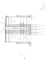
- the illustrated overlapping unit 15 is designed as a cassette which is connected to a substructure (not shown), for example a frame a slicer or a frame forming part of a conveyor line.
- a substructure for example a frame a slicer or a frame forming part of a conveyor line.
- the overlapping unit 15 is provided with a frame-like base 16.
- the overlapping cassette 15 shown can therefore be handled as a whole and thus forms a module that can be removed as a whole from a respective substructure or frame and reinserted.
- the base frame 16 carries a belt conveyor which, in the embodiment shown, comprises two pairs of tracks, each comprising an upper track 17 and a lower track 19, which are arranged alternately next to one another in the transverse direction.
- This belt conveyor defines a longitudinal direction T between an input shaft 21 on the inlet side, designed as a common drive shaft for all tracks 17, 19, and two passive rod-shaped output shafts 27, 29.
- Each track 17, 19 comprises several conveyor belts which are deflected on the inlet side around the common input axis 21 and on the output side around the output axes 27, 29 which are located at different height levels and approximately vertically one above the other.
- the guidance of the upper tracks 17 is additionally determined by two passive rod-shaped deflection axes 23, 25, which form an intermediate deflection for the respective upper track 17, which will be discussed in more detail below.
- the two deflection axes 23, 25 are attached to a common swing arm 43, which can be pivoted about the common input axis 21.
- the position of the intermediate deflection for the upper tracks 17 formed by the two deflection axes 23, 25 can thereby be changed relative to the base 16 and thus relative to the input axis 21 and to the output axes 27, 29, which are mounted on the base 16.
- Each pair of tracks 17, 19 serves to transport two incoming portions 11, which here each comprise several slices 13 arranged in a shingle pattern in the longitudinal direction T and separated from a food product by means of a slicer, in the longitudinal direction T and to place them on top of one another with a predetermined transverse offset, i.e. a predetermined lateral overlap.
- a left portion 11 is conveyed by means of the lower track 17 and a right portion 11 by means of the upper track 17, so that at the outlet end of the overlap unit 15 both portions 11 are at different heights.
- the left portion 11 is conveyed by means of the upper, incoming run of the lower track 19 and the right portion 11 is conveyed by means of the upper, incoming run of the upper track 17.
- Grooved deflection sleeves are used for the deflection of the conveyor belts forming tracks 17, 19, which are referred to below in connection with the Fig. 5 to 8 will be discussed in more detail and which are arranged on the respective axis.
- the deflection sleeves on the two output axes 27, 29 and the two intermediate deflection axes 23, 25 are freely rotatable, whereas the inlet-side deflection sleeves are coupled in a rotationally fixed manner to the drive shaft 21 forming the input axis.
- the drive shaft 21 is connected to a drive motor (not shown), for example via a belt or gear drive, whereby the drive shaft 21 can be set in rotation in order to drive the conveyor belts of the individual tracks 17, 19 together.
- the transverse position of the individual deflection sleeves can be changed.
- the deflection sleeves can be fixed in a set transverse position. This will be discussed in more detail below.
- the overlap unit 15 according to the invention can be quickly and easily reconfigured to adapt to a desired application.
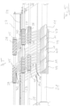
- the two strands 19a, 19b of the lower track 19 each run in a straight line between the input axis 21 and the associated output axis 29, with the upper strand 19a lying at least substantially in a horizontal plane during operation.
- the diameter of the output axis 29 is smaller than the diameter of the input axis 21.
- the intermediate deflection formed by the intermediate deflection axes 23, 25 is arranged approximately in the area of one third - viewed in the longitudinal direction T - of the longitudinal extension of the overlap unit 15 between the input axis 21 and the output axes 27, 29.
- the upper deflection axis 23, which is closer to the output axes 27, 29, is above the output axis 27 of the upper track 17 and above the lower intermediate deflection axis 25, which is closer to the input axis 21 and is located at approximately the same height level as the output axis 27 of the upper track 17.
- both strands 17a, 17b of the upper track 17 run sufficiently far above the upper strand 19a of the lower track 19 for the remaining conveying distance up to the output axis 27.
- the lower strand 17b of the upper track 17 is “pulled upwards” to a certain extent and thus reaches a height level sufficiently far above the upper strand 19a of the lower track 19 earlier than without this intermediate deflection, whereby the "pulling up” of the upper run 17a of the upper track 17 by means of the other intermediate deflection axis 23 ensures that in the input-side area the upper run 17a remains above the lower run 17b of the upper track 17.
- the input-side, lower intermediate deflection axis 25 also causes an offset of the lower run 17b of the upper track 17 in the transverse direction, which will be discussed in more detail below.
- the diameters of the two output axes 27, 28 and their vertical distance are selected such that a portion 11 conveyed on the upper run 19a of the lower track 19 is not hindered, but at the same time a clean depositing of a portion 11 conveyed by means of the upper run 17a of the upper track 17 onto a portion conveyed by means of the lower track 19 is ensured.
- Fig. 3 In particular, the rocker arm 43 carrying the intermediate deflection axes 23, 25 can be seen, which is provided with a scale 51 on which the position of the intermediate deflection axes 23, 25 relative to the base 16 can be read.
- Fig. 3 Also shown on the outlet side is a portion 11 lying on the upper run 19a of the lower track, the height of which is smaller than the vertical distance between the lower run 17b of the upper track 17 and the upper run 19a of the lower track at the outlet end of the overlap unit 15.
- Fig. 4 In particular, it can be seen that, viewed in the longitudinal direction T, for each pair of tracks, the lower track 19 and the upper track 17 run obliquely to the longitudinal direction T and thus in the longitudinal direction T from an inlet-side, side-by-side arrangement towards one another into an outlet-side, laterally overlapping, one above the other arrangement.
- Fig. 5 which shows a perspective partial view approximately in the longitudinal direction T, is particularly the difference in the course of the upper run 17a to the lower run 17b of the upper track 17 and this in relation to the course of the upper run 19a of the lower track 19.
- the lower run 17b is "held away" from the upper run 19a of the lower track in order to ensure sufficient clearance or clearance height for a portion 11 resting on the upper run 19a of the lower track.
- This lateral holding away of the lower run 17b of the upper track also has the advantage that the restoring force of the conveyor belts deflected by the holding away pushes the grooved deflection sleeve 26 in the opposite direction, in Fig. 5 i.e. to the left.
- a fixation is therefore only required on one side, in this case the left side, which in the embodiment shown is provided in the form of a clamping ring 45, which can be fixed in the desired transverse position, for example by means of a screw on the rod forming the deflection axis 25.
- Fig. 6 It can be seen that on the input side up to the first, lower intermediate deflection axis 25 as seen in the longitudinal direction T, the lower run 17b of the upper track 17 does not run parallel to the upper run 17a, but slightly obliquely to the longitudinal direction T in the opposite direction to the upper run 17a, so that the lower run 17b on the input side remains outside the area above the upper run 19a of the lower track 19.
- Fig. 6 It can be seen that the deflection sleeves 47, 49 for the two tracks 17, 19 of each track pair, which are arranged in a rotationally fixed manner on the common drive shaft 21, have a different diameter, which is smaller for the upper track 19 than that for the lower track 17. Due to this larger deflection path on the drive shaft 21 for the upper track 17, the conveyor belts of the upper track 17 run at a higher conveying speed than those of the lower track 19. The difference in diameter is dimensioned such that the resulting difference in the conveying speeds of the two tracks 17, 19 just compensates for the difference in conveying length between the two tracks 17, 19, which is caused by the different course of the upper track 17 relative to the lower track 19. This ensures that in the total portions formed, the portion 11 from the lower track 19 on the one hand and the portion 11 from the upper track 17 on the other hand do not have any offset in the longitudinal direction T.
- a desired longitudinal offset between the portions 11, which is different from zero can be specifically specified by selecting the diameter difference on the common drive shaft 21 or at another location accordingly, thus generally causing a conveying length difference between the two tracks 17, 19 corresponding to the desired longitudinal offset.
- Fig. 7 which shows a front view of the overlap unit 15 according to the invention in a direction opposite to the longitudinal direction T, is, inter alia, the transverse offset of the lower run 17b of the upper track - here in Fig. 7 to the left - opposite the upper run 17a in the inlet side area.
- Fig. 8 shows in particular a cross-section through the common drive shaft 21 at the input end of the overlap unit 15.
- the cross-sectional shape of the grooves of the deflection sleeves 47, 49 is adapted to the cross-section of the conveyor belts 31.
- This cross-section is circular in the embodiment shown here, but other cross-sectional shapes are also possible.
- the transverse fixation and the rotationally fixed coupling of the deflection sleeves 47, 49 on the drive shaft 21 are carried out for each deflection sleeve 47, 49 by means of a clamping screw 33, which engages through an opening in the casing of the deflection sleeve 47, 49 into a transverse groove of the drive shaft 21.
- This type of detachable fixation and thus adjustability of the deflection sleeves 47, 49 in the transverse direction on the drive shaft 21 is also shown in the sectioned partial view of the Fig. 9 to be taken.
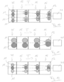
- overlapping units 15 according to the invention, as described above in connection with the Fig. 1 to 9 described, wherein the overlapping units 15 are arranged directly downstream of a conveyor 35, which is in particular the so-called first control belt of a High-speed slicers for the simultaneous slicing of several bar-shaped or loaf-shaped food products arranged next to one another.
- the overlapping units 15 can form a component of the so-called portioning system of the slicer, which includes, among other things, the conveyor 35 shown.
- the overlapping units 15 can each be designed in the form of a cassette and integrated into a frame belonging to the slicer. Installation is preferably carried out at the position of a control belt.
- This "cascade" of overlapping units 15 arranged one after the other in the longitudinal direction T is followed by a further device 41 of basically any design, by means of which the total portions 12 formed by the overlapping unit 15 can be transported further or processed further.
- a further device 41 of basically any design, by means of which the total portions 12 formed by the overlapping unit 15 can be transported further or processed further.
- formats from one or more total portions 12 can be formed on the device 41.
- the further transport of the total portions 12 or the formats formed from them can, for example, take place perpendicular to the longitudinal direction T or further in the longitudinal direction T.
- each portion 11 runs through the conveyor in four tracks lying side by side.
- each portion 11 is shown here in the form of a circular disk.
- Each portion 11 can be, for example, as shown in Fig. 1 comprise a plurality of panes arranged in shingles in the longitudinal direction T.
- first overlapping unit 15 By means of a first overlapping unit 15, the two outer portions are first overlapped laterally, after which these two overlapping portions are brought together by means of a second overlapping unit 15, after which the two inner individual portions are finally overlapped by means of a third overlapping unit 15, thus completing the desired total portion 12.
- portions made of discs with a diameter (caliber) of approximately 60 mm can be laterally overlapped to form a total portion 12 with a portion width of approximately 160 mm in total.
- the portions 11 only run in two lanes, whereby the first two overlapping units 15 are only configured for "passage" and thus the transverse positions of the portions 11 are not changed by these first two overlapping units 15. Only by means of the third and last overlapping unit 15 is the desired total portion 12 formed by lateral overlap. In the application according to Fig. 11 It is therefore sufficient if the overlapping units 15 each have only one track pair with a lower track and an upper track, whereas in the application according to Fig. 10 the overlapping units 15 each have two such track pairs.
- portions with a diameter (caliber) of 100 mm or 90 mm can be laterally overlapped to form a total portion of 12 with a total portion width of 160 mm each.
- Fig. 12 shows that portions 11 arriving in an odd number of tracks can also be handled in the manner according to the invention.
- the three portions 11 arriving next to each other in this application are guided in such a way that the two left portions 11 are first overlapped laterally by means of the first overlapping unit 15, whereas the right portion 11 only passes through in the longitudinal direction T.
- the overlap portion and the right portion are brought together by means of the second overlap unit 15, whereupon the respective total portion 12 is formed by means of the third and last overlap unit 15, in which the portion 11 originally entering on the far right lies with lateral overlap on the middle individual portion.
- portions 11 with a diameter (caliber) of 55 mm can be laterally overlapped to form a total portion 12 with a total portion width of approximately 110 mm.
- the total portions 12 can be formed successively by means of several corresponding overlapping units 15 connected in series in the longitudinal direction T through overlapping processes that take place one after the other at each of the overlapping units 15, wherein, if required, one or more of the overlapping units 15 can either only bring about a lateral merging without an overlapping effect or a mere passage without changing the relative transverse position.
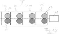
- Fig. 13 shows that several overlapping units 15 arranged one behind the other do not need to be used for lateral overlapping or lateral merging, but can each be configured "for passage".
- the total portion 12 then corresponds to the inlet-side arrangement of the two individual portions 11.
- Fig. 13 an option whereby conventional tape cassettes can be used for simple straight-line transport instead of the overlapping cassettes according to the invention.
Landscapes
- Engineering & Computer Science (AREA)
- Mechanical Engineering (AREA)
- Life Sciences & Earth Sciences (AREA)
- Forests & Forestry (AREA)
- Structure Of Belt Conveyors (AREA)
Priority Applications (1)
| Application Number | Priority Date | Filing Date | Title |
|---|---|---|---|
| EP20154531.6A EP3689563B1 (de) | 2015-03-18 | 2016-03-08 | Überlappungseinheit zum seitlichen überlappen von in einer längsrichtung transportierten portionen |
Applications Claiming Priority (1)
| Application Number | Priority Date | Filing Date | Title |
|---|---|---|---|
| DE102015104055.7A DE102015104055A1 (de) | 2015-03-18 | 2015-03-18 | Überlappungsvorrichtung |
Related Child Applications (2)
| Application Number | Title | Priority Date | Filing Date |
|---|---|---|---|
| EP20154531.6A Division EP3689563B1 (de) | 2015-03-18 | 2016-03-08 | Überlappungseinheit zum seitlichen überlappen von in einer längsrichtung transportierten portionen |
| EP20154531.6A Division-Into EP3689563B1 (de) | 2015-03-18 | 2016-03-08 | Überlappungseinheit zum seitlichen überlappen von in einer längsrichtung transportierten portionen |
Publications (3)
| Publication Number | Publication Date |
|---|---|
| EP3069836A1 EP3069836A1 (de) | 2016-09-21 |
| EP3069836B1 true EP3069836B1 (de) | 2024-10-30 |
| EP3069836C0 EP3069836C0 (de) | 2024-10-30 |
Family
ID=55661126
Family Applications (2)
| Application Number | Title | Priority Date | Filing Date |
|---|---|---|---|
| EP16159140.9A Active EP3069836B1 (de) | 2015-03-18 | 2016-03-08 | Überlappungsvorrichtung |
| EP20154531.6A Active EP3689563B1 (de) | 2015-03-18 | 2016-03-08 | Überlappungseinheit zum seitlichen überlappen von in einer längsrichtung transportierten portionen |
Family Applications After (1)
| Application Number | Title | Priority Date | Filing Date |
|---|---|---|---|
| EP20154531.6A Active EP3689563B1 (de) | 2015-03-18 | 2016-03-08 | Überlappungseinheit zum seitlichen überlappen von in einer längsrichtung transportierten portionen |
Country Status (5)
| Country | Link |
|---|---|
| US (2) | US9809401B2 (pl) |
| EP (2) | EP3069836B1 (pl) |
| DE (1) | DE102015104055A1 (pl) |
| ES (2) | ES3049429T3 (pl) |
| PL (1) | PL3069836T3 (pl) |
Families Citing this family (18)
| Publication number | Priority date | Publication date | Assignee | Title |
|---|---|---|---|---|
| DE102015104055A1 (de) | 2015-03-18 | 2016-09-22 | Textor Maschinenbau GmbH | Überlappungsvorrichtung |
| DE102017100620A1 (de) * | 2017-01-13 | 2018-07-19 | Weber Maschinenbau Gmbh Breidenbach | Produktgreifer |
| DE102017118934A1 (de) * | 2017-07-03 | 2019-01-03 | Weber Maschinenbau Gmbh Breidenbach | Bereitstellen von bahnförmigem Zwischenblattmaterial an einem Schneidbereich |
| DE102017118930A1 (de) * | 2017-07-03 | 2019-01-03 | Weber Maschinenbau Gmbh Breidenbach | Bereitstellen von bahnförmigem Zwischenblattmaterial an einem Schneidbereich |
| EP3424852B1 (de) * | 2017-07-03 | 2021-04-21 | Weber Maschinenbau GmbH Breidenbach | Bereitstellen von bahnförmigem zwischenblattmaterial an einem schneidbereich |
| DE102017118925A1 (de) * | 2017-07-03 | 2019-01-03 | Weber Maschinenbau Gmbh Breidenbach | Bereitstellen von bahnförmigem Zwischenblattmaterial an einem Schneidbereich |
| EP3888467A1 (de) * | 2017-07-03 | 2021-10-06 | Weber Maschinenbau GmbH Breidenbach | Bereitstellen von bahnförmigem zwischenblattmaterial an einem schneidbereich |
| DE102017118927A1 (de) * | 2017-07-03 | 2019-01-03 | Weber Maschinenbau Gmbh Breidenbach | Bereitstellen von bahnförmigem Zwischenblattmaterial an einem Schneidbereich |
| DE102017125110A1 (de) | 2017-10-26 | 2019-05-02 | Weber Maschinenbau Gmbh Breidenbach | Fördereinrichtung |
| DE102018102919C5 (de) | 2018-02-09 | 2026-04-09 | Provisur Technologies, Inc. | Fördereinrichtung zur Förderung von Lebensmittelprodukten und zugehöriges Betriebsverfahren |
| DE102019108126A1 (de) * | 2019-03-28 | 2020-10-01 | Weber Maschinenbau Gmbh Breidenbach | Vorrichtung zum Fördern von Produkten |
| IT201900007812A1 (it) * | 2019-06-03 | 2020-12-03 | Plusline S R L | Gruppo per l'alimentazione di film di materiale plastico. |
| DE102020129750A1 (de) | 2020-11-11 | 2022-05-12 | Multivac Sepp Haggenmüller Se & Co. Kg | Verfahren zum Quer-Positionieren eines zu transportierenden Artikels |
| IT202100013481A1 (it) | 2021-05-25 | 2022-11-25 | Elcat S R L | Gruppo configurabile per il convogliamento di prodotti, in particolare prodotti alimentari affettati |
| EP4347454A1 (de) * | 2021-05-31 | 2024-04-10 | Körber Supply Chain Logistics GmbH | Verjüngung eines förderstroms von stückgütern |
| US20230125230A1 (en) | 2021-10-25 | 2023-04-27 | Provisur Technologies, Inc. | Pivoting loading tray assembly for food product slicing apparatus and method of use |
| DE102022121774A1 (de) * | 2022-08-29 | 2024-02-29 | Multivac Sepp Haggenmüller Se & Co. Kg | Verfahren zum automatischen Einhalten einer vorgegebenen Portions-Anordnung in einer Tray-Mulde sowie hierfür geeignete Verpackungs-Vorrichtung |
| DE102023104700A1 (de) * | 2023-02-27 | 2024-08-29 | Schindler Holding GmbH & Co. KG | Achse bzw. Welle |
Family Cites Families (11)
| Publication number | Priority date | Publication date | Assignee | Title |
|---|---|---|---|---|
| US4645061A (en) * | 1985-02-26 | 1987-02-24 | Welch Hubert E | Machine for stacking nestable extruded cans |
| DE3642123A1 (de) * | 1986-12-10 | 1988-06-16 | Thurne Gmbh | Einrichtung zum ablegen von scheibenfoermigen nahrungsmittelprodukten |
| EP0274229B1 (en) * | 1986-12-10 | 1991-10-02 | Thurne Engineering Co Ltd | Conveyor system |
| US5566600A (en) * | 1994-10-11 | 1996-10-22 | Formax, Inc. | Conveyor/classifier system for versatile hi-speed food loaf slicing machine |
| US5810149A (en) * | 1996-11-26 | 1998-09-22 | Formax, Inc. | Conveyor system |
| US6763748B2 (en) | 2002-07-26 | 2004-07-20 | Formax, Inc. | Automatic draft length compensation for slicing machine system |
| US6935215B2 (en) * | 2002-08-14 | 2005-08-30 | Formax, Inc. | Slicing machine and conveyor system with automatic product width compensation |
| US7114609B2 (en) * | 2005-02-08 | 2006-10-03 | Paper Converting Machine Company | Product diverter and method |
| DE102013206510A1 (de) | 2012-12-03 | 2014-06-05 | Textor Maschinenbau GmbH | Hochleistungsaufschnittschneidemaschine mit zumindest einer entnehmbaren Bandkassette |
| DE102013113199A1 (de) * | 2013-11-28 | 2015-05-28 | Textor Maschinenbau GmbH | Vorrichtung und Verfahren zum Erstellen von Formatsätzen aus Kombinationsportionen |
| DE102015104055A1 (de) | 2015-03-18 | 2016-09-22 | Textor Maschinenbau GmbH | Überlappungsvorrichtung |
-
2015
- 2015-03-18 DE DE102015104055.7A patent/DE102015104055A1/de active Pending
-
2016
- 2016-03-08 EP EP16159140.9A patent/EP3069836B1/de active Active
- 2016-03-08 PL PL16159140.9T patent/PL3069836T3/pl unknown
- 2016-03-08 EP EP20154531.6A patent/EP3689563B1/de active Active
- 2016-03-08 ES ES20154531T patent/ES3049429T3/es active Active
- 2016-03-08 ES ES16159140T patent/ES2998037T3/es active Active
- 2016-03-14 US US15/069,318 patent/US9809401B2/en active Active
-
2017
- 2017-09-20 US US15/710,437 patent/US10065335B2/en active Active
Also Published As
| Publication number | Publication date |
|---|---|
| DE102015104055A1 (de) | 2016-09-22 |
| EP3689563B1 (de) | 2025-09-10 |
| US10065335B2 (en) | 2018-09-04 |
| US20180037423A1 (en) | 2018-02-08 |
| US20160272440A1 (en) | 2016-09-22 |
| US9809401B2 (en) | 2017-11-07 |
| ES2998037T3 (en) | 2025-02-18 |
| EP3689563A1 (de) | 2020-08-05 |
| PL3069836T3 (pl) | 2025-03-24 |
| ES3049429T3 (en) | 2025-12-16 |
| EP3069836A1 (de) | 2016-09-21 |
| EP3069836C0 (de) | 2024-10-30 |
Similar Documents
| Publication | Publication Date | Title |
|---|---|---|
| EP3069836B1 (de) | Überlappungsvorrichtung | |
| DE2803223C2 (pl) | ||
| EP2671829B1 (de) | Spreizeinrichtung | |
| DE69934375T2 (de) | Anlage zum Herstellen und Verpacken von rollenförmigen Gegenständen | |
| WO1988000113A1 (en) | Circular cross-cut saw for cutting boards to length | |
| DE19819736C1 (de) | Vorrichtung zum Übereinanderlegen von Papierblättern oder dgl. | |
| EP0941817A1 (de) | Schneidmaschine zum selbsttätigen Beschneiden von Druckerzeugnissen wie Broschuren, Zeitschriften oder Büchern | |
| EP1166977A1 (de) | Schneidmaschine zum selbsttätigen Beschneiden von Druckerzeugnissen | |
| DE102004034256A1 (de) | Vorrichtung zum Schneiden von Blech | |
| EP4032669A1 (de) | Mehrspurige aufschneide-maschine mit unabhängig ansteuerbaren greifern | |
| EP2581331A1 (de) | Vorrichtung und Verfahren zum Ausrichten von Produkten | |
| EP0698451A1 (de) | Verfahren und Einrichtung zum Beschneiden von flachen Druckprodukten längs einer vorgegebenen Schnittlinie | |
| EP2982622B1 (de) | Vorrichtung zum verteilen eines stroms von produkten | |
| EP2743193A1 (de) | Verfahren und Vorrichtung zum Falten oder Wenden einer Scheibe oder einer Portion eines aufgeschnittenen Lebensmittelprodukts | |
| EP4001187A1 (de) | Verfahren zum quer-positionieren eines zu transportierenden artikels | |
| EP1351783A1 (de) | Vorrichtung zum querteilen von metallbändern | |
| DE102015115299B4 (de) | Vorrichtung zur seitlichen Beaufschlagung eines Teigbandes oder Teigstückes | |
| DE60028163T2 (de) | Vorrichtung zum Zuführen von Zigarren | |
| EP3046842B1 (de) | Vorrichtung zur herstellung von verpackungseinheiten | |
| EP4001182A1 (de) | Verpackungsmaschine sowie vorrichtung und verfahren zum trassieren einer transportstrecke einer verpackungsmaschine | |
| DE19963398A1 (de) | Fördersystem | |
| DE19738159A1 (de) | Verfahren und Vorrichtung zum Verteilen des Produktstromes | |
| DE3837201A1 (de) | Zweistrang-zigaretten-fertigungsmaschine | |
| EP3067173A1 (de) | Aufschneidevorrichtung | |
| DE102004010334A1 (de) | Verfahren zum Sägen von Hölzern |
Legal Events
| Date | Code | Title | Description |
|---|---|---|---|
| PUAI | Public reference made under article 153(3) epc to a published international application that has entered the european phase |
Free format text: ORIGINAL CODE: 0009012 |
|
| AK | Designated contracting states |
Kind code of ref document: A1 Designated state(s): AL AT BE BG CH CY CZ DE DK EE ES FI FR GB GR HR HU IE IS IT LI LT LU LV MC MK MT NL NO PL PT RO RS SE SI SK SM TR |
|
| AX | Request for extension of the european patent |
Extension state: BA ME |
|
| STAA | Information on the status of an ep patent application or granted ep patent |
Free format text: STATUS: REQUEST FOR EXAMINATION WAS MADE |
|
| 17P | Request for examination filed |
Effective date: 20170320 |
|
| RBV | Designated contracting states (corrected) |
Designated state(s): AL AT BE BG CH CY CZ DE DK EE ES FI FR GB GR HR HU IE IS IT LI LT LU LV MC MK MT NL NO PL PT RO RS SE SI SK SM TR |
|
| STAA | Information on the status of an ep patent application or granted ep patent |
Free format text: STATUS: EXAMINATION IS IN PROGRESS |
|
| 17Q | First examination report despatched |
Effective date: 20170821 |
|
| P01 | Opt-out of the competence of the unified patent court (upc) registered |
Effective date: 20230522 |
|
| GRAP | Despatch of communication of intention to grant a patent |
Free format text: ORIGINAL CODE: EPIDOSNIGR1 |
|
| STAA | Information on the status of an ep patent application or granted ep patent |
Free format text: STATUS: GRANT OF PATENT IS INTENDED |
|
| INTG | Intention to grant announced |
Effective date: 20240801 |
|
| GRAS | Grant fee paid |
Free format text: ORIGINAL CODE: EPIDOSNIGR3 |
|
| GRAA | (expected) grant |
Free format text: ORIGINAL CODE: 0009210 |
|
| STAA | Information on the status of an ep patent application or granted ep patent |
Free format text: STATUS: THE PATENT HAS BEEN GRANTED |
|
| AK | Designated contracting states |
Kind code of ref document: B1 Designated state(s): AL AT BE BG CH CY CZ DE DK EE ES FI FR GB GR HR HU IE IS IT LI LT LU LV MC MK MT NL NO PL PT RO RS SE SI SK SM TR |
|
| REG | Reference to a national code |
Ref country code: GB Ref legal event code: FG4D Free format text: NOT ENGLISH |
|
| REG | Reference to a national code |
Ref country code: CH Ref legal event code: EP |
|
| REG | Reference to a national code |
Ref country code: DE Ref legal event code: R096 Ref document number: 502016016768 Country of ref document: DE |
|
| REG | Reference to a national code |
Ref country code: IE Ref legal event code: FG4D Free format text: LANGUAGE OF EP DOCUMENT: GERMAN |
|
| U01 | Request for unitary effect filed |
Effective date: 20241030 |
|
| U07 | Unitary effect registered |
Designated state(s): AT BE BG DE DK EE FI FR IT LT LU LV MT NL PT RO SE SI Effective date: 20241106 |
|
| P04 | Withdrawal of opt-out of the competence of the unified patent court (upc) registered |
Free format text: CASE NUMBER: APP_59477/2024 Effective date: 20241101 |
|
| REG | Reference to a national code |
Ref country code: ES Ref legal event code: FG2A Ref document number: 2998037 Country of ref document: ES Kind code of ref document: T3 Effective date: 20250218 |
|
| PG25 | Lapsed in a contracting state [announced via postgrant information from national office to epo] |
Ref country code: IS Free format text: LAPSE BECAUSE OF FAILURE TO SUBMIT A TRANSLATION OF THE DESCRIPTION OR TO PAY THE FEE WITHIN THE PRESCRIBED TIME-LIMIT Effective date: 20250228 Ref country code: HR Free format text: LAPSE BECAUSE OF FAILURE TO SUBMIT A TRANSLATION OF THE DESCRIPTION OR TO PAY THE FEE WITHIN THE PRESCRIBED TIME-LIMIT Effective date: 20241030 |
|
| PG25 | Lapsed in a contracting state [announced via postgrant information from national office to epo] |
Ref country code: NO Free format text: LAPSE BECAUSE OF FAILURE TO SUBMIT A TRANSLATION OF THE DESCRIPTION OR TO PAY THE FEE WITHIN THE PRESCRIBED TIME-LIMIT Effective date: 20250130 |
|
| PG25 | Lapsed in a contracting state [announced via postgrant information from national office to epo] |
Ref country code: GR Free format text: LAPSE BECAUSE OF FAILURE TO SUBMIT A TRANSLATION OF THE DESCRIPTION OR TO PAY THE FEE WITHIN THE PRESCRIBED TIME-LIMIT Effective date: 20250131 |
|
| PG25 | Lapsed in a contracting state [announced via postgrant information from national office to epo] |
Ref country code: RS Free format text: LAPSE BECAUSE OF FAILURE TO SUBMIT A TRANSLATION OF THE DESCRIPTION OR TO PAY THE FEE WITHIN THE PRESCRIBED TIME-LIMIT Effective date: 20250130 |
|
| U21 | Renewal fee for the european patent with unitary effect paid with additional fee |
Year of fee payment: 10 Effective date: 20250516 |
|
| PG25 | Lapsed in a contracting state [announced via postgrant information from national office to epo] |
Ref country code: SM Free format text: LAPSE BECAUSE OF FAILURE TO SUBMIT A TRANSLATION OF THE DESCRIPTION OR TO PAY THE FEE WITHIN THE PRESCRIBED TIME-LIMIT Effective date: 20241030 |
|
| PGFP | Annual fee paid to national office [announced via postgrant information from national office to epo] |
Ref country code: ES Payment date: 20250416 Year of fee payment: 10 |
|
| PGFP | Annual fee paid to national office [announced via postgrant information from national office to epo] |
Ref country code: CH Payment date: 20250401 Year of fee payment: 10 |
|
| PG25 | Lapsed in a contracting state [announced via postgrant information from national office to epo] |
Ref country code: SK Free format text: LAPSE BECAUSE OF FAILURE TO SUBMIT A TRANSLATION OF THE DESCRIPTION OR TO PAY THE FEE WITHIN THE PRESCRIBED TIME-LIMIT Effective date: 20241030 |
|
| PG25 | Lapsed in a contracting state [announced via postgrant information from national office to epo] |
Ref country code: CZ Free format text: LAPSE BECAUSE OF FAILURE TO SUBMIT A TRANSLATION OF THE DESCRIPTION OR TO PAY THE FEE WITHIN THE PRESCRIBED TIME-LIMIT Effective date: 20241030 |
|
| PLBE | No opposition filed within time limit |
Free format text: ORIGINAL CODE: 0009261 |
|
| STAA | Information on the status of an ep patent application or granted ep patent |
Free format text: STATUS: NO OPPOSITION FILED WITHIN TIME LIMIT |
|
| 26N | No opposition filed |
Effective date: 20250731 |
|
| PG25 | Lapsed in a contracting state [announced via postgrant information from national office to epo] |
Ref country code: MC Free format text: LAPSE BECAUSE OF FAILURE TO SUBMIT A TRANSLATION OF THE DESCRIPTION OR TO PAY THE FEE WITHIN THE PRESCRIBED TIME-LIMIT Effective date: 20241030 |
|
| PG25 | Lapsed in a contracting state [announced via postgrant information from national office to epo] |
Ref country code: IE Free format text: LAPSE BECAUSE OF NON-PAYMENT OF DUE FEES Effective date: 20250308 |
|
| REG | Reference to a national code |
Ref country code: CH Ref legal event code: U11 Free format text: ST27 STATUS EVENT CODE: U-0-0-U10-U11 (AS PROVIDED BY THE NATIONAL OFFICE) Effective date: 20260401 |
|
| PGFP | Annual fee paid to national office [announced via postgrant information from national office to epo] |
Ref country code: GB Payment date: 20260324 Year of fee payment: 11 |
|
| PGFP | Annual fee paid to national office [announced via postgrant information from national office to epo] |
Ref country code: PL Payment date: 20260227 Year of fee payment: 11 |