EP3068032A1 - Electric power tool - Google Patents
Electric power tool Download PDFInfo
- Publication number
- EP3068032A1 EP3068032A1 EP16161572.9A EP16161572A EP3068032A1 EP 3068032 A1 EP3068032 A1 EP 3068032A1 EP 16161572 A EP16161572 A EP 16161572A EP 3068032 A1 EP3068032 A1 EP 3068032A1
- Authority
- EP
- European Patent Office
- Prior art keywords
- voltage
- current
- motor
- brushless motor
- electric power
- Prior art date
- Legal status (The legal status is an assumption and is not a legal conclusion. Google has not performed a legal analysis and makes no representation as to the accuracy of the status listed.)
- Granted
Links
Images


Classifications
-
- H—ELECTRICITY
- H02—GENERATION; CONVERSION OR DISTRIBUTION OF ELECTRIC POWER
- H02P—CONTROL OR REGULATION OF ELECTRIC MOTORS, ELECTRIC GENERATORS OR DYNAMO-ELECTRIC CONVERTERS; CONTROLLING TRANSFORMERS, REACTORS OR CHOKE COILS
- H02P27/00—Arrangements or methods for the control of AC motors characterised by the kind of supply voltage
- H02P27/04—Arrangements or methods for the control of AC motors characterised by the kind of supply voltage using variable-frequency supply voltage, e.g. inverter or converter supply voltage
- H02P27/06—Arrangements or methods for the control of AC motors characterised by the kind of supply voltage using variable-frequency supply voltage, e.g. inverter or converter supply voltage using dc to ac converters or inverters
-
- H—ELECTRICITY
- H02—GENERATION; CONVERSION OR DISTRIBUTION OF ELECTRIC POWER
- H02P—CONTROL OR REGULATION OF ELECTRIC MOTORS, ELECTRIC GENERATORS OR DYNAMO-ELECTRIC CONVERTERS; CONTROLLING TRANSFORMERS, REACTORS OR CHOKE COILS
- H02P6/00—Arrangements for controlling synchronous motors or other dynamo-electric motors using electronic commutation dependent on the rotor position; Electronic commutators therefor
- H02P6/14—Electronic commutators
- H02P6/15—Controlling commutation time
-
- H—ELECTRICITY
- H02—GENERATION; CONVERSION OR DISTRIBUTION OF ELECTRIC POWER
- H02K—DYNAMO-ELECTRIC MACHINES
- H02K19/00—Synchronous motors or generators
- H02K19/02—Synchronous motors
- H02K19/10—Synchronous motors for multi-phase current
-
- H—ELECTRICITY
- H02—GENERATION; CONVERSION OR DISTRIBUTION OF ELECTRIC POWER
- H02P—CONTROL OR REGULATION OF ELECTRIC MOTORS, ELECTRIC GENERATORS OR DYNAMO-ELECTRIC CONVERTERS; CONTROLLING TRANSFORMERS, REACTORS OR CHOKE COILS
- H02P27/00—Arrangements or methods for the control of AC motors characterised by the kind of supply voltage
- H02P27/04—Arrangements or methods for the control of AC motors characterised by the kind of supply voltage using variable-frequency supply voltage, e.g. inverter or converter supply voltage
-
- H—ELECTRICITY
- H02—GENERATION; CONVERSION OR DISTRIBUTION OF ELECTRIC POWER
- H02P—CONTROL OR REGULATION OF ELECTRIC MOTORS, ELECTRIC GENERATORS OR DYNAMO-ELECTRIC CONVERTERS; CONTROLLING TRANSFORMERS, REACTORS OR CHOKE COILS
- H02P6/00—Arrangements for controlling synchronous motors or other dynamo-electric motors using electronic commutation dependent on the rotor position; Electronic commutators therefor
- H02P6/10—Arrangements for controlling torque ripple, e.g. providing reduced torque ripple
-
- H—ELECTRICITY
- H02—GENERATION; CONVERSION OR DISTRIBUTION OF ELECTRIC POWER
- H02P—CONTROL OR REGULATION OF ELECTRIC MOTORS, ELECTRIC GENERATORS OR DYNAMO-ELECTRIC CONVERTERS; CONTROLLING TRANSFORMERS, REACTORS OR CHOKE COILS
- H02P6/00—Arrangements for controlling synchronous motors or other dynamo-electric motors using electronic commutation dependent on the rotor position; Electronic commutators therefor
- H02P6/14—Electronic commutators
- H02P6/15—Controlling commutation time
- H02P6/157—Controlling commutation time wherein the commutation is function of electro-magnetic force [EMF]
-
- H—ELECTRICITY
- H02—GENERATION; CONVERSION OR DISTRIBUTION OF ELECTRIC POWER
- H02P—CONTROL OR REGULATION OF ELECTRIC MOTORS, ELECTRIC GENERATORS OR DYNAMO-ELECTRIC CONVERTERS; CONTROLLING TRANSFORMERS, REACTORS OR CHOKE COILS
- H02P6/00—Arrangements for controlling synchronous motors or other dynamo-electric motors using electronic commutation dependent on the rotor position; Electronic commutators therefor
- H02P6/28—Arrangements for controlling current
Definitions
- the invention relates to an electric power tool.
- Japanese Patent Publication No. 4487836 discloses an electric device that controls a motor with an inverter circuit to operate an end tool connected to the motor.
- the above conventional electric power tool includes a smoothing capacitor having large capacity, power factor of AC power is deteriorated.
- an electric power tool equipping with a power-factor improvement circuit can be also conceived.
- such configuration increases the size of the electric power tool and increases the cost.
- the invention provides an electric power tool including: a brushless motor having a plurality of stator windings and configured to rotate in accordance with voltages applied to the plurality of stator windings, an induced voltage being generated in accordance with a rotation of the brushless motor; a rectifier circuit configured to rectify an AC voltage; a smoothing capacitor configured to smooth the AC voltage rectified by the rectifier circuit to a pulsation voltage having a maximum value larger than the induced voltage and a minimum value smaller than the induced voltage; and an inverter circuit configured to perform switching operations to output the pulsation voltage to the plurality of stator windings by rotation.
- the electric power tool further includes: a receiving unit configured to receive an instruction for the inverter circuit to perform the switching operations; and a control unit configured to control the inverter circuit to continue to perform the switching operations while the receiving unit is receiving the instruction, even if the pulsation voltage is smaller than the induced voltage.
- control unit prevents the inverter circuit from performing the switching operations when a current flowing through the brushless motor is larger than an overcurrent threshold.
- an electric power tool including: a brushless motor including: a stator having a plurality of stator windings to which an AC voltage is applied from an AC power source; and a rotor rotatable for the stator; an end tool that is driven in accordance with the rotation of the rotor; an inverter circuit configured to perform switching operations to output the pulsation voltage to the plurality of stator windings by rotation, even if the AC voltage is smaller than a preset voltage.
- a brushless motor including: a stator having a plurality of stator windings to which an AC voltage is applied from an AC power source; and a rotor rotatable for the stator; an end tool that is driven in accordance with the rotation of the rotor; an inverter circuit configured to perform switching operations to output the pulsation voltage to the plurality of stator windings by rotation, even if the AC voltage is smaller than a preset voltage.
- an electric power tool including: a motor; a voltage supplying unit configured to supply a drive voltage to the motor; a current detecting circuit configured to detect a current flowing through the motor; and a control unit configured to control the voltage supplying unit to decrease the drive voltage when the current detected by the current detecting circuit is larger than a first current.
- control unit controls the voltage supplying unit to stop supplying the drive voltage when the current detected by the current detecting circuit is larger than a second current larger than the first current.
- the voltage supplying unit supplies a pulsation voltage including a plurality of ripples as the drive voltage to the motor.
- the current detecting circuit detects a peak of the current flowing through the motor.
- the control unit controls the voltage supplying unit to decrease the drive voltage when the peak detected by the current detecting circuit is larger than the first current, keep the decreased drive voltage until a next peak is detected, and increases the decreased drive voltage stepwise if the next peak is smaller than the first current.
- the voltage supplying unit includes an inverter circuit.
- an electric power tool including: a motor; a voltage supplying unit configured to supply a drive voltage set to a target voltage to the motor; a rotational speed detecting circuit configured to detect a rotational speed of the motor; and a control unit configure to change the target voltage based on the rotational speed detected by the rotational speed detecting unit.
- an electric power tool including: a power cable connectable to an AC power source; a brushless motor that is rotated with a power supplied from the AC power source; an end tool that is driven in accordance with the rotation of the brushless motor; a current detecting circuit configured to detect a current flowing through the brushless motor; and a control unit configured to decrease a drive voltage of the brushless motor when the current detected by the current detecting circuit is larger than a preset current value.
- control unit gradually decreases the drive voltage when the current detected by the current detecting circuit is larger than the preset current value.
- control unit performs a PWM control to decrease the drive voltage.
- the control unit performs the PWM control with a duty smaller than 100% when the current detected by the current detecting circuit is larger than the preset current value.
- the control unit performs the PWM control with a duty of 100% when the current detected by the current detecting circuit is smaller than the preset current value.
- an electric power tool including: a power cable connectable to an AC power source; a brushless motor that is rotated with an AC power supplied from the AC power source, a pulsation current flowing through the brushless motor with the AC power; an end tool that is driven in accordance with the rotation of the brushless motor; a current detecting circuit configured to detect the pulsation current flowing through the brushless motor; and a restraining unit configured to retrain a peak of the pulsation current flowing through the brushless motor.
- the restraining unit performs a PWM control to retrain a peak of the pulsation current flowing through the brushless motor.
- an electric power tool including: a motor; a voltage supplying unit configured to generate a drive voltage from a DC voltage and supply the drive voltage to the motor; a voltage detecting circuit configured to detect the DC voltage; and a control unit configured to prohibit the voltage supplying unit from supplying the drive voltage to the motor when the DC voltage detected by the voltage detecting circuit is outside a preset range.
- an electric power tool including: a motor; a rectifier circuit configured to convert an AC voltage into a rectified voltage; a voltage supplying unit configured to generate a drive voltage from the rectified voltage and supply the drive voltage to the motor; a voltage detecting circuit configured to detect the rectified voltage; and a control unit configured to prohibit the voltage supplying unit from supplying the drive voltage to the motor when the rectified voltage detected by the voltage detecting circuit is outside a preset range.
- the voltage detecting circuit detects a peak of the rectified voltage.
- the control unit prohibits the voltage supplying unit from supplying the drive voltage to the motor when the rectified voltage detected by the voltage detecting circuit is outside the preset range.
- an electric power tool including: a power cable connectable to an AC power source; a voltage supplying unit configured to generate a drive voltage from the power supplied from the AC power source; a brushless motor that is rotated with the drive voltage; an end tool that is driven in accordance with the rotation of the brushless motor; a current detecting circuit configured to detect a current flowing through the brushless motor; and a control unit configured to perform a PWM control to control the voltage supplying unit.
- the control unit determines a duty of the PWM control based on a difference between the current detected by the current detecting circuit and a first current value when the current detected by the current detecting circuit is larger than the first current value.
- an electric power tool including: a power cable connectable to an AC power source; a voltage supplying unit configured to generate a drive voltage from the power supplied from the AC power source; a brushless motor that is rotated with the drive voltage; an end tool that is driven in accordance with the rotation of the brushless motor; a current detecting circuit configured to detect a current flowing through the brushless motor; and a control unit configured to perform a PWM control to control the voltage supplying unit.
- the control unit decreases a duty of the PWM control when the drive voltage is larger than a first voltage value.
- an electric power tool including: a power cable connectable to an AC power source; a voltage supplying unit configured to generate a drive voltage from the power supplied from the AC power source; a brushless motor that is rotated with the drive voltage; an end tool that is driven in accordance with the rotation of the brushless motor; a voltage detecting circuit configured to detect the drive voltage; and a control unit configured to perform a PWM control to control the voltage supplying unit.
- the control unit determines a duty of the PWM control based on a difference between the voltage detected by the voltage detecting circuit and a first voltage value when the voltage detected by the voltage circuit is larger than the first voltage value.
- Fig. 1 is a circuit diagram of the electric power tool 1A according to the first embodiment.
- the power tool 1 includes a trigger switch (the receiving unit of the present invention) 3, a control-circuit-voltage supplying circuit (referred as "CVS" in Fig. 1 ) 4, a motor 5, rotor-position detecting elements 6, a controller 7, an inverter circuit (the inverter circuit and the voltage supplying unit of the present invention) 8, a normal-mode filter 9, a rectifier circuit 10, and a smoothing capacitor 11.
- a trigger switch the receiving unit of the present invention
- CVS control-circuit-voltage supplying circuit
- the control-circuit-voltage supplying circuit 4 When the trigger switch 3 is operated, AC voltage outputted from a commercial power source 2 is rectified and smoothed by the rectifier circuit 10 and the smoothing capacitor 11, and is supplied to the motor 5 via the inverter circuit 8. Further, when the trigger switch 3 is operated, the control-circuit-voltage supplying circuit 4 generates a control-circuit driving voltage (15V in the present embodiment) and supplies the control-circuit driving voltage to the controller 7.
- the motor 5 is a three-phase brushless DC motor, and includes a rotor 5A and a stator 5B.
- the rotor 5A is made of a permanent magnet including a plurality of sets (two sets in the present embodiment) of N poles and S poles.
- the stator 5B is made of three-phase stator windings U, V, and W that are connected by star connection.
- the motor 5 (the rotor 5A) rotates by sequentially switching the stator windings U, V, and W through which current flows. Switching of the stator windings U, V, and W will be described later.
- the rotor-position detecting elements 6 are arranged at positions confronting the permanent magnet of the rotor 5A with a predetermined interval (for example, an angle of 60 degrees) in the circumferential direction of the rotor 5A.
- the rotor-position detecting elements 6 output a signal in accordance with rotational position of the rotor 6A.
- the controller 7 includes a motor-current detecting circuit (the current detecting unit of the present invention) (referred as “MCD” in Fig. 1 ) 71, a rectified-voltage detecting circuit (the voltage detecting unit of the present invention) (referred as “RVD” in Fig. 1 ) 72, a control-circuit-voltage detecting circuit (referred as “CVD” in Fig. 1 ) 73, a switch-operation detecting circuit (referred as “SOD” in Fig. 1 ) 74, an applied-voltage setting circuit (referred as “AVS” in Fig. 1 ) 75, a rotor-position detecting circuit (referred as "RPD” in Fig.
- MCD motor-current detecting circuit
- RVD rectified-voltage detecting circuit
- CVD control-circuit-voltage detecting circuit
- SOD switch-operation detecting circuit
- AVS applied-voltage setting circuit
- RPD rotor-position detecting circuit
- a motor-rotational-speed detecting circuit (the rotational speed detecting unit of the present invention) (referred as “RSD” in Fig. 1 ) 77
- an arithmetic section (the control unit of the present invention) 78
- a control-signal outputting circuit (referred as "CSO” in Fig. 1 ) 79
- an AC-input-voltage detecting circuit (referred as "AVD” in Fig. 1 ) 80.
- the AC-input-voltage detecting circuit 80 detects a peak value of AC voltage outputted from the commercial power source 2, and outputs the peak value to the arithmetic section 78.
- AC voltage is detected in a sampling period that a value sufficiently close to the actual peak value can be detected.
- the motor-current detecting circuit 71 detects current supplied to the motor 5, and outputs the current to the arithmetic section 78.
- the rectified-voltage detecting circuit 72 detects voltage outputted from the rectifier circuit 10 and the smoothing capacitor 11, and outputs the voltage to the arithmetic section 78.
- the control-circuit-voltage detecting circuit 73 detects control-circuit driving voltage supplied from the control-circuit-voltage supplying circuit 4, and outputs the driving voltage to the arithmetic section 78.
- the switch-operation detecting circuit 74 detects whether the trigger switch 3 is operated, and outputs the detection result to the arithmetic section 78.
- the applied-voltage setting circuit 75 detects operation amount of the trigger switch 3, and outputs the operation amount to the arithmetic section 78.
- the rotor-position detecting circuit 76 detects rotational position of the rotor 6A based on signals from the rotor-position detecting elements 6, and outputs the rotational position to the motor-rotational-speed detecting circuit 77 and the arithmetic section 78.
- the motor-rotational-speed detecting circuit 77 detects rotational speed of the rotor 6A based on signals from the rotor-position detecting circuit 76, and outputs the rotational speed to the arithmetic section 78.
- the arithmetic section 78 generates switching signals H1-H6 based on signals from the rotor-position detecting circuit 76 and from the motor-rotational-speed detecting circuit 77, and outputs the switching signals H1-H6 to the control-signal outputting circuit 79. Further, the arithmetic section 78 adjusts switching signals H4-H6 as pulse width modulation signal (PWM signal) based on signals from the applied-voltage setting circuit 75, and outputs the PWM signal to the control-signal outputting circuit 79. The switching signals H1-H6 are outputted to the inverter circuit 8 via the control-signal outputting circuit 79. Note that the controller 7 may be so configured to adjust the switching signals H1-H3 as PWM signals.
- the inverter circuit 8 includes switching elements Q1-Q6. Each gate of the switching elements Q1-Q6 is connected with the control-signal outputting circuit 79, and each drain or source of the switching elements Q1-Q6 is connected with the stator windings U, V, and W of the stator 5B.
- the switching elements Q1-Q6 performs switching operations based on the switching signals H1-H6 inputted from the control-signal outputting circuit 79, changes DC voltage of the battery pack 20 applied to the inverter circuit 8 into three-phase (U-phase, V-phase, and W-phase) voltages Vu, Vv, and Vw, and supplies the three-phase voltages Vu, Vv, and Vw to the stator windings U, V, and W, respectively.
- the switching signals H1-H6 are inputted to the switching elements Q1-Q6, respectively.
- the energized stator windings U, V, and W that is, the rotational direction of the rotor 5A is controlled.
- amount of electric power supplied to the stator windings U, V, and W is controlled with the switching signals H4-H6 which are also PWM signals.
- the electric power tool 1A can supply the motor 5 with driving voltage in accordance with the operation amount of the trigger switch 3.
- a conventional electric power tool includes a smoothing capacitor having large capacity, power factor of AC power is deteriorated. Further, in order to improve the power factor, a configuration equipping with a power-factor improvement circuit can be also conceived. However, such configuration increases the size of the power tool and increases the cost.
- the electric power tool 1A according to the present embodiment uses the smoothing capacitor 11 having small capacity, by design, that outputs pulsation voltage having maximum voltage larger than the induced voltage and minimum voltage smaller than the induced voltage to generate the section Y.
- the reason why the electric power tool 1A according to the present embodiment uses the smoothing capacitor 11 having small capacity will be described.
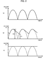
- Fig. 2(a) shows voltage waveforms in which ripples are 100%
- Fig. 2(b) shows voltage waveforms in which ripples are 50%
- Fig. 2(c) shows voltage waveforms in which ripples are 0%.
- the ratio of ripples decreases as the capacity of the smoothing capacitor 11 increases.
- the capacity of the smoothing capacitor 11 is determined based on both this relationship (between the ratio of ripples and the capacity of the smoothing capacitor 11) and the induced voltage.
- pulsation voltage including ripples of 100% is outputted from the smoothing capacitor 11.
- the electric power tool 1 A can improve the power factor without equipping with the power-factor improvement circuit with the smoothing capacitor 11 having small capacity that outputs pulsation voltage having maximum voltage larger than the induced voltage and minimum voltage smaller than the induced voltage to generate the section Y.
- the inverter circuit 8 is controlled not so as to stop operations even in the section Y where the magnitude of pulsation voltage is smaller than the induced voltage.
- This control can prevent energy stored in the stator windings U, V, and W of the motor 5 from flowing reversely toward the smoothing capacitor 11, and the voltage of the smoothing capacitor 11 from increasing rapidly. Hence, damage and deterioration of quality of the smoothing capacitor 11 can be prevented.
- the inverter circuit 8 may be controlled to stop operations if current detected by the motor-current detecting circuit 71 exceeds an overcurrent threshold.
- the above control that does not stop operations of the inverter circuit 8 while the trigger switch 3 is operated can be also used in a construction that does not equip with the smoothing capacitor 11.
- the electric power tool 1B has an identical circuit configuration ( Fig. 1 ) as the electric power tool 1A according to the first embodiment. Therefore, the descriptions of the circuit configuration are omitted.
- the inverter circuit 8 needs to be driven by voltage within a usable range R1 ( Fig. 7 ) (for example, rectified voltage of approximately 110 to 200V, effective value of AC input voltage of approximately 80 to 120V, max (peak) value of AC input voltage of approximately 120 to 140V).
- Fig. 6(a) shows a relationship between current flowing through the motor 5 and the rectified voltage outputted from the rectifier circuit 10 at a normal condition.
- Fig. 6(b) if current flowing through the motor 5 is large, voltage generated from L component in the circuit can be superimposed onto the rectified voltage outputted from the rectifier circuit 10. If this voltage does not fall within the usable range R1 of the inverter circuit 8, the inverter circuit 8 can be damaged.
- the electric power tool 1B of the present embodiment prohibits (restricts) supplying of electric power to the motor 5, if voltage outside a preset range R2 ( Fig. 7 ) that falls into the usable range R1 is supplied to the inverter circuit 8 (the arithmetic section 78).
- a prohibiting range R3 that is less than or equal to a voltage threshold A (for example, 120V), or falls into a prohibiting range R4 is larger than or equal to a voltage threshold B (for example, 140V)
- the PWM duties of PWM signals H4-H6 outputted to the switching elements Q4-Q6 are set to zero, thereby prohibiting supplying of electric power to the motor 5.
- failure of the inverter circuit 8 can be prevented.
- rectified voltage V2 detected by the rectified-voltage detecting circuit 72 is less than or equal to a voltage threshold C (for example, 110V), or is larger than or equal to a voltage threshold D (for example, 200V), supplying of electric power to the motor 5 is prohibited in order to protect the inverter circuit 8.
- a voltage threshold C for example, 110V
- a voltage threshold D for example, 200V
- control voltage V3 detected by the control-circuit-voltage detecting circuit 73 is less than or equal to a voltage threshold E (for example, 10V, not shown), or is larger than or equal to a voltage threshold F (for example, 20V, not shown), supplying of electric power to the motor 5 is prohibited in order to protect the arithmetic section 78.
- a voltage threshold E for example, 10V, not shown
- a voltage threshold F for example, 20V, not shown
- Fig. 8 is a flowchart of the prohibiting control according to the present embodiment. The flowchart is started when a power switch (not shown) of the electric power tool 1B is turned on.
- the arithmetic section 78 determines whether the peak voltage V1 detected by the AC-input-voltage detecting circuit 80 is less than or equal to the voltage threshold A, or is larger than or equal to the voltage threshold B (S101).
- target duty Dt of the PWM signals H4, H5, and H6 is set to 0%, thereby prohibiting supplying of electric power to the motor 5 (S102). This prevents supply of voltage outside the usable range R1 to the inverter circuit 8.
- the arithmetic section 78 determines whether the rectified voltage V2 detected by the rectified-voltage detecting circuit 72 is less than or equal to the voltage threshold C, or is larger than or equal to the voltage threshold D (S103).
- the target duty Dt of the PWM signals H4, H5, and H6 is set to 0%, thereby prohibiting supplying of electric power to the motor 5 (S102). This prevents supply of voltage outside the usable range to the inverter circuit 8.
- the arithmetic section 78 determines whether the control voltage V3 detected by the control-circuit-voltage detecting circuit 73 is less than or equal to the voltage threshold E, or is larger than or equal to the voltage threshold F (S104).
- control voltage V3 is less than or equal to the voltage threshold E, or is larger than or equal to the voltage threshold F (S104: Yes)
- the target duty Dt of the PWM signals H4, H5, and H6 is set to 0%, thereby prohibiting supplying of electric power to the motor 5 (S102). This prevents supply of voltage outside the usable range to the arithmetic section 78.
- control voltage V3 is larger than the voltage threshold E and is less than the voltage threshold F (S104: No)
- the arithmetic section 78 determines whether the trigger switch 3 is turned on (S105).
- the arithmetic section 78 determines whether the peak voltage V1 is larger than or equal to a voltage threshold G (S106).
- the inverter circuit 8 if the peak voltage V1 falls into a prevention range R5 that is smaller than the voltage threshold B and larger than or equal to a voltage threshold G (for example, 105V), the inverter circuit 8 is not damaged at this time.
- a voltage threshold G for example, 105V
- the peak voltage V1 can easily go out of the preset range R2 if current increases or noises are generated.
- the rectified voltage V2 by performing a similar control if the rectified voltage V2 is larger than or equal to a voltage threshold H (for example, 170V) as well, voltage supplied to the inverter circuit 8 and the arithmetic section 78 can be reduced. This can prevent increasing of the rotational speed of the motor increases due to high voltage input, which causes mechanical damages in a mechanical section and a motor section.
- a voltage threshold H for example, 170V
- the arithmetic section 78 sets the target duty Dt to 100% (S108) and returns to S101 because the peak voltage V1 falls into a normal range R6.
- the preset range R2 that falls into the usable range R1 is set, and supplying of electric power to the motor 5 is prohibited if voltage outside the preset range R2 is supplied to the inverter circuit 8 (the arithmetic section 78).
- This can prevent supply of voltage outside the usable range R1 the inverter circuit 8 (the arithmetic section 78), thereby preventing fail of the inverter circuit 8 (the arithmetic section 78).
- the electric power tool 1B of the present embodiment in a state where the motor 5 is driven, if voltage supplied to the inverter circuit 8 (the arithmetic section 78) falls into the preset range R2 but is outside the normal range R6, that is, voltage falls into the prevention range R5, a control for reducing the voltage is performed. This can prevent supply of voltage outside the usable range is supplied to the inverter circuit 8 (the arithmetic section 78).
- DC power from the battery pack 20 may be directly supplied to the inverter circuit 8, as shown in Fig. 11 .
- a battery-voltage detecting circuit (the voltage detecting unit of the present invention) (referred as "BVD" in Fig. 11 ) 81 is provided instead of the rectified-voltage detecting circuit 72 shown in Fig. 1 .
- VBD battery-voltage detecting circuit
- a boost-circuit-voltage supplying circuit (referred as "BVS” in Fig. 11 ) 40 and a boost-circuit-voltage detecting circuit (referred as “BVC” in Fig. 11 ) 82 are provided, instead of the control-circuit-voltage supplying circuit 4 and the control-circuit-voltage detecting circuit 73 shown in Fig. 11 .
- voltage boosted by the boost-circuit-voltage supplying circuit 40 is supplied to the arithmetic section 78.
- voltage detected by the battery-voltage detecting circuit 81 or voltage detected by the boost-circuit-voltage detecting circuit 82 is outside the preset range, supply of electric power to the motor 5 is prohibited.
- prohibition of supplying of electric power to the motor 5 is determined for each voltage at a plurality of locations.
- prohibition of supplying of electric power to the motor 5 may be determined based on a voltage at any one of the plurality of locations.
- the electric power tool 1C has an identical circuit configuration ( Fig. 1 ) as the electric power tool 1A according to the first embodiment. Therefore, the descriptions of the circuit configuration are omitted.
- current flowing through the motor 5 is proportional to load applied to the motor 5.
- the motor 5 can be damaged when great current flows through the motor 5 (great load is applied on the motor 5).
- the electric power tool 1C performs a control for setting a target current It smaller than an overcurrent threshold Ith, and decreasing PWM duties of the PWM signals H4-H6 outputted to the switching elements Q4-Q6 if current detected by the motor-current detecting circuit 71 becomes larger than the target current It.
- current larger than the target current It is prevented from flowing through the motor 5, thereby preventing overcurrent from flowing through the motor 5.
- a smooth operation can be ensured. Further, it becomes possible to protect the inverter circuit 8 vulnerable to overcurrent.
- Fig. 15 is a flowchart of the voltage control according to the third embodiment. This flowchart is started when the trigger switch 3 is turned on.
- the arithmetic section 78 obtains current I flowing through the motor 5 from the motor-current detecting circuit 71 (S201), and determines whether the current I is larger than the overcurrent threshold Ith (S202).
- the arithmetic section 78 sets the target duty Dt of the PWM signals H4-H6 to 0%, thereby stopping supply of electric power to the motor 5 (S203). With this operation, overcurrent is prevented from flowing through the motor 5.
- the arithmetic section 78 determines whether the current I is larger than the target current It (S204).
- the arithmetic section 78 sets (increases) the target duty Dt for increasing the current I to the target current It (S205) and returns to S201.
- the arithmetic section 78 decreases the target duty Dt to decrease the target current It (S205) and returns to S201.
- the target duty Dt is decreased.
- overcurrent can be prevented from flowing through the motor 5.
- a possibility of stop of the motor 5 due to overcurrent is decreased, a smooth operation can be ensured. Further, it becomes possible to protect the inverter circuit 8 vulnerable to overcurrent.
- the target duty Dt is decreased at a constant rate (Da%) if the current I is larger than the target current It.
- the decreasing rate may be changed in accordance with the current I.
- supply of voltage to the motor 5 is stopped if the current I is larger than the overcurrent threshold Ith.
- supply of voltage to the motor 5 may be stopped if the current I is larger than the target current It and is less than or equal to the overcurrent threshold Ith for a preset period or longer. In this case, the period may be changed depending on vulnerability of the motor 5 and the inverter circuit 8 to overcurrent.
- the electric power tool 1D has an identical circuit configuration ( Fig. 1 ) as the electric power tool 1A according to the first embodiment. Therefore, the descriptions of the circuit configuration are omitted.
- the target duty Dt is changed in accordance with the rotational speed of the motor 5. Specifically, the target duty Dt is set to a small value while the rotational speed of the motor 5 is low, so that large voltage is not supplied to the motor 5. With this operation, as shown in Fig. 17 , while the rotational speed of the motor 5 is low, large current can be prevented from flowing through the motor 5. Hence, overcurrent through the motor 5 can be prevented appropriately.
- Fig. 18 is a flowchart of the voltage control according to the present embodiment. This flowchart starts when the trigger switch 3 is turned on. Note that steps S301-S303 are identical to steps S201-S203 in Fig. 15 , and thus descriptions are omitted.
- the arithmetic section 78 obtains rotational speed N of the motor 5 from the motor-rotational-speed detecting circuit 77 (S304). Then, the arithmetic section 78 sets, based on the rotational speed N, the target current It and the target duty Dt for increasing the current I to the target current It (S305), and returns to S301.
- the target duty Dt is increased proportionally to 100% when the rotational speed is 0 rpm to a preset rpm, and is fixed at 100% when the rotational speed is higher than the preset rpm.
- the target duty Dt is changed in accordance with the rotational speed of the motor 5.
- the electric power tool 1D has an identical circuit configuration ( Fig. 1 ) as the electric power tool 1A according to the first embodiment. Therefore, the descriptions of the circuit configuration are omitted.
- the smoothing capacitor 23 having small capacity is used. Especially, when the capacity is less than or equal to 10uF (microfarad), pulsation voltage including ripples can be outputted from the smoothing capacitor 23.
- the target duty Dt is increased immediately after the current I decreases to a value less than equal to the target current It. Therefore, as shown in Fig. 19 , even if the current I is decreases to a value less than or equal to the target current It in one ripple, the current I exceeds the target current It in next ripple again. In other words, current exceeding the target current It flows through the motor 5 at each cycle of AC (alternate current). As the result, the motor 5 can be stopped due to overcurrent, or, at least, unnecessary heat is generated in the motor 5.
- the electric power tool 1E determines whether or not a peak current Ip is larger than the target current It, reduces the target duty Dt when the peak current Ip is larger than the target current It, keeps the decreased duty Dt until a next peak current Ip is detected even if the current I decreases to a value less than or equal to the target current It, and increases the duty Dt stepwise if the peak current Ip is smaller than the target current It. With this operation, current exceeding the target current It is prevented from flowing through the motor 5 at each cycle of AC.
- a capacitor of 0.47uF (microfarad) is used in the present embodiment. If such capacitor is used, large pulsation voltage including large ripples can be generated. For example, if a ripple is larger than or equal to 70%, it can be said that the large pulsation is generated.
- the size of ripple is denoted by (dV/V*) x 100% (V* is a maximum voltage inputted into the electric power tool 1E, and dV is a rate of change of voltage).
- Fig. 21 is a flowchart of the voltage control according to the present embodiment. This flowchart starts when the trigger switch 3 is turned on. Note that steps S401-S403 are identical to steps S201-S203 in Fig. 15 , and thus descriptions are omitted.
- the arithmetic section 78 determines whether the current I(t) is smaller than a previous current I(t-1) (S404).
- the arithmetic section 78 stores the current I(t) as the previous current I(t-1) (S405), and returns to S401.
- the arithmetic section 78 specifies the previous current I(t-1) as the peak current Ip (S406). Note that, in the present embodiment, the current I(t) is detected in a sampling period such that a value sufficiently close to the actual peak current can be detected.
- the arithmetic section 78 determines whether the peak current Ip is larger than the target current It (S407).
- the arithmetic section 78 sets the target duty Dt for increasing the peak current Ip to the target current It (S408), and returns to S401.
- the arithmetic section 78 decreases the target duty Dt to decrease the target current It (S409), and then returns to S401.
- the electric power tool 1E determines whether or not a peak current Ip is larger than the target current It, reduces the target duty Dt when the peak current Ip is larger than the target current It, keeps the decreased duty Dt until a next peak current Ip is detected even if the current I decreases to a value less than or equal to the target current It, and increases the duty Dt stepwise if the peak current Ip is smaller than the target current It. With this operation, current exceeding the target current It is prevented from flowing through the motor 5 at each cycle of AC.
- the electric power tool 1F has an identical circuit configuration ( Fig. 1 ) as the electric power tool 1A according to the first embodiment. Therefore, the descriptions of the circuit configuration are omitted.
- the third embodiment and the fourth embodiment are implemented concurrently. Specifically, the target duty Dt is changed in accordance with the rotational speed of the motor 5, and then, if the current I is larger than the target current It, the target duty Dt is reduced.
- the arithmetic section 78 sets the target duty Dt such that large voltage is not supplied to the motor 5 while the rotational speed of the motor 5 is low, and fixes the duty at 100% after the rotational speed of the motor 5 becomes larger than or equal to a preset value. After the duty is fixed at 100%, the arithmetic section 78 decreases the target duty Dt if the current I becomes larger than the target current It.
- Fig. 23 is a flowchart of the voltage control according to the sixth embodiment. This flowchart starts when the trigger switch 3 is turned on.
- the arithmetic section 78 obtains the current I flowing through the motor 5 from the motor-current detecting circuit 71 (S501), and determines whether the current I is larger than the overcurrent threshold Ith (S502).
- the arithmetic section 78 sets the target duty Dt of the PWM signals H4, H5, and H6 to 0%, thereby stopping supply of electric power to the motor 5 (S503).
- the arithmetic section 78 obtains the rotational speed N of the motor 5 from the motor-rotational-speed detecting circuit 77 (S504) and sets the target current It and the target Dt based on the rotational speed N (S505).
- the arithmetic section 78 determines whether the current I is larger than the target current It set in S505 (S506).
- the arithmetic section 78 increases the target duty Dt (S507), and returns to S501.
- the arithmetic section 78 decreases the target duty Dt (S508), and then returns to S501.
- the target duty Dt is decreased at a constant decreasing rate (Da%) if the current I is larger than the target current It.
- the decreasing rate may be changed in accordance with the current I.
- supply of voltage to the motor 5 is stopped if the current I is larger than the overcurrent threshold Ith.
- supply of voltage to the motor 5 may be stopped if the current I is larger than the target current It and is less than or equal to the overcurrent threshold Ith for a preset period or longer. In this case, the preset period may be changed depending on vulnerability of the motor 5 and the inverter circuit 8 to overcurrent.
- a lock detection may be performed at the end of a driving operation.
- the lock detection could be performed (1) if the rotational speed N is less than or equal to a preset value, (2) if the rotational speed N is less than or equal to a preset value, and the current I is larger than or equal to a preset value, or (3) if the current I continues being larger than or equal to a preset value for a preset period or longer.
- any two or more of the electric power tools 1A-1F can be arbitrarily combined with one another.
- An electric power tool comprising:
- control unit prevents the inverter circuit from performing the switching operations when a current flowing through the brushless motor is larger than an overcurrent threshold.
- An electric power tool comprising:
- An electric power tool comprising:
- control unit controls the voltage supplying unit to stop supplying the drive voltage when the current detected by the current detecting circuit is larger than a second current larger than the first current.
- the voltage supplying unit supplies a pulsation voltage including a plurality of ripples as the drive voltage to the motor; wherein the current detecting circuit detects a peak of the current flowing through the motor; and wherein the control unit controls the voltage supplying unit to decrease the drive voltage when the peak detected by the current detecting circuit is larger than the first current, keep the decreased drive voltage until a next peak is detected, and increases the decreased drive voltage stepwise if the next peak is smaller than the first current.
- the electric power tool according to aspect 5, wherein the voltage supplying unit includes an inverter circuit.
- An electric power tool comprising:
- An electric power tool comprising:
- control unit gradually decreases the drive voltage when the current detected by the current detecting circuit is larger than the preset current value.
- control unit performs a PWM control to decrease the drive voltage, wherein the control unit performs the PWM control with a duty smaller than 100% when the current detected by the current detecting circuit is larger than the preset current value, and wherein the control unit performs the PWM control with a duty of 100% when the current detected by the current detecting circuit is smaller than the preset current value.
- An electric power tool comprising:
- the electric power tool according to aspect 13, wherein the restraining unit performs a PWM control to retrain a peak of the pulsation current flowing through the brushless motor.
- An electric power tool comprising:
- An electric power tool comprising:
- the electric power tool wherein the voltage detecting circuit detects a peak of the rectified voltage, and wherein the control unit prohibits the voltage supplying unit from supplying the drive voltage to the motor when the rectified voltage detected by the voltage detecting circuit is outside the preset range.
- An electric power tool comprising:
- An electric power tool comprising:
- An electric power tool comprising:
Abstract
Description
- The invention relates to an electric power tool.
- Japanese Patent Publication No.
4487836 - Because the above conventional electric power tool includes a smoothing capacitor having large capacity, power factor of AC power is deteriorated.
- Further, in order to improve the power factor, an electric power tool equipping with a power-factor improvement circuit can be also conceived. However, such configuration increases the size of the electric power tool and increases the cost.
- In view of the foregoing, it is an object of the invention to provide an electric power tool capable of improving power factor without equipping with a power-factor improvement.
- In order to attain the above and other objects, the invention provides an electric power tool including: a brushless motor having a plurality of stator windings and configured to rotate in accordance with voltages applied to the plurality of stator windings, an induced voltage being generated in accordance with a rotation of the brushless motor; a rectifier circuit configured to rectify an AC voltage; a smoothing capacitor configured to smooth the AC voltage rectified by the rectifier circuit to a pulsation voltage having a maximum value larger than the induced voltage and a minimum value smaller than the induced voltage; and an inverter circuit configured to perform switching operations to output the pulsation voltage to the plurality of stator windings by rotation.
- It is preferable that the electric power tool further includes: a receiving unit configured to receive an instruction for the inverter circuit to perform the switching operations; and a control unit configured to control the inverter circuit to continue to perform the switching operations while the receiving unit is receiving the instruction, even if the pulsation voltage is smaller than the induced voltage.
- It is preferable that the control unit prevents the inverter circuit from performing the switching operations when a current flowing through the brushless motor is larger than an overcurrent threshold.
- Another aspect of the present invention provides an electric power tool including: a brushless motor including: a stator having a plurality of stator windings to which an AC voltage is applied from an AC power source; and a rotor rotatable for the stator; an end tool that is driven in accordance with the rotation of the rotor; an inverter circuit configured to perform switching operations to output the pulsation voltage to the plurality of stator windings by rotation, even if the AC voltage is smaller than a preset voltage.
- Another aspect of the present invention provides an electric power tool including: a motor; a voltage supplying unit configured to supply a drive voltage to the motor; a current detecting circuit configured to detect a current flowing through the motor; and a control unit configured to control the voltage supplying unit to decrease the drive voltage when the current detected by the current detecting circuit is larger than a first current.
- It is preferable that the control unit controls the voltage supplying unit to stop supplying the drive voltage when the current detected by the current detecting circuit is larger than a second current larger than the first current.
- It is preferable that the voltage supplying unit supplies a pulsation voltage including a plurality of ripples as the drive voltage to the motor. The current detecting circuit detects a peak of the current flowing through the motor. The control unit controls the voltage supplying unit to decrease the drive voltage when the peak detected by the current detecting circuit is larger than the first current, keep the decreased drive voltage until a next peak is detected, and increases the decreased drive voltage stepwise if the next peak is smaller than the first current.
- It is preferable that the voltage supplying unit includes an inverter circuit.
- Another aspect of the present invention provides an electric power tool including: a motor; a voltage supplying unit configured to supply a drive voltage set to a target voltage to the motor; a rotational speed detecting circuit configured to detect a rotational speed of the motor; and a control unit configure to change the target voltage based on the rotational speed detected by the rotational speed detecting unit.
- Another aspect of the present invention provides an electric power tool including: a power cable connectable to an AC power source; a brushless motor that is rotated with a power supplied from the AC power source; an end tool that is driven in accordance with the rotation of the brushless motor; a current detecting circuit configured to detect a current flowing through the brushless motor; and a control unit configured to decrease a drive voltage of the brushless motor when the current detected by the current detecting circuit is larger than a preset current value.
- It is preferable that the control unit gradually decreases the drive voltage when the current detected by the current detecting circuit is larger than the preset current value.
- It is preferable that the control unit performs a PWM control to decrease the drive voltage. The control unit performs the PWM control with a duty smaller than 100% when the current detected by the current detecting circuit is larger than the preset current value. The control unit performs the PWM control with a duty of 100% when the current detected by the current detecting circuit is smaller than the preset current value.
- Another aspect of the present invention provides an electric power tool including: a power cable connectable to an AC power source; a brushless motor that is rotated with an AC power supplied from the AC power source, a pulsation current flowing through the brushless motor with the AC power; an end tool that is driven in accordance with the rotation of the brushless motor; a current detecting circuit configured to detect the pulsation current flowing through the brushless motor; and a restraining unit configured to retrain a peak of the pulsation current flowing through the brushless motor.
- It is preferable that the restraining unit performs a PWM control to retrain a peak of the pulsation current flowing through the brushless motor.
- Another aspect of the present invention provides an electric power tool including: a motor; a voltage supplying unit configured to generate a drive voltage from a DC voltage and supply the drive voltage to the motor; a voltage detecting circuit configured to detect the DC voltage; and a control unit configured to prohibit the voltage supplying unit from supplying the drive voltage to the motor when the DC voltage detected by the voltage detecting circuit is outside a preset range.
- Another aspect of the present invention provides an electric power tool including: a motor; a rectifier circuit configured to convert an AC voltage into a rectified voltage; a voltage supplying unit configured to generate a drive voltage from the rectified voltage and supply the drive voltage to the motor; a voltage detecting circuit configured to detect the rectified voltage; and a control unit configured to prohibit the voltage supplying unit from supplying the drive voltage to the motor when the rectified voltage detected by the voltage detecting circuit is outside a preset range.
- It is preferable that the voltage detecting circuit detects a peak of the rectified voltage. The control unit prohibits the voltage supplying unit from supplying the drive voltage to the motor when the rectified voltage detected by the voltage detecting circuit is outside the preset range.
- Another aspect of the present invention provides an electric power tool including: a power cable connectable to an AC power source; a voltage supplying unit configured to generate a drive voltage from the power supplied from the AC power source; a brushless motor that is rotated with the drive voltage; an end tool that is driven in accordance with the rotation of the brushless motor; a current detecting circuit configured to detect a current flowing through the brushless motor; and a control unit configured to perform a PWM control to control the voltage supplying unit. The control unit determines a duty of the PWM control based on a difference between the current detected by the current detecting circuit and a first current value when the current detected by the current detecting circuit is larger than the first current value.
- Another aspect of the present invention provides an electric power tool including: a power cable connectable to an AC power source; a voltage supplying unit configured to generate a drive voltage from the power supplied from the AC power source; a brushless motor that is rotated with the drive voltage; an end tool that is driven in accordance with the rotation of the brushless motor; a current detecting circuit configured to detect a current flowing through the brushless motor; and a control unit configured to perform a PWM control to control the voltage supplying unit. The control unit decreases a duty of the PWM control when the drive voltage is larger than a first voltage value.
- Another aspect of the present invention provides an electric power tool including: a power cable connectable to an AC power source; a voltage supplying unit configured to generate a drive voltage from the power supplied from the AC power source; a brushless motor that is rotated with the drive voltage; an end tool that is driven in accordance with the rotation of the brushless motor; a voltage detecting circuit configured to detect the drive voltage; and a control unit configured to perform a PWM control to control the voltage supplying unit. The control unit determines a duty of the PWM control based on a difference between the voltage detected by the voltage detecting circuit and a first voltage value when the voltage detected by the voltage circuit is larger than the first voltage value.
-
- [
Fig. 1] Fig. 1 is a circuit diagram of an electric power tool according to a first embodiment of the present invention. - [
Fig. 2] Fig. 2 is an explanation diagram of pulsation voltages including ripples. - [
Fig. 3] Fig. 3 is a diagram showing change of current when a smoothing capacitor having small capacitor is used. - [
Fig. 4] Fig. 4 is a diagram showing current paths for operations of an inverter circuit according to the first embodiment of the present invention. - [
Fig. 5] Fig. 5 is a diagram showing change of current when the inverter circuit is stopped. - [
Fig. 6] Fig. 6 is a diagram showing a relationship between current flowing through a motor and rectified voltage. - [
Fig. 7] Fig. 7 is a diagram showing thresholds for peak voltage of AC voltage. - [
Fig. 8] Fig. 8 is a flowchart of a prohibiting control according to a second embodiment of the present invention. - [
Fig. 9] Fig. 9 is a diagram showing a relationship between voltage and target duty. - [
Fig. 10] Fig. 10 is a diagram showing a control according to the second embodiment of the present invention. - [
Fig.11] Fig. 11 is a circuit diagram of an electric power tool according to a first modification of the second embodiment of the present invention. - [
Fig. 12] Fig. 12 is a circuit diagram of an electric power tool according to a second modification of the second embodiment of the present invention. - [
Fig. 13] Fig. 13 is a diagram showing a relationship between load and current. - [
Fig. 14] Fig. 14 is a diagram showing a control according to a third embodiment of the present invention. - [
Fig. 15] Fig. 15 is a flowchart of the control according to the third embodiment of the present invention. - [
Fig. 16] Fig. 16 is a diagram showing a relationship between a target duty and a rotational speed when a control according to a fourth embodiment of a present invention is performed. - [
Fig. 17] Fig. 17 is a diagram showing the control according to the fourth embodiment of the present invention. - [
Fig. 18] Fig. 18 is a flowchart of the control according to the fourth embodiment of the present invention. - [
Fig. 19] Fig. 19 is a diagram showing waveform of current when a control according to the third embodiment is performed for AC power. - [
Fig. 20] Fig. 20 is a diagram showing a control according to a fifth embodiment of the present invention. - [
Fig. 21] Fig. 21 is a flowchart of the control according to the fifth embodiment of the present invention. - [
Fig. 22] Fig. 22 is a diagram showing a control according to a sixth embodiment of the present invention. - [
Fig. 23] Fig. 23 is a flowchart of the control according to the sixth embodiment of the present invention. -
- 1A-1E Electric Power Tool
- 5 Motor
- 8 Inverter Circuit
- 10 Rectifier Circuit
- 11 Smoothing Capacitor
- Hereinafter, an
electric power tool 1A according to a first embodiment of the invention will be described while referring toFigs. 1 through 5 . -
Fig. 1 is a circuit diagram of theelectric power tool 1A according to the first embodiment. As shown inFig. 1 , thepower tool 1 includes a trigger switch (the receiving unit of the present invention) 3, a control-circuit-voltage supplying circuit (referred as "CVS" inFig. 1 ) 4, amotor 5, rotor-position detecting elements 6, acontroller 7, an inverter circuit (the inverter circuit and the voltage supplying unit of the present invention) 8, a normal-mode filter 9, arectifier circuit 10, and a smoothing capacitor 11. - When the
trigger switch 3 is operated, AC voltage outputted from acommercial power source 2 is rectified and smoothed by therectifier circuit 10 and the smoothing capacitor 11, and is supplied to themotor 5 via theinverter circuit 8. Further, when thetrigger switch 3 is operated, the control-circuit-voltage supplying circuit 4 generates a control-circuit driving voltage (15V in the present embodiment) and supplies the control-circuit driving voltage to thecontroller 7. - The
motor 5 is a three-phase brushless DC motor, and includes arotor 5A and astator 5B. Therotor 5A is made of a permanent magnet including a plurality of sets (two sets in the present embodiment) of N poles and S poles. Thestator 5B is made of three-phase stator windings U, V, and W that are connected by star connection. The motor 5 (therotor 5A) rotates by sequentially switching the stator windings U, V, and W through which current flows. Switching of the stator windings U, V, and W will be described later. - The rotor-
position detecting elements 6 are arranged at positions confronting the permanent magnet of therotor 5A with a predetermined interval (for example, an angle of 60 degrees) in the circumferential direction of therotor 5A. The rotor-position detecting elements 6 output a signal in accordance with rotational position of the rotor 6A. - The
controller 7 includes a motor-current detecting circuit (the current detecting unit of the present invention) (referred as "MCD" inFig. 1 ) 71, a rectified-voltage detecting circuit (the voltage detecting unit of the present invention) (referred as "RVD" inFig. 1 ) 72, a control-circuit-voltage detecting circuit (referred as "CVD" inFig. 1 ) 73, a switch-operation detecting circuit (referred as "SOD" inFig. 1 ) 74, an applied-voltage setting circuit (referred as "AVS" inFig. 1 ) 75, a rotor-position detecting circuit (referred as "RPD" inFig. 1 ) 76, a motor-rotational-speed detecting circuit (the rotational speed detecting unit of the present invention) (referred as "RSD" inFig. 1 ) 77, an arithmetic section (the control unit of the present invention) 78, a control-signal outputting circuit (referred as "CSO" inFig. 1 ) 79, and an AC-input-voltage detecting circuit (referred as "AVD" inFig. 1 ) 80. - The AC-input-
voltage detecting circuit 80 detects a peak value of AC voltage outputted from thecommercial power source 2, and outputs the peak value to thearithmetic section 78. In the present embodiment, AC voltage is detected in a sampling period that a value sufficiently close to the actual peak value can be detected. - The motor-
current detecting circuit 71 detects current supplied to themotor 5, and outputs the current to thearithmetic section 78. The rectified-voltage detecting circuit 72 detects voltage outputted from therectifier circuit 10 and the smoothing capacitor 11, and outputs the voltage to thearithmetic section 78. The control-circuit-voltage detecting circuit 73 detects control-circuit driving voltage supplied from the control-circuit-voltage supplying circuit 4, and outputs the driving voltage to thearithmetic section 78. The switch-operation detecting circuit 74 detects whether thetrigger switch 3 is operated, and outputs the detection result to thearithmetic section 78. The applied-voltage setting circuit 75 detects operation amount of thetrigger switch 3, and outputs the operation amount to thearithmetic section 78. - The rotor-
position detecting circuit 76 detects rotational position of the rotor 6A based on signals from the rotor-position detecting elements 6, and outputs the rotational position to the motor-rotational-speed detecting circuit 77 and thearithmetic section 78. The motor-rotational-speed detecting circuit 77 detects rotational speed of the rotor 6A based on signals from the rotor-position detecting circuit 76, and outputs the rotational speed to thearithmetic section 78. - The
arithmetic section 78 generates switching signals H1-H6 based on signals from the rotor-position detecting circuit 76 and from the motor-rotational-speed detecting circuit 77, and outputs the switching signals H1-H6 to the control-signal outputting circuit 79. Further, thearithmetic section 78 adjusts switching signals H4-H6 as pulse width modulation signal (PWM signal) based on signals from the applied-voltage setting circuit 75, and outputs the PWM signal to the control-signal outputting circuit 79. The switching signals H1-H6 are outputted to theinverter circuit 8 via the control-signal outputting circuit 79. Note that thecontroller 7 may be so configured to adjust the switching signals H1-H3 as PWM signals. - The
inverter circuit 8 includes switching elements Q1-Q6. Each gate of the switching elements Q1-Q6 is connected with the control-signal outputting circuit 79, and each drain or source of the switching elements Q1-Q6 is connected with the stator windings U, V, and W of thestator 5B. - The switching elements Q1-Q6 performs switching operations based on the switching signals H1-H6 inputted from the control-
signal outputting circuit 79, changes DC voltage of thebattery pack 20 applied to theinverter circuit 8 into three-phase (U-phase, V-phase, and W-phase) voltages Vu, Vv, and Vw, and supplies the three-phase voltages Vu, Vv, and Vw to the stator windings U, V, and W, respectively. - Specifically, the switching signals H1-H6 are inputted to the switching elements Q1-Q6, respectively. With this operation, the energized stator windings U, V, and W, that is, the rotational direction of the
rotor 5A is controlled. At this time, amount of electric power supplied to the stator windings U, V, and W is controlled with the switching signals H4-H6 which are also PWM signals. - With the above-described configuration, the
electric power tool 1A can supply themotor 5 with driving voltage in accordance with the operation amount of thetrigger switch 3. - Here, because a conventional electric power tool includes a smoothing capacitor having large capacity, power factor of AC power is deteriorated. Further, in order to improve the power factor, a configuration equipping with a power-factor improvement circuit can be also conceived. However, such configuration increases the size of the power tool and increases the cost.
- On the other hands, a smoothing capacitor having small capacity cannot completely smooth AC voltage outputted from the
rectifier circuit 10. As the result, pulsation voltage including ripples (for example,Fig. 2(b) ) is outputted from the smoothing capacitor. - When the
motor 5 is rotated, induced voltage is generated in themotor 5. In order to themotor 5, it is required to apply voltage larger than the induced voltage to themotor 5. Thus, if the pulsation voltage is applied to themotor 5, themotor 5 cannot be driven in a section Y (Fig. 3 ) where the magnitude of the pulsation voltage is smaller than the induced voltage. That is, as shown inFig. 4(a) , current flows in theelectric power tool 1A in a section X where the magnitude of the pulsation voltage is larger than or equal to the induced voltage. In contrast, as shown inFig. 4(b) , current does not flow in theelectric power tool 1A in the section Y where the magnitude of the pulsation voltage is smaller than the induced voltage. - However, the
electric power tool 1A according to the present embodiment uses the smoothing capacitor 11 having small capacity, by design, that outputs pulsation voltage having maximum voltage larger than the induced voltage and minimum voltage smaller than the induced voltage to generate the section Y. Hereinafter, the reason why theelectric power tool 1A according to the present embodiment uses the smoothing capacitor 11 having small capacity will be described. -
Fig. 2(a) shows voltage waveforms in which ripples are 100%,Fig. 2(b) shows voltage waveforms in which ripples are 50%, andFig. 2(c) shows voltage waveforms in which ripples are 0%. As shown inFig. 2 , the ratio of ripples decreases as the capacity of the smoothing capacitor 11 increases. In the present embodiment, the capacity of the smoothing capacitor 11 is determined based on both this relationship (between the ratio of ripples and the capacity of the smoothing capacitor 11) and the induced voltage. Hereinafter, a case will be described in which pulsation voltage including ripples of 100% is outputted from the smoothing capacitor 11. - As described above, current does not flow in the
electric power tool 1A in the section Y. However, if themotor 5 is once driven in the section X, themotor 5 can continue rotating in the section Y due to inertia. Therefore, if themotor 5 is cyclically driven in the section X, themotor 5 can continue rotating even if not driven in the section Y. Hence, theelectric power tool 1 A according to the present embodiment can improve the power factor without equipping with the power-factor improvement circuit with the smoothing capacitor 11 having small capacity that outputs pulsation voltage having maximum voltage larger than the induced voltage and minimum voltage smaller than the induced voltage to generate the section Y. - Further, for saving energy, a control that stops operations of the
inverter circuit 8 in the section Y where the magnitude of pulsation voltage is smaller than the induced voltage is conceivable. - However, if the
inverter circuit 8 is stopped in the section Y, energy stored in the stator windings U, V, and W of themotor 5 flows reversely toward the smoothing capacitor 11 (Fig. 4(c) ) in a section Z (Fig. 5 ) that is immediately after theinverter circuit 8 is stopped. As a result, voltage of the smoothing capacitor 11 increases rapidly, which can cause damage and deterioration of quality of the smoothing capacitor 11. - Hence, in the present embodiment, while the
trigger switch 3 is operated, theinverter circuit 8 is controlled not so as to stop operations even in the section Y where the magnitude of pulsation voltage is smaller than the induced voltage. This control can prevent energy stored in the stator windings U, V, and W of themotor 5 from flowing reversely toward the smoothing capacitor 11, and the voltage of the smoothing capacitor 11 from increasing rapidly. Hence, damage and deterioration of quality of the smoothing capacitor 11 can be prevented. - However, the
inverter circuit 8 may be controlled to stop operations if current detected by the motor-current detecting circuit 71 exceeds an overcurrent threshold. - Further, the above control that does not stop operations of the
inverter circuit 8 while thetrigger switch 3 is operated can be also used in a construction that does not equip with the smoothing capacitor 11. - Next, an
electric power tool 1 B according to a second embodiment of the invention will be described while referring toFigs. 6 through 10 . Theelectric power tool 1B has an identical circuit configuration (Fig. 1 ) as theelectric power tool 1A according to the first embodiment. Therefore, the descriptions of the circuit configuration are omitted. - The
inverter circuit 8 needs to be driven by voltage within a usable range R1 (Fig. 7 ) (for example, rectified voltage of approximately 110 to 200V, effective value of AC input voltage of approximately 80 to 120V, max (peak) value of AC input voltage of approximately 120 to 140V).Fig. 6(a) shows a relationship between current flowing through themotor 5 and the rectified voltage outputted from therectifier circuit 10 at a normal condition. However, as shown inFig. 6(b) , if current flowing through themotor 5 is large, voltage generated from L component in the circuit can be superimposed onto the rectified voltage outputted from therectifier circuit 10. If this voltage does not fall within the usable range R1 of theinverter circuit 8, theinverter circuit 8 can be damaged. - Thus, the
electric power tool 1B of the present embodiment prohibits (restricts) supplying of electric power to themotor 5, if voltage outside a preset range R2 (Fig. 7 ) that falls into the usable range R1 is supplied to the inverter circuit 8 (the arithmetic section 78). - For example, as shown in
Fig. 7 , if peak voltage V1 detected by the AC-input-voltage detecting circuit 80 falls into a prohibiting range R3 that is less than or equal to a voltage threshold A (for example, 120V), or falls into a prohibiting range R4 is larger than or equal to a voltage threshold B (for example, 140V), the PWM duties of PWM signals H4-H6 outputted to the switching elements Q4-Q6 are set to zero, thereby prohibiting supplying of electric power to themotor 5. Thus, failure of theinverter circuit 8 can be prevented. - Additionally, in the present embodiment, although not shown in figures, if rectified voltage V2 detected by the rectified-
voltage detecting circuit 72 is less than or equal to a voltage threshold C (for example, 110V), or is larger than or equal to a voltage threshold D (for example, 200V), supplying of electric power to themotor 5 is prohibited in order to protect theinverter circuit 8. - Further, in the present embodiment, although not shown in figures, if control voltage V3 detected by the control-circuit-
voltage detecting circuit 73 is less than or equal to a voltage threshold E (for example, 10V, not shown), or is larger than or equal to a voltage threshold F (for example, 20V, not shown), supplying of electric power to themotor 5 is prohibited in order to protect thearithmetic section 78. - Here, the above-mentioned prohibiting control performed by the
arithmetic section 78 will be described in detail while referring toFig. 8. Fig. 8 is a flowchart of the prohibiting control according to the present embodiment. The flowchart is started when a power switch (not shown) of theelectric power tool 1B is turned on. - First, the
arithmetic section 78 determines whether the peak voltage V1 detected by the AC-input-voltage detecting circuit 80 is less than or equal to the voltage threshold A, or is larger than or equal to the voltage threshold B (S101). - If the peak voltage V1 is less than or equal to the voltage threshold A, or is larger than or equal to the voltage threshold B (S101: Yes), target duty Dt of the PWM signals H4, H5, and H6 is set to 0%, thereby prohibiting supplying of electric power to the motor 5 (S102). This prevents supply of voltage outside the usable range R1 to the
inverter circuit 8. - On the other hand, if the peak voltage V1 is larger than the voltage threshold A and is less than the voltage threshold B (S101: No), the
arithmetic section 78 then determines whether the rectified voltage V2 detected by the rectified-voltage detecting circuit 72 is less than or equal to the voltage threshold C, or is larger than or equal to the voltage threshold D (S103). - If the rectified voltage V2 is less than or equal to the voltage threshold C, or is larger than or equal to the voltage threshold D (S103: Yes), the target duty Dt of the PWM signals H4, H5, and H6 is set to 0%, thereby prohibiting supplying of electric power to the motor 5 (S102). This prevents supply of voltage outside the usable range to the
inverter circuit 8. - On the other hand, if the rectified voltage V2 is larger than the voltage threshold C and is less than the voltage threshold D (S103: No), the
arithmetic section 78 then determines whether the control voltage V3 detected by the control-circuit-voltage detecting circuit 73 is less than or equal to the voltage threshold E, or is larger than or equal to the voltage threshold F (S104). - If the control voltage V3 is less than or equal to the voltage threshold E, or is larger than or equal to the voltage threshold F (S104: Yes), the target duty Dt of the PWM signals H4, H5, and H6 is set to 0%, thereby prohibiting supplying of electric power to the motor 5 (S102). This prevents supply of voltage outside the usable range to the
arithmetic section 78. - If the control voltage V3 is larger than the voltage threshold E and is less than the voltage threshold F (S104: No), the
arithmetic section 78 then determines whether thetrigger switch 3 is turned on (S105). - If the
trigger switch 3 is not turned on (S105: No), thearithmetic section 78 returns to S101. If thetrigger switch 3 is turned on (S105: Yes), thearithmetic section 78 then determines whether the peak voltage V1 is larger than or equal to a voltage threshold G (S106). - Here, as shown in
Fig. 7 , if the peak voltage V1 falls into a prevention range R5 that is smaller than the voltage threshold B and larger than or equal to a voltage threshold G (for example, 105V), theinverter circuit 8 is not damaged at this time. However, in this range R5, the peak voltage V1 can easily go out of the preset range R2 if current increases or noises are generated. - Accordingly, in the present embodiment, if the peak voltage V1 is larger than or equal to the voltage threshold G (S106: Yes), the
arithmetic section 78 sets the target duty Dt to a value less than 100% (S107) and returns to S101. Specifically, as shown inFig. 9 , thearithmetic section 78 sets the target duty Dt to a value indicated by Dt = (V1/G) x 100, and returns to S101. With this operation, as shown inFig. 10 , if the peak voltage V1 is larger than or equal to the voltage threshold G, voltage supplied to theinverter circuit 8 and thearithmetic section 78 can be reduced. - Further, generally, if current increases, voltage also increases due to the effect of L component of the circuit. However, by decreasing the duty as described above, current is also decreased. Therefore, rise of rectified voltage can be also prevented.
- As to the rectified voltage V2, by performing a similar control if the rectified voltage V2 is larger than or equal to a voltage threshold H (for example, 170V) as well, voltage supplied to the
inverter circuit 8 and thearithmetic section 78 can be reduced. This can prevent increasing of the rotational speed of the motor increases due to high voltage input, which causes mechanical damages in a mechanical section and a motor section. - On the other hand, if the peak voltage V1 is less than the voltage threshold G (S106: No), the
arithmetic section 78 sets the target duty Dt to 100% (S108) and returns to S101 because the peak voltage V1 falls into a normal range R6. - In this way, in the
electric power tool 1B of the present embodiment, the preset range R2 that falls into the usable range R1 is set, and supplying of electric power to themotor 5 is prohibited if voltage outside the preset range R2 is supplied to the inverter circuit 8 (the arithmetic section 78). This can prevent supply of voltage outside the usable range R1 the inverter circuit 8 (the arithmetic section 78), thereby preventing fail of the inverter circuit 8 (the arithmetic section 78). - Further, in the
electric power tool 1B of the present embodiment, in a state where themotor 5 is driven, if voltage supplied to the inverter circuit 8 (the arithmetic section 78) falls into the preset range R2 but is outside the normal range R6, that is, voltage falls into the prevention range R5, a control for reducing the voltage is performed. This can prevent supply of voltage outside the usable range is supplied to the inverter circuit 8 (the arithmetic section 78). - Note that although, in the above-described embodiment, AC power from the
commercial power source 2 is converted into DC power, and then is supplied to theinverter circuit 8, DC power from thebattery pack 20 may be directly supplied to theinverter circuit 8, as shown inFig. 11 . In this case, a battery-voltage detecting circuit (the voltage detecting unit of the present invention) (referred as "BVD" inFig. 11 ) 81 is provided instead of the rectified-voltage detecting circuit 72 shown inFig. 1 . And, if voltage detected by the battery-voltage detecting circuit 81 or voltage detected by the control-circuit-voltage detecting circuit 73 is outside the preset range, supply of electric power to themotor 5 is prohibited. - Further, in order to boost the voltage of the
battery pack 20, as shown inFig. 12 , a configuration is conceivable that a boost-circuit-voltage supplying circuit (referred as "BVS" inFig. 11 ) 40 and a boost-circuit-voltage detecting circuit (referred as "BVC" inFig. 11 ) 82 are provided, instead of the control-circuit-voltage supplying circuit 4 and the control-circuit-voltage detecting circuit 73 shown inFig. 11 . In this configuration, voltage boosted by the boost-circuit-voltage supplying circuit 40 is supplied to thearithmetic section 78. In this configuration, if voltage detected by the battery-voltage detecting circuit 81 or voltage detected by the boost-circuit-voltage detecting circuit 82 is outside the preset range, supply of electric power to themotor 5 is prohibited. - Further, although in the above embodiment, prohibition of supplying of electric power to the
motor 5 is determined for each voltage at a plurality of locations. However, prohibition of supplying of electric power to themotor 5 may be determined based on a voltage at any one of the plurality of locations. - Next, an electric power tool 1C according to a third embodiment of the invention will be described while referring to
Figs. 13 through 15 . The electric power tool 1C has an identical circuit configuration (Fig. 1 ) as theelectric power tool 1A according to the first embodiment. Therefore, the descriptions of the circuit configuration are omitted. - As shown in
Fig. 13 , current flowing through themotor 5 is proportional to load applied to themotor 5. Themotor 5 can be damaged when great current flows through the motor 5 (great load is applied on the motor 5). - Thus, as shown in
Fig. 14 , the electric power tool 1C according to the third embodiment performs a control for setting a target current It smaller than an overcurrent threshold Ith, and decreasing PWM duties of the PWM signals H4-H6 outputted to the switching elements Q4-Q6 if current detected by the motor-current detecting circuit 71 becomes larger than the target current It. With this construction, current larger than the target current It is prevented from flowing through themotor 5, thereby preventing overcurrent from flowing through themotor 5. Further, because a possibility of stop of themotor 5 due to overcurrent decreases, a smooth operation can be ensured. Further, it becomes possible to protect theinverter circuit 8 vulnerable to overcurrent. - Here, the above-mentioned control performed by the
arithmetic section 78 will be described in detail while referring toFig. 15. Fig. 15 is a flowchart of the voltage control according to the third embodiment. This flowchart is started when thetrigger switch 3 is turned on. - First, the
arithmetic section 78 obtains current I flowing through themotor 5 from the motor-current detecting circuit 71 (S201), and determines whether the current I is larger than the overcurrent threshold Ith (S202). - If the current I is larger than the overcurrent threshold Ith (S202: Yes), the
arithmetic section 78 sets the target duty Dt of the PWM signals H4-H6 to 0%, thereby stopping supply of electric power to the motor 5 (S203). With this operation, overcurrent is prevented from flowing through themotor 5. - On the other hand, if the current I is less than or equal to the overcurrent threshold Ith (S202: No), the
arithmetic section 78 then determines whether the current I is larger than the target current It (S204). - If the current I is less than or equal to the target current It (S204: No), the
arithmetic section 78 sets (increases) the target duty Dt for increasing the current I to the target current It (S205) and returns to S201. - Specifically, the
arithmetic section 78 set the target duty Dt based on the following Equation (1): Dt = (It - I) x P + D (P is a feedback gain, and D is a current duty), and increases the duty by Da% toward the target duty Dt. By increasing the duty by Da% in this way, an excessive inrush current can be prevented from flowing through themotor 5. - On the other hand, if the current I is larger than the target current It (S204: Yes), the
arithmetic section 78 decreases the target duty Dt to decrease the target current It (S205) and returns to S201. - In this way, in the electric power tool 1C according to the third embodiment, if the current I flowing through the
motor 5 is larger than the target current It, the target duty Dt is decreased. Thus, because current flowing through themotor 5 is smaller than the target current It, overcurrent can be prevented from flowing through themotor 5. Further, because a possibility of stop of themotor 5 due to overcurrent is decreased, a smooth operation can be ensured. Further, it becomes possible to protect theinverter circuit 8 vulnerable to overcurrent. - Note that, in the above embodiment, the target duty Dt is decreased at a constant rate (Da%) if the current I is larger than the target current It. However, the decreasing rate may be changed in accordance with the current I.
- Further, in the above embodiment, supply of voltage to the
motor 5 is stopped if the current I is larger than the overcurrent threshold Ith. However, supply of voltage to themotor 5 may be stopped if the current I is larger than the target current It and is less than or equal to the overcurrent threshold Ith for a preset period or longer. In this case, the period may be changed depending on vulnerability of themotor 5 and theinverter circuit 8 to overcurrent. - Next, an electric power tool 1D according to a fourth embodiment of the invention will be described while referring to
Figs. 16 through 18 . The electric power tool 1D has an identical circuit configuration (Fig. 1 ) as theelectric power tool 1A according to the first embodiment. Therefore, the descriptions of the circuit configuration are omitted. - If the same voltage is supplied to the
motor 5 in a case where the rotational speed of themotor 5 is low and in a case where the rotational speed of themotor 5 is high, larger current flows through themotor 5 in the case where the rotational speed is low. On the other hand, change in the target duty Dt takes some time to be reflected in a current value. Accordingly, when the rotational speed of themotor 5 is low, even if the control according to the third embodiment is performed, there is a possibility that the control cannot follow and overcurrent flows through themotor 5. - Hence, in the present embodiment, as shown in
Fig. 16 , the target duty Dt is changed in accordance with the rotational speed of themotor 5. Specifically, the target duty Dt is set to a small value while the rotational speed of themotor 5 is low, so that large voltage is not supplied to themotor 5. With this operation, as shown inFig. 17 , while the rotational speed of themotor 5 is low, large current can be prevented from flowing through themotor 5. Hence, overcurrent through themotor 5 can be prevented appropriately. - Next, a control according to the present embodiment will be described while referring to
Fig. 18. Fig. 18 is a flowchart of the voltage control according to the present embodiment. This flowchart starts when thetrigger switch 3 is turned on. Note that steps S301-S303 are identical to steps S201-S203 inFig. 15 , and thus descriptions are omitted. - If the current I is less than or equal to the overcurrent threshold Ith (S302: No), the
arithmetic section 78 obtains rotational speed N of themotor 5 from the motor-rotational-speed detecting circuit 77 (S304). Then, thearithmetic section 78 sets, based on the rotational speed N, the target current It and the target duty Dt for increasing the current I to the target current It (S305), and returns to S301. In the present embodiment, as shown inFig. 16 , the target duty Dt is increased proportionally to 100% when the rotational speed is 0 rpm to a preset rpm, and is fixed at 100% when the rotational speed is higher than the preset rpm. - In this way, in the electric power tool 1 D according to the fourth embodiment, the target duty Dt is changed in accordance with the rotational speed of the
motor 5. With this operation, while the rotational speed of themotor 5 is low, large voltage is not supplied to themotor 5. Hence, overcurrent can be prevented appropriately from flowing through themotor 5. - Next, an electric power tool 1E according to a fifth embodiment of the invention will be described while referring to
Figs. 19 through 21 . The electric power tool 1D has an identical circuit configuration (Fig. 1 ) as theelectric power tool 1A according to the first embodiment. Therefore, the descriptions of the circuit configuration are omitted. - In the first embodiment, the smoothing capacitor 23 having small capacity is used. Especially, when the capacity is less than or equal to 10uF (microfarad), pulsation voltage including ripples can be outputted from the smoothing capacitor 23.
- If the control according to the third embodiment is performed with the smoothing capacitor 23 having small capacity, as shown in
Fig. 19 , the current I starts decreasing after the current I becomes larger than the target current It. - However, in the control according to the third, the target duty Dt is increased immediately after the current I decreases to a value less than equal to the target current It. Therefore, as shown in
Fig. 19 , even if the current I is decreases to a value less than or equal to the target current It in one ripple, the current I exceeds the target current It in next ripple again. In other words, current exceeding the target current It flows through themotor 5 at each cycle of AC (alternate current). As the result, themotor 5 can be stopped due to overcurrent, or, at least, unnecessary heat is generated in themotor 5. - Hence, as shown in
Fig. 20 , the electric power tool 1E according to the present embodiment determines whether or not a peak current Ip is larger than the target current It, reduces the target duty Dt when the peak current Ip is larger than the target current It, keeps the decreased duty Dt until a next peak current Ip is detected even if the current I decreases to a value less than or equal to the target current It, and increases the duty Dt stepwise if the peak current Ip is smaller than the target current It. With this operation, current exceeding the target current It is prevented from flowing through themotor 5 at each cycle of AC. - Note that a capacitor of 0.47uF (microfarad) is used in the present embodiment. If such capacitor is used, large pulsation voltage including large ripples can be generated. For example, if a ripple is larger than or equal to 70%, it can be said that the large pulsation is generated. The size of ripple is denoted by (dV/V*) x 100% (V* is a maximum voltage inputted into the electric power tool 1E, and dV is a rate of change of voltage).
- Here, a control according to the present embodiment will be described in detail while referring to
Fig. 21. Fig. 21 is a flowchart of the voltage control according to the present embodiment. This flowchart starts when thetrigger switch 3 is turned on. Note that steps S401-S403 are identical to steps S201-S203 inFig. 15 , and thus descriptions are omitted. - If the current I(t) is less than or equal to the overcurrent threshold Ith (S402: No), then the
arithmetic section 78 determines whether the current I(t) is smaller than a previous current I(t-1) (S404). - If the current I(t) is larger than or equal to the previous current I(t-1) (S404: No), the
arithmetic section 78 stores the current I(t) as the previous current I(t-1) (S405), and returns to S401. - On the other hand, if the current I(t) is smaller than the previous current I(t-1) (S404: Yes), the
arithmetic section 78 specifies the previous current I(t-1) as the peak current Ip (S406). Note that, in the present embodiment, the current I(t) is detected in a sampling period such that a value sufficiently close to the actual peak current can be detected. - Next, the
arithmetic section 78 determines whether the peak current Ip is larger than the target current It (S407). - If the peak current Ip is less than or equal to the target current It (S407: No), the
arithmetic section 78 sets the target duty Dt for increasing the peak current Ip to the target current It (S408), and returns to S401. - On the other hand, if the peak current Ip is larger than the target current It (S407: Yes), the
arithmetic section 78 decreases the target duty Dt to decrease the target current It (S409), and then returns to S401. - As described above, the electric power tool 1E according to the present embodiment determines whether or not a peak current Ip is larger than the target current It, reduces the target duty Dt when the peak current Ip is larger than the target current It, keeps the decreased duty Dt until a next peak current Ip is detected even if the current I decreases to a value less than or equal to the target current It, and increases the duty Dt stepwise if the peak current Ip is smaller than the target current It. With this operation, current exceeding the target current It is prevented from flowing through the
motor 5 at each cycle of AC. - Next, an electric power tool 1F according to a sixth embodiment of the invention will be described while referring to
Figs. 22 and23 . The electric power tool 1F has an identical circuit configuration (Fig. 1 ) as theelectric power tool 1A according to the first embodiment. Therefore, the descriptions of the circuit configuration are omitted. - In the sixth embodiment, the third embodiment and the fourth embodiment are implemented concurrently. Specifically, the target duty Dt is changed in accordance with the rotational speed of the
motor 5, and then, if the current I is larger than the target current It, the target duty Dt is reduced. - In this case, as shown in
Fig. 22 , thearithmetic section 78 sets the target duty Dt such that large voltage is not supplied to themotor 5 while the rotational speed of themotor 5 is low, and fixes the duty at 100% after the rotational speed of themotor 5 becomes larger than or equal to a preset value. After the duty is fixed at 100%, thearithmetic section 78 decreases the target duty Dt if the current I becomes larger than the target current It. - Here, a control according to the sixth embodiment will be described in detail while referring to
Fig. 23. Fig. 23 is a flowchart of the voltage control according to the sixth embodiment. This flowchart starts when thetrigger switch 3 is turned on. - First, the
arithmetic section 78 obtains the current I flowing through themotor 5 from the motor-current detecting circuit 71 (S501), and determines whether the current I is larger than the overcurrent threshold Ith (S502). - If the current I is larger than the overcurrent threshold Ith (S502: Yes), the
arithmetic section 78 sets the target duty Dt of the PWM signals H4, H5, and H6 to 0%, thereby stopping supply of electric power to the motor 5 (S503). - On the other hand, the current I is less than or equal to the overcurrent threshold Ith (S502: No), the
arithmetic section 78 obtains the rotational speed N of themotor 5 from the motor-rotational-speed detecting circuit 77 (S504) and sets the target current It and the target Dt based on the rotational speed N (S505). - Next, the
arithmetic section 78 determines whether the current I is larger than the target current It set in S505 (S506). - If the current I is less than or equal to the target current It (S506: No), the
arithmetic section 78 increases the target duty Dt (S507), and returns to S501. - On the other hand, if the current I is larger than the target current It (S506: Yes), the
arithmetic section 78 decreases the target duty Dt (S508), and then returns to S501. - In this way, by implementing the third embodiment and the fourth embodiment concurrently, overcurrent can be prevented more effectively from flowing through the
motor 5. - Note that, in the above embodiment, the target duty Dt is decreased at a constant decreasing rate (Da%) if the current I is larger than the target current It. However, the decreasing rate may be changed in accordance with the current I.
- Further, in the above embodiment, supply of voltage to the
motor 5 is stopped if the current I is larger than the overcurrent threshold Ith. However, supply of voltage to themotor 5 may be stopped if the current I is larger than the target current It and is less than or equal to the overcurrent threshold Ith for a preset period or longer. In this case, the preset period may be changed depending on vulnerability of themotor 5 and theinverter circuit 8 to overcurrent. - While the electric power tool of the invention has been described in detail with reference to the above embodiments thereof, it would be apparent to those skilled in the art that various changes and modifications may be made therein without departing from the scope of the aspects.
- For example, if the
electric power tools 1A-F are drivers, a lock detection may be performed at the end of a driving operation. In this case, for example, the lock detection could be performed (1) if the rotational speed N is less than or equal to a preset value, (2) if the rotational speed N is less than or equal to a preset value, and the current I is larger than or equal to a preset value, or (3) if the current I continues being larger than or equal to a preset value for a preset period or longer. - Further, any two or more of the
electric power tools 1A-1F can be arbitrarily combined with one another. - An electric power tool comprising:
- a brushless motor having a plurality of stator windings and configured to rotate in accordance with voltages applied to the plurality of stator windings, an induced voltage being generated in accordance with a rotation of the brushless motor;
- a rectifier circuit configured to rectify an AC voltage;
- a smoothing capacitor configured to smooth the AC voltage rectified by the rectifier circuit to a pulsation voltage having a maximum value larger than the induced voltage and a minimum value smaller than the induced voltage; and
- an inverter circuit configured to perform switching operations to output the pulsation voltage to the plurality of stator windings by rotation.
- The electric power tool according to
aspect 1, further comprising: - a receiving unit configured to receive an instruction for the inverter circuit to perform the switching operations; and
- a control unit configured to control the inverter circuit to continue to perform the switching operations while the receiving unit is receiving the instruction, even if the pulsation voltage is smaller than the induced voltage.
- The electric power tool according to
aspect 2, wherein the control unit prevents the inverter circuit from performing the switching operations when a current flowing through the brushless motor is larger than an overcurrent threshold. - An electric power tool comprising:
- a brushless motor including: a stator having a plurality of stator windings to which an AC voltage is applied from an AC power source; and a rotor rotatable for the stator;
- an end tool that is driven in accordance with the rotation of the rotor;
- an inverter circuit configured to perform switching operations to output the pulsation voltage to the plurality of stator windings by rotation, even if the AC voltage is smaller than a preset voltage.
- An electric power tool comprising:
- a motor;
- a voltage supplying unit configured to supply a drive voltage to the motor;
- a current detecting circuit configured to detect a current flowing through the motor; and a control unit configured to control the voltage supplying unit to decrease the drive voltage when the current detected by the current detecting circuit is larger than a first current.
- The electric power tool according to
aspect 5, wherein the control unit controls the voltage supplying unit to stop supplying the drive voltage when the current detected by the current detecting circuit is larger than a second current larger than the first current. - The electric power tool according to
aspect 5, wherein the voltage supplying unit supplies a pulsation voltage including a plurality of ripples as the drive voltage to the motor; wherein the current detecting circuit detects a peak of the current flowing through the motor; and
wherein the control unit controls the voltage supplying unit to decrease the drive voltage when the peak detected by the current detecting circuit is larger than the first current, keep the decreased drive voltage until a next peak is detected, and increases the decreased drive voltage stepwise if the next peak is smaller than the first current. - The electric power tool according to
aspect 5, wherein the voltage supplying unit includes an inverter circuit. - An electric power tool comprising:
- a motor;
- a voltage supplying unit configured to supply a drive voltage set to a target voltage to the motor;
- a rotational speed detecting circuit configured to detect a rotational speed of the motor; and
- a control unit configure to change the target voltage based on the rotational speed detected by the rotational speed detecting unit.
- An electric power tool comprising:
- a power cable connectable to an AC power source;
- a brushless motor that is rotated with a power supplied from the AC power source;
- an end tool that is driven in accordance with the rotation of the brushless motor;
- a current detecting circuit configured to detect a current flowing through the brushless motor; and
- a control unit configured to decrease a drive voltage of the brushless motor when the current detected by the current detecting circuit is larger than a preset current value.
- The electric power tool according to
aspect 10, wherein the control unit gradually decreases the drive voltage when the current detected by the current detecting circuit is larger than the preset current value. - The electric power tool according to
aspect 5, wherein the control unit performs a PWM control to decrease the drive voltage,
wherein the control unit performs the PWM control with a duty smaller than 100% when the current detected by the current detecting circuit is larger than the preset current value, and
wherein the control unit performs the PWM control with a duty of 100% when the current detected by the current detecting circuit is smaller than the preset current value. - An electric power tool comprising:
- a power cable connectable to an AC power source;
- a brushless motor that is rotated with an AC power supplied from the AC power source, a pulsation current flowing through the brushless motor with the AC power;
- an end tool that is driven in accordance with the rotation of the brushless motor;
- a current detecting circuit configured to detect the pulsation current flowing through the brushless motor; and
- a restraining unit configured to retrain a peak of the pulsation current flowing through the brushless motor.
- The electric power tool according to aspect 13, wherein the restraining unit performs a PWM control to retrain a peak of the pulsation current flowing through the brushless motor.
- An electric power tool comprising:
- a motor;
- a voltage supplying unit configured to generate a drive voltage from a DC voltage and supply the drive voltage to the motor;
- a voltage detecting circuit configured to detect the DC voltage; and
- a control unit configured to prohibit the voltage supplying unit from supplying the drive voltage to the motor when the DC voltage detected by the voltage detecting circuit is outside a preset range.
- An electric power tool comprising:
- a motor;
- a rectifier circuit configured to convert an AC voltage into a rectified voltage;
- a voltage supplying unit configured to generate a drive voltage from the rectified voltage and supply the drive voltage to the motor;
- a voltage detecting circuit configured to detect the rectified voltage; and
- a control unit configured to prohibit the voltage supplying unit from supplying the drive voltage to the motor when the rectified voltage detected by the voltage detecting circuit is outside a preset range.
- The electric power tool according to aspect 16, wherein the voltage detecting circuit detects a peak of the rectified voltage, and
wherein the control unit prohibits the voltage supplying unit from supplying the drive voltage to the motor when the rectified voltage detected by the voltage detecting circuit is outside the preset range. - An electric power tool comprising:
- a power cable connectable to an AC power source;
- a voltage supplying unit configured to generate a drive voltage from the power supplied from the AC power source;
- a brushless motor that is rotated with the drive voltage;
- an end tool that is driven in accordance with the rotation of the brushless motor;
- a current detecting circuit configured to detect a current flowing through the brushless motor; and
- a control unit configured to perform a PWM control to control the voltage supplying unit, wherein the control unit determines a duty of the PWM control based on a difference between the current detected by the current detecting circuit and a first current value when the current detected by the current detecting circuit is larger than the first current value.
- An electric power tool comprising:
- a power cable connectable to an AC power source;
- a voltage supplying unit configured to generate a drive voltage from the power supplied from the AC power source;
- a brushless motor that is rotated with the drive voltage;
- an end tool that is driven in accordance with the rotation of the brushless motor;
- a current detecting circuit configured to detect a current flowing through the brushless motor; and
- a control unit configured to perform a PWM control to control the voltage supplying unit, wherein the control unit decreases a duty of the PWM control when the drive voltage is larger than a first voltage value.
- An electric power tool comprising:
- a power cable connectable to an AC power source;
- a voltage supplying unit configured to generate a drive voltage from the power supplied from the AC power source;
- a brushless motor that is rotated with the drive voltage;
- an end tool that is driven in accordance with the rotation of the brushless motor;
- a voltage detecting circuit configured to detect the drive voltage; and
- a control unit configured to perform a PWM control to control the voltage supplying unit, wherein the control unit determines a duty of the PWM control based on a difference between the voltage detected by the voltage detecting circuit and a first voltage value when the voltage detected by the voltage circuit is larger than the first voltage value.
Claims (3)
- An electric power tool comprising:a brushless motor including a stator and a rotor, the stator having a plurality of windings, the rotor being rotatable relative to the stator, an induced voltage being generated from the plurality of windings upon rotations of the rotor;a rectifier circuit configured to rectify an AC voltage;a smoothing capacitor configured to produce from the rectified voltage a pulsating voltage in which ripples remain;an inverter circuit configured to sequentially switch the plurality of windings for energization by a capacitor voltage developed across the smoothing capacitor;a receiving unit configured to receive a drive instruction for driving the brushless motor by a user; anda control unit configured to control the inverter circuit,characterized in that the smoothing capacitor has such a capacity that a first period of time for which a current flows through the brushless motor and a second period of time for which the current does not flow through the brushless motor alternately take place, the current flowing through the brushless motor for the first period of time being caused by the capacitor voltage exceeding the induced voltage resulting from a variation in the capacitor voltage accompanying a variation in the rectified voltage, the current not flowing through the brushless motor for the second period of time being caused by a balance of the capacitor voltage with the induced voltage,that the control unit is configured to control the inverter circuit such that the inverter circuit performs the sequential switching during both the first period of time and the second period of time insofar as the drive instruction is being received at the receiving unit.
- The electric power tool according to claims 1 or 2, wherein the rectifier circuit and the smoothing capacitor are interiorly provided.
- The electric power tool according to claims 1 or 2, wherein the control unit is further configured to control the inverter circuit to halt the sequential switching when the current flowing through the brushless motor exceeds an overcurrent threshold value regardless of the drive instruction being received at the receiving unit.
Applications Claiming Priority (5)
| Application Number | Priority Date | Filing Date | Title |
|---|---|---|---|
| JP2011060932A JP5879712B2 (en) | 2011-03-18 | 2011-03-18 | Electric tool |
| JP2011060901A JP5729597B2 (en) | 2011-03-18 | 2011-03-18 | Electric tool |
| JP2011060833A JP5850215B2 (en) | 2011-03-18 | 2011-03-18 | Electric tool |
| EP12716675.9A EP2686951A2 (en) | 2011-03-18 | 2012-03-19 | Electric power tool |
| PCT/JP2012/001898 WO2012127851A2 (en) | 2011-03-18 | 2012-03-19 | Electric power tool |
Related Parent Applications (1)
| Application Number | Title | Priority Date | Filing Date |
|---|---|---|---|
| EP12716675.9A Division EP2686951A2 (en) | 2011-03-18 | 2012-03-19 | Electric power tool |
Publications (2)
| Publication Number | Publication Date |
|---|---|
| EP3068032A1 true EP3068032A1 (en) | 2016-09-14 |
| EP3068032B1 EP3068032B1 (en) | 2021-02-24 |
Family
ID=46000232
Family Applications (2)
| Application Number | Title | Priority Date | Filing Date |
|---|---|---|---|
| EP12716675.9A Pending EP2686951A2 (en) | 2011-03-18 | 2012-03-19 | Electric power tool |
| EP16161572.9A Active EP3068032B1 (en) | 2011-03-18 | 2012-03-19 | Electric power tool |
Family Applications Before (1)
| Application Number | Title | Priority Date | Filing Date |
|---|---|---|---|
| EP12716675.9A Pending EP2686951A2 (en) | 2011-03-18 | 2012-03-19 | Electric power tool |
Country Status (6)
| Country | Link |
|---|---|
| US (4) | US10033323B2 (en) |
| EP (2) | EP2686951A2 (en) |
| CN (1) | CN103348581B (en) |
| AU (1) | AU2012232581B2 (en) |
| RU (1) | RU2584606C2 (en) |
| WO (1) | WO2012127851A2 (en) |
Cited By (2)
| Publication number | Priority date | Publication date | Assignee | Title |
|---|---|---|---|---|
| EP3006166A4 (en) * | 2013-05-31 | 2017-04-19 | Hitachi Koki Co., Ltd. | Power tool |
| WO2022101019A1 (en) * | 2020-11-10 | 2022-05-19 | Festool Gmbh | Electric tool, method, assembly, computer program product, and computer-readable medium |
Families Citing this family (51)
| Publication number | Priority date | Publication date | Assignee | Title |
|---|---|---|---|---|
| EP2686951A2 (en) | 2011-03-18 | 2014-01-22 | Hitachi Koki Co., Ltd. | Electric power tool |
| JP5062347B1 (en) * | 2011-05-02 | 2012-10-31 | ダイキン工業株式会社 | Power conversion circuit and air conditioner |
| US8832944B2 (en) * | 2011-11-03 | 2014-09-16 | Yen-Fu Liao | Electric hair cutter and control method for motor rotational speed thereof |
| US8981686B2 (en) | 2013-01-24 | 2015-03-17 | Regal Beloit America, Inc. | Methods and systems for controlling an electric motor |
| US9314900B2 (en) | 2013-10-18 | 2016-04-19 | Black & Decker Inc. | Handheld grinder with a brushless electric motor |
| US9762153B2 (en) | 2013-10-18 | 2017-09-12 | Black & Decker Inc. | Cycle-by-cycle current limit for power tools having a brushless motor |
| JP2015122823A (en) * | 2013-12-20 | 2015-07-02 | 日立工機株式会社 | Motor drive control device, electric tool and motor drive control method |
| EP3112088A4 (en) * | 2014-02-28 | 2017-10-04 | Hitachi Koki Co., Ltd. | Work tool |
| JP6128037B2 (en) * | 2014-03-28 | 2017-05-17 | 日立工機株式会社 | Electric tool |
| EP3654488A1 (en) * | 2014-05-18 | 2020-05-20 | Black & Decker Inc. | Ac/dc power tools with brushless motors |
| EP3146627B1 (en) * | 2014-05-19 | 2023-08-30 | Black & Decker, Inc. | Cycle-by-cycle current limit for power tools having a brushless motor |
| WO2016100879A1 (en) * | 2014-12-18 | 2016-06-23 | Black & Decker Inc. | Control scheme to increase power output of a power tool using conduction band and advance angle |
| EP3235118B1 (en) * | 2014-12-19 | 2020-10-28 | Black & Decker Inc. | Power tool with electric motor and auxiliary switch path |
| US10050572B2 (en) | 2014-12-19 | 2018-08-14 | Black & Decker Inc. | Power tool with electric motor and auxiliary switch path |
| JP6329066B2 (en) * | 2014-12-26 | 2018-05-23 | 株式会社マキタ | Electric machinery / equipment |
| EP3068028A1 (en) * | 2015-03-10 | 2016-09-14 | HILTI Aktiengesellschaft | Battery pack for a power tool, grid supplied power tool and power tool system |
| US10307841B2 (en) | 2015-03-31 | 2019-06-04 | Koki Holdings Co., Ltd. | Power tool |
| JP6380823B2 (en) | 2015-03-31 | 2018-08-29 | 工機ホールディングス株式会社 | Electric tool |
| CN107852112B (en) | 2015-07-31 | 2021-07-02 | 工机控股株式会社 | Electric tool |
| US10218277B2 (en) * | 2016-02-22 | 2019-02-26 | The Boeing Company | Adaptable high efficiency power inverter system |
| US10277115B2 (en) | 2016-04-15 | 2019-04-30 | Emerson Climate Technologies, Inc. | Filtering systems and methods for voltage control |
| US10763740B2 (en) | 2016-04-15 | 2020-09-01 | Emerson Climate Technologies, Inc. | Switch off time control systems and methods |
| US10312798B2 (en) | 2016-04-15 | 2019-06-04 | Emerson Electric Co. | Power factor correction circuits and methods including partial power factor correction operation for boost and buck power converters |
| US10656026B2 (en) | 2016-04-15 | 2020-05-19 | Emerson Climate Technologies, Inc. | Temperature sensing circuit for transmitting data across isolation barrier |
| US10305373B2 (en) | 2016-04-15 | 2019-05-28 | Emerson Climate Technologies, Inc. | Input reference signal generation systems and methods |
| US9933842B2 (en) | 2016-04-15 | 2018-04-03 | Emerson Climate Technologies, Inc. | Microcontroller architecture for power factor correction converter |
| US10284132B2 (en) | 2016-04-15 | 2019-05-07 | Emerson Climate Technologies, Inc. | Driver for high-frequency switching voltage converters |
| JP6719952B2 (en) * | 2016-04-18 | 2020-07-08 | 株式会社マキタ | Electric work machine |
| JP6675259B2 (en) * | 2016-04-20 | 2020-04-01 | 株式会社マキタ | Electric work machine |
| WO2017187890A1 (en) | 2016-04-28 | 2017-11-02 | 日立工機株式会社 | Electric tool |
| CN107662189B (en) * | 2016-07-29 | 2021-05-11 | 南京德朔实业有限公司 | Electric tool |
| CN107681801A (en) * | 2016-08-01 | 2018-02-09 | 南京德朔实业有限公司 | Electric tool |
| CN109478865B (en) * | 2016-08-02 | 2022-02-22 | 三菱电机株式会社 | Motor drive device, refrigerator, and air conditioner |
| US10277114B2 (en) * | 2016-09-19 | 2019-04-30 | Black & Decker Inc. | Single stage isolated power converter |
| US10277084B1 (en) | 2016-10-19 | 2019-04-30 | Waymo Llc | Planar rotary transformer |
| US10530209B2 (en) * | 2016-10-28 | 2020-01-07 | Waymo Llc | Devices and methods for driving a rotary platform |
| WO2018108090A1 (en) * | 2016-12-14 | 2018-06-21 | 南京德朔实业有限公司 | Electric tool |
| CN108233697B (en) * | 2016-12-14 | 2020-04-07 | 南京德朔实业有限公司 | Electric tool |
| WO2018209605A1 (en) * | 2017-05-17 | 2018-11-22 | 深圳和而泰智能控制股份有限公司 | Brushless electric tool |
| JP6599942B2 (en) * | 2017-08-10 | 2019-10-30 | ファナック株式会社 | Motor control device and machine tool system for controlling motor according to voltage drop amount of power supply voltage |
| CN109873578B (en) * | 2017-12-04 | 2023-03-24 | 南京泉峰科技有限公司 | Electric tool and control method thereof |
| CN110753603B (en) | 2018-03-28 | 2022-09-16 | 南京泉峰科技有限公司 | Electric tool and control method thereof |
| TWM567997U (en) * | 2018-07-02 | 2018-10-01 | 孔明電機股份有限公司 | Electric motor system and high-frequency harmonic suppression device thereof |
| US10931175B2 (en) | 2018-10-31 | 2021-02-23 | Waymo Llc | Magnet ring with jittered poles |
| EP4020786B1 (en) * | 2019-08-21 | 2024-03-27 | Nanjing Chervon Industry Co., Ltd. | Ac power tool and method for startup thereof |
| JP7408345B2 (en) * | 2019-10-24 | 2024-01-05 | 三菱重工サーマルシステムズ株式会社 | Control device, electric compressor, control method, program |
| CN113014154A (en) * | 2019-12-18 | 2021-06-22 | 珠海格力电器股份有限公司 | Motor control method, device and circuit and household appliance |
| CN113118934B (en) * | 2019-12-31 | 2023-01-13 | 南京泉峰科技有限公司 | Alternating current electric tool |
| CN111712016A (en) * | 2020-07-17 | 2020-09-25 | 江西发旺实业有限公司 | LED power supply method, module and LED lamp |
| DE102020214108A1 (en) * | 2020-11-10 | 2022-05-12 | Festool Gmbh | Power tool, method, arrangement, computer program product and computer readable medium |
| EP4263138A1 (en) | 2020-12-18 | 2023-10-25 | Black & Decker Inc. | Impact tools and control modes |
Citations (6)
| Publication number | Priority date | Publication date | Assignee | Title |
|---|---|---|---|---|
| WO1996001521A1 (en) * | 1994-07-01 | 1996-01-18 | Unique Mobility, Inc. | Brushless dc motor using phase timing advancement |
| WO2001080414A1 (en) * | 2000-04-18 | 2001-10-25 | Seb S.A. | Motor with phase advance angle |
| JP2002051589A (en) * | 2000-07-31 | 2002-02-15 | Isao Takahashi | Controller for inverter for drive of motor |
| US20070267990A1 (en) * | 2006-05-22 | 2007-11-22 | Black & Decker Inc. | Electronically commutated motor and control system employing phase angle control of phase current |
| JP4487836B2 (en) | 2005-04-20 | 2010-06-23 | 日立工機株式会社 | Electric tool |
| US20110031922A1 (en) * | 2009-08-06 | 2011-02-10 | Denso Corporation | Electric motor drive device, control method of electric motor drive device, and electrically driven device |
Family Cites Families (75)
| Publication number | Priority date | Publication date | Assignee | Title |
|---|---|---|---|---|
| CA981215A (en) | 1972-08-31 | 1976-01-06 | Highratio Screens Ltd. | Pulp stock pressure screen |
| DE2639701A1 (en) | 1976-09-03 | 1978-03-09 | Degussa | METHOD FOR MANUFACTURING SUBSTITUTED PYRIDINS |
| US4556827A (en) * | 1980-04-17 | 1985-12-03 | General Electric Company | Laundering apparatus, method of operating a laundry machine, control system for an electronically commutated motor, method of operating an electronically commutated motor, and circuit |
| US4513230A (en) * | 1980-04-17 | 1985-04-23 | General Electric Company | Laundering apparatus, method of operating a laundry machine, control system for an electronically commutated motor, and method of operating an electronically commutated motor |
| JPS5729597U (en) | 1980-07-24 | 1982-02-16 | ||
| DE3131574C2 (en) * | 1981-08-10 | 1987-01-02 | ASR Servotron AG, 1213 Le Petit-Lancy, Genève | "Current control circuit for a consumer controlled via a power driver stage" |
| JPS5850215U (en) | 1981-09-25 | 1983-04-05 | 日本ワイパブレ−ド株式会社 | pin with stopper |
| JPS5879712U (en) | 1981-11-24 | 1983-05-30 | 電藤電気株式会社 | Optical device and optical fiber coupler |
| CH644478A5 (en) | 1981-12-18 | 1984-07-31 | Cerac Inst Sa | METHOD AND MEANS FOR SUPPLYING ELECTRICAL ENERGY TO A PORTABLE TOOL. |
| CH648506A5 (en) | 1982-09-22 | 1985-03-29 | Cerac Inst Sa | HAND HELD HITTING TOOL. |
| JPS58119795A (en) | 1982-10-04 | 1983-07-16 | Hitachi Ltd | Brushless motor |
| JPS61170295A (en) | 1985-01-21 | 1986-07-31 | Hitachi Ltd | Operation controller of motor |
| JPH0496683A (en) | 1990-08-08 | 1992-03-30 | Sharp Corp | Rotation controller for motor |
| JP3258037B2 (en) | 1991-06-13 | 2002-02-18 | 株式会社日立製作所 | Air conditioner inverter control device |
| US5651667A (en) * | 1991-10-11 | 1997-07-29 | Helix Technology Corporation | Cryopump synchronous motor load monitor |
| JP2586771B2 (en) * | 1992-03-06 | 1997-03-05 | ブラザー工業株式会社 | Motor drive |
| JPH0627800A (en) | 1992-07-10 | 1994-02-04 | Ricoh Co Ltd | Developing apparatus of electrophotographic recording device |
| US5420492A (en) * | 1993-01-14 | 1995-05-30 | Emerson Electric Co. | Method and apparatus of operating a dynamoelectric machine using DC bus current profile |
| JPH07231666A (en) | 1994-02-21 | 1995-08-29 | Daikin Ind Ltd | Pwm control voltage inverter |
| JPH07308871A (en) * | 1994-05-17 | 1995-11-28 | Shibaura Eng Works Co Ltd | Power tool |
| JP3234132B2 (en) | 1995-06-28 | 2001-12-04 | シャープ株式会社 | Air conditioner |
| JP2957104B2 (en) | 1994-12-29 | 1999-10-04 | 株式会社アイ・ヒッツ研究所 | Single-phase input rectifier circuit |
| JPH08300346A (en) | 1995-05-12 | 1996-11-19 | Tokyo Seimitsu Co Ltd | Motor control circuit of wire saw |
| JP3299417B2 (en) | 1995-07-28 | 2002-07-08 | 松下電工株式会社 | Inverter device |
| JP3575166B2 (en) | 1996-05-10 | 2004-10-13 | 株式会社デンソー | Current detector |
| DE19631517A1 (en) | 1996-08-03 | 1998-02-05 | Wacker Werke Kg | Variable-speed, hand-held power tool driven by an electric motor that can be connected to single-phase alternating current |
| JPH10150795A (en) | 1996-11-15 | 1998-06-02 | Toshiba Corp | Inverter device |
| JPH10225167A (en) | 1997-02-06 | 1998-08-21 | Zexel Corp | Drive controller for brushless motor |
| JP3513643B2 (en) | 1997-03-19 | 2004-03-31 | 三菱電機株式会社 | Protection circuit for PWM controller |
| JPH1162380A (en) * | 1997-08-22 | 1999-03-05 | Alps Electric Co Ltd | Inserting detection method of power window device |
| DE19816684C2 (en) | 1998-04-15 | 2001-06-28 | Hilti Ag | Power tool with separate power supply unit |
| JP2000032771A (en) | 1998-07-13 | 2000-01-28 | Matsushita Electric Ind Co Ltd | Inverter device |
| JP3255115B2 (en) | 1998-07-13 | 2002-02-12 | 松下電器産業株式会社 | Inverter device |
| JP4368475B2 (en) | 1999-12-15 | 2009-11-18 | 大東工業株式会社 | Casting mold |
| JP4613387B2 (en) | 2000-03-30 | 2011-01-19 | ダイキン工業株式会社 | Motor drive device |
| JP4253156B2 (en) | 2002-03-25 | 2009-04-08 | 勲 高橋 | Inverter control method and apparatus |
| DE10242414A1 (en) | 2002-09-12 | 2004-03-25 | Hilti Ag | Power tool with blower |
| CN100442622C (en) | 2003-02-18 | 2008-12-10 | 美商波特-凯博公司 | Over current protective amperage control for battery of electric tool |
| JP3955286B2 (en) | 2003-04-03 | 2007-08-08 | 松下電器産業株式会社 | Inverter control device for motor drive and air conditioner |
| JP2005198376A (en) | 2004-01-05 | 2005-07-21 | Matsushita Electric Ind Co Ltd | Method of driving brushless dc motor, and its device |
| US20050264217A1 (en) | 2004-06-01 | 2005-12-01 | Huston Trevor L | Controller for power protection |
| JP2006034001A (en) | 2004-07-16 | 2006-02-02 | Matsushita Electric Ind Co Ltd | Drive unit for brushless dc motor |
| JP4823499B2 (en) | 2004-07-23 | 2011-11-24 | 勝行 戸津 | Control method of brushless motor driven rotary tool |
| JP2006109624A (en) | 2004-10-06 | 2006-04-20 | Matsushita Electric Ind Co Ltd | Drive device for brushless dc motor |
| JP2007000992A (en) | 2005-06-27 | 2007-01-11 | Matsushita Electric Works Ltd | Body of electric power tool, and electric power tool |
| JP4400519B2 (en) * | 2005-06-30 | 2010-01-20 | パナソニック電工株式会社 | Impact rotary tool |
| JP4665735B2 (en) * | 2005-11-30 | 2011-04-06 | 株式会社日立製作所 | Synchronous motor drive system and synchronous motor drive method |
| JP4446290B2 (en) | 2006-03-02 | 2010-04-07 | 日立工機株式会社 | Electric tools and tabletop cutting machines |
| JP4759422B2 (en) * | 2006-03-27 | 2011-08-31 | 日立アプライアンス株式会社 | Power converter system and washing machine using the same |
| JP2008005639A (en) | 2006-06-23 | 2008-01-10 | Matsushita Electric Ind Co Ltd | Method and device for driving brushless dc motor |
| JP4114697B2 (en) * | 2006-06-23 | 2008-07-09 | ダイキン工業株式会社 | Inverter control method |
| JP2008017649A (en) | 2006-07-07 | 2008-01-24 | Matsushita Electric Ind Co Ltd | Overcurrent detection circuit |
| JP2008043012A (en) | 2006-08-03 | 2008-02-21 | Matsushita Electric Ind Co Ltd | Motor driving device |
| JP4957350B2 (en) | 2007-04-19 | 2012-06-20 | パナソニック株式会社 | Power conversion device and inverter control device for motor drive using the same |
| KR20090029333A (en) * | 2007-09-18 | 2009-03-23 | 삼성전자주식회사 | Apparatus to diagnose defect of smoothing electrolytic condenser and method thereof |
| JP5360344B2 (en) * | 2007-09-21 | 2013-12-04 | 日立工機株式会社 | Electric tool |
| US8116105B2 (en) * | 2008-02-07 | 2012-02-14 | American Power Conversion Corporation | Systems and methods for uninterruptible power supply control |
| JP5376392B2 (en) | 2008-02-14 | 2013-12-25 | 日立工機株式会社 | Electric tool |
| JP5112956B2 (en) | 2008-05-30 | 2013-01-09 | 株式会社マキタ | Rechargeable power tool |
| JP5201530B2 (en) | 2008-07-07 | 2013-06-05 | 日立工機株式会社 | Electric tool |
| ES2623752T3 (en) | 2008-09-05 | 2017-07-12 | Mitsubishi Electric Corporation | Power conversion device |
| JP2010082761A (en) * | 2008-09-30 | 2010-04-15 | Hitachi Koki Co Ltd | Electric tool |
| JP5309920B2 (en) | 2008-11-19 | 2013-10-09 | 日立工機株式会社 | Electric tool |
| JP5354336B2 (en) | 2008-11-19 | 2013-11-27 | 日立工機株式会社 | Electric tool |
| JP5424018B2 (en) | 2009-01-30 | 2014-02-26 | 日立工機株式会社 | Electric tool |
| JP5403328B2 (en) * | 2009-02-02 | 2014-01-29 | 日立工機株式会社 | Electric drilling tool |
| JP5203243B2 (en) | 2009-02-03 | 2013-06-05 | 株式会社マキタ | Screw tightening tool |
| JP2010226842A (en) | 2009-03-23 | 2010-10-07 | Fujitsu General Ltd | Control method and control apparatus for brushless dc motor |
| EP2267882A1 (en) | 2009-06-24 | 2010-12-29 | ebm-papst Mulfingen GmbH & Co. KG | Method and control system for controlling a brushless electric motor |
| JP5418821B2 (en) | 2009-07-13 | 2014-02-19 | 日立工機株式会社 | Electric tool |
| JP2012151918A (en) | 2011-01-14 | 2012-08-09 | Hitachi Koki Co Ltd | Inverter device and power tool having the same |
| JP5879712B2 (en) | 2011-03-18 | 2016-03-08 | 日立工機株式会社 | Electric tool |
| JP5850215B2 (en) | 2011-03-18 | 2016-02-03 | 日立工機株式会社 | Electric tool |
| JP5729597B2 (en) | 2011-03-18 | 2015-06-03 | 日立工機株式会社 | Electric tool |
| EP2686951A2 (en) | 2011-03-18 | 2014-01-22 | Hitachi Koki Co., Ltd. | Electric power tool |
-
2012
- 2012-03-19 EP EP12716675.9A patent/EP2686951A2/en active Pending
- 2012-03-19 CN CN201280008234.XA patent/CN103348581B/en active Active
- 2012-03-19 WO PCT/JP2012/001898 patent/WO2012127851A2/en active Application Filing
- 2012-03-19 RU RU2013134135/07A patent/RU2584606C2/en active
- 2012-03-19 US US13/882,073 patent/US10033323B2/en active Active
- 2012-03-19 AU AU2012232581A patent/AU2012232581B2/en active Active
- 2012-03-19 EP EP16161572.9A patent/EP3068032B1/en active Active
-
2016
- 2016-03-17 US US15/073,005 patent/US9793847B2/en active Active
-
2018
- 2018-07-20 US US16/041,495 patent/US11070160B2/en active Active
-
2021
- 2021-07-02 US US17/366,861 patent/US11770088B2/en active Active
Patent Citations (6)
| Publication number | Priority date | Publication date | Assignee | Title |
|---|---|---|---|---|
| WO1996001521A1 (en) * | 1994-07-01 | 1996-01-18 | Unique Mobility, Inc. | Brushless dc motor using phase timing advancement |
| WO2001080414A1 (en) * | 2000-04-18 | 2001-10-25 | Seb S.A. | Motor with phase advance angle |
| JP2002051589A (en) * | 2000-07-31 | 2002-02-15 | Isao Takahashi | Controller for inverter for drive of motor |
| JP4487836B2 (en) | 2005-04-20 | 2010-06-23 | 日立工機株式会社 | Electric tool |
| US20070267990A1 (en) * | 2006-05-22 | 2007-11-22 | Black & Decker Inc. | Electronically commutated motor and control system employing phase angle control of phase current |
| US20110031922A1 (en) * | 2009-08-06 | 2011-02-10 | Denso Corporation | Electric motor drive device, control method of electric motor drive device, and electrically driven device |
Cited By (2)
| Publication number | Priority date | Publication date | Assignee | Title |
|---|---|---|---|---|
| EP3006166A4 (en) * | 2013-05-31 | 2017-04-19 | Hitachi Koki Co., Ltd. | Power tool |
| WO2022101019A1 (en) * | 2020-11-10 | 2022-05-19 | Festool Gmbh | Electric tool, method, assembly, computer program product, and computer-readable medium |
Also Published As
| Publication number | Publication date |
|---|---|
| US20180331648A1 (en) | 2018-11-15 |
| US20160197573A1 (en) | 2016-07-07 |
| US11070160B2 (en) | 2021-07-20 |
| AU2012232581B2 (en) | 2015-09-03 |
| EP2686951A2 (en) | 2014-01-22 |
| US9793847B2 (en) | 2017-10-17 |
| CN103348581B (en) | 2017-06-06 |
| EP3068032B1 (en) | 2021-02-24 |
| US10033323B2 (en) | 2018-07-24 |
| CN103348581A (en) | 2013-10-09 |
| WO2012127851A3 (en) | 2012-11-29 |
| RU2584606C2 (en) | 2016-05-20 |
| US20210336575A1 (en) | 2021-10-28 |
| WO2012127851A2 (en) | 2012-09-27 |
| US11770088B2 (en) | 2023-09-26 |
| AU2012232581A1 (en) | 2013-05-23 |
| US20140001993A1 (en) | 2014-01-02 |
| RU2013134135A (en) | 2015-04-27 |
Similar Documents
| Publication | Publication Date | Title |
|---|---|---|
| US11770088B2 (en) | Electric power tool | |
| US9893660B2 (en) | Electric motor and motor control | |
| US8773060B2 (en) | Brushless motor drive device and drive method | |
| JP5879712B2 (en) | Electric tool | |
| US7852026B2 (en) | Motor drive apparatus and motor drive control method | |
| WO2016167041A1 (en) | Motor driving device | |
| JP5729597B2 (en) | Electric tool | |
| JP5850215B2 (en) | Electric tool | |
| WO2012053148A1 (en) | Inverter control device, electric compressor, and electric device | |
| EP2541756A1 (en) | Sensorless control unit for brushless DC motor | |
| JP6044854B2 (en) | Electric tool | |
| AU2015215860B2 (en) | Electric power tool | |
| JP2007244106A (en) | Inverter control device and motor-driven compressor | |
| EP2843829A1 (en) | Inverter device and pwm signal control method | |
| JP6301270B2 (en) | Motor drive device | |
| US8829834B2 (en) | Motor driving control apparatus and method, and motor using the same | |
| KR20080065467A (en) | A driving device and method of a bldc motor | |
| JP2008125205A (en) | Motor driver and air conditioner using it | |
| JP6198083B2 (en) | Electric tool | |
| KR20090008944A (en) | Apparatus and method for driving bldc motor | |
| JP2010098871A (en) | Electric motor driver | |
| JP2009189201A (en) | Motor driving device and air conditioner using the same | |
| JP2009038846A (en) | Motor drive, and air conditioner employing it |
Legal Events
| Date | Code | Title | Description |
|---|---|---|---|
| PUAI | Public reference made under article 153(3) epc to a published international application that has entered the european phase |
Free format text: ORIGINAL CODE: 0009012 |
|
| AC | Divisional application: reference to earlier application |
Ref document number: 2686951 Country of ref document: EP Kind code of ref document: P |
|
| AK | Designated contracting states |
Kind code of ref document: A1 Designated state(s): AL AT BE BG CH CY CZ DE DK EE ES FI FR GB GR HR HU IE IS IT LI LT LU LV MC MK MT NL NO PL PT RO RS SE SI SK SM TR |
|
| STAA | Information on the status of an ep patent application or granted ep patent |
Free format text: STATUS: REQUEST FOR EXAMINATION WAS MADE |
|
| 17P | Request for examination filed |
Effective date: 20170314 |
|
| RBV | Designated contracting states (corrected) |
Designated state(s): AL AT BE BG CH CY CZ DE DK EE ES FI FR GB GR HR HU IE IS IT LI LT LU LV MC MK MT NL NO PL PT RO RS SE SI SK SM TR |
|
| RAP1 | Party data changed (applicant data changed or rights of an application transferred) |
Owner name: KOKI HOLDINGS KABUSHIKI KAISHA |
|
| RAP1 | Party data changed (applicant data changed or rights of an application transferred) |
Owner name: KOKI HOLDINGS CO., LTD. |
|
| RAP1 | Party data changed (applicant data changed or rights of an application transferred) |
Owner name: KOKI HOLDINGS CO., LTD. |
|
| GRAP | Despatch of communication of intention to grant a patent |
Free format text: ORIGINAL CODE: EPIDOSNIGR1 |
|
| STAA | Information on the status of an ep patent application or granted ep patent |
Free format text: STATUS: GRANT OF PATENT IS INTENDED |
|
| INTG | Intention to grant announced |
Effective date: 20200915 |
|
| GRAS | Grant fee paid |
Free format text: ORIGINAL CODE: EPIDOSNIGR3 |
|
| GRAA | (expected) grant |
Free format text: ORIGINAL CODE: 0009210 |
|
| STAA | Information on the status of an ep patent application or granted ep patent |
Free format text: STATUS: THE PATENT HAS BEEN GRANTED |
|
| AC | Divisional application: reference to earlier application |
Ref document number: 2686951 Country of ref document: EP Kind code of ref document: P |
|
| AK | Designated contracting states |
Kind code of ref document: B1 Designated state(s): AL AT BE BG CH CY CZ DE DK EE ES FI FR GB GR HR HU IE IS IT LI LT LU LV MC MK MT NL NO PL PT RO RS SE SI SK SM TR |
|
| REG | Reference to a national code |
Ref country code: CH Ref legal event code: EP |
|
| REG | Reference to a national code |
Ref country code: AT Ref legal event code: REF Ref document number: 1365753 Country of ref document: AT Kind code of ref document: T Effective date: 20210315 |
|
| REG | Reference to a national code |
Ref country code: IE Ref legal event code: FG4D |
|
| REG | Reference to a national code |
Ref country code: DE Ref legal event code: R096 Ref document number: 602012074565 Country of ref document: DE |
|
| REG | Reference to a national code |
Ref country code: LT Ref legal event code: MG9D |
|
| REG | Reference to a national code |
Ref country code: NL Ref legal event code: MP Effective date: 20210224 |
|
| PG25 | Lapsed in a contracting state [announced via postgrant information from national office to epo] |
Ref country code: PT Free format text: LAPSE BECAUSE OF FAILURE TO SUBMIT A TRANSLATION OF THE DESCRIPTION OR TO PAY THE FEE WITHIN THE PRESCRIBED TIME-LIMIT Effective date: 20210624 Ref country code: NO Free format text: LAPSE BECAUSE OF FAILURE TO SUBMIT A TRANSLATION OF THE DESCRIPTION OR TO PAY THE FEE WITHIN THE PRESCRIBED TIME-LIMIT Effective date: 20210524 Ref country code: BG Free format text: LAPSE BECAUSE OF FAILURE TO SUBMIT A TRANSLATION OF THE DESCRIPTION OR TO PAY THE FEE WITHIN THE PRESCRIBED TIME-LIMIT Effective date: 20210524 Ref country code: FI Free format text: LAPSE BECAUSE OF FAILURE TO SUBMIT A TRANSLATION OF THE DESCRIPTION OR TO PAY THE FEE WITHIN THE PRESCRIBED TIME-LIMIT Effective date: 20210224 Ref country code: HR Free format text: LAPSE BECAUSE OF FAILURE TO SUBMIT A TRANSLATION OF THE DESCRIPTION OR TO PAY THE FEE WITHIN THE PRESCRIBED TIME-LIMIT Effective date: 20210224 Ref country code: GR Free format text: LAPSE BECAUSE OF FAILURE TO SUBMIT A TRANSLATION OF THE DESCRIPTION OR TO PAY THE FEE WITHIN THE PRESCRIBED TIME-LIMIT Effective date: 20210525 Ref country code: LT Free format text: LAPSE BECAUSE OF FAILURE TO SUBMIT A TRANSLATION OF THE DESCRIPTION OR TO PAY THE FEE WITHIN THE PRESCRIBED TIME-LIMIT Effective date: 20210224 |
|
| REG | Reference to a national code |
Ref country code: AT Ref legal event code: MK05 Ref document number: 1365753 Country of ref document: AT Kind code of ref document: T Effective date: 20210224 |
|
| PG25 | Lapsed in a contracting state [announced via postgrant information from national office to epo] |
Ref country code: SE Free format text: LAPSE BECAUSE OF FAILURE TO SUBMIT A TRANSLATION OF THE DESCRIPTION OR TO PAY THE FEE WITHIN THE PRESCRIBED TIME-LIMIT Effective date: 20210224 Ref country code: RS Free format text: LAPSE BECAUSE OF FAILURE TO SUBMIT A TRANSLATION OF THE DESCRIPTION OR TO PAY THE FEE WITHIN THE PRESCRIBED TIME-LIMIT Effective date: 20210224 Ref country code: NL Free format text: LAPSE BECAUSE OF FAILURE TO SUBMIT A TRANSLATION OF THE DESCRIPTION OR TO PAY THE FEE WITHIN THE PRESCRIBED TIME-LIMIT Effective date: 20210224 Ref country code: LV Free format text: LAPSE BECAUSE OF FAILURE TO SUBMIT A TRANSLATION OF THE DESCRIPTION OR TO PAY THE FEE WITHIN THE PRESCRIBED TIME-LIMIT Effective date: 20210224 Ref country code: PL Free format text: LAPSE BECAUSE OF FAILURE TO SUBMIT A TRANSLATION OF THE DESCRIPTION OR TO PAY THE FEE WITHIN THE PRESCRIBED TIME-LIMIT Effective date: 20210224 |
|
| PG25 | Lapsed in a contracting state [announced via postgrant information from national office to epo] |
Ref country code: IS Free format text: LAPSE BECAUSE OF FAILURE TO SUBMIT A TRANSLATION OF THE DESCRIPTION OR TO PAY THE FEE WITHIN THE PRESCRIBED TIME-LIMIT Effective date: 20210624 |
|
| PG25 | Lapsed in a contracting state [announced via postgrant information from national office to epo] |
Ref country code: AT Free format text: LAPSE BECAUSE OF FAILURE TO SUBMIT A TRANSLATION OF THE DESCRIPTION OR TO PAY THE FEE WITHIN THE PRESCRIBED TIME-LIMIT Effective date: 20210224 Ref country code: SM Free format text: LAPSE BECAUSE OF FAILURE TO SUBMIT A TRANSLATION OF THE DESCRIPTION OR TO PAY THE FEE WITHIN THE PRESCRIBED TIME-LIMIT Effective date: 20210224 Ref country code: CZ Free format text: LAPSE BECAUSE OF FAILURE TO SUBMIT A TRANSLATION OF THE DESCRIPTION OR TO PAY THE FEE WITHIN THE PRESCRIBED TIME-LIMIT Effective date: 20210224 Ref country code: EE Free format text: LAPSE BECAUSE OF FAILURE TO SUBMIT A TRANSLATION OF THE DESCRIPTION OR TO PAY THE FEE WITHIN THE PRESCRIBED TIME-LIMIT Effective date: 20210224 |
|
| REG | Reference to a national code |
Ref country code: CH Ref legal event code: PL |
|
| REG | Reference to a national code |
Ref country code: DE Ref legal event code: R097 Ref document number: 602012074565 Country of ref document: DE |
|
| PG25 | Lapsed in a contracting state [announced via postgrant information from national office to epo] |
Ref country code: MC Free format text: LAPSE BECAUSE OF FAILURE TO SUBMIT A TRANSLATION OF THE DESCRIPTION OR TO PAY THE FEE WITHIN THE PRESCRIBED TIME-LIMIT Effective date: 20210224 Ref country code: DK Free format text: LAPSE BECAUSE OF FAILURE TO SUBMIT A TRANSLATION OF THE DESCRIPTION OR TO PAY THE FEE WITHIN THE PRESCRIBED TIME-LIMIT Effective date: 20210224 Ref country code: ES Free format text: LAPSE BECAUSE OF FAILURE TO SUBMIT A TRANSLATION OF THE DESCRIPTION OR TO PAY THE FEE WITHIN THE PRESCRIBED TIME-LIMIT Effective date: 20210224 Ref country code: SK Free format text: LAPSE BECAUSE OF FAILURE TO SUBMIT A TRANSLATION OF THE DESCRIPTION OR TO PAY THE FEE WITHIN THE PRESCRIBED TIME-LIMIT Effective date: 20210224 Ref country code: RO Free format text: LAPSE BECAUSE OF FAILURE TO SUBMIT A TRANSLATION OF THE DESCRIPTION OR TO PAY THE FEE WITHIN THE PRESCRIBED TIME-LIMIT Effective date: 20210224 |
|
| REG | Reference to a national code |
Ref country code: BE Ref legal event code: MM Effective date: 20210331 |
|
| PLBE | No opposition filed within time limit |
Free format text: ORIGINAL CODE: 0009261 |
|
| STAA | Information on the status of an ep patent application or granted ep patent |
Free format text: STATUS: NO OPPOSITION FILED WITHIN TIME LIMIT |
|
| PG25 | Lapsed in a contracting state [announced via postgrant information from national office to epo] |
Ref country code: IE Free format text: LAPSE BECAUSE OF NON-PAYMENT OF DUE FEES Effective date: 20210319 Ref country code: AL Free format text: LAPSE BECAUSE OF FAILURE TO SUBMIT A TRANSLATION OF THE DESCRIPTION OR TO PAY THE FEE WITHIN THE PRESCRIBED TIME-LIMIT Effective date: 20210224 Ref country code: CH Free format text: LAPSE BECAUSE OF NON-PAYMENT OF DUE FEES Effective date: 20210331 Ref country code: LI Free format text: LAPSE BECAUSE OF NON-PAYMENT OF DUE FEES Effective date: 20210331 Ref country code: LU Free format text: LAPSE BECAUSE OF NON-PAYMENT OF DUE FEES Effective date: 20210319 |
|
| 26N | No opposition filed |
Effective date: 20211125 |
|
| PG25 | Lapsed in a contracting state [announced via postgrant information from national office to epo] |
Ref country code: SI Free format text: LAPSE BECAUSE OF FAILURE TO SUBMIT A TRANSLATION OF THE DESCRIPTION OR TO PAY THE FEE WITHIN THE PRESCRIBED TIME-LIMIT Effective date: 20210224 |
|
| PG25 | Lapsed in a contracting state [announced via postgrant information from national office to epo] |
Ref country code: IT Free format text: LAPSE BECAUSE OF FAILURE TO SUBMIT A TRANSLATION OF THE DESCRIPTION OR TO PAY THE FEE WITHIN THE PRESCRIBED TIME-LIMIT Effective date: 20210224 |
|
| PG25 | Lapsed in a contracting state [announced via postgrant information from national office to epo] |
Ref country code: IS Free format text: LAPSE BECAUSE OF FAILURE TO SUBMIT A TRANSLATION OF THE DESCRIPTION OR TO PAY THE FEE WITHIN THE PRESCRIBED TIME-LIMIT Effective date: 20210624 |
|
| PG25 | Lapsed in a contracting state [announced via postgrant information from national office to epo] |
Ref country code: BE Free format text: LAPSE BECAUSE OF NON-PAYMENT OF DUE FEES Effective date: 20210331 |
|
| REG | Reference to a national code |
Ref country code: DE Ref legal event code: R084 Ref document number: 602012074565 Country of ref document: DE |
|
| REG | Reference to a national code |
Ref country code: GB Ref legal event code: 746 Effective date: 20220901 |
|
| PGFP | Annual fee paid to national office [announced via postgrant information from national office to epo] |
Ref country code: FR Payment date: 20230324 Year of fee payment: 12 |
|
| PG25 | Lapsed in a contracting state [announced via postgrant information from national office to epo] |
Ref country code: HU Free format text: LAPSE BECAUSE OF FAILURE TO SUBMIT A TRANSLATION OF THE DESCRIPTION OR TO PAY THE FEE WITHIN THE PRESCRIBED TIME-LIMIT; INVALID AB INITIO Effective date: 20120319 Ref country code: CY Free format text: LAPSE BECAUSE OF FAILURE TO SUBMIT A TRANSLATION OF THE DESCRIPTION OR TO PAY THE FEE WITHIN THE PRESCRIBED TIME-LIMIT Effective date: 20210224 |
|
| PGFP | Annual fee paid to national office [announced via postgrant information from national office to epo] |
Ref country code: GB Payment date: 20230322 Year of fee payment: 12 Ref country code: DE Payment date: 20230321 Year of fee payment: 12 |