JP2008043012A - Motor driving device - Google Patents
Motor driving device Download PDFInfo
- Publication number
- JP2008043012A JP2008043012A JP2006212021A JP2006212021A JP2008043012A JP 2008043012 A JP2008043012 A JP 2008043012A JP 2006212021 A JP2006212021 A JP 2006212021A JP 2006212021 A JP2006212021 A JP 2006212021A JP 2008043012 A JP2008043012 A JP 2008043012A
- Authority
- JP
- Japan
- Prior art keywords
- motor
- current
- voltage
- average
- phase
- Prior art date
- Legal status (The legal status is an assumption and is not a legal conclusion. Google has not performed a legal analysis and makes no representation as to the accuracy of the status listed.)
- Pending
Links
Images


Abstract
Description
本発明は、空気調和機、冷蔵庫等に設けられた圧縮機あるいは送風機、さらには洗濯機のドラム(洗濯槽)等の駆動源となるモータの駆動方法およびその装置に関するものである。 The present invention relates to a driving method and an apparatus for a motor serving as a driving source for a compressor or a blower provided in an air conditioner, a refrigerator, or the like, and a drum (washing tub) of a washing machine.
従来、この種のモータ駆動装置における従来技術として、単相交流電源を、ダイオードをブリッジ接続した整流回路でリプル成分を含む直流に整流し、容量の大きな平滑用のコンデンサを用いて前記リプル成分を含む電圧を平滑し、安定してモータを駆動する制御装置が知られている。 Conventionally, as a conventional technique in this type of motor driving apparatus, a single-phase AC power source is rectified to DC including a ripple component by a rectifier circuit in which diodes are bridge-connected, and the ripple component is obtained using a smoothing capacitor having a large capacity. There is known a control device that smoothes a voltage to be included and stably drives a motor.
また、異なる従来技術として、モータ駆動装置の小型・低コスト化を図るために、単相交流電源から整流回路への入力電流波形を改善する方法が提案されている(例えば、特許文献1参照)。 Also, as a different conventional technique, a method for improving the input current waveform from a single-phase AC power supply to the rectifier circuit has been proposed in order to reduce the size and cost of the motor drive device (see, for example, Patent Document 1). .
図10は、従来の平滑用のコンデンサを用いていないモータの駆動装置のブロック図である。 FIG. 10 is a block diagram of a conventional motor driving apparatus that does not use a smoothing capacitor.
図10において、交流電源1は、整流ダイオード2により脈動を持った直流電力に変換され、インバータ3に入力する。インバータ3は、整流された直流電力を交流電力に変換し、ブラシレスモータ4に所望の電圧を印加する。
In FIG. 10, the
インバータ制御部5は、dq変換部6、d軸PI制御器7、q軸PI制御器8、PWM生成部9を有し、インバータ3への入力電圧と、ブラシレスモータ4に流れるモータ電流と、ブラシレスモータ4に流すべき値を示すモータ電流指令値が入力され、インバータ3への入力電圧値が印加すべき電圧値よりも小さいときに、ブラシレスモータ4への印加電圧の電圧位相を保持して、インバータ3を制御する。
The inverter control unit 5 includes a
これにより、インバータ3の直流側電圧が低いときでもブラシレスモータ4への電圧印加を停止させることなく連続的に電圧を印加するようにし、大きく脈動した電圧がインバータ3に入力された場合でも安定した駆動を実現することで、モータ駆動装置の小型化を図っている。
しかしながら、前者の従来技術は、波形の円滑化のために容量の大きなコンデンサを用いているため、整流回路への入力が電圧のピーク付近のみで流れることとなってしまう。 However, since the former prior art uses a capacitor having a large capacity for smoothing the waveform, the input to the rectifier circuit flows only near the peak of the voltage.
そのため、高調波規制を満足することがでず、容量の大きなリアクタを用いて対応を行っている。このようなリアクタは、サイズ、重量ともに大きく、コストアップにつながるという課題を有していた。 For this reason, harmonic regulations cannot be satisfied, and a large capacity reactor is used. Such a reactor has a problem that it is large in size and weight, leading to an increase in cost.
また、後者の従来技術は、平滑用の容量の大きなコンデンサが無いため、単相交流の電圧のピーク付近のみ電流が流れることは無いが、モータへの入力電圧を一定に保つよう制御していることから、単相交流入力の電圧がモータに印加しようとする電圧よりも低下した区間では、回路内のLCの容量により電流を流し続けようとして、電流波形に高調波成分を含んでしまい、印加電流波形が大きく歪んでしまうという課題を有していた。 In the latter prior art, since there is no capacitor with a large smoothing capacity, current does not flow only near the peak of the single-phase AC voltage, but the input voltage to the motor is controlled to be constant. Therefore, in a section where the voltage of the single-phase AC input is lower than the voltage to be applied to the motor, the current waveform contains harmonic components in an attempt to keep current flowing due to the capacity of the LC in the circuit. There has been a problem that the current waveform is greatly distorted.
かかる課題は、特に前記モータの回転が低速域にある場合に多く、その結果、前記電流波形の歪が、前記モータ駆動装置を具備した機器と電源を同じとする他の機器に影響を及ぼし、例えば前記他の機器が照明器具の場合では、一時的に照明が暗くなったりし、また前記モータ駆動装置を具備した機器が多くなるにつれて、電柱から家屋に引込まれる引込み線電源(単相交流電源)に与える影響も大きくなるものであった。 Such a problem is particularly frequent when the rotation of the motor is in a low speed range, and as a result, distortion of the current waveform affects other devices that have the same power supply as the device equipped with the motor driving device, For example, in the case where the other device is a lighting fixture, the lighting is temporarily darkened, and as the number of devices equipped with the motor driving device increases, a lead-in power supply (single-phase AC) drawn into the house from the utility pole The impact on the power supply was also increased.
本発明は、上記従来の課題を解決するもので、大きな容量のリアクタを用いることなく単相交流入力の電流波形の高調波成分を減少させ、高調波規制を満足するモータの駆動装置を提供することを目的とする。 The present invention solves the above-described conventional problems, and provides a motor drive device that satisfies the harmonic regulation by reducing the harmonic component of the current waveform of the single-phase AC input without using a large-capacity reactor. For the purpose.
上記従来の課題を解決するために、本発明のモータの駆動装置は、単相交流電源を整流回路により整流した電圧・電流を直接インバータへの入力とし、制御手段からインバータへの総出力が変化する周波数を、電源周波数の2倍以下の周波数としたものである。 In order to solve the above-described conventional problems, the motor driving device of the present invention uses a voltage / current obtained by rectifying a single-phase AC power supply by a rectifier circuit as input directly to the inverter, and the total output from the control means to the inverter changes. The frequency to be used is a frequency not more than twice the power supply frequency.
これによって、前記モータへ印加する総電圧が、単相交流電源の電圧波形とほぼ同期し、単相交流電源の電流波形が改善されることとなる。 As a result, the total voltage applied to the motor is substantially synchronized with the voltage waveform of the single-phase AC power supply, and the current waveform of the single-phase AC power supply is improved.
本発明のモータの駆動装置は、容量の大きなリアクタ等を用いることなく、単純な構成で単相交流入力の電流波形が改善でき、高調波成分による単相交流電源への影響が緩和され、しかも、小型・低コストのモータ駆動装置を提供することができる。 The motor driving device of the present invention can improve the current waveform of the single-phase AC input with a simple configuration without using a reactor with a large capacity, etc., and the influence of the harmonic component on the single-phase AC power source is mitigated. A small and low-cost motor drive device can be provided.
請求項1に記載の発明は、単相交流電源と、前記単相交流電源から入力される電流を整流して直流に変換し出力する整流回路と、前記整流回路から出力される直流を入力とするインバータと、前記インバータにより駆動されるモータと、前記モータの現在の運転状態を把握する運転状態把握手段と、前記モータの目標運転状態を設定する目標値演算手段と、前記目標値演算手段による設定運転状態と前記運転状態把握手段により把握された現在の運転状態の差を基に前記インバータの駆動制御信号を出力する制御手段を備え、前記制御手段の出力周期範囲を、前記単相交流電源における電源周波数の2倍以下の周波数範囲としたものである。
The invention according to
かかる構成とすることにより、前記モータへ供給される電流のデューティを変化させる周期を、単相交流電源の電圧波形と略同期させることができる。その結果、特に前記モータの回転が低速域にあるときの単相交流電源の電流波形が改善されることとなり、容量の大きなリアクタ等を用いることなく、単純な構成で単相交流入力(モータへの入力)の電流波形、強いては単相交流電源の電圧波形が改善でき、低コストで、かつ小型化されたモータの駆動装置を提供することができる。 With this configuration, the cycle of changing the duty of the current supplied to the motor can be substantially synchronized with the voltage waveform of the single-phase AC power supply. As a result, the current waveform of the single-phase AC power supply is improved particularly when the rotation of the motor is in a low speed range, and a single-phase AC input (to the motor) is achieved with a simple configuration without using a reactor with a large capacity. ) Current waveform, that is, the voltage waveform of the single-phase AC power supply can be improved, and a low-cost and downsized motor drive device can be provided.
請求項2に記載の発明は、前記整流回路の直流母線間に、小容量のコンデンサを接続したものである。 According to a second aspect of the present invention, a small-capacitance capacitor is connected between the DC buses of the rectifier circuit.
かかる構成とすることにより、電圧低下時にモータからの回生エネルギーを蓄え利用することが可能となり、その結果、前記モータの起動に一層大きなトルクを発生させることが可能となる。 With this configuration, it is possible to store and use regenerative energy from the motor when the voltage drops, and as a result, it is possible to generate a larger torque for starting the motor.
請求項3に記載の発明は、前記運転状態把握手段を、前記整流回路の直流母線間電圧の平均値を取得する平均電圧取得手段と、前記モータに流れる電流の平均値を取得する平均電流取得手段を具備する構成とし、前記制御手段が、前記目標値演算手段により設定されたモータの目標運転電流と前記平均電流取得手段により取得された電流の差分に基づいて前記モータへの印加電圧を決定し、決定した前記印加電圧と前記平均電圧取得手段により取得した電圧から前記インバータの周波数を制御するものである。 According to a third aspect of the present invention, the operation state grasping means includes an average voltage acquisition means for acquiring an average value of the DC bus voltage of the rectifier circuit, and an average current acquisition for acquiring an average value of the current flowing through the motor. And the control means determines the applied voltage to the motor based on the difference between the target operating current of the motor set by the target value calculating means and the current acquired by the average current acquiring means. The frequency of the inverter is controlled from the determined applied voltage and the voltage acquired by the average voltage acquisition means.
かかる構成とすることにより、外乱等のノイズに強い運転が可能となり、しかもノイズフィルタを小型化できるので、より低コストでより小型のモータの駆動装置を提供することができる。 By adopting such a configuration, it is possible to operate resistant to noise such as disturbance, and the noise filter can be miniaturized. Therefore, a smaller motor driving device can be provided at lower cost.
請求項4に記載の発明は、前記モータに流れる電流を検出する電流検出手段を具備し、前記目標値演算手段により設定されたモータの目標運転電流と前記電流検出手段により検出された電流を基に比例積分制御を行って前記モータに印加する電圧を決定し、決定した前記印加電圧と前記平均電圧取得手段により取得した平均電圧に基づいて前記インバータを制御し、前記比例積分制御に用いる比例ゲインと積分ゲインの応答周波数を、電源周波数の2倍以下としたものである。 According to a fourth aspect of the present invention, there is provided current detection means for detecting a current flowing through the motor, and based on the target operating current of the motor set by the target value calculation means and the current detected by the current detection means. The proportional gain is used for the proportional integral control by controlling the inverter based on the determined applied voltage and the average voltage acquired by the average voltage acquisition means. The response frequency of the integral gain is set to not more than twice the power supply frequency.
かかる構成とすることにより、平滑用コンデンサの容量が小さな回路であっても、その制御方法に比例積分制御を採用する極めて容易な変更で実現できるので、より低コストで容量の大きなリアクタ等を用いることのない、小型化のモータ駆動装置を提供することができる。 By adopting such a configuration, even a circuit having a small capacity of the smoothing capacitor can be realized by an extremely easy change in which proportional integral control is adopted in its control method, so that a reactor having a large capacity at a lower cost is used. Thus, a miniaturized motor drive device can be provided.
請求項5に記載の発明は、前記モータを、冷凍サイクルを構成する圧縮機の駆動用としたものである。 According to a fifth aspect of the present invention, the motor is used for driving a compressor constituting a refrigeration cycle.
かかる構成とすることにより、慣性モーメントが大きい圧縮機の駆動用モータとした場合、電圧変動によるトルク変動の影響を受けることが少なく、より安定した駆動が可能となる。 By adopting such a configuration, when the compressor driving motor has a large moment of inertia, it is less affected by torque fluctuation due to voltage fluctuation, and more stable driving is possible.
請求項6に記載の発明は、前記圧縮機を、レシプロ型圧縮機としたもので、かかることにより、スクロール型圧縮機やロータリ型圧縮機等よりさらに慣性モーメントが大きくなり、さらに安定した駆動が可能となる。
In the invention described in
請求項7に記載の発明は、前記圧縮機を、冷蔵庫を構成する冷凍サイクルに設けたもので、かかることにより、高調波規制が厳しい冷蔵庫であっても、小型・低コストで高調波規制を満足することができる。
In the invention according to
また、小型のモータの駆動装置であるので、庫内容積率が高い冷蔵庫が得られ、従来と同じ外形寸法で収納容量が一層多く、使い勝手の良い冷蔵庫が得られる。 In addition, since it is a small motor drive device, a refrigerator with a high internal volume ratio can be obtained, and a refrigerator that has the same outer dimensions and has a larger storage capacity and is easier to use can be obtained.
請求項8に記載の発明は、前記モータを、送風機を構成するファンの駆動用としたものである。 According to an eighth aspect of the present invention, the motor is used for driving a fan constituting a blower.
かかる構成とすることにより、モータ駆動装置の小型軽量化に伴い、送風機自体を従来の送風機に比べて一層小型化および軽量化でき、可搬性の高い送風機を提供することができる。 By adopting such a configuration, as the motor driving device is reduced in size and weight, the blower itself can be further reduced in size and weight as compared with the conventional blower, and a highly portable blower can be provided.
請求項9に記載の発明は、前記モータを、衣類の汚れ等を洗濯する電気洗濯機のドラムの回転駆動用としたものである。 According to a ninth aspect of the present invention, the motor is used for rotationally driving a drum of an electric washing machine for washing dirt or the like of clothes.
かかることにより、小型化したモータ制御装置を用いているため、洗濯機のドラムの容積率を高くすることが可能となり、従来の電気洗濯機と同じ外形寸法で洗濯兼脱水槽の大容量化を達成することができる。 This makes it possible to increase the volume ratio of the drum of the washing machine because a miniaturized motor control device is used, and increase the capacity of the washing and dewatering tub with the same external dimensions as a conventional electric washing machine. Can be achieved.
請求項10に記載の発明は、前記モータを、湿った衣類等を乾燥する電気乾燥機のドラムの回転駆動用としたもので、かかることにより、小型化したモータ制御装置を用いているため、乾燥機のドラムの容積率を高くすることが可能となり、従来の電気乾燥機と同じ外形寸法でドラムの大容量化を達成することができる。
The invention according to
請求項11に記載の発明は、前記モータを、床等のごみを吸引する電気掃除機のファン駆動用としたもので、かかることにより、小型軽量化したモータ制御装置を用いているため、掃除機本体を従来の掃除機に比べて小型化および軽量化が可能となり、可搬性が高くユーザにとってハンドリングが容易な電気掃除機を提供することができる。 In the invention according to claim 11, the motor is used for driving a fan of an electric vacuum cleaner that sucks in garbage such as floors, and as a result, a motor control device that is reduced in size and weight is used. The machine body can be made smaller and lighter than conventional vacuum cleaners, and a vacuum cleaner that is highly portable and easy for users to handle can be provided.
以下、本発明の実施の形態について、図面を参照しながら説明する。なお、この実施の形態によって本発明が限定されるものではない。 Hereinafter, embodiments of the present invention will be described with reference to the drawings. Note that the present invention is not limited to the embodiments.
(実施の形態1)
図1は、本発明の実施の形態1におけるモータの駆動装置のブロック図である。
(Embodiment 1)
FIG. 1 is a block diagram of a motor driving apparatus according to
図1において、単相交流電源101は商用電源で、日本国内ではAC100V、50Hzまたは60Hzであり、整流回路102に接続している。本実施の形態1においては、50Hzの電源として説明を進める。
In FIG. 1, a single-phase
整流回路102は、周知の如く4個のダイオードをブリッジ接続した回路で構成されている。
As is well known, the
平滑用のコンデンサ103は、整流回路102で全波整流した電圧が入力される。このコンデンサ103の容量は0.2μF/W以下の静電容量を持つコンデンサを使用する。
The smoothing
この種の平滑用コンデンサは、一般的にはインバータ104の出力容量(WまたはVA)や駆動装置全体の入力容量(WまたはVA)から、あるいは直流電圧のリプル含有量やリプル電流による平滑用コンデンサの耐リプル電流の特性等からコンデンサの静電容量を決定する。
This type of smoothing capacitor is generally a smoothing capacitor based on the output capacity (W or VA) of the
これらの条件を加味して、一般的には2〜4μF/W程度の容量を確保する。すなわち200Wの出力容量の場合は、400〜800μF程度の電解コンデンサを使用していた。 In consideration of these conditions, a capacity of about 2 to 4 μF / W is generally secured. That is, in the case of an output capacity of 200 W, an electrolytic capacitor of about 400 to 800 μF was used.
これに対し、本実施の形態1では、コンデンサ103には0.2μF/W以下の静電容量を持つコンデンサを使用している。すなわち、200Wの出力容量の場合は40μF以下のコンデンサを使用することになる。
On the other hand, in the first embodiment, a capacitor having a capacitance of 0.2 μF / W or less is used as the
コンデンサ103の種類は、積層セラミックコンデンサやフィルムコンデンサ等を用いることができ、特に積層セラミックコンデンサは、近年高耐圧で大容量のコンデンサがチップで実現できるようになってきており、装置を非常に小型化できるという利点がある。
As the type of the
本実施の形態1では、上述の如くコンデンサ103に、静電容量が1μFの積層セラミックコンデンサを採用している。
In the first embodiment, a multilayer ceramic capacitor having a capacitance of 1 μF is used for the
コンデンサ103の容量は、前述の如く小容量であるので、該コンデンサ103に充電されたエネルギーはすぐに放電される。このため、モータ105に流れる総電流の波形が、そのまま単相交流電源101の電流の波形として現れる。そこで、モータ105の総電流の高調波を改善することにより、単相交流電源の高調波を改善することができる。
Since the capacity of the
インバータ104は、スイッチング素子と逆向きに接続されたダイオードをセットにした回路を6回路3相ブリッジ接続している。前記スイッチング素子は、IGBTやバイポーラトランジスタやFET等を用いることができる。本実施の形態1においては、PWM(Pluse Width Moduration)制御によるインバータとして説明する。
ブラシレスDCモータ(以下、単にモータと称す)105は、インバータ104の3相出力により駆動される。モータ105の固定子には、3相スター結線された巻線が施され、この巻き方は集中巻であっても、分布巻であっても構わない。また回転子は、希土類永久磁石を有しており、その配置方法は、表面磁石型(SPM)でも磁石埋め込み型(IPM)であっても構わない。また永久磁石はフェライト系磁石でも希土類系磁石でも構わない。
A brushless DC motor (hereinafter simply referred to as a motor) 105 is driven by the three-phase output of the
尚、永久磁石を用いる場合は、希土類系磁石を用いることで、マグネット使用重量をフェライト系磁石と同量とした場合、モータ効率を向上することができ、またフェライト系磁石を用いたモータと同等性能のモータとする場合は、マグネット重量を低減することができるため、モータ重量を軽量化することができる。 When using permanent magnets, the use of rare earth magnets can improve motor efficiency when the weight of magnets used is the same as that of ferrite magnets, and is equivalent to motors using ferrite magnets. In the case of a high performance motor, the weight of the magnet can be reduced, so that the weight of the motor can be reduced.
圧縮要素106は、モータ105を構成する回転子の軸に接続され、冷媒ガスを吸入し、圧縮して吐出する。このモータ105と圧縮要素106を同一の密閉容器107に収納し、レシプロ型の圧縮機108を構成する。圧縮機108は、搭載される機器に応じてロータリ型、スクロール型が用いられる。なお、圧縮機108の具体的な構成については、図2を用いて後述する。
The
圧縮機108は、ここで圧縮し、吐出した冷媒ガスを、凝縮器109、減圧器110、蒸発器111を通って圧縮機108の吸い込みに戻る冷凍空調システム(冷凍サイクル)を構成し、凝縮器109では放熱を、蒸発器111では吸熱を行うので、冷却や加熱を行うことができる。
The
尚、必要に応じて凝縮器109や蒸発器111に送風機等を付加し、熱交換をさらに促進することもある。
If necessary, a fan or the like may be added to the
また本実施の形態1では、冷凍空調システムを具備した機器として冷蔵庫を例にし、庫内112を蒸発器111により冷却する構成としている。
In the first embodiment, a refrigerator is taken as an example of a device equipped with a refrigeration air conditioning system, and the
運転状態把握手段113は、平均電圧取得手段114と、平均電流取得手段115と、モータ位相演算手段116を具備した構成であり、平均電圧取得手段114により取得されたモータ105に印加可能な電圧値の平均値と、平均電流取得手段115により取得されたモータ105に流れる電流の平均値と、モータ位相演算手段116に演算されたモータ位相情報を把握し、その把握内容を制御手段117へ出力している。
The operating
平均電圧取得手段114は、電圧検出手段118と平均電圧演算手段119を具備する構成で、電圧検出手段118が整流回路102の直流母線V1、V2間の電圧を検出し、この検出した電圧値に基づいて平均電圧演算手段119が検出電圧の平均値を求め、制御手段117へ運転状態把握手段113の情報の一部として出力している。
The average
平均電圧演算手段119を構成する電圧検出手段118の出力、すなわち整流回路102における直流母線V1、V2間の電圧値の平均値を演算する方法は、例えば検出動作を行う直前の設定時間(例えば、過去50ミリ秒の間)に入力された電圧の総和をサンプリング回数で割る等、いくつかの方法がある。
The method of calculating the output of the voltage detection means 118 constituting the average voltage calculation means 119, that is, the average value of the voltage values between the DC buses V1 and V2 in the
本実施の形態1においては、平均電圧を演算する対象期間(前記直前の設定時間)を、過去50ミリ秒とすることで、国内電源周波数である50Hzと60Hzにおける半波の時間の公倍数としたので、単相交流電源101の周波数が50Hzと60Hzのどちらであっても安定した平均電圧を算出することができる。
In the first embodiment, the target period (previously set time) for calculating the average voltage is set to the common multiple of the half-wave times at the domestic power supply frequencies of 50 Hz and 60 Hz by setting the past 50 milliseconds. Therefore, a stable average voltage can be calculated regardless of whether the frequency of the single-phase
また、単相交流電源101の周波数と比べて低い周波数となるため、単相交流電源101の周期の影響を受けることなく制御を行うことができる。
Further, since the frequency is lower than the frequency of the single-phase
単相交流電源101は周期関数であるので、平均電圧は次式の通りとなる。
Since the single-phase

かかる式により、平均電圧Vavは実効値Veと比べて約0.9倍となる。したがって、交流100Vの実効値であれば、約90Vの平均電圧となる。
With this formula, the average voltage Vav is about 0.9 times the effective value Ve. Therefore, if it is an effective value of
また、平均電圧取得手段114の構成要素である電圧検出手段118が検出した整流回路102の直流母線V1、V2間の電圧を、モータ位相演算手段116への入力としている。
Further, the voltage between the
平均電流取得手段115は、電流検出手段120と平均電流演算手段121を具備した構成であり、電流検出手段120がモータ105に流れる電流を検出し、その検出した電流の平均電流を平均電流演算手段121が演算し、この演算結果を運転状態把握手段113の情報の一部として制御手段117へ出力している。
The average
また、平均電流取得手段115の構成要素である電流検出手段120が検出したモータ105の電流を、モータ位相演算手段116への入力としている。
Further, the current of the
さらに、電流検出手段120は、モータ105の電流を検出し、その検出電流値をモータ位相演算手段116と平均電流演算手段121への入力としている。
Furthermore, the current detection means 120 detects the current of the
ここで、電流検出手段120には、周知の電流センサやシャント抵抗等を用いることができる。前記シャント抵抗は、小型かつ低コストでその機能が実現可能であるため、特に好ましい。
Here, a known current sensor, a shunt resistor, or the like can be used for the
平均電流演算手段121の電流検出手段120の出力、すなわちモータ105へ入力される総電流の平均値を演算する方法としては、例えば検出動作を行う直前の設定時間(例えば、過去50ミリ秒の間)に入力された電流の総和をサンプリング回数で割る等、いくつかの方法がある。
As a method of calculating the output of the current detection means 120 of the average current calculation means 121, that is, the average value of the total current input to the
本実施の形態1においては、平均電流を演算する対象時間(前記直前の設定時間)を、50ミリ秒とすることで、国内電源周波数である50Hzと60Hzにおける半周期の時間の公倍数としたので、単相交流電源101の周波数が50Hzと60Hzのどちらであっても単相交流電源101の周波数に依存しない安定した平均電流が算出できる。
In the first embodiment, the target time for calculating the average current (previously set time) is set to 50 milliseconds, so that it is a common multiple of half-cycle times at the domestic power supply frequencies of 50 Hz and 60 Hz. A stable average current independent of the frequency of the single-phase
また、このようにモータ105に流れる総電流を扱っているため、電流ベクトルでモータの状態を制御する正弦波ベクトル制御と親和性が非常に高く、効率的に運転を行うことができる。
In addition, since the total current flowing through the
さらに、モータ位相演算手段116は、電流検出手段120の出力であるモータ105の電流値と、電圧検出手段118の出力である整流回路102の直流母線V1、V2間の電圧値を入力としてモータ105の回転子の位置を検出している。そして検出した位置情報を、制御手段117への入力としている。
Further, the motor phase calculation means 116 receives the current value of the
制御手段117では、運転状態把握手段113の出力であるモータ105(回転子)の位置情報、および外部から入力される本来モータ105に流すべき電流(以下、目標電流と称す)と平均電流取得手段115の出力であるモータ105の平均電流の差からモータ105に印加すべき目標の電圧を決定する。
In the control means 117, the position information of the motor 105 (rotor), which is the output of the operation state grasping means 113, the current (hereinafter referred to as the target current) that should be supplied to the
前記目標電流は、冷蔵庫の庫内112に設けた温度センサ123により検出された庫内温度を基に、目標値演算手段122によって決定され、制御手段117へ入力される。
The target current is determined by the target value calculating means 122 based on the internal temperature detected by the
さらに詳述すると、目標値演算手段122は、冷蔵庫の運転モード(強運転、弱運転等)に対応して設定された温度勾配(データ)を予め記憶した記憶手段と、所定時間(例えば10分単位程度)毎に温度センサ123から温度データを取込むサンプリング手段(いずれも図示せず)を具備し、前記取込んだ温度データの変化値(温度勾配)と前記記憶された温度勾配を比較演算し、その結果を制御手段117へ出力する。
More specifically, the target value calculation means 122 includes a storage means for storing in advance a temperature gradient (data) set corresponding to the operation mode (strong operation, weak operation, etc.) of the refrigerator, and a predetermined time (for example, 10 minutes). A sampling means (none of which is shown) for acquiring temperature data from the
したがって、制御手段117は、前述の如く位置情報および電流差情報から目標の電圧を決定することができる。その目標電圧は、前述の如く冷蔵庫の運転モードに対応した電圧であることは言うまでもない。 Therefore, the control means 117 can determine the target voltage from the position information and the current difference information as described above. It goes without saying that the target voltage is a voltage corresponding to the operation mode of the refrigerator as described above.
そして、制御手段117は、目標値演算手段122の比較結果に基づき、印加すべき目標の電圧(上昇、現状維持、下降)を決定する。具体的な電圧値は、選択した上昇あるいは下降テーブルに予め設定された電圧変更データに沿って行われる。
Then, the
また、具体的な制御は、前記決定した電圧を、平均電圧演算手段119により演算された平均電圧で除算し、その比率をデューティ比としてPWMデューティ幅を決定し、その決定されたPWMデューティ幅によってインバータ104の駆動を行う。
Further, the specific control divides the determined voltage by the average voltage calculated by the average voltage calculation means 119, determines a PWM duty width using the ratio as a duty ratio, and determines the PWM duty width by the determined PWM duty width. The
このように、モータ105の位置検出に、平均電圧と平均電流ではなく、電圧検出手段118によって検出された直流母線V1、V2間の電圧と電流検出手段120によって検出されたモータ105に流れている電流の瞬時値を用いることで、精度良くモータ105の位置を検出し、そして前記デューティの計算に平均電圧と平均電流を用い、前記位置検出結果とデューティ計算結果を瞬時に制御手段117へ出力することによって、モータ105に印加される電源波形の高調波成分を改善することができる。
As described above, the position of the
また、運転状態把握手段113によるモータ105の位置(回転子の位置)と、実際のモータ(回転子)の位置との間に多少のずれや、高トルク運転のための弱め磁束制御等を行ったことに起因するモータ105からのエネルギーの帰還が生じた場合であっても、直流母線V1、V2間に設けた0.2μF/W容量のコンデンサ103によって急峻な電圧変化を吸収し、吸収したエネルギーを利用してモータ105を駆動することができる。
In addition, a slight deviation between the position of the motor 105 (rotor position) and the actual motor (rotor) position by the operating state grasping means 113, or flux weakening control for high torque operation is performed. Even when the feedback of energy from the
なお、運転状態把握手段113、制御手段117および目標値演算手段122等は、各種信号をプログラム演算処理する関係から、周知の如くマイクロコンピュータを中心とする集積回路(LSI)によって構成されている。 The operating state grasping means 113, the control means 117, the target value calculating means 122, and the like are constituted by an integrated circuit (LSI) centered on a microcomputer as is well known because of the program calculation processing of various signals.
次に、圧縮機108の構成について図2を参考に説明する。図2は、本実施の形態1における圧縮機の断面図を示している。
Next, the configuration of the
図2において、圧縮機108の密閉容器107内には、オイル122を貯溜すると共にR600aの冷媒123が封入され、固定子124と回転子125を主体に構成されたモータ105、およびこれによって駆動される圧縮要素106が内蔵されている。そして、モータ105および圧縮要素106は、スプリング等により弾性的に支持されており、モータ105の回転による振動が圧縮機外部に伝播し難い構成となっている。
In FIG. 2,
また、圧縮要素106は、回転子125が固定された主軸部126および偏芯軸部127から構成されたクランクシャフト128と、クランクシャフト128の主軸部126を軸支するとともに圧縮室129を有するシリンダ130と、圧縮室129内で往復運動するピストン131と、偏芯軸部127とピストン131を連結する連結手段132を備え、レシプロ型の圧縮機構を構成している。
The
従って、本実施の形態1においては、インバータの入力電圧に大きな脈動を含む場合でも、イナーシャが大きいレシプロ型圧縮機の特徴と構造から、脈動による振動および振動に伴う騒音が圧縮機外部に漏れにくくなっている。 Therefore, in the first embodiment, even when the input voltage of the inverter includes a large pulsation, the vibration due to the pulsation and the noise accompanying the vibration are difficult to leak out of the compressor due to the characteristics and structure of the reciprocating compressor having a large inertia. It has become.
なお本実施の形態1では、R134a冷媒と比較して冷凍能力の低いR600aを用いているので、同等の冷却性能を確保するためにはR134a用圧縮機より圧縮室容積を大きくする必要があり、ピストンが大型化する。従って、かかる構成は、モータイナーシャが増大するため、コンデンサ103を非常に小さい容量としているものの、大きな脈動を含むインバータ入力電圧が印加される場合であっても、振動および騒音の影響がさらに受け難くなる。
In the first embodiment, since R600a having a lower refrigeration capacity than R134a refrigerant is used, it is necessary to make the compression chamber volume larger than the compressor for R134a in order to ensure equivalent cooling performance. The piston becomes larger. Therefore, in this configuration, since the motor inertia increases, the
以上のように構成されたモータの駆動装置について、以下その動作、作用を説明する。 The operation and action of the motor driving apparatus configured as described above will be described below.
まず、図1、図3、図4、図5、図6を用いて従来技術の説明と同様に平均電圧と平均電流を用いず、直流母線V1、V2の電圧とモータ105の電流の瞬時値を用いて制御を行った場合について説明する。
First, the average voltage and the average current are not used as in the description of the prior art with reference to FIGS. 1, 3, 4, 5, and 6, and the instantaneous values of the voltages of the DC buses V1 and V2 and the current of the
図3は、本実施の形態1のモータの駆動装置における直流母線電圧の推移の一部(半波)を示すグラフである。図4は、従来の制御による直流母線電圧値を用いた時のモータに印加されるキャリア周期毎の平均電圧推移を示すグラフである。図5は、従来の制御による直流母線電圧値を用いた時のキャリア周期毎におけるPWMデューティ率の推移の一部(半波)を示すグラフである。図6は、従来の制御による直流母線電圧値を用いた時のモータに流れる電流推移の一部(半波)を示す波形図である。 FIG. 3 is a graph showing a part (half wave) of the transition of the DC bus voltage in the motor driving apparatus of the first embodiment. FIG. 4 is a graph showing an average voltage transition for each carrier cycle applied to the motor when a DC bus voltage value by conventional control is used. FIG. 5 is a graph showing a part (half wave) of the transition of the PWM duty ratio for each carrier cycle when the DC bus voltage value by the conventional control is used. FIG. 6 is a waveform diagram showing a part (half wave) of a transition of current flowing through the motor when a DC bus voltage value by conventional control is used.
なお、これらの波形図、グラフは、便宜上波形の1サイクルを20ミリ秒として説明する。 In the waveform diagrams and graphs, one cycle of the waveform is described as 20 milliseconds for convenience.
始めに、制御手段117は、運転状態把握手段113によって検出されたモータ105の位置情報を用いてモータ105に印加する電圧を決定する。ここで、モータ105に印加する電圧を、説明の便宜上64Vとする。
First, the
このとき、従来の制御では、直流母線V1、V2間の電圧を用いてPWMデューティを計算するため、図3において直流母線電圧が64V以上あるT1ミリ秒からT2ミリ秒の区間では、PWMデューティ幅を図5のT1ミリ秒からT2ミリ秒の区間に示すように電圧の変動(上昇・下降)に反比例してデューティ率を制御し、これによってT1ミリ秒からT2ミリ秒の区間においてキャリア周期毎の平均電圧が図4に示すように64Vとなるように制御を行う。 At this time, in the conventional control, since the PWM duty is calculated using the voltage between the DC buses V1 and V2, in the period from T1 milliseconds to T2 milliseconds where the DC bus voltage is 64 V or more in FIG. As shown in the interval from T1 milliseconds to T2 milliseconds in FIG. 5, the duty ratio is controlled in inverse proportion to the voltage fluctuation (increase / decrease), and thereby, every carrier period in the interval from T1 milliseconds to T2 milliseconds. The average voltage is controlled so as to be 64 V as shown in FIG.
つまり、従来の制御は、キャリア周期毎におけるモータ105への印加電圧を、半サイクルの中でデューティ率を制御することにより設定していた。
That is, in the conventional control, the voltage applied to the
一方で、直流母線V1、V2間の電圧が64V以下の区間である0ミリ秒からT1ミリ秒、およびT2ミリ秒から10ミリ秒の区間においては、モータ105に最大限に電圧を印加しようとするため、図5の同区間に示すようにデューティは100%となる。したがって、モータ105へ印加する電圧は、図4に示すように直流母線の電圧(波形)と等しくなる。
On the other hand, the voltage between the DC buses V1 and V2 is to be applied to the
その結果、図6に示すようにT1ミリ秒からT2ミリ秒間での電流がほぼ一定となり、T2ミリ秒から10ミリ秒では電圧が低下しているため電流を流せなくなり、電流値が減少する。 As a result, as shown in FIG. 6, the current from T1 milliseconds to T2 milliseconds is substantially constant, and since the voltage is reduced from T2 milliseconds to 10 milliseconds, no current can flow and the current value decreases.
また、電圧が0Vになった場所であっても、単相交流電源101のインダクタ成分等により電流を流し続けようとし、図6の0ミリ秒からT1の区間に相当する0Vからの電圧の立ち上がり区間では、立下りの部分で流し続けようとした電流が流れ、図6のPで示すように電流波形が尖り、高調波成分を含んでしまう。
In addition, even when the voltage is 0 V, the current continues to flow due to the inductor component of the single-phase
本実施の形態1おいても、コンデンサ103の容量が小容量であるため、上述と同様に制御を行った場合は、モータ105に流れる総電流が単相交流電源101に影響し、その結果、単相交流電源101でも同様に高調波成分を含んだ電流波形となってしまう。
Also in the first embodiment, since the capacitance of the
次に、本実施の形態1による制御、すなわち、制御手段117がモータ105への印加電圧を計算するために、平均電圧取得手段114が取得した直流母線V1、V2間の電圧の平均電圧を用いる場合について、図1、図3、図4、図7、図8、図9を用いて説明する。
Next, the average voltage of the voltage between the DC buses V1 and V2 acquired by the average
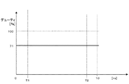
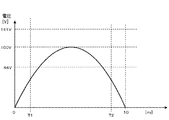
図7は、本実施の形態1における平均電圧値を用いた時のキャリア周期毎におけるPWMデューティ率の推移の一部(半波)を示すグラフである。図8は、本実施の形態1における平均電圧値を用いた時のモータに印加されるキャリア周期毎の平均電圧推移の一部(半波)を示すグラフである。図9は、本実施の形態1における平均電圧値を用いた時のモータに流れる電流推移の一部(半波)を示す波形図である。 FIG. 7 is a graph showing a part (half wave) of the transition of the PWM duty ratio for each carrier period when the average voltage value in the first embodiment is used. FIG. 8 is a graph showing a part (half wave) of the average voltage transition for each carrier cycle applied to the motor when the average voltage value in the first embodiment is used. FIG. 9 is a waveform diagram showing a part (half wave) of a transition of current flowing in the motor when the average voltage value in the first embodiment is used.
ここで、本実施の形態1においては、電源周波数が50Hzで、平均電圧を算出する時間を前述の如く50ミリ秒とした場合について説明する。したがって、電源周期が安定していることを前提にすれば、50ミリ秒と10ミリ秒の各平均電圧は等しいため、以下の説明では便宜上、10ミリ秒の区間の図を用いて説明する。 Here, in the first embodiment, a case will be described in which the power supply frequency is 50 Hz and the time for calculating the average voltage is 50 milliseconds as described above. Therefore, assuming that the power supply cycle is stable, the average voltages of 50 milliseconds and 10 milliseconds are equal, and therefore, in the following description, description will be made with reference to a section of 10 milliseconds for convenience.
まず、平均電圧取得手段114によって演算される平均電圧は、前述の(数1)式から約90Vとなり、モータ105へ64Vを出力するのに必要なデューティは約71%と計算される。従来の如く直流母線間電圧をデューティ演算に用いた場合は、デューティ(率)が図5に示すように変動するが、本実施の形態1においては、平均電圧を演算に用いているため、一キャリア周期におけるデューティ(率)は図7に示すように0ミリ秒から10ミリ秒の区間全てに亘って一定となる。
First, the average voltage calculated by the average
その結果、モータ105に印加されるキャリア周期毎の平均電圧推移は、図8に示すように、図3に示す直流母線間電圧(整流回路102の出力電圧)の推移の値を約0.71倍したものとほぼ一致し、これは整流回路102の入力側である単相交流電源101の電圧推移とも略一致している。
As a result, as shown in FIG. 8, the average voltage transition for each carrier cycle applied to the
したがって、モータ105に印加される電圧が正弦波状に推移し、モータ105に流れる総電流の推移も図9に示すように正弦波状となり、高調波成分が大きく改善され、単相交流電源101に流れる電流波形も高調波成分が大きく改善された波形となる。
Therefore, the voltage applied to the
ただし、単相交流電源101と一致するのは電源周期の中で目標値が変化しなかった場合、すなわちモータ105への印加電圧を維持している条件の時だけであり、次の制御のために平均電圧取得手段114の演算動作によって平均電圧が変化する等、条件が変化した場合は前記目標値も変化する。
However, it coincides with the single-phase
その場合は、その目標値の変化に応じてモータ105に印加しようとする電圧が単相交流電源101の1周期内で変化し、その変化に起因して前述の正弦波状から乱れた波形に変化する。
In that case, the voltage to be applied to the
その結果、モータ105に流れる総電流も正弦波とは異なり、高調波成分を多く含んだ電流波形となる。モータ105の総電流が高調波を多く含んだ電流波形となることにより、単相交流電源101に流れる電流も高調波を多く含んだ電流波形となる。
As a result, the total current flowing through the
つまり、モータ105へ流す総電流の目標値が一定の時に電圧降下が生じると、その電圧降下に伴って、モータ105に流れる実総電流は低下する。この時に、特にモータ105の回転数が低速域にある場合、インバータ104のモータ105に供給する電流のデューティを単相交流電源101の電源周期の2倍よりも高い周波数で出力制御すると、モータ105への供給電流を多く流そうとし、これに起因してモータ105に印加しようとする電圧が増加し、その結果、正弦波状から大きく乱れた波形の電圧を印加してしまい、これに起因してモータ105の総電流および単相交流電源101の電流波形に高調波電流成分を含んでしまうためである。
That is, if a voltage drop occurs when the target value of the total current flowing to the
本実施の形態1においては、モータ105に印加しようとする電圧を決定するために、目標とする電流値と比較して差を求める電流に、モータ105へ供給する総電流の平均値を用いている。このモータ105の総電流の平均値は、平均電圧取得手段114と同様に、国内商用電源周波数の50Hzと60Hzの公倍数である期間50msの合計を50msで除算し求めているため、単相交流電源101の電源周期に依存して変化することがない。
In the first embodiment, in order to determine the voltage to be applied to the
このように、目標電流と、モータ105に印加すべき電圧を決定する電流(モータ105の総電流)の平均値との差が、単相交流電源101の電源周期に依存せず、モータ105には、単相交流電源101を全波整流した電圧波形と同期した波形の電圧を印加することになり、電流も電源電圧を全波整流した電圧波形と相似な波形で流れることとなる。つまり高調波電流が改善された電流が、単相交流電源101に流れることとなる。
As described above, the difference between the target current and the average value of the current (total current of the motor 105) that determines the voltage to be applied to the
本実施の形態1においては、直流母線V1、V2間電圧の平均値と、モータ105を流れる総電流の平均値を求めるに当り、50ms間(半波)での平均値を採用しているが、単相交流電源101の電源周期(周波数)の2倍以下の周期で平均値を求める制御とすることにより、モータ105への印加電圧は電源周期と略同期した波形となり、高調波成分を改善した電流波形が得られる。
In the first embodiment, the average value for 50 ms (half wave) is used to obtain the average value of the voltage between the DC buses V1 and V2 and the average value of the total current flowing through the
かかる制御の応答性は、単相交流電源101における電源周期(周波数)の2倍以下の周期(周波数)ということで、速やかな応答性とは言えないが、家電製品等の分野においては、一般的に負荷の変化が大きくないため、十分その変動に追従できる範囲であり、問題とならない。
The response of such control is a cycle (frequency) that is twice or less the power cycle (frequency) of the single-phase
以上のように、本実施の形態1においては、単相交流電源101と、単相交流電源101から入力される電流を整流して直流に変換し、出力する整流回路102と、整流回路102から出力される直流を入力とするインバータ104と、インバータ104により駆動されるモータ105と、モータ105の現在の運転状態を把握する運転状態把握手段113と、モータ105の目標運転状態を設定する目標値演算手段122と、目標値演算手段122による設定運転状態と運転状態把握手段113により把握された現在の運転状態の差を基にインバータ104の駆動制御信号を出力する制御手段117を備え、制御手段117の出力周期の範囲を、単相交流電源101における電源周波数の2倍以下の周波数範囲で変化させるようにしたものである。
As described above, in the first embodiment, the single-phase alternating
したがって、モータ105へ印加する総電圧は、単相交流電源101の電圧波形と略同期することとなり、その結果、特にモータ105の回転が低速域にあるときの単相交流電源101の電流波形が改善され、容量の大きなリアクタ等を用いることなく、単純な構成で単相交流入力(インバータ104への入力)の電流波形が改善でき、低コストかつ小型化のモータ駆動装置を提供することができる。
Therefore, the total voltage applied to the
また、整流回路102の直流母線V1、V2間に、小容量のコンデンサ103を接続することにより、電圧低下時においてモータ105からの回生エネルギーを蓄え利用することが可能となる。その結果、モータ105の起動に一層大きなトルクを発生させることが可能となる。
Further, by connecting a small-
さらに、運転状態把握手段113を、整流回路102の直流母線V1、V2間電圧の平均値を取得する平均電圧取得手段114と、モータ105に流れる電流の平均値を取得する平均電流取得手段115を具備する構成とし、制御手段117が、モータ105を本来の運転状態とするべく演算決定した目標運転電流値と、平均電流取得手段115により取得、演算された平均電流との差分によってモータ105への印加電圧を決定し、この決定した電圧と、平均電圧取得手段114によって取得、演算された電圧からインバータ104の出力を制御することにより、外乱等のノイズに強い運転が可能となり、この種制御回路の常套手段として設けられるノイズフィルタを小型のものとすることができ、より低コストでより小型のモータ駆動装置を提供することができる。
Further, the operation state grasping means 113 includes an average voltage acquisition means 114 for acquiring an average value of the voltages between the DC buses V1 and V2 of the
また、制御手段117によるインバータ104へ出力する平均電流(デューティ)を決定は、制御手段117が、目標値演算手段122により設定されたモータ105の目標運転電流と電流検出手段120により検出された電流とで比例積分制御を行い、決定するもので、その比例積分制御に用いる比例ゲインと積分ゲインの応答周波数(周期)を、電源周波数(周期)の2倍以下とすることにより、モータ105に流れる電流波形を電流値の変動が小さい波形とすることができ、かかる制御は、容量が小さい平滑用コンデンサを用いた回路の制御方法から極めて容易に変更ができる。
Further, the average current (duty) output to the
その結果、より低コストで容量の大きなリアクタ等を用いることのない小型のモータ駆動装置を提供することができる。 As a result, it is possible to provide a small motor driving device that is less expensive and does not use a reactor having a large capacity.
また、直流母線V1、V2の平均電圧を検出する平均電圧取得手段114を、電圧を検出する電圧検出手段118と、平均電圧演算手段119で構成し、また運転状態把握手段113を、モータ105の電流を取得する電流検出手段120と、該電流検出手段120により検出された電流と電圧検出手段118により検出された電圧とからモータ105の位置を検出するモータ位相演算手段116で構成することにより、モータ位相を精度良く推定するために必要な電圧検出手段118を、平均電圧を検出するための電圧検出手段と兼用しているため、部品数の削減が図れ、低コストで精度の高い位置検出手段を実現することができる。
Further, the average voltage acquisition means 114 for detecting the average voltage of the DC buses V1 and V2 is constituted by the voltage detection means 118 for detecting the voltage and the average voltage calculation means 119, and the operation state grasping means 113 is provided for the
また、圧縮機108を駆動するモータ105の場合は、電圧の変動によってモータ105にトルク変動が発生しても、圧縮機108の慣性モーメントが大きいことからモータ105への影響は小さく、その結果、より安定した駆動が可能となる。
In the case of the
さらに、圧縮機108をレシプロ型の圧縮機としているため、構造上、スクロール型圧縮機やロータリ型圧縮機等よりさらに慣性モーメントが大きく、さらに安定した駆動が可能となる。
Furthermore, since the
また、圧縮機108が圧縮する冷媒をR600aとしているため、冷蔵庫等で一般的に採用されたR134aと比較して冷凍能力が低く、同等の冷凍能力を得るためには、圧縮機108の気筒容積を大きくする必要がある。かかる構成は、慣性モーメントがさらに増加することとなるので、非常に安定した運転を行うことができる。
In addition, since the refrigerant compressed by the
さらに、モータ駆動装置は、モータ105に印加される電圧波形を正弦波状に推移させるため、モータ105に流れる総電流の推移も高調波成分が改善された制限波状となる。
Furthermore, since the motor drive device changes the voltage waveform applied to the
したがって、前記モータ駆動装置を具備する圧縮機108を、凝縮器109、減圧器110、蒸発器111等とともに構成される冷凍空調システム(冷凍サイクル)に設け、この冷凍空調システムを冷蔵庫に採用することにより、空調機器よりも厳しい高調波規制を満足する冷蔵庫が得られる。しかも、前記モータの駆動装置は、小型であるので、冷蔵庫の庫内容積率を高めることができ、従来と同じ外形寸法でより収納容量の多い使い勝手の良い冷蔵庫を提供できることとなる。
Therefore, the
また、前記冷凍空調システムを空気調和機に適用することにより、空気調和機の小型化が可能となり、しかも、低コストで高調波を改善した空気調和機を構成できる。そのため、高調波による他の機器への影響も少なくなり、空気調和機における設置スペースの自由度を高めることができる。 Further, by applying the refrigeration and air conditioning system to an air conditioner, the air conditioner can be downsized, and an air conditioner with improved harmonics can be configured at low cost. Therefore, the influence of other harmonics on other devices is reduced, and the degree of freedom of installation space in the air conditioner can be increased.
前記モータの駆動装置は、冷凍空調システム以外にも用途展開が可能で、適用した各種機器に特有の作用効果をもたらすものである。 The motor drive device can be used for applications other than the refrigerating and air-conditioning system, and brings about a function and effect peculiar to various applied devices.
モータ105を、送風装置のファン駆動用として用いた場合、小型軽量化したモータ駆動装置であることに起因して送風装置自体を従来の送風装置に比べて小型化および軽量化でき、可搬性の高い送風装置を提供することができる。
When the
また、モータ105を、衣類の汚れ等を洗濯する電気洗濯機のドラム(洗濯兼脱水槽)の回転駆動用として用いた場合、小型化したモータ制御装置であることに起因して洗濯機のドラム容積率を高くすることが可能となり、従来の電気洗濯機と同じ外形寸法で洗濯兼脱水槽の大容量化が可能となる。
In addition, when the
同様に、モータ105を、湿った衣類等を乾燥する電気乾燥機の乾燥ドラムの回転駆動用として用いた場合も、小型化したモータ制御装置であることに起因して乾燥機の乾燥ドラム容積率を高くすることが可能となり、従来の電気乾燥機と同じ外形寸法でドラムの大容量化が可能となる。
Similarly, when the
さらに、モータ105を、床等のごみを吸引する電気掃除機のファン駆動用として用いた場合も同様に、小型軽量化したモータ制御装置であることに起因して掃除機本体を従来の掃除機に比べて小型化および軽量化することができ、その結果、可搬性が高く、ユーザにとってハンドリングが容易な使い勝手のよい電気掃除機を提供することができる。
Further, when the
以上のように、本発明にかかるモータの駆動装置は、小型・低コストで高調波抑制が可能となるので、冷凍空調システム以外にも、AV機器(特に小型機器)等のようにモータが非常に小さくてセンサをつけることが困難な機器や回路を非常に小型化したい場合等の用途にも適用できる。 As described above, since the motor drive device according to the present invention can suppress harmonics in a small size and at low cost, in addition to the refrigerating and air-conditioning system, the motor is very much like AV equipment (particularly small equipment). It can also be applied to applications such as when it is desired to miniaturize a device or circuit that is too small to attach a sensor.
101 単相交流電源
102 整流回路
103 コンデンサ
104 インバータ
105 モータ
106 圧縮要素
107 密閉容器
108 圧縮機
109 凝縮器
110 減圧器
111 蒸発器
112 庫内
113 運転状態把握手段
114 平均電圧取得手段
115 平均電流取得手段
116 モータ位相演算手段
117 制御手段
118 電圧検出手段
119 平均電圧演算手段
120 電流検出手段
121 平均電流演算手段
122 オイル
123 冷媒
124 固定子
125 回転子
126 主軸部
127 偏芯軸部
128 クランクシャフト
129 圧縮室
130 シリンダ
131 ピストン
132 連結手段
DESCRIPTION OF
Claims (11)
Priority Applications (1)
| Application Number | Priority Date | Filing Date | Title |
|---|---|---|---|
| JP2006212021A JP2008043012A (en) | 2006-08-03 | 2006-08-03 | Motor driving device |
Applications Claiming Priority (1)
| Application Number | Priority Date | Filing Date | Title |
|---|---|---|---|
| JP2006212021A JP2008043012A (en) | 2006-08-03 | 2006-08-03 | Motor driving device |
Publications (1)
| Publication Number | Publication Date |
|---|---|
| JP2008043012A true JP2008043012A (en) | 2008-02-21 |
Family
ID=39177426
Family Applications (1)
| Application Number | Title | Priority Date | Filing Date |
|---|---|---|---|
| JP2006212021A Pending JP2008043012A (en) | 2006-08-03 | 2006-08-03 | Motor driving device |
Country Status (1)
| Country | Link |
|---|---|
| JP (1) | JP2008043012A (en) |
Cited By (5)
| Publication number | Priority date | Publication date | Assignee | Title |
|---|---|---|---|---|
| JP2009232681A (en) * | 2008-03-20 | 2009-10-08 | Ls Industrial Systems Co Ltd | Multilevel inverter |
| JP2009281538A (en) * | 2008-05-23 | 2009-12-03 | Mitsubishi Electric Corp | Control device of automatic transmission |
| JP2014150716A (en) * | 2011-05-23 | 2014-08-21 | Mitsubishi Electric Corp | Brushless dc motor and ventilation blower |
| JP2016086639A (en) * | 2016-02-02 | 2016-05-19 | 日立工機株式会社 | Electric tool |
| US9793847B2 (en) | 2011-03-18 | 2017-10-17 | Hitachi Koki Co., Ltd. | Electric power tool |
Citations (7)
| Publication number | Priority date | Publication date | Assignee | Title |
|---|---|---|---|---|
| JP2002051589A (en) * | 2000-07-31 | 2002-02-15 | Isao Takahashi | Controller for inverter for drive of motor |
| JP2002199744A (en) * | 2000-12-27 | 2002-07-12 | Daikin Ind Ltd | Inverter-protecting method and device thereof |
| JP2005020986A (en) * | 2002-12-12 | 2005-01-20 | Matsushita Electric Ind Co Ltd | Motor control device |
| JP2005151744A (en) * | 2003-11-18 | 2005-06-09 | Matsushita Electric Ind Co Ltd | Motor drive unit |
| JP2006034001A (en) * | 2004-07-16 | 2006-02-02 | Matsushita Electric Ind Co Ltd | Drive unit for brushless dc motor |
| JP2006050805A (en) * | 2004-08-05 | 2006-02-16 | Matsushita Electric Ind Co Ltd | Brushless dc motor drive device |
| JP2006149048A (en) * | 2004-11-18 | 2006-06-08 | Matsushita Electric Ind Co Ltd | Ac power supply direct-coupling brushless dc motor and electrical device equipped therewith |
-
2006
- 2006-08-03 JP JP2006212021A patent/JP2008043012A/en active Pending
Patent Citations (7)
| Publication number | Priority date | Publication date | Assignee | Title |
|---|---|---|---|---|
| JP2002051589A (en) * | 2000-07-31 | 2002-02-15 | Isao Takahashi | Controller for inverter for drive of motor |
| JP2002199744A (en) * | 2000-12-27 | 2002-07-12 | Daikin Ind Ltd | Inverter-protecting method and device thereof |
| JP2005020986A (en) * | 2002-12-12 | 2005-01-20 | Matsushita Electric Ind Co Ltd | Motor control device |
| JP2005151744A (en) * | 2003-11-18 | 2005-06-09 | Matsushita Electric Ind Co Ltd | Motor drive unit |
| JP2006034001A (en) * | 2004-07-16 | 2006-02-02 | Matsushita Electric Ind Co Ltd | Drive unit for brushless dc motor |
| JP2006050805A (en) * | 2004-08-05 | 2006-02-16 | Matsushita Electric Ind Co Ltd | Brushless dc motor drive device |
| JP2006149048A (en) * | 2004-11-18 | 2006-06-08 | Matsushita Electric Ind Co Ltd | Ac power supply direct-coupling brushless dc motor and electrical device equipped therewith |
Cited By (11)
| Publication number | Priority date | Publication date | Assignee | Title |
|---|---|---|---|---|
| JP2009232681A (en) * | 2008-03-20 | 2009-10-08 | Ls Industrial Systems Co Ltd | Multilevel inverter |
| US8159840B2 (en) | 2008-03-20 | 2012-04-17 | Ls Industrial Systems Co., Ltd. | Multilevel inverter |
| JP2009281538A (en) * | 2008-05-23 | 2009-12-03 | Mitsubishi Electric Corp | Control device of automatic transmission |
| JP4536133B2 (en) * | 2008-05-23 | 2010-09-01 | 三菱電機株式会社 | Control device for automatic transmission |
| US8058834B2 (en) | 2008-05-23 | 2011-11-15 | Mitsubishi Electric Corporation | Control device for automatic transmission |
| US9793847B2 (en) | 2011-03-18 | 2017-10-17 | Hitachi Koki Co., Ltd. | Electric power tool |
| US10033323B2 (en) | 2011-03-18 | 2018-07-24 | Hitachi Koki Co., Ltd. | Electric power tool |
| US11070160B2 (en) | 2011-03-18 | 2021-07-20 | Koki Holdings Co., Lid. | Electric power tool |
| US11770088B2 (en) | 2011-03-18 | 2023-09-26 | Koki Holdings Co., Ltd. | Electric power tool |
| JP2014150716A (en) * | 2011-05-23 | 2014-08-21 | Mitsubishi Electric Corp | Brushless dc motor and ventilation blower |
| JP2016086639A (en) * | 2016-02-02 | 2016-05-19 | 日立工機株式会社 | Electric tool |
Similar Documents
| Publication | Publication Date | Title |
|---|---|---|
| JP4596866B2 (en) | Motor drive device | |
| ES2300538T3 (en) | MOTOR CONTROL DEVICE. | |
| US8169180B2 (en) | Motor controller of air conditioner | |
| EP1503491B1 (en) | Motor driving apparatus | |
| US8120299B2 (en) | Motor controller of air conditioner | |
| JP4957223B2 (en) | Motor starter | |
| JP4416486B2 (en) | Motor control device | |
| JP2005198376A (en) | Method of driving brushless dc motor, and its device | |
| JP2011010430A (en) | Motor drive device | |
| KR101561922B1 (en) | Method for controlling motor of air conditioner | |
| JP2008043012A (en) | Motor driving device | |
| JP2011010432A (en) | Motor drive device | |
| US9714782B2 (en) | Device and method for controlling compressor, and refrigerator including same | |
| JP2008104315A (en) | Motor driving device | |
| KR20140108956A (en) | Power converting apparatus and air conditioner having the same | |
| JP2008099485A (en) | Motor drive device | |
| JP2008005639A (en) | Method and device for driving brushless dc motor | |
| JP2008043014A (en) | Motor driving device | |
| WO2022172419A1 (en) | Power conversion device, motor drive device, and air conditioner | |
| JP2006109624A (en) | Drive device for brushless dc motor | |
| JP2008043013A (en) | Motor driving device | |
| JP2008109722A (en) | Motor drive | |
| JP4606768B2 (en) | Motor drive device | |
| KR20090081914A (en) | Motor controller of air conditioner | |
| JP2007143332A (en) | Motor drive device, and freezer provided therewith |
Legal Events
| Date | Code | Title | Description |
|---|---|---|---|
| A621 | Written request for application examination |
Free format text: JAPANESE INTERMEDIATE CODE: A621 Effective date: 20090625 |
|
| RD01 | Notification of change of attorney |
Free format text: JAPANESE INTERMEDIATE CODE: A7421 Effective date: 20090714 |
|
| A977 | Report on retrieval |
Free format text: JAPANESE INTERMEDIATE CODE: A971007 Effective date: 20110629 |
|
| A131 | Notification of reasons for refusal |
Free format text: JAPANESE INTERMEDIATE CODE: A131 Effective date: 20110830 |
|
| A521 | Written amendment |
Free format text: JAPANESE INTERMEDIATE CODE: A523 Effective date: 20111031 |
|
| A131 | Notification of reasons for refusal |
Free format text: JAPANESE INTERMEDIATE CODE: A131 Effective date: 20120703 |
|
| A02 | Decision of refusal |
Free format text: JAPANESE INTERMEDIATE CODE: A02 Effective date: 20121106 |