EP3067565B1 - Vakuumpumpe - Google Patents
Vakuumpumpe Download PDFInfo
- Publication number
- EP3067565B1 EP3067565B1 EP15158925.6A EP15158925A EP3067565B1 EP 3067565 B1 EP3067565 B1 EP 3067565B1 EP 15158925 A EP15158925 A EP 15158925A EP 3067565 B1 EP3067565 B1 EP 3067565B1
- Authority
- EP
- European Patent Office
- Prior art keywords
- groove
- vacuum pump
- base element
- depression
- housing
- Prior art date
- Legal status (The legal status is an assumption and is not a legal conclusion. Google has not performed a legal analysis and makes no representation as to the accuracy of the status listed.)
- Active
Links
- 238000000034 method Methods 0.000 claims description 6
- 238000001125 extrusion Methods 0.000 claims description 3
- 230000002093 peripheral effect Effects 0.000 claims 1
- 238000009434 installation Methods 0.000 description 4
- 230000008878 coupling Effects 0.000 description 2
- 238000010168 coupling process Methods 0.000 description 2
- 238000005859 coupling reaction Methods 0.000 description 2
- 238000003754 machining Methods 0.000 description 2
- 125000006850 spacer group Chemical group 0.000 description 2
- 238000003892 spreading Methods 0.000 description 2
- 238000001816 cooling Methods 0.000 description 1
- 238000004049 embossing Methods 0.000 description 1
- 238000004519 manufacturing process Methods 0.000 description 1
- 230000000149 penetrating effect Effects 0.000 description 1
- 239000011265 semifinished product Substances 0.000 description 1
- XLYOFNOQVPJJNP-UHFFFAOYSA-N water Substances O XLYOFNOQVPJJNP-UHFFFAOYSA-N 0.000 description 1
Images
Classifications
-
- F—MECHANICAL ENGINEERING; LIGHTING; HEATING; WEAPONS; BLASTING
- F04—POSITIVE - DISPLACEMENT MACHINES FOR LIQUIDS; PUMPS FOR LIQUIDS OR ELASTIC FLUIDS
- F04D—NON-POSITIVE-DISPLACEMENT PUMPS
- F04D19/00—Axial-flow pumps
- F04D19/02—Multi-stage pumps
- F04D19/04—Multi-stage pumps specially adapted to the production of a high vacuum, e.g. molecular pumps
-
- F—MECHANICAL ENGINEERING; LIGHTING; HEATING; WEAPONS; BLASTING
- F04—POSITIVE - DISPLACEMENT MACHINES FOR LIQUIDS; PUMPS FOR LIQUIDS OR ELASTIC FLUIDS
- F04D—NON-POSITIVE-DISPLACEMENT PUMPS
- F04D17/00—Radial-flow pumps, e.g. centrifugal pumps; Helico-centrifugal pumps
- F04D17/08—Centrifugal pumps
- F04D17/16—Centrifugal pumps for displacing without appreciable compression
- F04D17/168—Pumps specially adapted to produce a vacuum
-
- F—MECHANICAL ENGINEERING; LIGHTING; HEATING; WEAPONS; BLASTING
- F04—POSITIVE - DISPLACEMENT MACHINES FOR LIQUIDS; PUMPS FOR LIQUIDS OR ELASTIC FLUIDS
- F04D—NON-POSITIVE-DISPLACEMENT PUMPS
- F04D29/00—Details, component parts, or accessories
- F04D29/40—Casings; Connections of working fluid
- F04D29/403—Casings; Connections of working fluid especially adapted for elastic fluid pumps
-
- F—MECHANICAL ENGINEERING; LIGHTING; HEATING; WEAPONS; BLASTING
- F04—POSITIVE - DISPLACEMENT MACHINES FOR LIQUIDS; PUMPS FOR LIQUIDS OR ELASTIC FLUIDS
- F04D—NON-POSITIVE-DISPLACEMENT PUMPS
- F04D29/00—Details, component parts, or accessories
- F04D29/60—Mounting; Assembling; Disassembling
- F04D29/601—Mounting; Assembling; Disassembling specially adapted for elastic fluid pumps
Definitions
- the present invention relates to a vacuum pump with a housing.
- Vacuum pumps are used in a wide variety of applications. They can be coupled with a wide variety of devices to provide the vacuum required for a particular process. The respective mounting or installation situation depends largely on the available installation space.
- vacuum pumps can be equipped with a variety of different accessories. These include fans, air baffles, heat sinks or components of a water cooling system.
- threaded holes are conventionally made in the housing of the vacuum pump at the required points. This enables the aforementioned components or the vacuum pump to be reliably attached in the desired installation position.
- the holes must be placed specifically for each application.
- the EP 2 133 581 A2 , JP 61-82013 and US 2008/0309071 A1 each disclose a vacuum pump with a flange with which they can be attached to a recipient to be evacuated.
- the respective flange comprises a groove in which a fastening means can engage.
- the EP 2 789 889 A1 also describes a vacuum pump with a mounting flange.
- the vacuum pump should be adaptable to the prevailing circumstances in the simplest possible way.
- the housing of the vacuum pump has at least one groove-like recess, with which at least one base element for fastening components to the vacuum pump or the vacuum pump to other units is coupled. Additionally or alternatively, the housing is connected to an element which has at least one groove-like connection to which the above-mentioned base element is coupled.
- the element can, for example, be a bar connected to the housing in any way and provided with the groove-like depression. In principle, the shape and size of the element and the number and configuration of the depressions provided on the element can be adapted to the respective requirements.
- the accessory components required in each case are fixed according to the invention to the housing via the base element coupled to the recess.
- the housing In order to adapt the vacuum pump to the customer-specific conditions or requirements, the housing generally does not have to be machined more or at least significantly less, but it is usually sufficient to adapt the base element.
- the base element is detachably connected to the groove-like depression. If the vacuum pump is to be installed at another location and / or is to be connected to other accessory components, no additional fastening points have to be created directly on the housing of the pump, since the base element can be replaced quickly and easily.
- the base element can be inserted into the groove-like recess.
- the groove-like depression can be open on one side. It is understood that the one-sided opening of the groove-like depression can be closed with a cap or the like if necessary.
- the base element such that it can be clipped into the groove-like recess.
- Such a configuration is particularly advantageous for pre-assembly, since it enables simple and quick coupling of the base element to the groove-like recess.
- the groove-like depression extends at least in sections, in particular completely parallel to a longitudinal axis of the housing.
- the groove-like depression (or an additional groove-like depression) can also extend at least in sections, in particular completely, in the circumferential direction of the housing.
- the course and the arrangement of the groove can be selected so that the greatest possible flexibility with regard to the provision of fastening points is achieved. The same applies to the number of groove-like depressions provided on the housing.
- the base element can essentially be completely accommodated by the groove-like depression, so that the base element does not form a contour which protrudes from the housing and which may be disruptive.
- the base element has or forms a contact surface that is spaced from the surface of the housing.
- the basic element - in addition to its function as a flexibly configurable component of the fastening concept - serves as a spacer, so that the housing of the pump is protected from surface damage (eg scratches).
- the groove-like recess has an undercut which interacts with at least one bulge or a projection of the base element.
- the groove-like recess is T-shaped in a cross section perpendicular to the longitudinal extent.
- the base element can have essentially the same length as the groove-like depression, so that it practically completely fills it at least in the longitudinal direction. In principle, however, it is of course also possible to use a shorter base element. In this case, several basic elements can also be used to provide the required number of fastening points.
- the base element can be freely displaceable in the groove-like depression and can only be fixed in its intended position during assembly, for example by a force fit.
- the base element can comprise a cover profile which essentially covers and / or closes the groove-like depression.
- the base element has at least one threaded bore, with the aid of which the vacuum pump can be attached to other units and / or components can be attached to the vacuum pump.
- the base element can also have a recess which extends along its longitudinal extent.
- the base element is a screw strip into which a screw can be screwed in at any point.
- the housing is at least partially shaped by an extrusion process, the groove-like depression already being in the Is brought into the housing during this process.
- the groove-like recess can also provide other advantageous functions.
- it can serve as a cable duct.
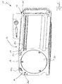
- Fig. 1 shows a vacuum pump 10, which is a turbopump, for example.
- a vacuum pump 10 which is a turbopump, for example.
- the grooves 14 extend essentially completely along the longitudinal extent of a housing base body 16, which on its in Fig. 1 right axial end is closed with a housing end section 18 and at its left end with a cover 20.
- the housing base body 16 accommodates all the essential functional components of the vacuum pump 10.
- Base elements 22a, 22b, 22c and 22d are arranged in the grooves 14, the design and function of which will be explained in more detail below.
- the housing end section 18 also has a groove 14 'into which, if necessary, a base element in the manner of the base elements 22a, 22b, 22c, 22d can be inserted or inserted.
- the arrangement and / or configuration of the grooves 14, 14 ′ can be selected such that essentially all configurations of fastening points that are reasonably expected / required can be provided.
- the housing base body 16 of the housing 12 has been produced in the exemplary embodiment by an extrusion process.
- the grooves 14 can be made directly in the semifinished product.
- the groove 14 'of the housing end section 18 of the housing 12 can, for example, have been produced by a machining process.
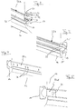
- Fig. 2 shows a section of the housing base body 16 with a portion of the base element 22a in an enlargement.
- the groove 14 has a substantially T-shaped cross section, which is formed by projections 24.
- the protrusions 24 form undercuts which cooperate with bulges 26 which are provided on the base element 22a.
- the bulges 26 are arranged on legs 30 of the base element 22a projecting into the groove from a cover section 28.
- the base element 22a is thus a profile piece with an essentially U-shaped basic shape.
- the base element 22a covers the groove 14 essentially completely, so that it is protected against dirt. If necessary, cables can be routed in the groove 14.
- the base element 22a serves in particular to provide customer-specific or application-specific fastening points.
- bores are made in the cover section 28 of the base element 22a at the desired locations (not shown), into which fastening screws (not shown) can be screwed.
- the fastening screws cooperate with spreading sections 32 which project inwardly from the legs 30 and are arranged at an angle to them.
- the expansion sections 32 cause the screwed-in fastening screws to push the legs 32 apart, as a result of which the bulges 26 interact even more efficiently with the projections 24 forming the undercuts in order to reliably couple the base element 22a to the housing 12.
- the bore in the cover section 28 can be drilled in any position before or after the base element 22a has been introduced into the groove 14.
- the base element 22a can be introduced into the groove 14 by pushing it in from the side or - if the base element 22a is correspondingly elastic - by clipping it in.
- the base element 22a in which the cover section 28 is located essentially in the same plane as the sections of the surface of the housing 12 adjacent to the groove 14, the base element can protrude from the groove 14.
- the cover section of such a base element could then be used as a contact surface, so that the component to be fastened does not lie directly on the housing 12.
- the part of the base element protruding from the groove 14 then forms a spacer in order to protect the housing 12.
- Fig. 3 shows a further embodiment 22b of the base element, which corresponds at least functionally to a screw strip.
- Projections 24 'on the outside of the legs 30 of the base element 20b interact with the projections 24 of the groove 14.
- Fastening screws can be screwed into the base element 22b, which is also designed as a profile piece, at any point, which in turn forces the legs 30 and the base element apart 22b is ultimately securely fixed in the groove 14.
- the base element 22b can also be inserted into the groove 14 by pushing it in or clipping it in. It is generally not necessary to prepare the base element 22b.
- the in Fig. 4 Embodiment 22c shown of the base element provided discrete bores 34 at the respectively required locations.
- the bores 34 are threaded bores. If a fastening screw is inserted into the threaded bores 34 in order to fasten a component to the housing 12 and / or to fasten the vacuum pump 10 to another unit, the strip-like base element 22c is pressed against the projections 24, so that a reliable frictional connection is produced.
- individual sliding blocks 22d can also be provided (see Fig. 5 ), whose mode of operation essentially corresponds to that of the base element 22c.
- the fastening concept according to the invention which is based on a coupling of an inexpensive base element and a groove-like depression made in the housing of the vacuum pump, enables fastening points to be provided very flexibly without having to compromise on the reliability of the fastening.
Description
- Die vorliegende Erfindung betrifft eine Vakuumpumpe mit einem Gehäuse.
- Vakuumpumpen gelangen in den unterschiedlichsten Anwendungen zum Einsatz. Sie können mit den verschiedensten Geräten gekoppelt werden, um ein für einen bestimmten Prozess benötigtes Vakuum bereitzustellen. Die jeweilige An- oder Einbausituation hängt dabei maßgeblich von dem zur Verfügung stehenden Bauraum ab. Außerdem können Vakuumpumpen mit einer Vielzahl von unterschiedlichen Zubehörbauteilen versehen werden. Hierzu gehören unter anderem Lüfter, Luftleitbleche, Kühlkörper oder Komponenten einer Wasserkühlung.
- Zur Befestigung von Komponenten an der Vakuumpumpe oder der Vakuumpumpe an anderen Einheiten werden in das Gehäuse der Vakuumpumpe herkömmlicherweise an den jeweils erforderlichen Stellen Gewindebohrungen eingebracht. Dies ermöglicht die zuverlässige Befestigung der genannten Komponenten bzw. der Vakuumpumpe in der jeweils gewünschten Einbaulage. Allerdings müssen die Bohrungen für jeden Anwendungsfall spezifisch platziert werden.
- Die
EP 2 133 581 A2 ,JP 61-82013 US 2008/0309071 A1 offenbaren jeweils eine Vakuumpumpe mit einem Flansch, mit dem sie an einem zu evakuierenden Rezipienten befestigbar sind. Der jeweilige Flansch umfasst eine Nut, in die ein Befestigungsmittel eingreifen kann. DieEP 2 789 889 A1 beschreibt ebenfalls eine Vakuumpumpe mit einem Befestigungsflansch. - Es ist eine Aufgabe der vorliegenden Erfindung, eine Vakuumpumpe zu schaffen, die auf einfache Weise flexibel einsetzbar ist. Mit anderen Worten soll die Vakuumpumpe auf möglichst einfache Weise an die jeweils vorliegenden Umstände anpassbar sein.
- Diese Aufgabe wird durch eine Vakuumpumpe mit den Merkmalen des Anspruchs 1 gelöst.
- Erfindungsgemäß weist das Gehäuse der Vakuumpumpe zumindest eine nutartige Vertiefung auf, mit der zumindest ein Basiselement zur Befestigung von Komponenten an der Vakuumpumpe oder der Vakuumpumpe an anderen Einheiten gekoppelt ist. Zusätzlich oder alternativ ist das Gehäuse mit einem Element verbunden, das zumindest eine nutartige Verbindung aufweist, mit der das vorstehend genannte Basiselement gekoppelt ist. Das Element kann beispielsweise eine mit dem Gehäuse auf beliebige Weise verbundene Leiste sein, die mit der nutartigen Vertiefung versehen ist. Grundsätzlich können die Formgebung und Größe des Elements sowie die Anzahl und Ausgestaltung der an dem Element vorgesehenen Vertiefungen an die jeweils vorliegenden Anforderungen angepasst sein.
- D.h. die jeweils erforderlichen Zubehörkomponenten werden erfindungsgemäß über das mit der Vertiefung gekoppelte Basiselement an dem Gehäuse fixiert. Analoges gilt für die Befestigung der Pumpe an anderen Einheiten. Um die Vakuumpumpe an die kundenspezifischen Bedingungen bzw. Wünsche anzupassen, muss das Gehäuse in der Regel nicht mehr oder zumindest deutlich weniger bearbeitet werden, sondern es reicht zumeist aus, das Basiselement anzupassen.
- Weitere Ausführungsformen der Erfindung sind in der Beschreibung, den Ansprüchen und den Zeichnungen angegeben.
- Gemäß einer vorteilhaften Ausführungsform ist das Basiselement lösbar mit der nutartigen Vertiefung verbunden. Wenn die Vakuumpumpe an einem anderen Ort verbaut werden soll und/oder mit anderen Zubehörkomponenten verbunden werden soll, so müssen keine zusätzlichen Befestigungspunkte direkt am Gehäuse der Pumpe geschaffen werden, da das Basiselement schnell und einfach ausgetauscht werden kann.
- Insbesondere ist das Basiselement in die nutartige Vertiefung einschiebbar. Zu diesem Zweck kann die nutartige Vertiefung einseitig offen sein. Es versteht sich, dass die einseitige Öffnung der nutartigen Vertiefung bei Bedarf mit einer Kappe oder ähnlichem geschlossen werden kann.
- Es ist auch möglich, das Basiselement so auszugestalten, dass es in die nutartige Vertiefung einklipsbar ist. Insbesondere für eine Vormontage ist eine solche Ausgestaltung vorteilhaft, da sie eine einfache und schnelle Kopplung des Basiselements mit der nutartigen Vertiefung ermöglicht.
- Die nutartige Vertiefung erstreckt sich zumindest abschnittsweise, insbesondere vollständig parallel zu einer Längsachse des Gehäuses. Die nutartige Vertiefung (oder eine zusätzliche nutartige Vertiefung) kann sich auch zumindest abschnittsweise, insbesondere vollständig in Umfangsrichtung des Gehäuses erstrecken. Grundsätzlich können der Verlauf und die Anordnung der Nut so gewählt werden, dass eine höchstmögliche Flexibilität hinsichtlich der Bereitstellung von Befestigungspunkten erreicht wird. Gleiches gilt für die Anzahl von an dem Gehäuse vorgesehenen nutartigen Vertiefungen.
- Das Basiselement kann im Wesentlichen vollständig von der nutartigen Vertiefung aufgenommen werden, so dass das Basiselement keine aus dem Gehäuse hervorstehende Kontur bildet, die eventuell störend ist.
- Alternativ kann aber auch bewusst vorgesehen sein, dass das Basiselement eine Anlagefläche aufweist oder bildet, die von der Oberfläche des Gehäuses beabstandet ist. Das Basiselement dient in diesem Fall - neben seiner Funktion als flexibel konfigurierbare Komponente des Befestigungskonzepts - als Abstandshalter, so dass das Gehäuse der Pumpe vor Oberflächenbeschädigungen (z.B. Kratzer) geschützt wird.
- Erfindungsgemäß weist die nutartige Vertiefung einen Hinterschnitt auf, der mit zumindest einer Ausbuchtung oder einem Vorsprung des Basiselements zusammenwirkt. Insbesondere ist die nutartige Vertiefung in einem Querschnitt senkrecht zu der Längserstreckung T-förmig ausgebildet.
- Das Basiselement kann im Wesentlichen die gleiche Länge wie die nutartige Vertiefung aufweisen, so dass es diese zumindest in Längsrichtung praktisch vollständig ausfüllt. Grundsätzlich ist es aber natürlich auch möglich, ein kürzeres Basiselement zu verwenden. In diesem Fall können auch mehrere Basiselemente verwendet werden, um die benötigte Anzahl von Befestigungspunkten bereit zu stellen.
- Das Basiselement kann in der nutartigen Vertiefung frei verschiebbar sein und erst bei der Montage in ihrer vorgesehenen Lage fixiert werden, beispielsweise durch einen Kraftschluss.
- Um das Eindringen von Verschmutzungen in die nutartige Vertiefung zu verhindern und der Vakuumpumpe auch eine optisch ansprechende Prägung zu geben, kann das Basiselement ein Abdeckprofil umfassen, das die nutartige Vertiefung im Wesentlichen abdeckt und/oder verschließt.
- Gemäß einer Ausführungsform weist das Basiselement zumindest eine Gewindebohrung auf, mit Hilfe derer die Vakuumpumpe an anderen Einheiten befestigbar ist und/oder Komponenten an der Vakuumpumpe befestigt werden können. Das Basiselement kann auch eine Ausnehmung aufweisen, die sich entlang deren Längserstreckung erstreckt. Beispielsweise ist das Basiselement eine Schraubleiste, in die an beliebigen Stellen eine Schraube einschraubbar ist.
- Das Gehäuse ist gemäß einer vorteilhaften Ausführungsform zumindest teilweise durch einen Strangpressprozess geformt, wobei die nutartige Vertiefung bereits im Zuge dieses Prozesses in das Gehäuse eingebracht wird. Grundsätzlich ist es auch möglich, die nutartige Vertiefung durch einen spanenden Prozess in das Gehäuse einzubringen und/oder anzupassen.
- Neben ihrer Funktion als Bestandteil des Befestigungskonzepts kann die nutartige Vertiefung auch andere vorteilhafte Funktionen bereitstellen. Beispielsweise kann sie als Kabelkanal dienen.
- Nachfolgend wird die vorliegende Erfindung rein beispielhaft anhand vorteilhafter Ausführungsformen unter Bezugnahme auf die beigefügten Zeichnungen erläutert. Es zeigen:
- Fig. 1
- eine Ausführungsform der erfindungsgemäßen Vakuumpumpe und
- Fig. 2 bis 5
- verschiedene Ausführungsformen des Basiselements.
-
Fig. 1 zeigt eine Vakuumpumpe 10, die beispielsweise eine Turbopumpe ist. Bei derartigen Pumpen kann es - wie eingangs erläutert - gewünscht sein, an deren Äußeren Zubehör anzubringen oder sie an anderen Vorrichtungen zu befestigen. Um zu verhindern, dass für jede Konfiguration und/oder Bauraumsituation kundenspezifische Gewindebohrungen in ein Gehäuse 12 der Vakuumpumpe 10 eingebracht werden müssen, ist dieses mit Nuten 14 versehen. Die Nuten 14 erstrecken sich im Wesentlichen vollständig entlang der Längserstreckung eines Gehäusegrundkörpers 16, der an seinem inFig. 1 rechten axialen Ende mit einem Gehäuseendabschnitt 18 und an seinem linken Ende mit einem Deckel 20 verschlossen ist. Der Gehäusegrundkörper 16 nimmt alle wesentlichen Funktionskomponenten der Vakuumpumpe 10 auf. In den Nuten 14 sind Basiselemente 22a, 22b, 22c bzw. 22d angeordnet, deren Gestaltung und Funktion nachfolgend noch eingehender erläutert wird. - Der Gehäuseendabschnitt 18 weist ebenfalls eine Nut 14' auf, in die bei Bedarf ein Basiselement in der Art der Basiselemente 22a, 22b, 22c, 22d eingesteckt bzw. eingeschoben werden kann.
- Es versteht sich, dass die Anordnung und/oder Ausgestaltung der Nuten 14, 14' so gewählt werden kann, dass im Wesentlichen alle vernünftigerweise zu erwartenden/benötigten Konfigurationen von Befestigungspunkten bereitgestellt werden können.
- Der Gehäusegrundkörper 16 des Gehäuses 12 ist bei dem Ausführungsbeispiel durch einen Strangpressprozess hergestellt worden. Bei diesem Herstellungsprozess können die Nuten 14 gleich direkt in das Halbzeug eingebracht werden. Die Nut 14' des Gehäuseendabschnitts 18 des Gehäuses 12 kann beispielsweise durch einen spanenden Prozess erzeugt worden sein.
-
Fig. 2 zeigt einen Ausschnitt des Gehäusegrundkörpers 16 mit einem Abschnitt des Basiselements 22a in einer Vergrößerung. Die Nut 14 weist einen im Wesentlichen T-förmigen Querschnitt auf, der durch Vorsprünge 24 gebildet wird. Die Vorsprünge 24 bilden Hinterschneidungen, die mit Ausbuchtungen 26 zusammenwirken, die an dem Basiselement 22a vorgesehen sind. Die Ausbuchtungen 26 sind an von einem Deckabschnitt 28 in die Nut ragenden Schenkeln 30 des Basiselements 22a angeordnet. Das Basiselement 22a ist somit ein Profilstück mit einer im Wesentlichen U-förmigen Grundform. Das Basiselement 22a deckt die Nut 14 im Wesentlichen vollständig ab, so dass diese vor Schmutz geschützt ist. In der Nut 14 können bei Bedarf Kabel geführt werden. - Das Basiselement 22a dient aber insbesondere dazu, kunden- oder anwendungsspezifische Befestigungspunkte bereitzustellen. Zu diesem Zweck werden an den gewünschten Stellen in den Deckabschnitt 28 des Basiselements 22a Bohrungen (nicht gezeigt) eingebracht, in die Befestigungsschrauben (nicht gezeigt) geschraubt werden können. Die Befestigungsschrauben wirken bei ihrer Montage mit von den Schenkeln 30 nach innen ragenden und geneigt zu diesen angeordneten Spreizabschnitten 32 zusammen. Die Spreizabschnitte 32 bewirken, dass die eingeschraubten Befestigungsschrauben die Schenkel 32 auseinanderdrücken, wodurch die Ausbuchtungen 26 noch effizienter mit den Hinterschnitte bildenden Vorsprüngen 24 zusammenwirken, um das Basiselement 22a zuverlässig mit dem Gehäuse 12 zu koppeln.
- Die Bohrung in dem Deckabschnitt 28 können in beliebiger Position vor oder nach dem Einbringen des Basiselements 22a in die Nut 14 eingebohrt werden. Das Einbringen des Basiselements 22a in die Nut 14 kann durch seitliches Einschieben oder - bei entsprechender Elastizität des Basiselements 22a - durch Einklipsen realisiert werden.
- Abweichend von der in
Fig. 2 gezeigten Ausgestaltung des Basiselements 22a, bei der sich der Deckabschnitt 28 im Wesentlichen in der gleichen Ebene befindet, wie die der Nut 14 benachbarten Abschnitte der Oberfläche des Gehäuses 12, kann das Basiselement aus der Nut 14 herausragen. Der Deckabschnitt eines solchen Basiselements könnte dann als Anlagefläche genutzt werden, so dass die zu befestigende Komponente nicht direkt auf dem Gehäuse 12 aufliegt. Letztlich bildet der aus der Nut 14 herausragende Teil des Basiselements dann einen Abstandshalter, um das Gehäuse 12 zu schützen. -
Fig. 3 zeigt eine weitere Ausführungsform 22b des Basiselements, die zumindest funktionell einer Schraubleiste entspricht. Vorsprünge 24' an der Außenseite der Schenkel 30 des Basiselements 20b wirken mit den Vorsprüngen 24 der Nut 14 zusammen. Befestigungsschrauben können an beliebiger Stelle in das ebenfalls als Profilstück ausgebildete Basiselement 22b eingeschraubt werden, wodurch wiederum die Schenkel 30 auseinandergedrückt werden und das Basiselement 22b letztlich sicher in der Nut 14 fixiert wird. Das Basiselement 22b ist ebenfalls durch Einschieben oder Einklipsen in die Nut 14 einbringbar. Eine Vorbereitung des Basiselements 22b ist in der Regel nicht erforderlich. - Im Gegensatz dazu sind bei der in
Fig. 4 gezeigten Ausführungsform 22c des Basiselements diskrete Bohrungen 34 an den jeweils erforderlichen Stellen vorgesehen. Die Bohrungen 34 sind Gewindebohrungen. Bringt man zur Befestigung einer Komponente an dem Gehäuse 12 und/oder zur Befestigung der Vakuumpumpe 10 an einer anderen Einheit eine Befestigungsschraube in die Gewindebohrungen 34 ein, so wird das leistenartige Basiselement 22c gegen die Vorsprünge 24 gedrückt, so dass ein zuverlässiger Kraftschluss entsteht. - Anstelle eines durchgehenden leistenförmigen Basiselements 22c, das im Wesentlichen die volle Länge der Nut 14 ausfüllt, können auch einzelne Nutensteine 22d vorgesehen sein (siehe
Fig. 5 ), deren Funktionsweise aber im Wesentlichen der des Basiselements 22c entspricht. - Das erfindungsgemäße Befestigungskonzept, das auf einer Kopplung eines kostengünstig herzustellenden Basiselements und einer in das Gehäuse der Vakuumpumpe eingebrachten nutartigen Vertiefung beruht, ermöglicht eine sehr flexible Bereitstellung von Befestigungspunkten, ohne dass Abstriche bei der Zuverlässigkeit der Befestigung gemacht werden müssen.
-
- 10
- Vakuumpumpe
- 12
- Gehäuse
- 14, 14'
- Nut
- 16
- Gehäusegrundkörper
- 18
- Gehäuseendabschnitt
- 20
- Deckel
- 22a, 22b, 22c, 22d
- Basiselement
- 24, 24'
- Vorsprung
- 26
- Ausbuchtung
- 28
- Deckabschnitt
- 30
- Schenkel
- 32
- Spreizabschnitt
- 34
- Gewindebohrung
Claims (13)
- Vakuumpumpe mit einem Gehäuse (12), das zumindest eine nutartige Vertiefung (14, 14') aufweist, und/oder das mit einem Element, das zumindest eine nutartige Vertiefung aufweist, verbunden ist, wobei mit der nutartigen Vertiefung zumindest ein Basiselement (22a, 22b, 22c, 22d) zur Befestigung von Komponenten an der Vakuumpumpe oder der Vakuumpumpe an anderen Einheiten gekoppelt ist,
dadurch gekennzeichnet, dass sich die nutartige Vertiefung (14) zumindest abschnittsweise, insbesondere vollständig parallel zu einer Längsachse des Gehäuses (12) erstreckt, und einen Hinterschnitt (24) aufweist, der mit zumindest einer Ausbuchtung (26, 24') oder einem Vorsprung des Basiselements (22a, 22b) zusammenwirkt. - Vakuumpumpe nach Anspruch 1,
dadurch gekennzeichnet, dass das Basiselement (22a, 22b, 22c, 22d) lösbar mit der nutartigen Vertiefung (14, 14') verbunden ist. - Vakuumpumpe nach Anspruch 1 oder 2,
dadurch gekennzeichnet, dass das Basiselement (22a, 22b, 22c, 22d) in die nutartige Vertiefung (14, 14'), die insbesondere zumindest einseitig offen ist, einschiebbar ist. - Vakuumpumpe nach zumindest einem der vorstehenden Ansprüche, dadurch gekennzeichnet, dass das Basiselement (22a, 22b) in die nutartige Vertiefung (14, 14') einklipsbar ist.
- Vakuumpumpe nach zumindest einem der vorstehenden Ansprüche, dadurch gekennzeichnet, dass das Basiselement (22a, 22b, 22c, 22d) im Wesentlichen vollständig von der nutartigen Vertiefung (14, 14') aufgenommen wird.
- Vakuumpumpe nach zumindest einem der vorstehenden Ansprüche, dadurch gekennzeichnet, dass sich die nutartige Vertiefung (14') zumindest abschnittsweise, insbesondere vollständig in Umfangsrichtung des Gehäuses (12) erstreckt.
- Vakuumpumpe nach zumindest einem der vorstehenden Ansprüche, dadurch gekennzeichnet, dass das Basiselement (22a) eine Anlagefläche (28) aufweist, die von der Oberfläche des Gehäuses beabstandet ist.
- Vakuumpumpe nach zumindest einem der vorstehenden Ansprüche, dadurch gekennzeichnet, dass die nutartige Vertiefung (14, 14') in einem Querschnitt senkrecht zu ihrer Längserstreckung T-förmig ausgebildet ist.
- Vakuumpumpe nach zumindest einem der vorstehenden Ansprüche, dadurch gekennzeichnet, dass das Basiselement (22a, 22b, 22c) in Wesentlichen die gleiche Länge wie die nutartige Vertiefung (14, 14') aufweist.
- Vakuumpumpe nach zumindest einem der vorstehenden Ansprüche, dadurch gekennzeichnet, dass das Basiselement (22a, 22c) ein Abdeckprofil umfasst, das die nutartige Vertiefung (14, 14') im Wesentlichen abdeckt und/oder verschließt,
- Vakuumpumpe nach zumindest einem der vorstehenden Ansprüche, dadurch gekennzeichnet, dass das Basiselement (22c, 22d) zumindest eine Gewindebohrung (34) umfasst.
- Vakuumpumpe nach zumindest einem der vorstehenden Ansprüche, dadurch gekennzeichnet, dass das Basiselement (22b) eine Ausnehmung aufweist, die sich entlang deren Längserstreckung erstreckt.
- Vakuumpumpe nach zumindest einem der vorstehenden Ansprüche, dadurch gekennzeichnet, dass das Gehäuse (12) zumindest teilweise durch einen Strangpressprozess geformt ist, wobei die nutartige Vertiefung (14, 14') im Zuge dieses Prozesses in das Gehäuse (12) eingebracht wurde.
Priority Applications (2)
| Application Number | Priority Date | Filing Date | Title |
|---|---|---|---|
| EP15158925.6A EP3067565B1 (de) | 2015-03-13 | 2015-03-13 | Vakuumpumpe |
| JP2016039623A JP6195638B2 (ja) | 2015-03-13 | 2016-03-02 | 真空ポンプ |
Applications Claiming Priority (1)
| Application Number | Priority Date | Filing Date | Title |
|---|---|---|---|
| EP15158925.6A EP3067565B1 (de) | 2015-03-13 | 2015-03-13 | Vakuumpumpe |
Publications (2)
| Publication Number | Publication Date |
|---|---|
| EP3067565A1 EP3067565A1 (de) | 2016-09-14 |
| EP3067565B1 true EP3067565B1 (de) | 2020-07-22 |
Family
ID=52648934
Family Applications (1)
| Application Number | Title | Priority Date | Filing Date |
|---|---|---|---|
| EP15158925.6A Active EP3067565B1 (de) | 2015-03-13 | 2015-03-13 | Vakuumpumpe |
Country Status (2)
| Country | Link |
|---|---|
| EP (1) | EP3067565B1 (de) |
| JP (1) | JP6195638B2 (de) |
Families Citing this family (1)
| Publication number | Priority date | Publication date | Assignee | Title |
|---|---|---|---|---|
| EP3564538B1 (de) * | 2019-02-20 | 2021-04-07 | Pfeiffer Vacuum Gmbh | Vakuumsystem und verfahren zur herstellung eines solchen |
Citations (1)
| Publication number | Priority date | Publication date | Assignee | Title |
|---|---|---|---|---|
| EP2789889A1 (de) * | 2013-04-11 | 2014-10-15 | Pfeiffer Vacuum GmbH | Vakuumsystem |
Family Cites Families (7)
| Publication number | Priority date | Publication date | Assignee | Title |
|---|---|---|---|---|
| JPS6182013A (ja) * | 1984-09-28 | 1986-04-25 | 株式会社日立製作所 | フランジ締付用爪付クランプ |
| JPS63111631U (de) * | 1987-01-12 | 1988-07-18 | ||
| US20050029417A1 (en) * | 2003-08-08 | 2005-02-10 | Richard Scheps | Mounting bracket for a rotary pump |
| DE102005020904A1 (de) * | 2005-05-07 | 2006-11-09 | Leybold Vacuum Gmbh | Vakuum-Pumpenanordnung |
| EP2017480A1 (de) * | 2007-06-15 | 2009-01-21 | VARIAN S.p.A. | Geteilte Verbindung für Vakuumpumpen und Verfahren zur Gewinnung der besagten Verbindung |
| DE102008028199A1 (de) * | 2008-06-12 | 2009-12-17 | Pfeiffer Vacuum Gmbh | Verbindungselement |
| DE102009039120A1 (de) * | 2009-08-28 | 2011-03-03 | Pfeiffer Vacuum Gmbh | Vakuumpumpe |
-
2015
- 2015-03-13 EP EP15158925.6A patent/EP3067565B1/de active Active
-
2016
- 2016-03-02 JP JP2016039623A patent/JP6195638B2/ja active Active
Patent Citations (1)
| Publication number | Priority date | Publication date | Assignee | Title |
|---|---|---|---|---|
| EP2789889A1 (de) * | 2013-04-11 | 2014-10-15 | Pfeiffer Vacuum GmbH | Vakuumsystem |
Also Published As
| Publication number | Publication date |
|---|---|
| EP3067565A1 (de) | 2016-09-14 |
| JP2016169732A (ja) | 2016-09-23 |
| JP6195638B2 (ja) | 2017-09-13 |
Similar Documents
| Publication | Publication Date | Title |
|---|---|---|
| EP3004702B1 (de) | Kombination aus einem gehäuse und einem ventil | |
| DE102013202582A1 (de) | Toleranzausgleichsvorrichtung | |
| DE102015117271B4 (de) | Bremsbelagbaugruppe und Wärmeableitanordnung für Bremsbeläge | |
| DE102008011948B4 (de) | Dichtungsanordnung | |
| DE102006046488B4 (de) | Abgedichteter elektrischer Anschluss eines Gehäuses einer elektrischen Steuereinheit und Hydraulikmaschine mit einem Gehäuse mit einem derartigen Anschluss | |
| DE102005058161B4 (de) | Schnellverschluss für den Installationsbereich | |
| EP3067565B1 (de) | Vakuumpumpe | |
| DE102007010465B4 (de) | Lüfterbaugruppe sowie Befestigungsanordnung für selbige | |
| EP3105483B1 (de) | Schelle | |
| EP3502534A1 (de) | Spannring mit einem spannabschnitt | |
| EP2273638B1 (de) | Klammer für Kabelkanäle zur Kaschierung von Schnittkanten | |
| DE102007034760B4 (de) | Faltenbalganschluss | |
| DE102004023867B3 (de) | Befestigungselement für einen Betätigungszug bzw. eine Schlauchfassung eines Betätigungszuges | |
| DE102015209321A1 (de) | Kabelkanalanordnung mit Verbindungseinheit und Halteteil | |
| DE102015209904A1 (de) | Überwachungsvorrichtung für eine Sensoranordnung in einem Kraftfahrzeug | |
| DE10107938A1 (de) | Elastomerschlauch für Kraftfahrzeuge, z.B. Turboladerschlauch | |
| DE102014220636B4 (de) | Konnektor und Verfahren zum Lagern einer Leitung in einer Bohrung | |
| EP1978262B1 (de) | Antriebsvorrichtung | |
| EP3626898B1 (de) | Profilrohrsystem | |
| DE102011000360A1 (de) | Beleuchtungsvorrichtung für Fahrzeuge und Befestigungsverfahren für die Beleuchtungsvorrichtung | |
| EP1239207B1 (de) | Federbandelement | |
| DE202006006688U1 (de) | Befestigung mit Verlierschutz für ein Befestigungsmittel | |
| DE102014217606A1 (de) | Anordnung zur Befestigung eines Sensorgehäuses | |
| EP3107771B1 (de) | Betätigungsvorrichtung für eine feststellbremse | |
| EP3504385B1 (de) | Markisenbefestigungssystem |
Legal Events
| Date | Code | Title | Description |
|---|---|---|---|
| PUAI | Public reference made under article 153(3) epc to a published international application that has entered the european phase |
Free format text: ORIGINAL CODE: 0009012 |
|
| AK | Designated contracting states |
Kind code of ref document: A1 Designated state(s): AL AT BE BG CH CY CZ DE DK EE ES FI FR GB GR HR HU IE IS IT LI LT LU LV MC MK MT NL NO PL PT RO RS SE SI SK SM TR |
|
| AX | Request for extension of the european patent |
Extension state: BA ME |
|
| STAA | Information on the status of an ep patent application or granted ep patent |
Free format text: STATUS: REQUEST FOR EXAMINATION WAS MADE |
|
| 17P | Request for examination filed |
Effective date: 20170302 |
|
| RBV | Designated contracting states (corrected) |
Designated state(s): AL AT BE BG CH CY CZ DE DK EE ES FI FR GB GR HR HU IE IS IT LI LT LU LV MC MK MT NL NO PL PT RO RS SE SI SK SM TR |
|
| STAA | Information on the status of an ep patent application or granted ep patent |
Free format text: STATUS: EXAMINATION IS IN PROGRESS |
|
| 17Q | First examination report despatched |
Effective date: 20190709 |
|
| GRAJ | Information related to disapproval of communication of intention to grant by the applicant or resumption of examination proceedings by the epo deleted |
Free format text: ORIGINAL CODE: EPIDOSDIGR1 |
|
| STAA | Information on the status of an ep patent application or granted ep patent |
Free format text: STATUS: GRANT OF PATENT IS INTENDED |
|
| GRAP | Despatch of communication of intention to grant a patent |
Free format text: ORIGINAL CODE: EPIDOSNIGR1 |
|
| INTG | Intention to grant announced |
Effective date: 20200331 |
|
| GRAS | Grant fee paid |
Free format text: ORIGINAL CODE: EPIDOSNIGR3 |
|
| GRAA | (expected) grant |
Free format text: ORIGINAL CODE: 0009210 |
|
| STAA | Information on the status of an ep patent application or granted ep patent |
Free format text: STATUS: THE PATENT HAS BEEN GRANTED |
|
| AK | Designated contracting states |
Kind code of ref document: B1 Designated state(s): AL AT BE BG CH CY CZ DE DK EE ES FI FR GB GR HR HU IE IS IT LI LT LU LV MC MK MT NL NO PL PT RO RS SE SI SK SM TR |
|
| REG | Reference to a national code |
Ref country code: GB Ref legal event code: FG4D Free format text: NOT ENGLISH |
|
| REG | Reference to a national code |
Ref country code: CH Ref legal event code: EP |
|
| REG | Reference to a national code |
Ref country code: DE Ref legal event code: R096 Ref document number: 502015013049 Country of ref document: DE |
|
| REG | Reference to a national code |
Ref country code: AT Ref legal event code: REF Ref document number: 1293640 Country of ref document: AT Kind code of ref document: T Effective date: 20200815 |
|
| REG | Reference to a national code |
Ref country code: IE Ref legal event code: FG4D Free format text: LANGUAGE OF EP DOCUMENT: GERMAN |
|
| REG | Reference to a national code |
Ref country code: LT Ref legal event code: MG4D |
|
| PG25 | Lapsed in a contracting state [announced via postgrant information from national office to epo] |
Ref country code: LT Free format text: LAPSE BECAUSE OF FAILURE TO SUBMIT A TRANSLATION OF THE DESCRIPTION OR TO PAY THE FEE WITHIN THE PRESCRIBED TIME-LIMIT Effective date: 20200722 Ref country code: PT Free format text: LAPSE BECAUSE OF FAILURE TO SUBMIT A TRANSLATION OF THE DESCRIPTION OR TO PAY THE FEE WITHIN THE PRESCRIBED TIME-LIMIT Effective date: 20201123 Ref country code: HR Free format text: LAPSE BECAUSE OF FAILURE TO SUBMIT A TRANSLATION OF THE DESCRIPTION OR TO PAY THE FEE WITHIN THE PRESCRIBED TIME-LIMIT Effective date: 20200722 Ref country code: SE Free format text: LAPSE BECAUSE OF FAILURE TO SUBMIT A TRANSLATION OF THE DESCRIPTION OR TO PAY THE FEE WITHIN THE PRESCRIBED TIME-LIMIT Effective date: 20200722 Ref country code: NO Free format text: LAPSE BECAUSE OF FAILURE TO SUBMIT A TRANSLATION OF THE DESCRIPTION OR TO PAY THE FEE WITHIN THE PRESCRIBED TIME-LIMIT Effective date: 20201022 Ref country code: GR Free format text: LAPSE BECAUSE OF FAILURE TO SUBMIT A TRANSLATION OF THE DESCRIPTION OR TO PAY THE FEE WITHIN THE PRESCRIBED TIME-LIMIT Effective date: 20201023 Ref country code: FI Free format text: LAPSE BECAUSE OF FAILURE TO SUBMIT A TRANSLATION OF THE DESCRIPTION OR TO PAY THE FEE WITHIN THE PRESCRIBED TIME-LIMIT Effective date: 20200722 Ref country code: BG Free format text: LAPSE BECAUSE OF FAILURE TO SUBMIT A TRANSLATION OF THE DESCRIPTION OR TO PAY THE FEE WITHIN THE PRESCRIBED TIME-LIMIT Effective date: 20201022 Ref country code: ES Free format text: LAPSE BECAUSE OF FAILURE TO SUBMIT A TRANSLATION OF THE DESCRIPTION OR TO PAY THE FEE WITHIN THE PRESCRIBED TIME-LIMIT Effective date: 20200722 |
|
| PG25 | Lapsed in a contracting state [announced via postgrant information from national office to epo] |
Ref country code: RS Free format text: LAPSE BECAUSE OF FAILURE TO SUBMIT A TRANSLATION OF THE DESCRIPTION OR TO PAY THE FEE WITHIN THE PRESCRIBED TIME-LIMIT Effective date: 20200722 Ref country code: LV Free format text: LAPSE BECAUSE OF FAILURE TO SUBMIT A TRANSLATION OF THE DESCRIPTION OR TO PAY THE FEE WITHIN THE PRESCRIBED TIME-LIMIT Effective date: 20200722 Ref country code: PL Free format text: LAPSE BECAUSE OF FAILURE TO SUBMIT A TRANSLATION OF THE DESCRIPTION OR TO PAY THE FEE WITHIN THE PRESCRIBED TIME-LIMIT Effective date: 20200722 Ref country code: IS Free format text: LAPSE BECAUSE OF FAILURE TO SUBMIT A TRANSLATION OF THE DESCRIPTION OR TO PAY THE FEE WITHIN THE PRESCRIBED TIME-LIMIT Effective date: 20201122 |
|
| PG25 | Lapsed in a contracting state [announced via postgrant information from national office to epo] |
Ref country code: NL Free format text: LAPSE BECAUSE OF FAILURE TO SUBMIT A TRANSLATION OF THE DESCRIPTION OR TO PAY THE FEE WITHIN THE PRESCRIBED TIME-LIMIT Effective date: 20200722 |
|
| REG | Reference to a national code |
Ref country code: DE Ref legal event code: R097 Ref document number: 502015013049 Country of ref document: DE |
|
| PG25 | Lapsed in a contracting state [announced via postgrant information from national office to epo] |
Ref country code: DK Free format text: LAPSE BECAUSE OF FAILURE TO SUBMIT A TRANSLATION OF THE DESCRIPTION OR TO PAY THE FEE WITHIN THE PRESCRIBED TIME-LIMIT Effective date: 20200722 Ref country code: RO Free format text: LAPSE BECAUSE OF FAILURE TO SUBMIT A TRANSLATION OF THE DESCRIPTION OR TO PAY THE FEE WITHIN THE PRESCRIBED TIME-LIMIT Effective date: 20200722 Ref country code: SM Free format text: LAPSE BECAUSE OF FAILURE TO SUBMIT A TRANSLATION OF THE DESCRIPTION OR TO PAY THE FEE WITHIN THE PRESCRIBED TIME-LIMIT Effective date: 20200722 Ref country code: EE Free format text: LAPSE BECAUSE OF FAILURE TO SUBMIT A TRANSLATION OF THE DESCRIPTION OR TO PAY THE FEE WITHIN THE PRESCRIBED TIME-LIMIT Effective date: 20200722 |
|
| PLBE | No opposition filed within time limit |
Free format text: ORIGINAL CODE: 0009261 |
|
| STAA | Information on the status of an ep patent application or granted ep patent |
Free format text: STATUS: NO OPPOSITION FILED WITHIN TIME LIMIT |
|
| PG25 | Lapsed in a contracting state [announced via postgrant information from national office to epo] |
Ref country code: AL Free format text: LAPSE BECAUSE OF FAILURE TO SUBMIT A TRANSLATION OF THE DESCRIPTION OR TO PAY THE FEE WITHIN THE PRESCRIBED TIME-LIMIT Effective date: 20200722 |
|
| 26N | No opposition filed |
Effective date: 20210423 |
|
| PG25 | Lapsed in a contracting state [announced via postgrant information from national office to epo] |
Ref country code: SK Free format text: LAPSE BECAUSE OF FAILURE TO SUBMIT A TRANSLATION OF THE DESCRIPTION OR TO PAY THE FEE WITHIN THE PRESCRIBED TIME-LIMIT Effective date: 20200722 |
|
| PG25 | Lapsed in a contracting state [announced via postgrant information from national office to epo] |
Ref country code: SI Free format text: LAPSE BECAUSE OF FAILURE TO SUBMIT A TRANSLATION OF THE DESCRIPTION OR TO PAY THE FEE WITHIN THE PRESCRIBED TIME-LIMIT Effective date: 20200722 |
|
| REG | Reference to a national code |
Ref country code: NL Ref legal event code: MP Effective date: 20200722 |
|
| PG25 | Lapsed in a contracting state [announced via postgrant information from national office to epo] |
Ref country code: MC Free format text: LAPSE BECAUSE OF FAILURE TO SUBMIT A TRANSLATION OF THE DESCRIPTION OR TO PAY THE FEE WITHIN THE PRESCRIBED TIME-LIMIT Effective date: 20200722 |
|
| REG | Reference to a national code |
Ref country code: CH Ref legal event code: PL |
|
| REG | Reference to a national code |
Ref country code: BE Ref legal event code: MM Effective date: 20210331 |
|
| PG25 | Lapsed in a contracting state [announced via postgrant information from national office to epo] |
Ref country code: FR Free format text: LAPSE BECAUSE OF NON-PAYMENT OF DUE FEES Effective date: 20210331 Ref country code: IE Free format text: LAPSE BECAUSE OF NON-PAYMENT OF DUE FEES Effective date: 20210313 Ref country code: LU Free format text: LAPSE BECAUSE OF NON-PAYMENT OF DUE FEES Effective date: 20210313 Ref country code: LI Free format text: LAPSE BECAUSE OF NON-PAYMENT OF DUE FEES Effective date: 20210331 Ref country code: CH Free format text: LAPSE BECAUSE OF NON-PAYMENT OF DUE FEES Effective date: 20210331 |
|
| REG | Reference to a national code |
Ref country code: AT Ref legal event code: MM01 Ref document number: 1293640 Country of ref document: AT Kind code of ref document: T Effective date: 20210313 |
|
| PG25 | Lapsed in a contracting state [announced via postgrant information from national office to epo] |
Ref country code: BE Free format text: LAPSE BECAUSE OF NON-PAYMENT OF DUE FEES Effective date: 20210331 |
|
| PG25 | Lapsed in a contracting state [announced via postgrant information from national office to epo] |
Ref country code: AT Free format text: LAPSE BECAUSE OF NON-PAYMENT OF DUE FEES Effective date: 20210313 |
|
| PGFP | Annual fee paid to national office [announced via postgrant information from national office to epo] |
Ref country code: CZ Payment date: 20230306 Year of fee payment: 9 |
|
| PG25 | Lapsed in a contracting state [announced via postgrant information from national office to epo] |
Ref country code: HU Free format text: LAPSE BECAUSE OF FAILURE TO SUBMIT A TRANSLATION OF THE DESCRIPTION OR TO PAY THE FEE WITHIN THE PRESCRIBED TIME-LIMIT; INVALID AB INITIO Effective date: 20150313 |
|
| PGFP | Annual fee paid to national office [announced via postgrant information from national office to epo] |
Ref country code: GB Payment date: 20230322 Year of fee payment: 9 |
|
| PG25 | Lapsed in a contracting state [announced via postgrant information from national office to epo] |
Ref country code: CY Free format text: LAPSE BECAUSE OF FAILURE TO SUBMIT A TRANSLATION OF THE DESCRIPTION OR TO PAY THE FEE WITHIN THE PRESCRIBED TIME-LIMIT Effective date: 20200722 |
|
| PGFP | Annual fee paid to national office [announced via postgrant information from national office to epo] |
Ref country code: IT Payment date: 20230328 Year of fee payment: 9 Ref country code: DE Payment date: 20230526 Year of fee payment: 9 |
|
| PG25 | Lapsed in a contracting state [announced via postgrant information from national office to epo] |
Ref country code: MK Free format text: LAPSE BECAUSE OF FAILURE TO SUBMIT A TRANSLATION OF THE DESCRIPTION OR TO PAY THE FEE WITHIN THE PRESCRIBED TIME-LIMIT Effective date: 20200722 |
|
| PGFP | Annual fee paid to national office [announced via postgrant information from national office to epo] |
Ref country code: CZ Payment date: 20240304 Year of fee payment: 10 Ref country code: GB Payment date: 20240320 Year of fee payment: 10 |