EP3067496A1 - Anordnung mit einer befestigungseinrichtung - Google Patents
Anordnung mit einer befestigungseinrichtung Download PDFInfo
- Publication number
- EP3067496A1 EP3067496A1 EP16157072.6A EP16157072A EP3067496A1 EP 3067496 A1 EP3067496 A1 EP 3067496A1 EP 16157072 A EP16157072 A EP 16157072A EP 3067496 A1 EP3067496 A1 EP 3067496A1
- Authority
- EP
- European Patent Office
- Prior art keywords
- extruded profile
- angle
- section
- plate
- extruded
- Prior art date
- Legal status (The legal status is an assumption and is not a legal conclusion. Google has not performed a legal analysis and makes no representation as to the accuracy of the status listed.)
- Granted
Links
Images
Classifications
-
- F—MECHANICAL ENGINEERING; LIGHTING; HEATING; WEAPONS; BLASTING
- F16—ENGINEERING ELEMENTS AND UNITS; GENERAL MEASURES FOR PRODUCING AND MAINTAINING EFFECTIVE FUNCTIONING OF MACHINES OR INSTALLATIONS; THERMAL INSULATION IN GENERAL
- F16B—DEVICES FOR FASTENING OR SECURING CONSTRUCTIONAL ELEMENTS OR MACHINE PARTS TOGETHER, e.g. NAILS, BOLTS, CIRCLIPS, CLAMPS, CLIPS OR WEDGES; JOINTS OR JOINTING
- F16B7/00—Connections of rods or tubes, e.g. of non-circular section, mutually, including resilient connections
- F16B7/18—Connections of rods or tubes, e.g. of non-circular section, mutually, including resilient connections using screw-thread elements
-
- E—FIXED CONSTRUCTIONS
- E04—BUILDING
- E04B—GENERAL BUILDING CONSTRUCTIONS; WALLS, e.g. PARTITIONS; ROOFS; FLOORS; CEILINGS; INSULATION OR OTHER PROTECTION OF BUILDINGS
- E04B2/00—Walls, e.g. partitions, for buildings; Wall construction with regard to insulation; Connections specially adapted to walls
-
- B—PERFORMING OPERATIONS; TRANSPORTING
- B61—RAILWAYS
- B61D—BODY DETAILS OR KINDS OF RAILWAY VEHICLES
- B61D25/00—Window arrangements peculiar to rail vehicles
-
- Y—GENERAL TAGGING OF NEW TECHNOLOGICAL DEVELOPMENTS; GENERAL TAGGING OF CROSS-SECTIONAL TECHNOLOGIES SPANNING OVER SEVERAL SECTIONS OF THE IPC; TECHNICAL SUBJECTS COVERED BY FORMER USPC CROSS-REFERENCE ART COLLECTIONS [XRACs] AND DIGESTS
- Y02—TECHNOLOGIES OR APPLICATIONS FOR MITIGATION OR ADAPTATION AGAINST CLIMATE CHANGE
- Y02T—CLIMATE CHANGE MITIGATION TECHNOLOGIES RELATED TO TRANSPORTATION
- Y02T30/00—Transportation of goods or passengers via railways, e.g. energy recovery or reducing air resistance
Definitions
- the invention relates to arrangements with a first part, a second part and a fastening device which connects the first and second part, as well as vehicles with such arrangements.
- the invention has for its object to provide for arrangements of the type specified a particularly easy to install, but still very strong mechanical fastening device.
- the fastening device comprises an extruded profile part and an angle element
- the extruded profile part has an outer plate which rests on the first part and is connected thereto
- the extruded profile part has a second plate which is arranged parallel to the outer plate and a first Section of the angle part is connected
- a second portion of the angle part which is arranged at an angle to the first portion, is connected to the second part.
- a significant advantage of the arrangement according to the invention is the fact that it allows extruded profile parts to provide by appropriate shaping the use of standardized angle parts.
- extruded profile parts advantageously make it possible to ensure attachment between the first and second parts always in the respective main loading direction.
- the angle part is arranged in the closed extruded profile section and at least one of the side walls in the region of the angle part has a lateral recess, which allows lateral access to the angle part.
- angle part is arranged in an end-side end portion of the closed extruded profile section and the second portion of the angle part forms an end-side connection interface to the second part.
- the extruded profile part is preferably made of aluminum.
- the first and second sections of the angle part are preferably perpendicular to each other.
- the extruded profile part in the outer plate has a plurality of spaced-apart in the extrusion direction mounting holes, which allow a fastening, in particular screwing, of the extruded profile part, on the first part.
- At least one of the side walls has a lateral recess for each of the spaced-apart mounting holes, which allows lateral access to the associated mounting hole. It can share a common side recess several mounting holes.
- the extruded profile part has a cross section U-shaped portion into which a support portion of the second part is inserted.
- the second part preferably has a frame section which extends on the end face of the extruded profile part and past the angle part in the direction of the first part.
- the U-shaped portion of the extruded profile part is formed by the two side walls of the extruded profile part and a third plate which is arranged parallel to the second plate of the extruded profile part and together with this and the two side walls a form extruded profile section closed in cross-section, which extends tubular along the extrusion profile direction.
- the first part is preferably a floor, in particular a vehicle floor.
- the second part is preferably a device component, in particular a luggage rack component, a partition wall, a room divider or a door leaf.
- the invention also relates to a fastening device for connecting a first part to a second part.
- such a fastening device which comprises the attachment means an extruded profile part and an angle member which is connectable to the second part, in particular strigaubbbar, and the extruded profile part has an outer plate for resting on the first part and a parallel second plate with connected to the angle part, in particular screwed, is.
- the invention further relates to a vehicle, in particular rail vehicle, in which two parts are connected to a fastening device, in particular a fastening device as described above.
- the first part is a floor, in particular a vehicle floor
- the second part is a furnishing component, in particular a luggage rack component, a partition wall, a room divider or a door leaf.
- the invention also relates to a method for connecting a first part to a second part by means of a fastening device.
- a first portion of an angle part of the fastening device is connected to an extruded profile part of the fastening device, with a second plate parallel to an outer plate of the extruded profile part, a second section of the angle part arranged at an angle to the first section is connected to the second part, and the outer plate of the extruded profile part is connected to the first part.
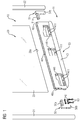
- the FIG. 1 shows a vehicle 10, which may be, for example, a rail vehicle.
- a device component 20 is mounted by means of a fastening device 30.
- the device component 20 in the embodiment according to FIG. 1 two parallel frame sections 21 and 22 and an intermediate separating part 23, which may be, for example, a glass pane.
- the separating part 23 is connected at the edge to the two frame sections 21 and 22.
- the vehicle floor 11 forms a first part of an arrangement in which the first part a second part in the form of the device component 20 is connected by means of the fastening device 30.
- the fastening device 30 comprises an extruded profile part 40 and two angle elements 50 and 51, which are preferably identical in construction and are connected to the extruded profile part 40, in particular screwed.
- fixing elements 60 which are preferably screws.
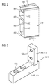
- the profile cross section of the extruded section 40 is closer in the FIG. 2 shown. It can be seen an outer plate 410, which rest on the vehicle floor 11 according to FIG. 1 serves. Parallel to the outer plate 410, a second plate 420 is arranged, which is connected to the outer plate 410 by two side walls 430 and 440. The two side walls 430 and 440 are preferably arranged parallel to one another. The two side walls 430 and 440, the outer plate 410 and the second plate 420 form a cross-sectionally closed lower extruded section 450 of the extruded section 40.
- the extruded section 450 extends in the extrusion direction S tubular with a polygonal and approximately rectangular cross-section.
- the lower extruded profile section 450 serves to receive the two angle elements 50 and 51 according to FIG. 1 ,
- FIG. 2 FIG. 4 also shows a third plate 460 which, together with the second plate 420 and the two side walls 430 and 440, forms a cross-sectionally closed, upper extruded profile section 470 of the extruded profile part 40.
- the upper extruded profile section 470 also extends in a tubular manner along the extrusion direction S of the extruded profile part 40.
- the two side walls 430 and 440 extend beyond the upper extruded section 470 and, together with the third plate 460, form a section 480, viewed in cross-section, which is U-shaped.
- the U-shaped portion 480 forms a receiving groove 481, into which a support portion 20a of the device component 20 according to FIG. 1 can be inserted for fixing on the extruded section 40.
- the support portion 20 a of the device component 20 is formed by a lower edge of the separator 23.
- components shown may be as follows:
- the angle element 50 is connected to the extruded section 40. This is done by a first portion 50a is inserted from the end face 40a in the lower extruded section 450 and then connected to the second plate 420, in particular screwed. The screwing of the first portion 50a takes place by means of the fixing elements 60.
- the fixing elements 60 are preferably screwed into threads which have been previously cut into the second plate 420.
- the angle member 51 Before or after the angle member 51 is inserted in a corresponding manner on the end face 40b in the lower extruded section 450, and it is the first portion 51a of the angle member 51 connected to the second plate 420, in particular screwed.
- the second portion 50b of the angle member 50 is connected to the frame portion 21, in particular screwed.
- the frame section 21 extends on the end face 40a of the extruded profile part 40 and past the angle part 50 in the direction of the vehicle floor 11.
- fixing elements 61 which may be, for example, screws.
- the fixing elements 61 are preferably screwed into threads which are present in the frame section 21.
- the separating part 23 of the device component 20 is inserted into the receiving groove 481 of the extruded profile part 40.
- the extruded section 40 Before or after the extruded section 40 is connected to the vehicle floor 11 of the vehicle 10, preferably screwed.
- holes 411 are provided in the outer plate 410, which are spaced along the extrusion direction S of the extruded section 40.
- recesses 441 are provided in the side wall 440, as shown in FIGS FIG. 1 is shown.
- corresponding recesses may also be provided in the side wall 430, but this is not absolutely necessary.
- the recess 441 which is provided in the region of the end face 40a of the extruded section 40, not only facilitates attachment of the extruded section 40 on the vehicle floor 11, but also connecting the first section 50a of the angled section 50 to the overlying second plate 420 of the Extruded section 40.
- this recess 441 also simplifies the Access to the fixing elements 61, which serve to connect the second portion 50 b of the angle part 50 with the frame portion 21.
- the recess 441 provided in the region of the end face 40b of the extruded profile part 40 correspondingly simplifies access to the holes 411 in this section of the extruded profile part 40 and furthermore connects the first section 51a of the angle element 51 to the second plate 420 of the extruded profile part 40 above and connecting the second portion 51b of the angle member 51 to the frame portion 22 of the device component 20.
- the device component 20 is connected to the vehicle floor 11 of the vehicle 10 by means of a plurality of assembly steps, the order of which is arbitrary.
- the extruded section 40 can be mounted on the vehicle floor 11 before the device component 20 or the angle elements 50 and 51 are mounted.
- the order is arbitrary, since the described embodiment of the extruded profile part 40 and the described embodiment of the angle elements 50 and 51 can always be used to access all fixing elements 60 and 61 independently of previous assembly steps.
- FIG. 3 shows the configuration of the two angle elements 50 and 51 again in another illustration. It can be seen the first portion 50a and 51a, which serves for connection to the second plate 420 of the extruded section 40 and this is equipped with holes 500a, through which the fixing elements 60 according to FIG. 1 can be passed.
- the fixing elements 60 are preferably in thread screwed, which are provided in the second plate 420 of the extruded section 40.
- the second section 50b or 51b which serves for connecting the extruded profile part 40 with the two frame sections 21 and 22 of the device component 20 and for this purpose is provided with holes 500b through which the fixing elements 61 according to FIG. 1 can be passed.
Landscapes
- Engineering & Computer Science (AREA)
- General Engineering & Computer Science (AREA)
- Mechanical Engineering (AREA)
- Architecture (AREA)
- Physics & Mathematics (AREA)
- Electromagnetism (AREA)
- Civil Engineering (AREA)
- Structural Engineering (AREA)
- Body Structure For Vehicles (AREA)
- Furniture Connections (AREA)
Abstract
Description
- Die Erfindung bezieht sich auf Anordnungen mit einem ersten Teil, einem zweiten Teil und einer Befestigungseinrichtung, die das erste und zweite Teil verbindet, sowie auf Fahrzeuge mit solchen Anordnungen.
- Bei Fahrzeugen werden Komponenten wie Gepäckregale, Glastrennwände, Raumteiler oder Türflügel heutzutage mit zusätzlichen Befestigungsflächen bzw. Anschraubflächen mit dem Fahrzeugboden verbunden. Diese zusätzlichen Bauteile benötigen zusätzlichen Bauraum und müssen teilweise in den Fußboden eingelassen und versiegelt werden, um das Erscheinungsbild des Fahrzeugs nicht negativ zu beeinflussen. Des Weiteren erzeugen die zusätzlichen Flächen und Verfestigungselemente neben dem Montageaufwand auch ein erhöhtes Gewicht.
- Der Erfindung liegt die Aufgabe zugrunde, für Anordnungen der eingangs angegebenen Art eine besonders einfach zu montierende, aber dennoch mechanisch sehr belastbare, Befestigungseinrichtung anzugeben.
- Diese Aufgabe wird erfindungsgemäß durch eine Anordnung mit den Merkmalen gemäß Patentanspruch 1 gelöst. Vorteilhafte Ausgestaltungen der erfindungsgemäßen Anordnung sind in Unteransprüchen angegeben.
- Danach ist erfindungsgemäß vorgesehen, dass die Befestigungseinrichtung ein Strangpressprofilteil und ein Winkelelement umfasst, das Strangpressprofilteil eine Außenplatte aufweist, die auf dem ersten Teil aufliegt und mit diesem verbunden ist, das Strangpressprofilteil eine zweite Platte aufweist, die parallel zur Außenplatte angeordnet ist und mit einem ersten Abschnitt des Winkelteils verbunden ist, und ein zweiter Abschnitt des Winkelteils, der zu dem ersten Abschnitt winklig angeordnet ist, mit dem zweiten Teil verbunden ist.
- Ein wesentlicher Vorteil der erfindungsgemäßen Anordnung ist darin zu sehen, dass es Strangpressprofilteile ermöglichen, durch entsprechende Formgebung den Einsatz standardisierter Winkelteile vorzusehen. Darüber hinaus ermöglichen es Strangpressprofilteile in vorteilhafter Weise, eine Befestigung zwischen dem ersten und zweiten Teil stets auch in der jeweiligen Hauptbelastungsrichtung zu gewährleisten.
- Bezüglich der Ausgestaltung des Strangpressprofilteils wird es mit Blick auf hohe mechanische Stabilität als vorteilhaft angesehen, wenn die Außenplatte und die zweite Platte durch zwei parallele Seitenwände verbunden sind, die gemeinsam mit der Außenplatte und der zweiten Platte einen im Querschnitt geschlossenen Strangpressprofilabschnitt bilden, der sich entlang der Strangpressprofilrichtung rohrförmig erstreckt, das Winkelteil in dem geschlossenen Strangpressprofilabschnitt angeordnet ist und zumindest eine der Seitenwände im Bereich des Winkelteils eine seitliche Ausnehmung aufweist, die einen seitlichen Zugang zum Winkelteil ermöglicht.
- Bei der letztgenannten Ausgestaltung ist es darüber hinaus vorteilhaft, wenn das Winkelteil in einem stirnseitigen Endabschnitt des geschlossenen Strangpressprofilabschnitts angeordnet ist und der zweite Abschnitt des Winkelteils eine stirnseitige Anschlussschnittstelle zu dem zweiten Teil bildet.
- Das Strangpressprofilteil besteht vorzugsweise aus Aluminium.
- Der erste und zweite Abschnitt des Winkelteils stehen vorzugsweise senkrecht aufeinander.
- Mit Blick auf eine feste Anbindung des Strangpressprofilteils am ersten Teil wird es als vorteilhaft angesehen, wenn das Strangpressprofilteil in der Außenplatte eine Vielzahl an in Strangpressrichtung beabstandeten Befestigungslöchern aufweist, die ein Befestigen, insbesondere Anschrauben, des Strangpressprofilteils, auf dem ersten Teil ermöglichen.
- Vorzugsweise weist zumindest eine der Seitenwände für jedes der in Strangpressrichtung beabstandeten Befestigungslöcher eine seitliche Ausnehmung auf, die einen seitlichen Zugang zum zugeordneten Befestigungsloch ermöglicht. Es können sich dabei mehrere Befestigungslöcher eine gemeinsame seitliche Ausnehmung teilen.
- Bezüglich der Anbindung des zweiten Teils wird es als vorteilhaft angesehen, wenn das Strangpressprofilteil einen im Querschnitt u-förmigen Abschnitt aufweist, in den ein Auflageabschnitt des zweiten Teils eingeschoben ist.
- Vorzugsweise weist das zweite Teil einen Rahmenabschnitt auf, der sich an der Stirnseite des Strangpressprofilteils und an dem Winkelteil vorbei in Richtung des ersten Teils erstreckt.
- Auch ist es mit Blick auf hohe mechanische Stabilität vorteilhaft, wenn der u-förmige Abschnitt des Strangpressprofilteils durch die beiden Seitenwände des Strangpressprofilteils und eine dritte Platte gebildet ist, die parallel zur zweiten Platte des Strangpressprofilteils angeordnet ist und gemeinsam mit dieser und den beiden Seitenwänden einen im Querschnitt geschlossenen Strangpressprofilabschnitt bilden, der sich entlang der Strangpressprofilrichtung rohrförmig erstreckt.
- Bei dem ersten Teil handelt es sich vorzugsweise um einen Fußboden, insbesondere einen Fahrzeugfußboden. Bei dem zweiten Teil handelt es sich vorzugsweise um eine Einrichtungskomponente, insbesondere eine Gepäckregalkomponente, eine Trennwand, einen Raumteiler oder einen Türflügel.
- Die Erfindung bezieht sich darüber hinaus auf eine Befestigungseinrichtung zum Verbinden eines ersten Teils mit einem zweiten Teil.
- Erfindungsgemäß ist bezüglich einer solchen Befestigungseinrichtung vorgesehen, das die Befestigungseinrichtung ein Strangpressprofilteil und ein Winkelelement umfasst, das mit dem zweiten Teil verbindbar, insbesondere verschraubbbar ist, und das Strangpressprofilteil eine Außenplatte zur Auflage auf dem ersten Teil und eine dazu parallele zweite Platte aufweist, die mit dem Winkelteil verbunden, insbesondere verschraubt, ist.
- Bezüglich der Vorteile der erfindungsgemäßen Befestigungseinrichtung sei auf die obigen Ausführungen im Zusammenhang mit der erfindungsgemäßen Anordnung verwiesen.
- Die Erfindung bezieht sich darüber hinaus auf ein Fahrzeug, insbesondere Schienenfahrzeug, bei dem zwei Teile mit einer Befestigungseinrichtung, insbesondere einer Befestigungseinrichtung wie sie oben beschrieben worden ist, verbunden sind.
- Vorteilhaft ist es bei einem solchen Fahrzeug, wenn das erste Teil ein Fußboden, insbesondere ein Fahrzeugfußboden ist, und das zweite Teil eine Einrichtungskomponente, insbesondere eine Gepäckregalkomponente, eine Trennwand, ein Raumteiler oder ein Türflügel, ist.
- Die Erfindung bezieht sich darüber hinaus auf ein Verfahren zum Verbinden eines ersten Teils mit einem zweiten Teil mittels einer Befestigungseinrichtung.
- Bezüglich eines solchen Verfahrens ist erfindungsgemäß vorgesehen, dass ein erster Abschnitt eines Winkelteils der Befestigungseinrichtung mit einem Strangpressprofilteil der Befestigungseinrichtung verbunden wird, und zwar mit einer zu einer Außenplatte des Strangpressprofilteils parallelen zweiten Platte, ein zweiter Abschnitt des Winkelteils, der zu dem ersten Abschnitt winklig angeordnet ist, mit dem zweiten Teil verbunden wird, und die Außenplatte des Strangpressprofilteils mit dem ersten Teil verbunden wird.
- Die Erfindung wird nachfolgend anhand von Ausführungsbeispielen näher erläutert; dabei zeigen beispielhaft:
- Figur 1
- ein Ausführungsbeispiel für ein Fahrzeug, auf dessen Fahrzeugfußboden eine Einrichtungskomponente montiert ist, wobei die
Figur 1 die Teile in einer Explosionsdarstellung zeigt, - Figur 2
- ein Ausführungsbeispiel für ein Strangpressprofilteil, das bei dem Fahrzeug gemäß
Figur 1 zur Befestigung der Einrichtungskomponente eingesetzt werden kann, näher im Detail und - Figur 3
- ein Ausführungsbeispiel für ein Winkelelement, das zur Befestigung der Einrichtungskomponente bei dem Fahrzeug gemäß
Figur 1 eingesetzt werden kann, näher im Detail. - In den Figuren werden der Übersicht halber für identische oder vergleichbare Komponenten stets dieselben Bezugszeichen verwendet.
- Die
Figur 1 zeigt ein Fahrzeug 10, bei dem es sich beispielsweise um ein Schienenfahrzeug handeln kann. Auf dem Fahrzeugboden 11 des Fahrzeugs 10 ist eine Einrichtungskomponente 20 mittels einer Befestigungseinrichtung 30 montiert. - Die Einrichtungskomponente 20 umfasst bei dem Ausführungsbeispiel gemäß
Figur 1 zwei parallele Rahmenabschnitte 21 und 22 sowie ein dazwischen liegendes Trennteil 23, bei dem es sich beispielsweise um eine Glasscheibe handeln kann. Das Trennteil 23 ist randseitig mit den beiden Rahmenabschnitten 21 und 22 verbunden. - Bei dem Fahrzeug 10 gemäß
Figur 1 bildet der Fahrzeugboden 11 ein erstes Teil einer Anordnung, bei der mit dem ersten Teil ein zweites Teil in Form der Einrichtungskomponente 20 mittels der Befestigungseinrichtung 30 verbunden ist. - Die Befestigungseinrichtung 30 umfasst ein Strangpressprofilteil 40 sowie zwei Winkelelemente 50 und 51, die vorzugsweise baugleich sind und mit dem Strangpressprofilteil 40 verbunden, insbesondere verschraubt sind. Zum Verbinden bzw. zum Verschrauben der beiden Winkelelemente 50 und 51 mit dem Strangpressprofilteil 40 dienen Fixierelemente 60, bei denen es sich vorzugsweise um Schrauben handelt.
- Der Profilquerschnitt des Strangpressprofilteils 40 ist näher in der
Figur 2 dargestellt. Man erkennt eine Außenplatte 410, die zur Auflage auf dem Fahrzeugboden 11 gemäßFigur 1 dient. Parallel zu der Außenplatte 410 ist eine zweite Platte 420 angeordnet, die mit der Außenplatte 410 durch zwei Seitenwände 430 und 440 verbunden ist. Die beiden Seitenwände 430 und 440 sind vorzugsweise parallel zueinander angeordnet. Die beiden Seitenwände 430 und 440, die Außenplatte 410 und die zweite Platte 420 bilden einen im Querschnitt geschlossenen unteren Strangpressprofilabschnitt 450 des Strangpressprofilteils 40. Der Strangpressprofilabschnitt 450 erstreckt sich in Strangpressrichtung S rohrförmig mit einem eckigen und näherungsweise rechteckigen Querschnitt. - Wie weiter unten noch näher erläutert werden wird, dient der untere Strangpressprofilabschnitt 450 zur Aufnahme der beiden Winkelelemente 50 und 51 gemäß
Figur 1 . - Die
Figur 2 zeigt darüber hinaus eine dritte Platte 460, die gemeinsam mit der zweiten Platte 420 sowie den beiden Seitenwänden 430 und 440 einen im Querschnitt geschlossenen, oberen Strangpressprofilabschnitt 470 des Strangpressprofilteils 40 bildet. Auch der obere Strangpressprofilabschnitt 470 erstreckt sich rohrförmig entlang der Strangpressrichtung S des Strangpressprofilteils 40. - In der
Figur 2 lässt sich außerdem erkennen, dass sich die beiden Seitenwände 430 und 440 über den oberen Strangpressprofilabschnitt 470 hinauserstrecken und gemeinsam mit der dritten Platte 460 einen - im Querschnitt betrachtet - u-förmigen Abschnitt 480 bilden. Der u-förmige Abschnitt 480 bildet eine Aufnahmerille 481, in die ein Auflageabschnitt 20a der Einrichtungskomponente 20 gemäßFigur 1 zur Fixierung auf dem Strangpressprofilteil 40 eingeschoben werden kann. Bei dem Ausführungsbeispiel gemäßFigur 1 wird der Auflageabschnitt 20a der Einrichtungskomponente 20 durch einen unteren Rand des Trennteils 23 gebildet. - Die Montage der in der
Figur 1 dargestellten Komponenten kann beispielsweise wie folgt erfolgen: - In einem Arbeitsschritt wird das Winkelelement 50 mit dem Strangpressprofilteil 40 verbunden. Dies erfolgt, indem ein erster Abschnitt 50a von der Stirnseite 40a in den unteren Strangpressprofilabschnitt 450 eingeschoben wird und anschließend mit der zweiten Platte 420 verbunden, insbesondere verschraubt wird. Das Verschrauben des ersten Abschnitts 50a erfolgt mittels der Fixierelemente 60. Die Fixierelemente 60 werden bevorzugt in Gewinde eingeschraubt, die zuvor in die zweite Platte 420 eingeschnitten worden sind.
- Davor oder danach wird das Winkelelement 51 in entsprechender Weise an der Stirnseite 40b in den unteren Strangpressprofilabschnitt 450 eingeschoben, und es wird der erste Abschnitt 51a des Winkelelements 51 mit der zweiten Platte 420 verbunden, insbesondere verschraubt.
- Davor oder danach wird der zweite Abschnitt 50b des Winkelelements 50 mit dem Rahmenabschnitt 21 verbunden, insbesondere verschraubt. Der Rahmenabschnitt 21 erstreckt sich zu diesem Zwecke an der Stirnseite 40a des Strangpressprofilteils 40 und an dem Winkelteil 50 vorbei in Richtung des Fahrzeugbodens 11. Zur Verbindung zwischen dem Rahmenabschnitt 21 und dem zweiten Abschnitt 50b des Winkelelements 50 dienen Fixierelemente 61, bei denen es sich beispielsweise um Schrauben handeln kann. Die Fixierelemente 61 werden bevorzugt in Gewinde eingeschraubt, die in dem Rahmenabschnitt 21 vorhanden sind.
- In entsprechender Weise wird davor oder danach der zweite Abschnitt 51b des Winkelelements 51 mit dem Rahmenabschnitt 22 der Einrichtungskomponente 20 verbunden, insbesondere verschraubt.
- Wie bereits erwähnt, wird das Trennteil 23 der Einrichtungskomponente 20 in die Aufnahmerille 481 des Strangpressprofilteils 40 eingeschoben. Zur Erhöhung der Stabilität kann es von Vorteil sein, den Auflageabschnitt 20a der Einrichtungskomponente 20 mit der Aufnahmerille 481 des Strangpressprofilteils 40 zu verkleben.
- Davor oder danach wird das Strangpressprofilteil 40 mit dem Fahrzeugboden 11 des Fahrzeugs 10 verbunden, vorzugsweise verschraubt. Zur Verbindung des Strangpressprofilteils 40 sind in der Außenplatte 410 Löcher 411 vorgesehen, die entlang der Strangpressrichtung S des Strangpressprofilteils 40 beabstandet sind.
- Um eine Zugänglichkeit zu den Löchern 411 zu vereinfachen oder zu gewährleisten, sind (vorzugsweise gefräste) Ausnehmungen 441 in der Seitenwand 440 vorgesehen, wie dies in der
Figur 1 gezeigt ist. Zusätzlich können entsprechende Ausnehmungen auch in der Seitenwand 430 vorgesehen sein, jedoch ist dies nicht zwingend nötig. - Die Ausnehmung 441, die im Bereich der Stirnseite 40a des Strangpressprofilteils 40 vorgesehen ist, vereinfacht nicht nur eine Befestigung des Strangpressprofilteils 40 auf dem Fahrzeugboden 11, sondern darüber hinaus auch ein Verbinden des ersten Abschnitts 50a des Winkelteils 50 an der darüber befindlichen zweiten Platte 420 des Strangpressprofilteils 40. Darüber hinaus vereinfacht diese Ausnehmung 441 auch den Zugang zu den Fixierelementen 61, die zum Verbinden des zweiten Abschnitts 50b des Winkelteils 50 mit dem Rahmenabschnitt 21 dienen.
- Die im Bereich der Stirnseite 40b des Strangpressprofilteils 40 vorgesehene Ausnehmung 441 vereinfacht in entsprechender Weise einen Zugang zu den Löchern 411 in diesem Abschnitt des Strangpressprofilteils 40 sowie darüber hinaus ein Verbinden des ersten Abschnitts 51a des Winkelelements 51 mit der darüber befindlichen zweiten Platte 420 des Strangpressprofilteils 40 sowie ein Verbinden des zweiten Abschnitts 51b des Winkelelements 51 mit dem Rahmenabschnitt 22 der Einrichtungskomponente 20.
- Zusammengefasst wird die Einrichtungskomponente 20 auf dem Fahrzeugboden 11 des Fahrzeugs 10 mittels mehrerer Montageschritte verbunden, deren Reihenfolge beliebig ist. So kann das Strangpressprofilteil 40 auf dem Fahrzeugboden 11 montiert werden, bevor die Einrichtungskomponente 20 oder die Winkelelemente 50 und 51 montiert werden. Alternativ ist es möglich, zunächst die Einrichtungskomponente 20 mittels der Winkelelemente 50 und 51 an dem Strangpressprofilteil 40 zu befestigen, bevor das Strangpressprofilteil 40 auf dem Fahrzeugboden 11 montiert wird. Die Reihenfolge ist beliebig, da durch die beschriebene Ausgestaltung des Strangpressprofilteils 40 und die beschriebene Ausgestaltung der Winkelelemente 50 und 51 auf alle Fixierelemente 60 und 61 unabhängig von vorangegangenen Montageschritten stets zugegriffen werden kann.
- Die
Figur 3 zeigt die Ausgestaltung der beiden Winkelelemente 50 und 51 nochmals in einer anderen Darstellung. Man erkennt den ersten Abschnitt 50a bzw. 51a, der zur Verbindung mit der zweiten Platte 420 des Strangpressprofilteils 40 dient und hierzu mit Löchern 500a ausgestattet ist, durch die die Fixierelemente 60 gemäßFigur 1 hindurchgeführt werden können. Die Fixierelemente 60 werden vorzugsweise in Gewinde eingeschraubt, die in der zweiten Platte 420 des Strangpressprofilteils 40 vorgesehen sind. - Darüber hinaus erkennt man den zweiten Abschnitt 50b bzw. 51b, der zum Verbinden des Strangpressprofilteils 40 mit den beiden Rahmenabschnitten 21 und 22 der Einrichtungskomponente 20 dient und hierzu mit Löchern 500b ausgestattet ist, durch die die Fixierelemente 61 gemäß
Figur 1 hindurchgeführt werden können. - Obwohl die Erfindung im Detail durch bevorzugte Ausführungsbeispiele näher illustriert und beschrieben wurde, so ist die Erfindung nicht durch die offenbarten Beispiele eingeschränkt und andere Variationen können vom Fachmann hieraus abgeleitet werden, ohne den Schutzumfang der Erfindung zu verlassen.
Claims (12)
- Anordnung mit einem ersten Teil, einem zweiten Teil und einer Befestigungseinrichtung (30), die das erste und das zweite Teil verbindet,
dadurch gekennzeichnet, dass- die Befestigungseinrichtung (30) ein Strangpressprofilteil (40) und ein Winkelelement (50, 51) umfasst,- das Strangpressprofilteil (40) eine Außenplatte (410) aufweist, die auf dem ersten Teil aufliegt und mit diesem verbunden ist,- das Strangpressprofilteil (40) eine zweite Platte (420) aufweist, die parallel zur Außenplatte (410) angeordnet ist und mit einem ersten Abschnitt (50a, 51a) des Winkelteils (50, 51) verbunden ist, und- ein zweiter Abschnitt (50b, 51b) des Winkelteils (50, 51), der zu dem ersten Abschnitt (50a, 51a) winklig angeordnet ist, mit dem zweiten Teil verbunden ist. - Anordnung nach Anspruch 1,
dadurch gekennzeichnet, dass- die Außenplatte (410) und die zweite Platte (420) durch zwei parallele Seitenwände (430, 440) verbunden sind, die gemeinsam mit der Außenplatte (410) und der zweiten Platte (420) einen im Querschnitt geschlossenen Strangpressprofilabschnitt (450) bilden, der sich entlang der Strangpressrichtung (S) rohrförmig erstreckt,- das Winkelteil (50, 51) in dem geschlossenen Strangpressprofilabschnitt (450) angeordnet ist und- zumindest eine der Seitenwände (430, 440) im Bereich des Winkelteils (50, 51) eine seitliche Ausnehmung (441) aufweist, die einen seitlichen Zugang zum Winkelteil (50, 51) ermöglicht. - Anordnung nach Anspruch 2,
dadurch gekennzeichnet, dass- das Winkelteil (50, 51) in einem stirnseitigen Endabschnitt des geschlossenen Strangpressprofilabschnitts (450) angeordnet ist und- der zweite Abschnitt (50b, 51b) des Winkelteils (50, 51) eine stirnseitige Anschlussschnittstelle zu dem zweiten Teil bildet. - Anordnung nach einem der voranstehenden Ansprüche,
dadurch gekennzeichnet, dass
das Strangpressprofilteil (40) in der Außenplatte (410) eine Vielzahl an in Strangpressrichtung (S) beabstandeten Befestigungslöchern (411) aufweist, die ein Befestigen, insbesondere Anschrauben, des Strangpressprofilteils (40), auf dem ersten Teil ermöglichen. - Anordnung nach Anspruch 4,
dadurch gekennzeichnet, dass
zumindest eine der Seitenwände (430, 440) für jedes der in Strangpressrichtung (S) beabstandeten Befestigungslöcher (411) eine seitliche Ausnehmung (441) aufweist, die einen seitlichen Zugang zum zugeordneten Befestigungsloch (411) ermöglicht. - Anordnung nach einem der voranstehenden Ansprüche,
dadurch gekennzeichnet, dass
das Strangpressprofilteil (40) einen im Querschnitt u-förmigen Abschnitt (480) aufweist, in den ein Auflageabschnitt (20a) des zweiten Teils eingeschoben ist. - Anordnung nach einem der voranstehenden Ansprüche,
dadurch gekennzeichnet, dass
das zweite Teil einen Rahmenabschnitt (21, 22) aufweist, der sich an der Stirnseite (40a, 40b) des Strangpressprofilteils (40) und an dem Winkelteil (50, 51) vorbei in Richtung des ersten Teils erstreckt. - Anordnung nach einem der voranstehenden Ansprüche,
dadurch gekennzeichnet, dass
der u-förmige Abschnitt (480) des Strangpressprofilteils (40) durch die beiden Seitenwände (430, 440) des Strangpressprofilteils (40) und eine dritte Platte (460) gebildet ist, die parallel zur zweiten Platte (420) des Strangpressprofilteils (40) angeordnet ist und gemeinsam mit dieser und den beiden Seitenwänden (430, 440) einen im Querschnitt geschlossenen Strangpressprofilabschnitt (470) bilden, der sich entlang der Strangpressrichtung (S) rohrförmig erstreckt. - Anordnung nach einem der voranstehenden Ansprüche,
dadurch gekennzeichnet, dass- das erste Teil ein Fußboden, insbesondere ein Fahrzeugfußboden (11) ist, und- das zweite Teil eine Einrichtungskomponente (20), insbesondere eine Gepäckregalkomponente, eine Trennwand, ein Raumteiler oder ein Türflügel, ist. - Befestigungseinrichtung (30) zum Verbinden eines ersten Teiles mit einem zweiten Teil,
dadurch gekennzeichnet, dass- die Befestigungseinrichtung (30) ein Strangpressprofilteil (40) und ein Winkelelement (50, 51) umfasst, das mit dem zweiten Teil verbindbar, insbesondere verschraubbbar ist, und- das Strangpressprofilteil (40) eine Außenplatte (410) zur Auflage auf dem ersten Teil und eine dazu parallele zweite Platte (420) aufweist, die mit dem Winkelteil (50, 51) verbunden, insbesondere verschraubt, ist. - Fahrzeug, insbesondere Schienenfahrzeug,
dadurch gekennzeichnet, dass
das Fahrzeug eine Anordnung nach einem der voranstehenden Ansprüche 1 bis 9 oder eine Befestigungseinrichtung (30) nach Anspruch 10 aufweist. - Verfahren zum Verbinden eines ersten Teils mit einem zweiten Teil mittels einer Befestigungseinrichtung (30),
dadurch gekennzeichnet, dass- ein erster Abschnitt (50a, 51a) eines Winkelteils (50, 51) der Befestigungseinrichtung (30) mit einem Strangpressprofilteil (40) der Befestigungseinrichtung (30) verbunden wird, und zwar mit einer zu einer Außenplatte (410) des Strangpressprofilteils (40) parallelen zweiten Platte (420),- ein zweiter Abschnitt (50b, 51b) des Winkelteils (50, 51), der zu dem ersten Abschnitt (50a, 51a) winklig angeordnet ist, mit dem zweiten Teil verbunden wird, und- die Außenplatte (410) des Strangpressprofilteils (40) mit dem ersten Teil verbunden wird.
Applications Claiming Priority (1)
| Application Number | Priority Date | Filing Date | Title |
|---|---|---|---|
| DE102015204144.1A DE102015204144A1 (de) | 2015-03-09 | 2015-03-09 | Anordnung mit einer Befestigungseinrichtung |
Publications (2)
| Publication Number | Publication Date |
|---|---|
| EP3067496A1 true EP3067496A1 (de) | 2016-09-14 |
| EP3067496B1 EP3067496B1 (de) | 2020-08-26 |
Family
ID=55453034
Family Applications (1)
| Application Number | Title | Priority Date | Filing Date |
|---|---|---|---|
| EP16157072.6A Active EP3067496B1 (de) | 2015-03-09 | 2016-02-24 | Anordnung mit einer befestigungseinrichtung |
Country Status (3)
| Country | Link |
|---|---|
| EP (1) | EP3067496B1 (de) |
| DE (1) | DE102015204144A1 (de) |
| ES (1) | ES2833026T3 (de) |
Citations (2)
| Publication number | Priority date | Publication date | Assignee | Title |
|---|---|---|---|---|
| FR2667490A1 (fr) * | 1990-10-04 | 1992-04-10 | Cherel Alain | Elements de structure pour l'amenagement d'espaces de rangement. |
| EP1916372A2 (de) * | 2006-10-23 | 2008-04-30 | Hawa Ag | Vorrichtung zum Halten von Platten und Trennelement |
Family Cites Families (10)
| Publication number | Priority date | Publication date | Assignee | Title |
|---|---|---|---|---|
| CH682252A5 (en) * | 1990-10-30 | 1993-08-13 | Alusuisse Lonza Services Ag | Corner connection of two profiles with C=profile attachments - has attachments with two arms at free ends of which are counterpoised fillets with one profile having longitudinal grooves on its outer and inner sides |
| DE9102254U1 (de) * | 1991-02-26 | 1991-05-16 | Wallau, Helmut, 5464 Buchholz | Winkelelement |
| DE9200645U1 (de) * | 1992-01-21 | 1992-04-16 | Festo KG, 7300 Esslingen | Profilteil |
| DE59504612D1 (de) * | 1994-07-25 | 1999-02-04 | Alusuisse Lonza Services Ag | Verbindungselement |
| US6722811B2 (en) * | 2002-02-20 | 2004-04-20 | Blanking Systems, Inc. | Lower frame assembly for blanking tool |
| DE10210812B4 (de) * | 2002-03-12 | 2005-06-16 | Dorma Gmbh + Co. Kg | Trag- und Führungseinrichtung zum Halten von ortsveränderlichen, hängend gelagerten Tür- oder Wandelementen |
| US20060182492A1 (en) * | 2005-02-01 | 2006-08-17 | Adam's Specialty Products, Llc | Draw-wedge fasteners |
| JP2007263184A (ja) * | 2006-03-28 | 2007-10-11 | Showa Aircraft Ind Co Ltd | ジョイント用のインサート材 |
| DE202009007517U1 (de) * | 2009-05-20 | 2009-12-10 | Trienergy Gmbh | Ständer für rechteckige Solarmodule |
| DE202012010973U1 (de) * | 2012-06-12 | 2012-11-27 | Altec Solartechnik Ag | Profilschiene für Unterkonstruktionen sowie Befestigungselement hierfür |
-
2015
- 2015-03-09 DE DE102015204144.1A patent/DE102015204144A1/de not_active Ceased
-
2016
- 2016-02-24 ES ES16157072T patent/ES2833026T3/es active Active
- 2016-02-24 EP EP16157072.6A patent/EP3067496B1/de active Active
Patent Citations (2)
| Publication number | Priority date | Publication date | Assignee | Title |
|---|---|---|---|---|
| FR2667490A1 (fr) * | 1990-10-04 | 1992-04-10 | Cherel Alain | Elements de structure pour l'amenagement d'espaces de rangement. |
| EP1916372A2 (de) * | 2006-10-23 | 2008-04-30 | Hawa Ag | Vorrichtung zum Halten von Platten und Trennelement |
Also Published As
| Publication number | Publication date |
|---|---|
| DE102015204144A1 (de) | 2016-09-15 |
| EP3067496B1 (de) | 2020-08-26 |
| ES2833026T3 (es) | 2021-06-14 |
Similar Documents
| Publication | Publication Date | Title |
|---|---|---|
| EP3001931B1 (de) | Blendenprofilabdeckvorrichtung | |
| DE102012206288A1 (de) | Verkleidung einer Innenseite einer Seitenwand eines Schienenfahrzeugs | |
| EP2508407A1 (de) | Gerüst, insbesondere für elektrische Einrichtungen in einem Schienenfahrzeug, und Verfahren zur Herstellung des Gerüsts | |
| DE102016115404A1 (de) | System zur Festlegung wenigstens eines Wandverkleidungsteils | |
| DE102014000839B4 (de) | Messe-Fertigbausystem mit Fertig-Rahmenmodulen | |
| EP2868544B1 (de) | Befestigungsvorrichtung für ein Übergangsprofil in einem Schienenfahrzeug, Bausatz für eine Befestigungsvorrichtung und Verfahren zum Befestigen eines Übergangsprofils | |
| DE102011112074A1 (de) | Möbeleinheit | |
| DE202015005659U1 (de) | Profilsystem zur Bildung eines Untertragrahmens für die Aufnahme von Bodendielen und Profilschiene | |
| DE102014202783B4 (de) | Flugzeugkabinenanordnung | |
| DE202018105796U1 (de) | Trockenbau-Tragrahmen für eine Schiebetür | |
| EP3140174B1 (de) | Fahrzeug, insbesondere schienenfahrzeug, mit einer montageschiene | |
| EP1798186B1 (de) | Aufzugskabine und Verfahren zum Montieren von Wandelementen einer Kabinenwand | |
| DE102012110247A1 (de) | Schaltschrank mit verbesserter Möglichkeit zur Aneinanderreihung | |
| EP3342305A1 (de) | Masthalter sowie verfahren zum montieren eines masthalters | |
| DE102016115410A1 (de) | Sytem zur Festlegung wenigstens eines Wandverkleidungsteils | |
| EP3067496B1 (de) | Anordnung mit einer befestigungseinrichtung | |
| DE102010018368A1 (de) | Trennwandsystem für den Innenausbau | |
| EP4114150A1 (de) | Erweiterungsbausatz | |
| EP2084990A1 (de) | Fachbodenträger und Regalsystem | |
| EP3130716B1 (de) | Wandbauplatte und wandbausystem für den messebau | |
| AT518135B1 (de) | Schubkasten für einen Spülenunterschrank | |
| EP4424210B1 (de) | Regaleinschub | |
| DE29713191U1 (de) | Schiebeflügel mit einem aus Metallprofilen hergestellten Rahmen | |
| EP3685705A1 (de) | Profil zum aufbau von betriebseinrichtungen und betriebseinrichtung | |
| DE19933252B4 (de) | Trennwandsystem |
Legal Events
| Date | Code | Title | Description |
|---|---|---|---|
| PUAI | Public reference made under article 153(3) epc to a published international application that has entered the european phase |
Free format text: ORIGINAL CODE: 0009012 |
|
| AK | Designated contracting states |
Kind code of ref document: A1 Designated state(s): AL AT BE BG CH CY CZ DE DK EE ES FI FR GB GR HR HU IE IS IT LI LT LU LV MC MK MT NL NO PL PT RO RS SE SI SK SM TR |
|
| AX | Request for extension of the european patent |
Extension state: BA ME |
|
| STAA | Information on the status of an ep patent application or granted ep patent |
Free format text: STATUS: REQUEST FOR EXAMINATION WAS MADE |
|
| 17P | Request for examination filed |
Effective date: 20170313 |
|
| RBV | Designated contracting states (corrected) |
Designated state(s): AL AT BE BG CH CY CZ DE DK EE ES FI FR GB GR HR HU IE IS IT LI LT LU LV MC MK MT NL NO PL PT RO RS SE SI SK SM TR |
|
| RAP1 | Party data changed (applicant data changed or rights of an application transferred) |
Owner name: SIEMENS AKTIENGESELLSCHAFT |
|
| RAP1 | Party data changed (applicant data changed or rights of an application transferred) |
Owner name: SIEMENS MOBILITY GMBH |
|
| STAA | Information on the status of an ep patent application or granted ep patent |
Free format text: STATUS: EXAMINATION IS IN PROGRESS |
|
| 17Q | First examination report despatched |
Effective date: 20190717 |
|
| GRAP | Despatch of communication of intention to grant a patent |
Free format text: ORIGINAL CODE: EPIDOSNIGR1 |
|
| STAA | Information on the status of an ep patent application or granted ep patent |
Free format text: STATUS: GRANT OF PATENT IS INTENDED |
|
| INTG | Intention to grant announced |
Effective date: 20200430 |
|
| GRAS | Grant fee paid |
Free format text: ORIGINAL CODE: EPIDOSNIGR3 |
|
| GRAA | (expected) grant |
Free format text: ORIGINAL CODE: 0009210 |
|
| STAA | Information on the status of an ep patent application or granted ep patent |
Free format text: STATUS: THE PATENT HAS BEEN GRANTED |
|
| AK | Designated contracting states |
Kind code of ref document: B1 Designated state(s): AL AT BE BG CH CY CZ DE DK EE ES FI FR GB GR HR HU IE IS IT LI LT LU LV MC MK MT NL NO PL PT RO RS SE SI SK SM TR |
|
| REG | Reference to a national code |
Ref country code: GB Ref legal event code: FG4D Free format text: NOT ENGLISH |
|
| REG | Reference to a national code |
Ref country code: CH Ref legal event code: EP |
|
| REG | Reference to a national code |
Ref country code: AT Ref legal event code: REF Ref document number: 1306523 Country of ref document: AT Kind code of ref document: T Effective date: 20200915 |
|
| REG | Reference to a national code |
Ref country code: IE Ref legal event code: FG4D Free format text: LANGUAGE OF EP DOCUMENT: GERMAN |
|
| REG | Reference to a national code |
Ref country code: DE Ref legal event code: R096 Ref document number: 502016010923 Country of ref document: DE |
|
| REG | Reference to a national code |
Ref country code: CH Ref legal event code: NV Representative=s name: SIEMENS SCHWEIZ AG, CH |
|
| REG | Reference to a national code |
Ref country code: LT Ref legal event code: MG4D |
|
| PG25 | Lapsed in a contracting state [announced via postgrant information from national office to epo] |
Ref country code: FI Free format text: LAPSE BECAUSE OF FAILURE TO SUBMIT A TRANSLATION OF THE DESCRIPTION OR TO PAY THE FEE WITHIN THE PRESCRIBED TIME-LIMIT Effective date: 20200826 Ref country code: GR Free format text: LAPSE BECAUSE OF FAILURE TO SUBMIT A TRANSLATION OF THE DESCRIPTION OR TO PAY THE FEE WITHIN THE PRESCRIBED TIME-LIMIT Effective date: 20201127 Ref country code: NO Free format text: LAPSE BECAUSE OF FAILURE TO SUBMIT A TRANSLATION OF THE DESCRIPTION OR TO PAY THE FEE WITHIN THE PRESCRIBED TIME-LIMIT Effective date: 20201126 Ref country code: SE Free format text: LAPSE BECAUSE OF FAILURE TO SUBMIT A TRANSLATION OF THE DESCRIPTION OR TO PAY THE FEE WITHIN THE PRESCRIBED TIME-LIMIT Effective date: 20200826 Ref country code: HR Free format text: LAPSE BECAUSE OF FAILURE TO SUBMIT A TRANSLATION OF THE DESCRIPTION OR TO PAY THE FEE WITHIN THE PRESCRIBED TIME-LIMIT Effective date: 20200826 Ref country code: LT Free format text: LAPSE BECAUSE OF FAILURE TO SUBMIT A TRANSLATION OF THE DESCRIPTION OR TO PAY THE FEE WITHIN THE PRESCRIBED TIME-LIMIT Effective date: 20200826 Ref country code: BG Free format text: LAPSE BECAUSE OF FAILURE TO SUBMIT A TRANSLATION OF THE DESCRIPTION OR TO PAY THE FEE WITHIN THE PRESCRIBED TIME-LIMIT Effective date: 20201126 Ref country code: PT Free format text: LAPSE BECAUSE OF FAILURE TO SUBMIT A TRANSLATION OF THE DESCRIPTION OR TO PAY THE FEE WITHIN THE PRESCRIBED TIME-LIMIT Effective date: 20201228 |
|
| REG | Reference to a national code |
Ref country code: NL Ref legal event code: MP Effective date: 20200826 |
|
| PG25 | Lapsed in a contracting state [announced via postgrant information from national office to epo] |
Ref country code: IS Free format text: LAPSE BECAUSE OF FAILURE TO SUBMIT A TRANSLATION OF THE DESCRIPTION OR TO PAY THE FEE WITHIN THE PRESCRIBED TIME-LIMIT Effective date: 20201226 Ref country code: LV Free format text: LAPSE BECAUSE OF FAILURE TO SUBMIT A TRANSLATION OF THE DESCRIPTION OR TO PAY THE FEE WITHIN THE PRESCRIBED TIME-LIMIT Effective date: 20200826 Ref country code: NL Free format text: LAPSE BECAUSE OF FAILURE TO SUBMIT A TRANSLATION OF THE DESCRIPTION OR TO PAY THE FEE WITHIN THE PRESCRIBED TIME-LIMIT Effective date: 20200826 Ref country code: PL Free format text: LAPSE BECAUSE OF FAILURE TO SUBMIT A TRANSLATION OF THE DESCRIPTION OR TO PAY THE FEE WITHIN THE PRESCRIBED TIME-LIMIT Effective date: 20200826 Ref country code: RS Free format text: LAPSE BECAUSE OF FAILURE TO SUBMIT A TRANSLATION OF THE DESCRIPTION OR TO PAY THE FEE WITHIN THE PRESCRIBED TIME-LIMIT Effective date: 20200826 |
|
| PG25 | Lapsed in a contracting state [announced via postgrant information from national office to epo] |
Ref country code: EE Free format text: LAPSE BECAUSE OF FAILURE TO SUBMIT A TRANSLATION OF THE DESCRIPTION OR TO PAY THE FEE WITHIN THE PRESCRIBED TIME-LIMIT Effective date: 20200826 Ref country code: RO Free format text: LAPSE BECAUSE OF FAILURE TO SUBMIT A TRANSLATION OF THE DESCRIPTION OR TO PAY THE FEE WITHIN THE PRESCRIBED TIME-LIMIT Effective date: 20200826 Ref country code: SM Free format text: LAPSE BECAUSE OF FAILURE TO SUBMIT A TRANSLATION OF THE DESCRIPTION OR TO PAY THE FEE WITHIN THE PRESCRIBED TIME-LIMIT Effective date: 20200826 Ref country code: DK Free format text: LAPSE BECAUSE OF FAILURE TO SUBMIT A TRANSLATION OF THE DESCRIPTION OR TO PAY THE FEE WITHIN THE PRESCRIBED TIME-LIMIT Effective date: 20200826 Ref country code: CZ Free format text: LAPSE BECAUSE OF FAILURE TO SUBMIT A TRANSLATION OF THE DESCRIPTION OR TO PAY THE FEE WITHIN THE PRESCRIBED TIME-LIMIT Effective date: 20200826 |
|
| REG | Reference to a national code |
Ref country code: DE Ref legal event code: R097 Ref document number: 502016010923 Country of ref document: DE |
|
| PG25 | Lapsed in a contracting state [announced via postgrant information from national office to epo] |
Ref country code: AL Free format text: LAPSE BECAUSE OF FAILURE TO SUBMIT A TRANSLATION OF THE DESCRIPTION OR TO PAY THE FEE WITHIN THE PRESCRIBED TIME-LIMIT Effective date: 20200826 |
|
| REG | Reference to a national code |
Ref country code: ES Ref legal event code: FG2A Ref document number: 2833026 Country of ref document: ES Kind code of ref document: T3 Effective date: 20210614 |
|
| PG25 | Lapsed in a contracting state [announced via postgrant information from national office to epo] |
Ref country code: SK Free format text: LAPSE BECAUSE OF FAILURE TO SUBMIT A TRANSLATION OF THE DESCRIPTION OR TO PAY THE FEE WITHIN THE PRESCRIBED TIME-LIMIT Effective date: 20200826 |
|
| PLBE | No opposition filed within time limit |
Free format text: ORIGINAL CODE: 0009261 |
|
| STAA | Information on the status of an ep patent application or granted ep patent |
Free format text: STATUS: NO OPPOSITION FILED WITHIN TIME LIMIT |
|
| 26N | No opposition filed |
Effective date: 20210527 |
|
| PG25 | Lapsed in a contracting state [announced via postgrant information from national office to epo] |
Ref country code: SI Free format text: LAPSE BECAUSE OF FAILURE TO SUBMIT A TRANSLATION OF THE DESCRIPTION OR TO PAY THE FEE WITHIN THE PRESCRIBED TIME-LIMIT Effective date: 20200826 |
|
| PG25 | Lapsed in a contracting state [announced via postgrant information from national office to epo] |
Ref country code: MC Free format text: LAPSE BECAUSE OF FAILURE TO SUBMIT A TRANSLATION OF THE DESCRIPTION OR TO PAY THE FEE WITHIN THE PRESCRIBED TIME-LIMIT Effective date: 20200826 |
|
| PG25 | Lapsed in a contracting state [announced via postgrant information from national office to epo] |
Ref country code: LU Free format text: LAPSE BECAUSE OF NON-PAYMENT OF DUE FEES Effective date: 20210224 |
|
| PG25 | Lapsed in a contracting state [announced via postgrant information from national office to epo] |
Ref country code: IE Free format text: LAPSE BECAUSE OF NON-PAYMENT OF DUE FEES Effective date: 20210224 |
|
| PG25 | Lapsed in a contracting state [announced via postgrant information from national office to epo] |
Ref country code: HU Free format text: LAPSE BECAUSE OF FAILURE TO SUBMIT A TRANSLATION OF THE DESCRIPTION OR TO PAY THE FEE WITHIN THE PRESCRIBED TIME-LIMIT; INVALID AB INITIO Effective date: 20160224 |
|
| PG25 | Lapsed in a contracting state [announced via postgrant information from national office to epo] |
Ref country code: CY Free format text: LAPSE BECAUSE OF FAILURE TO SUBMIT A TRANSLATION OF THE DESCRIPTION OR TO PAY THE FEE WITHIN THE PRESCRIBED TIME-LIMIT Effective date: 20200826 |
|
| PG25 | Lapsed in a contracting state [announced via postgrant information from national office to epo] |
Ref country code: MK Free format text: LAPSE BECAUSE OF FAILURE TO SUBMIT A TRANSLATION OF THE DESCRIPTION OR TO PAY THE FEE WITHIN THE PRESCRIBED TIME-LIMIT Effective date: 20200826 |
|
| PG25 | Lapsed in a contracting state [announced via postgrant information from national office to epo] |
Ref country code: MT Free format text: LAPSE BECAUSE OF FAILURE TO SUBMIT A TRANSLATION OF THE DESCRIPTION OR TO PAY THE FEE WITHIN THE PRESCRIBED TIME-LIMIT Effective date: 20200826 |
|
| PGFP | Annual fee paid to national office [announced via postgrant information from national office to epo] |
Ref country code: AT Payment date: 20250110 Year of fee payment: 10 Ref country code: BE Payment date: 20250218 Year of fee payment: 10 |
|
| PGFP | Annual fee paid to national office [announced via postgrant information from national office to epo] |
Ref country code: TR Payment date: 20250217 Year of fee payment: 10 |
|
| PGFP | Annual fee paid to national office [announced via postgrant information from national office to epo] |
Ref country code: DE Payment date: 20250417 Year of fee payment: 10 |
|
| PGFP | Annual fee paid to national office [announced via postgrant information from national office to epo] |
Ref country code: ES Payment date: 20250520 Year of fee payment: 10 |
|
| PGFP | Annual fee paid to national office [announced via postgrant information from national office to epo] |
Ref country code: CH Payment date: 20250512 Year of fee payment: 10 |
|
| REG | Reference to a national code |
Ref country code: DE Ref legal event code: R081 Ref document number: 502016010923 Country of ref document: DE Owner name: SIEMENS MOBILITY GMBH, DE Free format text: FORMER OWNER: SIEMENS AKTIENGESELLSCHAFT, 80333 MUENCHEN, DE |
|
| PGFP | Annual fee paid to national office [announced via postgrant information from national office to epo] |
Ref country code: GB Payment date: 20260310 Year of fee payment: 11 |
|
| PGFP | Annual fee paid to national office [announced via postgrant information from national office to epo] |
Ref country code: IT Payment date: 20260225 Year of fee payment: 11 |
|
| PGFP | Annual fee paid to national office [announced via postgrant information from national office to epo] |
Ref country code: FR Payment date: 20260213 Year of fee payment: 11 |
|
| REG | Reference to a national code |
Ref country code: CH Ref legal event code: U11 Free format text: ST27 STATUS EVENT CODE: U-0-0-U10-U11 (AS PROVIDED BY THE NATIONAL OFFICE) Effective date: 20260511 |